BEHAVIOUR OF LATERALLY LOADED PILES IN LAYERED SOIL
|
|
|
- Samantha Ramsey
- 5 years ago
- Views:
Transcription
1 BEHAVIOUR OF LATERALLY LOADED PILES IN LAYERED SOIL by Mohammad Shazzath Hossain A thesis submitted to the Department of Civil Engineering, Bangladesh University of Engineering and Technology, Dhaka, in partial fulfillment of the degree of MASTER OF SCIENCE IN CIVIL ENGINEERING (Geotechnical) BANGLADESH UNIVERSITY OF ENGINEERING AND TECHNOLOGY 2014
2 The thesis titled "BEHAVIOUR OF LATERALLY LOADED PILES IN LAYERED SOIL" Submitted by Mohammad Shazzath Hossain, Roll No (P), Session 2007, has been accepted as satisfactory in partial fulfillment of the requirement for the degree of Master of Science in Civil Engineering (Geotechnical) on September 16, BOARD OF EXAMINERS Dr. Syed Fakhrul Ameen Professor Department of Civil Engineering BUET, Dhaka Chairman (Supervisor) Dr. A.M.M. Taufiqul Anwar Professor and Head Department of Civil Engineering BUET, Dhaka Member (Ex-officio) Dr. Md. Jahangir Alam Associate Professor Department of Civil Engineering BUET, Dhaka-1000 Member BA Col. Md Wahidul Islam, psc Deputy Commandant Quadirabad Cantonment Natore Member (External) ii
3 ACKNOWLEDGEMENTS The author is indebted to his supervisor Dr. Syed Fakhrul Ameen, Professor, Department of Civil Engineering, Bangladesh University of Engineering and Technology (BUET), for his inspiration, encouragement, continuous guidance, patience, generosity and important suggestions throughout the various stages of this research. It could not have been completed without his kind guidance, dedication and close supervision during the study. Having vast working experiences, knowledge on most recent analysis methods and finite element software, Dr. Syed Fakhrul Ameen has greatly helped to make the study very easy and smoothly. The author also expresses his profound gratitude to Dr. A.M.M Taufiqul Anwar, Professor and Head, Department of Civil Engineering, BUET, Dhaka, for his valuable corrections and suggestions during preparation of proposal and writing of this thesis. The author gratefully acknowledges the constructive criticisms and valuable suggestions made by Dr. Md. Jahangir Alam. The author also gratefully acknowledges the valuable suggestions and corrections made by Col. Md Wahidul Islam. Thanks to the Kuril Flyover Project Authority for their kind cooperation and excellent support regarding the pile lateral load test and giving important documents related to the sub soil of the project site. The author gratefully acknowledges to his wife for great patience, continuous support and encouragement to complete the study. iii
4 ABSTRACT Piles are relatively long, slender members that transmit foundation loads through soil strata of low bearing capacity to deeper soil or rock strata having a high bearing capacity. High rise structures supported by piles need analysis for lateral loading due to earthquake and wind. Piles are frequently subjected to lateral forces and moments, for example, in quay and harbor structures, where horizontal forces are caused by the impact of ships during berthing and wave action; in offshore structures subjected to wind and wave action and in transmission-tower foundations, where high wind forces may act. Pile lateral capacity can be analyzed using conventional statical approach. The linear spring model may be adopted in case where soil strains are small. Under extreme pile loading condition it is important to make use of a non-linear soil spring model referred to as p-y curve. Considerable effort has been put into the refinement of p-y curve formulations on the basis of measurement of the behavior of laterally loaded piles. Frequently the pile is embedded in layered soil which consists soft clay layer over stiff clay. Some authors proposed dimensionless solutions for ultimate lateral capacity of piles in layered soils. It is noted that there are limited literature reporting on pile behavior under lateral loading in layered soil. In this study pile lateral capacity for free headed and fixed headed condition are presented. Piles embedded in homogeneous soil and layered soils are analyzed and the results are discussed. Soil is defined series of non linear spring having different spring constant for different soil shear strength. Piles are embedded in soil having different soil shear strength in different layers. Layered soils like soft clay layer over stiff soil of different thickness are analyzed. Piles are long pile of diameter 500 mm, 600 mm, 750 mm and 1000 mm. From the analysis of piles embedded in homogeneous soil it is seen that as the soil shear strength, diameter and allowable head deflection increases, corresponding lateral capacity increases. For a soft layer over laying a stiff layer, larger diameter piles are more effective than smaller diameter piles. iv
5 Table of Contents ACKNOWLEDGEMENTS iii ABSTRACT iv TABLE OF CONTENTS v LIST OF FIGURES viii LIST OF TABLES xiii NOTATION xvii CHAPTER 1: INTRODUCTION General Background of the study Objectives of the study Methodology Organization of the thesis 4 CHAPTER 2: LITERATURE REVIEW General Structures subjected to lateral loads Load transfer mechanisms and failure modes of laterally 7 loaded piles 2.4 Analysis methods Broms method Beam-on-elastic foundation approach Beam-on-winkler foundation Elastic continuum approach Mechanics concerning response of soil to lateral loading General Modulus of subgrade reaction Subgrade modulus related to piles under lateral 29 loading Theoretical solution by skempton for subgrade 30 modulus of soil Empirical equations for estimating k s Concept of p-y curves 33 v
6 CHAPTER 3: ANALYSIS AND RESULTS OF LATERALLY 39 LOADED PILES 3.1 Introduction Methodology of analysis Steps for analysis of piles embedded in soil Allowable lateral load for piles embedded in homogeneous 44 soil 3.5 Allowable lateral load for piles embedded in homogeneous 46 Soil neglecting head 1.5 m soil shear strength 3.6 Graphical form of piles in homogeneous soil Results of piles embedded in layered soil Graphical form of piles in layered soil Lateral capacity of piles using Broms method 89 CHAPTER 4: DISCUSSION General Pile embedded homogeneous soil Free headed piles Fixed headed piles Comparisons between free headed & fixed headed 105 piles Free headed piles neglecting head 1.5 m soil shear 107 strength Fixed headed piles neglecting head 1.5 m soil shear 111 strength 4.3 Piles embedded in layered soil Free headed and fixed headed piles Comparison between pile lateral capacity for free 119 head and fixed head condition Comparison between pile maximum moment for 121 free head and fixed head condition Comparison between pile lateral capacity for free 123 head and fixed head condition for stiff soil of 70 kpa lying below soft soil vi
7 4.3.5 Comparison between pile maximum moment for 126 free head and fixed head condition Comparison between pile capacity of stiff soil of kpa and 70 kpa below soft soil CHAPTER 5: CASE STUDY: LATERAL PILE LOAD TEST 127 OF KURIL FLYOVER PROJECT AT DHAKA 5.1 Introduction Over view of the project Location of the pile lateral load test area Test equipment and instruments Test equipment for load application Test equipment for measurement Test procedures Computer analysis using soil spring Comments 140 CHAPTER 6: CONCLUSION General Conclusion Recommendations for future study 142 REFERENCES 143 APPENDIX A: GRAPHS FOR FREE HEADED AND FIXED 146 HEADED PILE CAPACITY AND MOMENT vii
8 List of Figures Fig. 2.1: Fig. 2.2: Fig. 2.3: Fig. 2.4: Fig. 2.5: Fig. 2.6: Fig. 2.7: Fig. 2.8: Fig. 2.9: Fig. 2.10: Fig. 2.11: Fig. 2.12: Fig. 2.13: Fig. 2.14: Fig. 2.15: Fig. 2.16: Fig. 2.17: Fig. 2.18: Fig. 2.19: Load Transfer Mechanism of Axially Loaded Piles Transfer Mechanism of Laterally Loaded Piles Load transfer mechanism for vertically loaded pile group Illustration of overlapping zones creating additional load on piles within a group Kinematics of Rigid Piles Kinematics of Flexible Piles Kinematics of a vertically loaded pile group Kinematics of a laterally loaded pile group Broms Earth Pressures for Cohesive Soils Broms Pressure, Shear, Moment Diagrams for Cohesive Soils Broms Pressure, Shear, Moment Diagrams for Cohesionless Soils Ultimate lateral resistance of short pile in cohesive soil Ultimate lateral resistance of long pile in cohesive soil Charts for calculation of lateral deflection at ground surface of horizontally loaded pile in cohesive soil (after Broms 1964) Lateral Loading Near Surface Passive Wedge Geometry and Soil- Pile Forces(after Reese, 1958) Description of experiment leading to definition of subgrade modulus. Implementation of Winkler Spring Concept for Laterally Loaded Pile Problem Definition of p-y Concept with a) Pile at Rest; b) Pile after Load Applied(after Dunnavant, 1986) Typical Family of p-y Curves Response to Lateral Loading (after Dunnavant, 1986) Fig. 2.20: Figure 2.20: Deflections, slopes, bending moments, shearing forces, and soil reactions for elastic conditions (after Reese and Matlock). Fig. 2.21: Characteristic Shape of p-y Curve for Soft Clay ( Static Loading ) (after Matlock, 1970) Fig. 3.1: Location of spring (a) Considering full depth of soil effective Fig. 3.2: Fig. 3.3: (b) Neglecting top 1.5 m soil Load vs deflection graph showing spring constant & p ult Pile Capacity vs Soil Undrained Shear Strength for 6 mm deflection viii
9 Fig. 3.4: Pile Capacity vs Soil Undrained Shear Strength for 12 mm deflection Fig. 3.5: Pile Capacity vs Soil Undrained Shear Strength for 25 mm deflection Fig. 3.6: Pile Moment vs Soil Undrained Shear Strength for 6 mm deflection Fig. 3.7: Pile Moment vs Soil Undrained Shear Strength for 12 mm deflection Fig. 3.8: Pile Moment vs Soil Undrained Shear Strength for 25 mm deflection Fig. 3.9: Pile Capacity vs Soil Undrained Shear Strength for 6 mm deflection Fig. 3.10: Pile Capacity vs Soil Undrained Shear Strength for 12 mm deflection Fig. 3.11: Pile Capacity vs Soil Undrained Shear Strength for 25 mm deflection Fig. 3.12: Pile Moment vs Soil Undrained Shear Strength for 6 mm deflection Fig. 3.13: Pile Moment vs Soil Undrained Shear Strength for 12 mm deflection Fig. 3.14: Pile Moment vs Soil Undrained Shear Strength for 25 mm deflection Fig. 3.15: Pile Capacity vs Soil Undrained Shear Strength for 6 mm deflection Fig. 3.16: Pile Capacity vs Soil Undrained Shear Strength for 12 mm deflection Fig. 3.17: Pile Capacity vs Soil Undrained Shear Strength for 25 mm deflection Fig. 3.18: Pile Moment vs Soil Undrained Shear Strength for 6 mm deflection Fig. 3.19: Pile Moment vs Soil Undrained Shear Strength for 12 mm deflection Fig. 3.20: Pile Moment vs Soil Undrained Shear Strength for 25 mm deflection Fig. 3.21: Pile Capacity vs Soil Undrained Shear Strength for 6 mm deflection Fig. 3.22: Pile Capacity vs Soil Undrained Shear Strength for 12 mm deflection Fig. 3.23: Pile Capacity vs Soil Undrained Shear Strength for 25 mm deflection Fig. 3.24: Pile Moment vs Soil Undrained Shear Strength for 6 mm deflection Fig. 3.25: Pile Moment vs Soil Undrained Shear Strength for 12 mm deflection Fig. 3.26: Pile Moment vs Soil Undrained Shear Strength for 25 mm deflection Fig. 3.26a: Pile Max Moment Location vs Soil Undrained Shear Strength for 6 mm deflection Fig. 3.26b: Pile Max Moment Location vs Soil Undrained Shear Strength for 12 mm deflection Fig. 3.26c: Pile Max Moment Location vs Soil Undrained Shear Strength for 25 mm deflection Fig. 3.26d: Pile Max Moment Location vs Soil Undrained Shear Strength for 6 mm deflection Fig. 3.26e: Pile Max Moment Location vs Soil Undrained Shear Strength for 12 mm deflection ix
10 Fig. 3.26f: Pile Max Moment Location vs Soil Undrained Shear Strength for 25 mm deflection Fig. 3.27: Pile Capacity vs Depth of soft soil for 6 mm deflection Fig. 3.28: Pile Capacity vs Depth of soft soil for 12 mm deflection Fig. 3.29: Pile Capacity vs Depth of soft soil for 25 mm deflection Fig. 3.30: Pile Moment vs Depth of soft soil for 6 mm deflection Fig. 3.31: Pile Moment vs Depth of soft soil for 12 mm deflection Fig. 3.32: Pile Moment vs Depth of soft soil for 25 mm deflection Fig. 3.33: Pile Capacity vs Depth of soft soil for 6 mm deflection Fig. 3.34: Pile Capacity vs Depth of soft soil for 12 mm deflection Fig. 3.35: Pile Capacity vs Depth of soft soil for 25 mm deflection Fig. 3.36: Pile Moment vs Depth of soft soil for 6 mm deflection Fig. 3.37: Pile Moment vs Depth of soft soil for 12 mm deflection Fig. 3.38: Pile Moment vs Depth of soft soil for 25 mm deflection Fig. 3.38a: Pile Capacity vs Depth of soft soil for 6 mm deflection Fig. 3.38b: Pile Capacity vs Depth of soft soil for 12 mm deflection Fig. 3.38c: Pile Capacity vs Depth of soft soil for 25 mm deflection Fig. 3.38d: Pile Moment vs Depth of soft soil for 6 mm deflection Fig. 3.38e: Pile Moment vs Depth of soft soil for 12 mm deflection Fig. 3.38f: Pile Moment vs Depth of soft soil for 25 mm deflection Fig. 3.38g: Pile Capacity vs Depth of soft soil for 6 mm deflection Fig. 3.38h: Pile Capacity vs Depth of soft soil for 12 mm deflection Fig. 3.38i: Pile Capacity vs Depth of soft soil for 25 mm deflection Fig. 3.38j: Pile Moment vs Depth of soft soil for 6 mm deflection Fig. 3.38k: Pile Moment vs Depth of soft soil for 12 mm deflection Fig. 3.38l: Pile Moment vs Depth of soft soil for 25 mm deflection Fig. 3.39: Pile Capacity vs Depth of soft soil for 6 mm deflection Fig. 3.40: Pile Capacity vs Depth of soft soil for 12 mm deflection Fig. 3.41: Pile Capacity vs Depth of soft soil for 25 mm deflection Fig. 3.42: Pile Moment vs Depth of soft soil for 6 mm deflection Fig. 3.43: Pile Moment vs Depth of soft soil for 12 mm deflection Fig. 3.44: Pile Moment vs Depth of soft soil for 25 mm deflection Fig. 3.45: Pile Capacity vs Depth of soft soil for 6 mm deflection x
11 Fig. 3.46: Fig. 3.47: Fig. 3.48: Fig. 3.49: Fig. 3.50: Fig. 4.1: Fig. 4.2: Fig. 4.3: Fig. 4.4: Fig. 4.5: Fig. 4.6: Fig. 4.7: Fig. 4.8: Fig. 4.9: Fig. 4.10: Fig. 4.11: Fig. 4.12: Fig. 4.13: Fig. 4.14: Fig. 4.15: Fig. 4.16: Fig. 5.1: Fig. 5.2: Fig. 5.3: Pile Capacity vs Depth of soft soil for 12 mm deflection Pile Capacity vs Depth of soft soil for 25 mm deflection Pile Moment vs Depth of soft soil for 6 mm deflection Pile Moment vs Depth of soft soil for 12 mm deflection Pile Moment vs Depth of soft soil for 25 mm deflection Pile Embedded in Homogeneous soil Deflected Shape of Pile Soil Reaction Diagram Pile Bending Moment Diagram Pile lateral capacities with its head Deflection for 10 kpa soil shear strength Pile lateral capacities with its head Deflection for 25 kpa soil shear strength Pile lateral capacities with its head Deflection for 50 kpa soil shear strength Pile lateral capacities with its head Deflection for 70 kpa soil shear strength Pile Embedded in Homogeneous soil Deflected Shape of Pile Soil Reaction Diagram Pile Bending Moment Diagram Pile lateral capacities with its head Deflection for 10 kpa soil shear strength Pile lateral capacities with its head Deflection for 25 kpa soil shear strength Pile lateral capacities with its head Deflection for 50 kpa soil shear strength Pile lateral capacities with its head Deflection for 70 kpa soil shear strength Perspective view of Kuril Fly Over Location of lateral load test Location of soil test bore hole Fig. 5.4: Bore Log of 19 Fig. 5.5: Bore Log of 31 xi
12 Fig. 5.6: Bore Log of 32 Fig. 5.7: Excavated & piles are open for test setup Fig. 5.8: Setup systems for testing the piles Fig. 5.9: Hydraulic jack setup for application of lateral load on piles Fig. 5.10: Dial gauge reading are recorded Fig. 5.11: Instrument set-up for applying lateral load to the pile Fig. 5.12: Load vs Deflection graph (load test and computer analysis) xii
13 List of Tables Table 2.1: Table 3.1: Table 3.2: Table 3.3: Table 3.4: Table 3.5: Table 3.6: Table 3.7: Table 3.8: Table 3.9: Table 3.10: Table 3.11: Table 3.12: Table 3.13: Table 3.14: Table 3.15: Table 3.16: Table 3.17: Table 3.18: Table 3.19: Table 3.20: Summary of Procedure in Developing p-y Curves for clay soil (Matlock, 1970) Pile analysis data for homogeneous soil Values of spring constant & p ult of different Clay soil. Allowable horizontal loads on pile for free head condition Allowable horizontal load on pile for fixed head condition Allowable horizontal load on pile for free head condition neglecting top 1.5 m soil Allowable horizontal load on pile for fixed head condition neglecting top 1.5 m soil Values of spring constant & p ult for analysis of different layer of soil. Allowable horizontal load on pile for free head condition Allowable horizontal load on pile for fixed head condition Allowable horizontal load on pile for free head condition neglecting top 1.5 m soil Allowable horizontal load on pile for fixed head condition neglecting top 1.5 m soil Allowable horizontal load on pile for free head condition Allowable horizontal load on pile for fixed head condition Allowable horizontal load on pile for free head condition neglecting top 1.5 m soil Allowable horizontal load on pile for fixed head condition neglecting top 1.5 m soil Allowable horizontal load on pile for free head condition Allowable horizontal load on pile for fixed head condition Allowable horizontal load on pile for free head condition neglecting top 1.5 m soil Allowable horizontal load on pile for fixed head condition neglecting top 1.5 m soil Allowable horizontal load on pile for free head condition xiii
14 Table 3.21: Table 3.22: Table 3.23: Table 3.24: Table 3.25: Table 4.1: Table 4.2: Table 4.3: Table 4.4: Table 4.5: Table 4.6: Table 4.7: Table 4.8: Table 4.9: Table 4.10: Table 4.11: Table 4.12: Allowable horizontal load on pile for fixed head condition Allowable horizontal load on pile for free head condition neglecting top 1.5 m soil Allowable horizontal load on pile for fixed head condition neglecting top 1.5 m soil Allowable horizontal load on pile for free head condition Allowable horizontal load on pile for fixed head condition Lateral capacity of 1 m diameter long pile embedded in soils of different shear strength with different head deflections. Lateral capacity of different diameter of long pile embedded in soils having Shear strength 10 kpa with different head deflections. Lateral capacity and maximum moment of long pile embedded in soils of different shear Strength with different head deflections. Lateral capacity and maximum moment of different diameter of long pile embedded in soils of shear Strength 10 kpa with different head deflections. Lateral capacity of 1 m diameter long pile embedded in soils of different shear strength with different head deflections. Lateral capacity of different diameter of long pile embedded in soils of shear Strength 10 kpa with different head deflections. Lateral capacity and maximum moment of long pile embedded in soils of different shear strength with different head deflections. Lateral capacity and maximum moment of different diameter of long pile embedded in soils of shear Strength 10 kpa with different head deflections. Relationship between lateral capacities of free headed and fixed headed piles of diameter 1 m. Relationship between lateral capacities of free headed and fixed headed piles of different diameter. Relationship between maximum moments of free headed and fixed headed piles of diameter 1 m. Lateral capacity of 1 m diameter long pile embedded in soils of different shear strength with different head deflections. xiv
15 Table 4.13: Lateral capacity of different diameter of long pile embedded in soils of shear Strength 10 kpa with different head deflections. Table 4.14: Lateral capacity and maximum moment of long pile embedded in soils of different shear Strength with different head deflections. Table 4.15: Lateral capacity and maximum moment of different diameter of long pile embedded in soils of shear Strength 10 kpa with different head deflections. Table 4.15a: Relationship of lateral load capacity and maximum moment of free headed plies considering full depth and neglecting head 1.5 m of soil. Table 4.16: Lateral capacity of 1 m diameter long pile embedded in soils of different shear strength with different head deflections. Table 4.17: Lateral capacity of different diameter of long pile embedded in soils of shear Strength 10 kpa with different head deflections. Table 4.18: Lateral capacity and maximum moment of long pile embedded in soils of different shear strength with different head deflections. Table 4.19: Lateral capacity and maximum moment of different diameter of long pile embedded in soils of shear Strength 10 kpa with different head deflections. Table 4.19a: Lateral load capacity and maximum moment of fixed headed plies for considering full depth and neglecting head 1.5 m of soil. Table 4.19b: Location of pile maximum moment from head of pile for considering full depth. Table 4.19c: Location of pile maximum moment from head of pile for neglecting head 1.5 m of soil. Table 4.20: Pile lateral load with thickness of soft soil for free head condition (6 mm top deflection). (soft soil, c u = 10 kpa and stiff soil, c u = 50 kpa) Table 4.21: Pile lateral load with thickness of soft soil for fixed head condition (top 6 mm deflection). (soft soil, c u = 10 kpa and stiff soil, c u = 50 kpa) Table 4.22: Pile maximum moment with depth of soft soil for free head condition head deflection 6 mm (soft soil, c u = 10 kpa and stiff soil, c u = 50 kpa) xv
16 Table 4.23: Pile maximum moment (Negative moment) with respect to depth of soft soil for fixed head condition. (soft soil, c u = 10 kpa and stiff soil, c u = 50 kpa) Table 4.24: Pile lateral load with depth of soft soil for free head condition (6 mm top deflection). (soft soil, c u = 10 kpa and stiff soil, c u = 50 kpa) Table 4.25: Pile lateral load with depth of soft soil for fixed head condition (6 mm head deflection). (soft soil, c u = 10 kpa and stiff soil, c u = 50 kpa) Table 4.26: Pile maximum moment with depth of soft soil for free head condition, 6 mm head deflection. (soft soil, c u = 10 kpa and stiff soil, c u = 50 kpa) Table 4.27: Pile maximum moment (Negative moment) with depth of soft soil for fixed head condition & 6 mm head deflection. (soft soil, c u = 10 kpa and stiff soil, c u = 50 kpa) Table 5.1: Load and deflection from lateral pile load test Table 5.2: Table 5.3: Spring value and ultimate soil resistance for computer analysis Load and deflection results from computer analysis xvi
17 NOTATION b = Width c u = Undrain Cohesion D = Pile diameter E p = Modulus of elasticity of the pile E s = Young s modulus of the solid E p I p = Flexural rigidity of the pile H = Lateral load of pile I p = Moment of inertia of the pile I ρ = Influence coefficient k h = Coefficient of horizontal subgrade reaction K p = Rankine coefficient of passive earth pressure k s = Coefficient of subgrade reaction N = Standard Penetration Resistance Value N c N q N γ = Bearing capacity factor p = Soil reaction per unit length of the pile p u = Ultimate soil resistance q = Foundation pressure q a = Allowable foundation pressure q f = Failure stress q u = Ultimate foundation pressure s m = Mean settlement of foundation y = Soil deflection y 50 = Soil displacement at one-half of ultimate soil resistance z = Depth σ' = Effective vertical stress at depth γ = Unit weight of soil (use buoyant weight below water) φ = Angle of internal friction of soil μ s = Poisson s ratio of the soil µ = Poisson s ratio of the solid ϵ = Strain of soil ϵ 50 = Strain at one half the ultimate soil resistance γ' = Effective Soil Unit Weight for Soil under Water xvii
18 CHAPTER 1 INTRODUCTION 1.1 General Piles are relatively long, slender members that transmit foundation loads through soil strata of low bearing capacity to deeper soil or rock strata having a high bearing capacity. They are used when for economic, constructional or soil condition considerations it is desirable to transmit loads to strata beyond the practical reach of shallow foundations. Piles are also used to anchor structures against uplift forces and to assist structures in resisting lateral and overturning forces. After selecting materials for the pile foundation to make sure of durability, the designer begins with the components of loading on the single pile or the pile group. With the axial load, lateral load, and overturning moment, the engineer must ensure that the single pile, or the pile group, is safe against collapse and does not exceed movements set by serviceability. High rise structures supported by piles need analysis for lateral loading due to earthquake and wind. Piles are frequently subjected to lateral forces and moments, for example, in quay and harbor structures, where horizontal forces are caused by the impact of ships during berthing and wave action; in offshore structures subjected to wind and wave action and in transmission-tower foundations, where high wind forces may act. Design for lateral loading typically controls the diameter of drilled shafts for highway bridges, high rise buildings and may also control the embedded length for some types of structures such as retaining walls, noise walls, and sign or light standard foundations. Thus, an evaluation of lateral loading is required during planning and preliminary design. A more complete analysis of lateral loading conditions is required for final design including structural design; An adequate factor of safety against ultimate resistance and an acceptable deflection at service load criteria must be satisfied in the design of such pile foundations. 1
19 The behavior of laterally loaded deep foundations depends on stiffness of the pile and soil, mobilization of resistance in the surrounding soil, boundary conditions (fixity at ends of deep foundation elements), and duration and frequency of loading. For analyzing the pile behavior the diameter of the pile as well as its material & stiffness property is very important including the surrounding soil in which the pile is embedded to take the design lateral load coming from the superstructure from wind or earth quake forces. In practical the soil is not homogeneous over the depth. It contains various soil layers like soft soil over stiff soil or loose soil over hard soil or soft to stiff soil in increasing depth. In this condition the evaluation of the behavior of the pile response of different soil layer is very important to design the foundation and the superstructure. 1.2 Background of the Study Frequently pile is embedded in layered soil which may consist soft clay lying over stiff clay. Information about the lateral behavior of piles in layered soil profiles is very limited. Poulos gave dimensionless solutions for ultimate lateral capacity of a pile in two layered cohesive soil profile. Davisson & Gill, Reese, Rollins presented work on laterally loaded piles in layered soils. It is noted that there are limited literature reporting on pile behavior under lateral loading in layered soil. To determine the lateral pile capacity the full scale lateral pile load test may be conducted in the field or it can be evaluated from the various methods proposed by various authors. Conventional statically approach was proposed by Brinch Hansen and Broms. The ultimate laterally resistance of free headed rigid piles based essentially on earthpressure theory has been given by Brinch Hansen who also considered the variation of soil resistance with a depth along the pile. The theory developed by Broms is essentially the same as Brinch Hansens theory except that simplification are made to the ultimate soil-resistance and distribution along the pile and consideration given to fixed-head and free head piles. 2
20 The subgrade-reaction model of soil behavior, which was originally proposed by Winkler in 1867, characterizes the soil as a series of unconnected linear-elastic springs, so that deformation occurs only where loading exists. The subgrade-reaction approach has been widely employed in foundation practice because it provides a relative simple means of analysis and enables factors such as nonlinearity, variation of soil stiffness with depth, and layering of the soil profile to be taken into account readily. The linear spring model may be adopted in case where soil strains are small. Under extreme pile loading condition it is important to make use of a non-linear soil spring model referred as p-y curve by Matlock and Reese. Considerable effort has been put into the refinement of p-y curve formulations on the basis of measurement of the behavior of laterally loaded piles. As a result such formulations are widely accepted as being reliable and they are quoted in documents such as the American Petroleum Institute Code. 1.3 Objectives of the Study Objectives of the study of laterally loaded piles embedded in layered soil are as follows: I. To develop load displacement relationship of laterally loaded piles embedded in layered soil. II. To calculate the bending moment and shear force of laterally loaded piles embedded in layered soil. III. To compare field load test results with analytical findings. IV. To prepare charts and figures for analysis and design of laterally loaded pile embedded in layered and homogeneous soil. 1.4 Methodology To develop load displacement relationship for laterally loaded piles embedded in layered and homogeneous soil analytically, methodologies which are taken are as follows: I. Modeling the pile as a beam supported by discrete springs to represent the soil resistance and analyzing FEM software package (SAP). II. Determining the displacement, bending moment and shear force of free 3
21 III. headed and fixed headed piles of different diameter and length subjected to lateral load considering the springs as linear and non-linear. Comparing the analytical results with field load test results. 1.5 Organization of the Thesis The thesis is arranged into six chapters and one appendix. In Chapter One, background and objectives of the research is described. Chapter Two contains the literature review where history, use and researches on evaluation of the pile lateral capacity as well as the Winkler method and the concept of p-y curves of soil are presented. It also contains the evaluation of modulus of subgrade reaction of various type of soil. Chapter Three contains detail analysis and results of laterally loaded pile embedded in homogeneous and layered soil using FEM software package (SAP). It also contains required charts & graphs. Chapter Four contains discussion on the results which are listed at chapter three. Piles embedded in layered and homogeneous soil are discussed separately. Chapter Five contains a case study of pile lateral test performed at Kuril Fly over project, at Khilkhet, Dhaka. Chapter Six contains conclusion and recommendations for future research. 4
22 CHAPTER 2 LITERATURE REVIEW 2.1 General The report documents the development of analysis of laterally loaded piles in uniform soil as well as in the layered soil profile. The Pressure - Displacement (p - y) approach has been widely used to design piles subjected to lateral loading. Based on the Winkler foundation theory, the method models the lateral soil structure interaction with empirically derived nonlinear spring. The advancement of computer technology has made it possible to study this problem using more rigorous Finite Element Method (FEM). In this study the layering effect of the soil has been incorporated. In practical the soil exists with various layer of soil like clay with sand, sand with silt, clay, sand, clay layer or various pattern. Analysis of this type of soil profile is really very important as well as complicated compared with the uniform soil profile. Overall, Pile foundations are frequently used to support various structures built on sand/clay soils, where shallow foundations would undergo excessive settlements or bearing capacity failure. These piles are used to support vertical loads, lateral loads and combinations of vertical and lateral loads. The methods of analysis commonly used in predicting the behavior of piles under pure axial loads could be categorized into: (i) subgrade reaction method (Coyle and Reese 1966, Kraft et al.1981; Zhu and Chang 2002 ) (ii) elastic continuum approaches (Poulos 1968; Xu and Poulos2000 ), and (iii) finite element methods (Desai 1974; Trochanis et al. 1991; Wang and Sitar 2004). Similarly, the methods to study the behavior of piles and pile groups under pure lateral loads could be categorized into; (i) limit state method (Broms 1964); (ii) subgrade reaction method (Matlock and Reese 1960); (iii) elastic continuum approach (Poulos 1971; Banerjee and Davis 1978); (iv) p-y method (Reese et al. 1974) and (v) finite element methods (Muqtadir and Desai 1986; Brown and Shie 1991; Trochanis et al. 1991; Kimura et al. 1995; Yang and Jeremic 2002 and 2005). ( K.Rajagopal and S.Karthigeyan, 2008). The behavior of piles under lateral loads on homogeneous clay soil and soil layered system of soft clay lying above a stiff clay soil are studied here and draw, compared 5
23 pressure displacement (p-y) curves, bending moment, shear force, lateral pressure and displacement of the pile head along the depth of pile. This study, provides a general overview of laterally loaded piles. Explain why lateral loads act on piles and how piles interact with the surrounding ground as a result of those lateral loads. Present the available methods of analysis of laterally loaded piles, discuss where improvements are necessary and point out scope of this work. Here some analysis using FEM software for various type of soil in respect of depth, diameter of the pile, various type of combination of soil profile and finding out the behavior of the pile with the bending moment, deflection & soil response are given. 2.2 Structures subjected to lateral loads Piles are relatively long, slender members that transmit foundation loads through soil strata of low bearing capacity to deeper soil or rock strata having a high bearing capacity. They are used when for economic, constructional or soil condition considerations it is desirable to transmit loads to strata beyond the practical reach of shallow foundations. Piles are also used to anchor structures against uplift forces and to assist structures in resisting lateral and overturning forces. After selecting materials for the pile foundation to make sure of durability, the designer begins with the components of loading on the single pile or the group. With the axial load, lateral load, and overturning moment, the engineer must ensure that the single pile, or the critical pile in the group, is safe against collapse and does not exceed movements set by serviceability. High rise structures whose foundations are supported by piles need analysis of lateral loading effect for earthquake, wind or similar type natural disasters. Piles are frequently subjected to lateral forces and moments: for example, in quay and harbor structures, where horizontal forces are caused by the impact of ships during berthing and wave action; in offshore structures subjected to wind and wave action; in pile supported structures; in lock structures; in transmission-tower foundations, where high wind forces may act; and in structures constructed in earthquake areas. 6
24 In the above examples, there are some cases in which the external horizontal loads act at the pile head (i.e., at the top section of the pile). Such loading is called active loading (Fleming et al. 1992, Reese and Van Impe 2001). Common examples are lateral loads (and moments) transmitted to the pile from superstructures like buildings, bridges and offshore platforms. Sometimes the applied horizontal load acts in a distributed way over a part of the pile shaft; such a loading is called passive loading. Examples of passive loading are loads acting on piles due to movement of slopes or on piles supporting open excavations. There are cases in which external horizontal loads are minimal or absent; even then external moments often exist because of load eccentricities caused by construction defects, e.g., out-of-plumb constructions. Thus, piles in most cases are subjected to lateral loads. Consequently, proper analysis of laterally loaded piles is very important to the geotechnical and civil engineering profession. In the design of pile foundations against lateral loading, two criteria must be satisfied: 1. The pile must have an adequate factor of safety against the maximum lateral loading that might be applied to it, and 2. The deflection that occurs due to a working load must be in an acceptable range that superstructure can withstand (Poulos and Davis,1980). 2.3 Load Transfer Mechanisms and Failure Modes of Laterally Loaded Piles A proper understanding of the load transfer mechanisms for piles is necessary for analysis and design. Piles transfer axial and lateral loads through different mechanisms. In the case of axial (vertical) loads, piles may be looked upon as axially loaded columns; they transfer loads to the ground by shaft friction and base resistance (Figure 2-1) (Salgado 2008). As a pile is loaded axially, it slightly settles and the surrounding soil mass offers resistance to the downward movement. Because soil is a frictional material, frictional forces develop at the interface of the pile shaft and the surrounding soil that oppose the downward pile movement. The frictional forces acting all along the pile shaft partly resist the applied axial load and are referred to as shaft resistance, shaft friction or skin friction. A part of the axial load is transferred to the ground through the bottom of the pile (commonly referred to as the pile base). As a pile tries to move down, the soil mass below the pile base offers compressive 7
25 resistance to the movement. This mechanism is called base resistance or end-bearing resistance. The total resistance (shaft friction plus end-bearing resistance) keeps a pile in equilibrium with the applied load. Piles that transfer most of the axial load through the base are called end-bearing piles, while those that transfer most of the load through shaft friction are called friction piles. For end-bearing piles, it is necessary to have the pile base inserted into a strong layer of soil (e.g., dense sand, stiff clay or rock). Typically, engineers would prefer to design end-bearing piles because the base resistance is more reliable than shaft friction. However, if no such strong layer is available at a site, then engineers have to rely only on shaft friction; in such a case the pile is called a floating pile. Applied Axial force Ground Surface Pile Shaft Resistance Base Resistance Figure 2.1: Load Transfer Mechanism of Axially Loaded Piles In the case of lateral loads, piles behave as transversely loaded beams. They transfer lateral load to the surrounding soil mass by using the lateral resistance of soil (Figure 2.2).When a pile is loaded laterally, a part or whole of the pile tries to shift horizontally in the direction of the applied load, causing bending, rotation or translation of the pile (Fleming et al.1992, Salgado 2008). The pile presses against the soil in front of it (i.e., the soil mass lying in the direction of the applied load), generating compressive and shear stresses and strains in the soil that offers resistance to the pile movement. This is the primary mechanism of load transfer for lateral loads. The total soil resistance acting over the entire pile shaft balances the external 8
26 horizontal forces. The soil resistance also allows satisfaction of moment equilibrium of the pile. Figure 2.2: Load Transfer Mechanism of Laterally Loaded Piles Often, the load acting on a superstructure is larger than the capacity of a single pile. When that happenes, piles are grouped under each column to resist the total force acting at the column base. The piles in a group no longer behave as isolated units but interact with each other and resist the external load in an integrated manner. Consequently, the response of a single pile differs from that of a pile placed within a pile group (Prakash and Sharma 1990, McVay 1998., Ilyas et al. 2004, Bogard and Matlock 1983, Ashour et al. 2004). Each pile in a group, whether loaded axially or laterally, generates a displacement field of its own around itself. The displacement field of each pile interferes and overlaps with those of the adjacent piles; this results in the interaction between piles. Similarly to single piles, pile groups have two resistance mechanisms against vertical loads: friction along the sides and base resistance. However, compared with the behavior of an isolated pile, the response of a pile within a group differs due to the interaction of the adjacent piles. The difference in response is more pronounced for pile groups that resist vertical loads primarily by side friction (Figure 2.3). Additional forces are induced along the pile shafts due to the settlement 9
27 of adjacent piles. Thus, the piles resist not only the vertical column load but also the interaction forces along the pile shafts. For end bearing piles, however, a larger fraction of the applied load is supported by the compressive resistance of the ground below the pile base because of which the interaction along the pile shafts is minimal. Consequently, the response of each pile within a group is closer to that of a single isolated pile. Figure 2.3: Load transfer mechanism for vertically loaded pile group Interaction between piles occurs in the case of laterally loaded pile groups as well. In a laterally loaded pile group, each pile pushes the soil in front of it (i.e., in the direction of the applied force). Movement of the piles placed in the first (leading) row in the direction of the applied force is resisted by the soil in front of it. In contrast, the piles in the rows behind the first row (i.e., the piles in the trailing rows) push on the soil which in turn pushed on the piles in the rows in front of them (Figure 2-4). The resistive forces acting on the trailing-row piles are in general less than the resistive forces acting on the leading row (Prakash and Sharma 1990,Salgado 2008, Ilyas et al. 2004, Ashour et al. 2004). 10
28 Figure 2.4: Illustration of overlapping zones creating additional load on piles within a group The kinematics of axially loaded piles is simple: the pile moves vertically downward under the acting load and, if the resistive forces (i.e., shaft and base resistances) exceed the limit values, then the pile suffers excessive vertical deflection (plunging) leading to collapse. The kinematics and failure mechanisms of laterally loaded piles are more complex and vary depending on the type of pile. Since laterally loaded piles are transversely loaded, the pile may rotate, bend or translate (Fleming et al. 1992, Salgado 2008). As the pile moves in the direction of the applied force, a gap may also open up between the back of the pile and the soil over the top few meters. If the pile is short and stubby, it will not bend much but will rotate or even translate (Figure 2-5). Such piles are called rigid piles. If the pile is long and slender, then it bends because of the applied load (Figure 2-6). These piles are called flexible piles. In most practical situations, piles are long enough to behave as flexible piles. For flexible piles, the laterally loaded pile problem is one of soil-structure interaction; i.e., the lateral deflection of the pile depends on the soil resistance, and the resistance of the soil, in turn, depends on the pile deflection. 11
29 Figure 2.5: Kinematics of Rigid Piles Figure 2.6: Kinematics of Flexible Piles The kinematics of a vertically loaded pile group is similar to that of an axially loaded pile. A vertically loaded pile group moves down under the applied load. However, the difference in the response of a pile in a group and a similarly loaded isolated pile is that the pile in a group undergoes more settlement due to the additional downward forces acting on it due to the interaction of the adjacent piles (Figure 2-7) (Fleming and Randolph 1985, Salgado 2008). 12
30 Figure 2.7: Kinematics of a vertically loaded pile group The kinematics of a laterally loaded pile group is such that the piles in a group may have vertical movement in addition to lateral movement, rotation and bending. If, due to the externally applied force and moment, the pile cap rotates, then the piles in the rows in front of the pile-cap center undergo downward movement while those behind undergo uplift (Figure 2-8) (Fleming and Randolph 1985, Salgado 2008). However, if the rotation of the pile cap is not large, then the piles can be assumed to move only in the horizontal direction. Failure is a term that engineers define for their convenience. For a structure or a foundation there is some preset criteria that has to be satisfy for their structural stability and equilibrium. If one or more of those criteria are not satisfied, then the structure or the foundation can be said that it has failed. In general, two classes of criteria: (1) ultimate limit states and (2) serviceability limit states (Salgado 2008).Ultimate limit states are associated with dangerous outcomes, such as partial or total collapse of a structure. Serviceability limit states are used as measures to maintain the serviceability of a structure. In general, serviceability limit states refer to tolerable settlements or deflections. For design, all the possible ultimate and serviceability limit states associated with a particular structural or foundation element are identified and then it is designed so that all the limit states are satisfied. 13
31 Figure 2.8: Kinematics of a laterally loaded pile group One ultimate limit state for laterally loaded piles is reached if the resistive stresses in the soil attain the limit (yield) value over a substantial portion of the pile length so that plastic flow occurs within the soil mass resulting in large lateral deflections, translation or rotation of the pile (e.g., inflexible piles, with possible yield or breakage of the pile at one or more cross sections). This ultimate limit state may lead to collapse of the superstructure. For flexible piles, the mechanism consists of a plastic wedge of soil that forms in front of the pile, leading to excessive lateral deflection and bending. If the bending moment is excessive, plastic hinges may form, leading possibly to collapse. Much before this pile-centered ultimate limit state is reached, other ultimate limit states or serviceability limit states may occur as the pile head deflection exceeds the tolerable head deflection. Hence, it is the restriction of the horizontal pile deflection that determines the limits of pile performance and designs in most cases. In fact, in most cases, piles are first designed against ultimate limit states corresponding to axial loads (i.e., against the limit vertical load carrying capacity) and then checked against serviceability limit states corresponding to axial and lateral loads (i.e., against vertical and lateral deflections). In the case of laterally loaded pile groups, a serviceability limit state restricting the lateral deflection would govern the design in most cases. However, checks against ultimate limit states resulting from the yielding of soil in front of pile rows (as well as the limit states due to formation of plastic hinges in the piles) may also be required. 14
32 Additionally, checks might be necessary against the limit states arising due to the rotation of the pile cap and the associated vertical movement of the piles. 2.4 Analysis Methods Having assessed the statics, kinematics and the possible failure modes of laterally loaded piles, the methods available for analyzing them so that safe designs can be produced are discussed here. Piles with active loading are discussed here. Most of the analyses available in the literature are developed for active loading, although most of the methods can be extended to passive loading as well. Research on analysis of laterally loaded piles started more than five decades ago. As a consequence of such sustained research, a number of analysis methods that can be used for design (an account of the salient analysis methods available can be obtained from Poulos and Davis 1980, Scott 1981, Fleming et al. 1992, Reese and Van Impe 2001, Reese et al. 2006). Broadly, the methods of analysis can be classified into following approaches: Broms Method (1964a and 1964b) The Broms method is an approximate approach which is subject to significant limitations relative to the more sophisticated p-y models that are recommended and available using computer software. The Broms method is a simplified limit equilibrium solution that is suitable for simple analyses of relatively short, stiff piles subject to lateral shear and overturning moments. The moment distribution along the length of pile cannot be analyzed from Broms method. Examples of structures which might be analyzed using the Broms method include sign or sound wall foundations in uniform or relatively simple soil profiles. In order to perform an analysis using this method, a simple soil passive pressure diagram is assumed and a limit equilibrium solution can be obtained through derivation of equations of static equilibrium of shear and moment in the shaft. Although the original paper proposed a method for analysis of piles with full moment connection to a cap which is fixed against rotation, it is recommended that the use of the method is limited to these simple applications in which shear and overturning are applied at the top of a shaft which is free to rotate. The method is most suited to analysis of strength limit states. Analysis of deformations (serviceability) in the original papers was based on a simplified subgrade reaction model for an elastic pile 15
33 that is not considered to be very reliable. For analysis of geotechnical strength limit state of a pile using the Broms method, a resistance factor of 0.4 is recommended. This recommendation is provided based on the judgment of the authors, considering the fact that: the method uses a bearing capacity type analysis based on a limit equilibrium solution, similar to a bearing capacity analysis of a shallow foundation the method is recommended only for non-critical structures such as signs, light poles, or sound walls, and not for bridges or retaining walls the geotechnical information at specific foundation locations in the aforementioned type of applications is often sparse, based on crude sampling from borings at widely spaced locations the current AASHTO code does not provide guidance for the evaluation of geotechnical strength of piles using the Broms method. Broms Method for Cohesive Soils The maximum soil resistance per unit length of shaft in cohesive soils is taken as 9 times the cohesion (undrained shear strength) times the shaft diameter, with an exclusion zone in the top 1.5 shaft diameters as illustrated on Figure 2.9. In order to achieve horizontal force and moment equilibrium, the portion of the earth pressure in the upper portion of the shaft will oppose the applied shear force, and the portion of the earth pressure at the base of the diagram will act as shown in order to restrain the shaft toe. The resulting earth pressure, shear, and moment diagrams would be as shown on Figure
34 Figure 2-9: Broms Earth Pressures for Cohesive Soils Figure 2-10: Broms Pressure, Shear, Moment Diagrams for Cohesive Soils The point of zero shear, and thus the point of maximum moment, occurs at a depth, f, below the top of the uppermost earth pressure diagram as shown on Figure In order to satisfy horizontal force equilibrium about that point, the earth pressures below the point of zero shear must sum to zero, and therefore the earth pressures on each side of the shaft over the region labeled g must be equally divided on each side of the shaft. The crossover pressures result in the triangular shape of the shear diagram over this region with the peak at g/2 as shown. Note that this simplified diagram inherently assumes that the shaft rotates about the point at g/2 where the earth pressures cross the shaft axis, and that the full earth pressure is mobilized immediately above and below this point even though the displacement must be extremely small near the point of rotation. In order to satisfy moment equilibrium, the 17
35 resultant moment due to the earth pressures acting on the region g below the point of zero shear must equal the maximum moment, which is the moment due to the forces and earth pressures above the point of zero shear. From the diagrams shown on Figure 2-10, the following equations are obtained: P t = 9s u B b f 2-1 Therefore: f = P t /9s u B b 2-2 Maximum moment: M max = M t + P t (f + 1.5B b ) (9s u B b f 2 /2) 2-3 Determine g from M max : M max = 4.5s u B b g 2 /2 2-4 Therefore: g = [2 M max / 4.5s u B b ] 1/2 2-5 and the minimum length of the shaft is then: L 1.5B b + f + g 2-6 Broms Method for Cohesionless Soils The maximum soil resistance per unit length of shaft in cohesionless soils is assumed to be three times the Rankine passive earth pressure times the shaft diameter. Thus, at a depth, z, below the ground surface the soil resistance per unit length of shaft, p z, can be obtained as follows: p z = 3B b σ' K p 2-7 K p = tan 2 (45+φ/2) 2-8 Where, σ' = Effective vertical stress at depth z, = γz γ = Unit weight of soil K p = Rankine coefficient of passive earth pressure φ = Angle of internal friction of soil 18
36 The earth pressure diagram used for design is illustrated on Figure The passive earth pressure should actually cross the vertical axis at the point of rotation, and the pressures below the point of rotation should act in the same direction as the load. However, as a simplification, the pressure diagram is taken as shown and the portion on the left hand side is replaced by a concentrated force at the bottom of the shaft (in a manner similar to the simplified earth support method used for walls). With uniform soil of weight γ, the vertical stress σ at the base of the shaft at depth L will be γl and the passive earth pressure at the base of the triangular pressure diagram will be 3B b γlk p. Requirements of overall moment equilibrium are applied in order to determine the minimum length of the shaft, L min, to satisfy geotechnical strength requirements. At the base of the shaft: Figure 2.11: Broms Pressure, Shear, Moment Diagrams for Cohesionless Soils ΣM b = 0 = M t + P t L min - 3B b γl min K p (L min /2)(L min /3) 2-9 The solution of the cubic Equation 2-9 provides L min. The point of zero shear, and thus the point of maximum moment, occurs at a depth, f, at which point the passive pressure is 3B b γf K p, so: P t = 3B b γf K p (f 2 /2) = 1.5Bbγ (f 2 ) K p 2-10 f = [P t / (1.5B b γ K p )] ½ 2-11 Maximum moment: M max = ΣM f = M t + Pt (f) (½B b γf/3 K p )

37 Figure 2.12 and 2.13 are provided by Broms for graphical estimate of pile ultimate lateral load capacity for cohesive soil of short rigid pile and long flexible pile respectively. Figure 2.14 provides the lateral deflection calculation both short and long pile embedded in cohesive soil Figure 2.12: Ultimate lateral resistance of short pile in cohesive soil 20
38 Figure 2.13: Ultimate lateral resistance of long pile in cohesive soil Figure 2.14: Charts for calculation of lateral deflection at ground surface of horizontally loaded pile in cohesive soil (after Broms 1964) 21
39 2.4.2 Beam-on-Elastic Foundation Hetenyi (1946) originally presented beam-on-elastic-foundation solutions (also known as the subgrade reaction method) in the form of the governing fourth-order differential equation: = 2-13 with p = -E s y and where E and I are the pile modulus of elasticity and moment of inertia, y is the pile deflection, x is the depth below the soil surface, Es is the modulus of subgrade reaction, and p is the reaction of soil on the pile. As is the case with the elastic continuum method, analytical solutions are not available for arbitrary distributions of soil or pile stiffness. This method has mainly been applied to static lateral pile loading problems, and is therefore used for the determination of pile head stiffness analyses. Matlock and Reese (1960) presented a generalized iterative solution method for rigid and flexible laterally loaded piles embedded in soils with two forms of varying modulus with depth. Davisson and Gill (1963) investigated the case of a laterally loaded pile embedded in a layered soil system with a constant (but different) modulus of subgrade reaction in each layer. They concluded that the near surface modulus was the controlling factor for the pile response, and that soil investigations and characterization should be focused in this zone. In classic companion papers, Broms (1964a, b) described a method for analyzing lateral pile response in cohesive and cohesionless soils. His method for computing ground surface deflections of rigid and flexible fixed and free head piles was based on a modulus of subgrade reaction using values suggested by Terzaghi (1955). For undrained loading, he designated that a constant subgrade modulus be used with a value of 9s u for the ultimate lateral soil resistance. For drained loading cases, a subgrade modulus linearly increasing with depth was specified and a Rankine earth pressure-based method was used for computing an ultimate resistance assumed equal to 3K p D p γ'h. Jamilokowski and Garassino (1977) provided a state-of-the-art discussion on soil modulus and ultimate soil resistance for laterally loaded piles. Randolph and Houlsby (1984) used classical plasticity theory to derive lower and upper bound values of the 22
40 limiting pressure on an undrained laterally loaded pile that ranged from approximately 9 to 12 s u as a function of pile roughness. Hansbro (1995) revisited Brom s computation of drained ultimate lateral resistance, and based on results of centrifuge tests conducted by Barton (1982) suggested that a drained ultimate lateral resistance of K 2 p D p γ'h is more appropriate for cohesionless soils. Kulhawy and Chen (1995) applied Brom s concepts to drilled shafts, recognizing the components of resistance to lateral loading unique to drilled shafts, and noted the importance of conducting appropriate laboratory tests for laterally loaded pile and drilled shaft analysis Beam-on-Winkler Foundation By accepting Winkler s foundation assumption (1876) that each layer of soil responds independently to adjacent layers, a beam and discrete spring system may be adopted to model pile lateral loading. Although this assumption ignores the shear transfer between layers of soil, it has proven to be a popular and effective method for static and dynamic lateral pile response analyses. In this method, the soil-pile contact is discretized to a number of points where combinations of springs and dashpots represent the soil-pile stiffness and damping at each particular layer. These soil-pile springs may be linear elastic or nonlinear; p-y curves typically used to model nonlinear soil-pile stiffness have been empirically derived from field tests, and have the advantage of implicitly including pile installation effects on the surrounding soil, unlike other methods. In advanced applications, capabilities for soil-pile gapping, cyclic degradation, and rate dependency are also provided. A singular disadvantage of a beam-on-winkler-foundation model is the two-dimensional simplification of the soil-pile contact, which ignores the radial and three dimensional components of interaction. For dynamic loadings, free-field soil acceleration time histories are usually computed in a separate site response analysis, double integrated to displacement time histories, and then externally applied to the soil-pile springs. The multi-step uncoupled approach has the disadvantage of potentially introducing numerical errors in the integration step, and artificially separates the overall soil-pile system response. Recently, investigators have begun to develop fully-coupled analyses wherein both soil and soil-pile superstructure response can be simultaneously evaluated (Lok, 1999). McClelland and Focht (1958) can be said to be the originators of the p-y method of laterally loaded pile analysis. They proposed a procedure for 23
41 correlating triaxial stress strain data to a pile load-deflection curve at discrete depths, and estimating the modulus of subgrade reaction at each layer. Of particular interest is the ensuing discussion provided by Peck, Matlock, and others to their paper, wherein Reese first presented his concept of a near surface wedge (Figure 2.15) and deep plasticity flow failure models, with an ultimate undrained resistance of 12 s u. Figure 2.15: Lateral Loading Near Surface Passive Wedge Geometry and Soil-Pile Forces (after Reese, 1958) Elastic Continuum Approach The elastic continuum analytical method is based on Mindlin s (1936) closed form solution for the application of point loads to a semi-infinite mass. The accuracy of these solutions is directly related to the evaluation of the Young s modulus and the other elastic parameters of the soil. This approach is limited in the sense that nonlinear soil-pile behavior is difficult to incorporate (the equivalent linear method is available), and it is more appropriately applied for small strain, steady state vibration problems. In addition, layered soil profiles cannot be accommodated, and only solutions for constant, linearly increasing, and parabolically increasing soil modulus with depth have been derived. True continuum models do have the advantage of intrinsically modeling the effects of radiation damping, whereas discrete models must artificially simulate this energy dissipation mode. 24
42 Tajimi (1966) was the first to describe a dynamic soil-pile interaction solution based on elastic continuum theory. He used a linear Kelvin-Voigt visco-elastic stratum to model the soil and ignored the vertical components of response. His basic method has been modified and extended by Tazoh et al. (1988) and other researchers to include superstructure inertial effects. Poulos has been a major progenitor of elastic solutions for soil and rock mechanics, and has worked extensively on all aspects of pile foundation response to axial and lateral loads. In Poulos (1971a, b) he first published elastic continuum solutions for laterally loaded single piles and groups under static loading. Poulos and Davis (1980) presented a comprehensive set of analysis and design methods for pile foundations based on elastic continuum theory. Poulos (1982) described a procedure for degradation of soil pile resistance under cyclic lateral loading and compared it to several case studies. In a different approach, Swane and Poulos (1984) proposed a subgrade reaction method that provided for progressive soil-pile gapping with bilinear elasto-plastic springs and friction slider blocks. In the 29th Rankine Lecture, Poulos (1989) presented a compendium of his work on axial pile loading. 2.5 Mechanics concerning response of soil to lateral loading General The mechanics concerning response of piles to lateral loading embedded in soil is to establish a relationship between the soil stiffness and the stiffness of the pile materials itself. The Winkler method, or sometimes known as the subgrade reaction method, currently appears to be the most widely used in a design of laterally loaded piles. The method was first introduced by Winkler (1867) to analyze the response of beams on an elastic subgrade by characterizing the soil as a series of independent linearly-elastic soil springs. Since then, this concept has been extensively employed for the laterally loaded pile problem. One of the great advantages of this method over the elastic continuum method is that the idea is easy to program in the finite difference or finite element methods and that the soil nonlinearity and multiple soil layers can be easily 25
43 taken into account. The concept can be easily implemented in dynamic analysis. In addition, the computational cost is significantly less than the finite element method. However, the obvious disadvantage of this method is the lack of continuity; real soil is at least to some extent continuous Modulus of Subgrade Reaction Foundation-ground interaction has been one of the challenging problems in geotechnical engineering since late nineteenth century. Because of the complexity of soil behavior, subgrade in soil-foundation interaction problems is replaced by a much simpler system called subgrade model. One of the most common and simple models in this context is Winkler hypothesis. Winkler idealization represents the soil medium as a system of identical but mutually independent, closely spaced, discrete and linearly elastic springs and ratio between contact pressure, P, at any given point and settlement, y, produced by it at that point, is given by the coefficient of subgrade reaction, k s (Dutta and Roy 2002). At first, this concept was introduced to use in analysis of rigid plates, but during the following decades the theory was expanded to include the computation of stresses in flexible foundations (Terzaghi 1955). In the area of soil-foundation interaction, lots of investigators have utilized this model, such as Biot (1937), Terzaghi (1955), Vesic (1961), Horvath (1989), Daloglu and Vallabhan (2000) and so on. Since 1920, the theory of subgrade reaction has also been used for computing stresses in piles and sheet piles, which are acted on by horizontal forces above the ground surface. In this case, the ratio between contact pressure and displacement of pile referred to as the coefficient of horizontal subgrade reaction, k h (Terzaghi 1955). However, the methods to calculate the modulus of subgrade reaction of soil for the analysis of piles lateral capacity calculations the term of subgrade reaction indicates the pressure, P, per unit area of the surface of the contact between a loaded beam or slab and the subgrade on which it rests and on to which it transfers the loads. The coefficient of subgrade reaction, k, is the ratio between the soil pressure, P, at any given point of the surface of contact and the displacement, y, produced by the load application at that point: 26
44 = 2.14 To implement this concept for a laterally loaded pile, the above equation (2.14) has been modified frequently (e.g. Reese and Matlock, 1956; and Davisson and Gill, 1963) as = 2.15 where k is the modulus of subgrade reaction (F/L 2 ) and p is the soil reaction per unit length of the pile (F/L). It should be noted that the dimensions of each variable are given in parentheses. With the subgrade reaction concept, the lateral pile response can be obtained by solving the forth order differential equation as: + = where E p is the modulus of elasticity of the pile, I p is the moment of inertia of the pile, and z is depth. Solutions of Eq. (2.16) can be obtained either analytically or numerically. Analytical solutions are only available in the case of constant modulus of subgrade reaction with depth. For other subgrade reaction distribution, the solutions are conveniently solved by using the finite difference method. Hetenyi (1946) provided solutions for a variety of infinite beams on an elastic Winkler subgrade by solving analytically the governing equations. The solutions can be applied to analyze the response of a laterally loaded pile with a constant subgrade reaction. Barber (1953) provided the solutions to determine the deflections and rotation at the ground surface using the convenient plots for cases of constant soil modulus of subgrade reaction, as well as the linearly increasing soil modulus of subgrade reaction with depth. Several functions of distribution of modulus of 27
45 subgrade reaction with depth (i.e., polynomial function and power function) have been considered by Matlock and Reese (1960). Matlock and Reese give the solutions for a special case soil profile where the modulus of subgrade reaction has some finite value at the ground surface and continues to increase linearly with depth. Davisson and Gill (1963) extended the subgrade reaction theory to analyze the behavior of laterally loaded piles in a two-layer soil system for both free and fixed head conditions and provided the results in non-dimensional forms. The values of modulus of subgrade reaction can be obtained using the in-situ testing, such as the plate loading test. For practical purposes, Terzaghi (1955) recommended the rough estimate values of coefficient of subgrade reaction for stiff clay and sand to be used for analyzing pile response using subgrade theory. He stated that the linear relationship between the soil pressure and displacement was valid for values of the soil pressure that were smaller than about one-half of the bearing stress. Another method in estimating the modulus of subgrade reaction is the use of the equation proposed by Vesic (1961). Vesic provided a relationship between the modulus of subgrade reaction, k, used in the Winkler spring problem and the material properties in the elastic continuum problem as =. ( ) / 2.17 Where, E s μ s D E p I p = soil modulus of elasticity, = Poisson s ratio of the soil, = pile diameter, and = flexural rigidity of the pile. By knowing the soil modulus of elasticity from the laboratory or field testing, as well as the pile property, the modulus of subgrade reaction can be estimated. 28
46 2.5.3 Subgrade modulus related to piles under lateral loading The concept to the subgrade modulus has been presented in technical literature from early days and values have been tabulated in textbooks and other documents. Engineers performing analyses of piles under lateral loading, prior to developments reported herein, sometimes relied on tabulated values of the subgrade modulus in getting the soil resistance. Numerical values of the subgrade modulus are certainly related to values of E s and to E py in some ways; therefore, an explanation of the term subgrade modulus by way of a simple experiment is desirable. Figure 2.16a shows a plan view of the plate with m and n indicating the lengths of the sides. If a concentrated vertical load is applied to the plate at the central point, the resulting settlement is shown by Section A-A in Figure 2.16b, along with an assumed uniform distributed load. If increasingly larger loads are applied, a unit loadsettlement curve is subsequently developed, as shown by the typical curve in Figure 2.16c. The figure indicates that the magnitude of the unit load reached a point where settlement continued without any increase in load. Several lines are drawn in Figure 2.16c from the origin of the curve to points on the curve. The slopes of these lines with units of F/L are defined as the subgrade modulus, and are a measure of the stiffness of the soil under the particular loading. As shown, the maximum value is for a line drawn through the initial portion of the curve, with the other lines giving lower values. If a plate with dimensions larger or smaller than given by m and n is employed in the same soil, one could expect a different result. Further, the stiffness of the plate itself can affect the results, because the plate would deform in a horizontal plane, depending on the method of loading. Also, soils with a friction angle will exhibit an increased stiffness with depth. As can be understood, except in some special cases, values of such type of sub- grade moduli are of limited value in the solution of a problem of soil-structure interaction but are only useful in merely differentiating the stiffness of various soils (and rocks) such as soft clay, stiff clay, loose sand, dense sand, sound limestone, or weathered limestone. 29
47 Figure 2.16: Description of experiment loading to definition of subgrade modulus. More recent in situ testing research revealed the possibility to estimate for example the lateral subgrade modulus from Menard pressuremeter tests (Y. Ikeda et al. 1998, Imai T. 1970) and from Marchetti dilatometer tests. From the work of Baldi et al. (1986) and Robertson et al. (1989), one could in this respect at least for displacement piles, go out from flat dilatometer tests (DMT) in order to estimate directly the E py at a given depth from the dilatometer modulus E DMT = 34.7 (P 1 P 0 ); P 1 & Po are DMT readings (Fig.2.8d). In our proposal, we would implement a simplified relation for the case of lateral loading of displacement piles: E py (at the DMT testing depth) = F. E DMT 2.18 with: F = 2 for N.C. sands; F = 5 for O.C. dense sands; F = 10 for N.C. clays Theoretical solution by Skempton for subgrade modulus of soil Skempton (1951) wrote that simple theoretical considerations were employed to develop a prediction for load-settlement curves. Even a limited solution, for saturated clays, is useful to reflect the practical application of theory. The theory has some relevance to p-y curves because the resistance to the deflection of a loaded area is common to both a horizontal plate and a pile under lateral loading. 30
48 As noted earlier, the mean settlement of a foundation, s m of width b on the surface of a semi-infinite solid, based on the theory of elasticity is given by Equation 2.19 = 2.19 Where, q = foundation pressure; = influence coefficient; υ= Poisson s ratio of the solid; and E s = Young s modulus of the solid. In Equation 2.19, Poisson s ratio can assumed to be 1/2 for saturated clays if there is no change in water content. For a rigid circular footing on the ground surface I p can be taken as π/4 and the failure stress q f be taken as equal 6.8c u, where c u is the undrained shear strength. Making the substitutions indicated and setting S m = S m1 for the particular case = 2.20 Skempton noted that the influence value I r decreases with depth below the surface but the bearing capacity factor increases; therefore, as a first approximation Equation 2.20 is valid for any depth. In an undrained compression test, the axial strain is given by the following equation. = = 2.21 where E = Young s modulus at the stress (σ 1 -σ 3 ) level. For saturated clays with no water content change, Equation 2.21 may be rewritten as follows. = ( ) 2.22 ( ) Where, (σ 1- σ 3 ) f = failure stress. Equations 2.21 and 2.22 show that, for the same ratio of applied stress to ultimate stress, the strain in the footing test (or pile under lateral loading) is related to the strain in the laboratory compression test by the following equation. 31
49 = Skempton s arguments based on the theory of elasticity and also on the actual behavior of full-scale foundations led to the following conclusion: Thus, to a degree of approximation (20%) comparable with the accuracy of the assumptions, it may be taken that Equation 2.23 applies to a circular or square footing. As may be seen in the analyses shown above, Skempton allowed the Young s modulus of the soil, E s to be nonlinear and to assume values from E smax to much lower values when the soil was at failure. The assumption of a nonlinear value of E s is remarkable because of varying state of stress of elements below the footing. Skempton pointed out that the value of I r for a footing with a length to width ratio of 10 was reported by Terzaghi (1943) and Timoshenko (1934) to be If the bearing capacity factor is taken as 5.3c u, Equation 2.23 can be written as follows. = Skempton stated that the failure stress for a footing reaches a maximum value of 9c u. A curve of resistance as a function of deflection could be obtained for a long strip footing, then, by taking points from a laboratory stress-strain curve and using Equation 2.24 to obtain deflection and 4.5 to obtain soil resistance Empirical Equations for Estimating k s Bowles (1997) suggested an equation for estimating k s using the allowable bearing pressure q a which is shown in Eq as follows: =, +, 2.25 Where,, = 1.3 to 1.7 and, = 2 to 4.4 for rounded pile SF = safety factor used to obtain q a (usually 3 for clay; 2 for cohesionless soil) N q = Bearing capacity factor n = 0.4 to 0.6 so k s does not increase too much with depth C = 12 for Fps unit 32
50 C m = 2.0, = ,. 1.5, = > , = > 1200 If q a = q u (unconfined compression test) and omit the Nq term in Eq the value of k s in Fps units for a pile of unknown B is k s = C m x 12 x SF x q u = 2 x 3 x 12 x q u = 72 q u Davisson and Robinson (1965) suggested a value of k s s u, KN/m 3 Using the standard penetration test data [see Yoshida and Yoshinaka (1972)] to obtain E s = 650N kpa 2.26 From this value k s can be found from the equation proposed by Pyke and Beikae (1983): = Concept of p-y Curves All of the solutions based on subgrade reaction theory mentioned in the previous sections are valid only for a case of linear soil properties. In reality, the relationship between soil pressure per unit pile length p and deflection y is nonlinear. Taking the nonlinearity of soil into account, the linear soil springs are replaced with a series of nonlinear soil springs, which represent the soil resistance-deflection curve so called, p-y curve. The p-y curves of the soil have been developed based on the back analysis of the full scale lateral pile load test. This concept was first developed by McClelland and Focht (1958). The concept of a p-y curve can be defined graphically as shown in Figure It was assumed that the pile was perfectly straight prior to driving and there was no bending of the pile during driving. The soil pressure acting against the pile prior to loading can be reasonably assumed to be uniform (Figure 2.18a). The resultant pressure for this 33
51 condition is zero. If the pile is loaded with a given lateral deflection as shown in Figure 2.18b, a net soil reaction will be obtained by the integration of the soil pressures around the pile giving the unbalanced force per unit length of the pile. This process can be repeated in concept for a series of deflections resulting in a series of forces per unit length of pile which may combine to form a p-y curve. In a similar manner, the sets of p-y curves along the pile as shown in Figure 2.19 can be obtained. If such a set of curves can be predicted, the yield pile deflection, pile rotation, bending moment, shear, and soil reaction for any load capable of being sustained by the pile can be obtained by solving the beam equation. The series of p-y curves greatly depends upon the soil type. The p-y curves can be obtained experimentally by conducting the full scale testing of instrumented piles in the type of soil deposit interested. Figure 2.19 presents the methodology in developing the p-y curves. The bending moment diagram along the pile can generally be computed by the product of pile curvatures, which are computed from the measured strain along the pile, with the known pile stiffness. Double differentiation of the bending moment diagram produces the soil reaction curve. The deflection along the pile can be obtained by double integration of the curvature diagram. Therefore, the soil reaction versus the deflection of the pile, p-y curve, at a given depth can be obtained. Though the Winkler method neglects soil continuity, a disadvantage to a considerable extent, it has been overcome through calibrating p-y curves to full-scale test results. However, many factors which influence the behavior of laterally loaded piles have been lumped into the characteristic shape of the p-y curves and difficult to separate due to the limit number of the full-scale testing. Some of the parameters which may have a significant effect on the pile response have not been investigated systematically such as the pile diameter effect, the effect of soil gapping, and the validity of using these p-y curves for a rigid pile case. Further research on these issues needs to be investigated in order to improve the existing p-y curves for the wider range of application. Several researchers have proposed methods to construct p-y curves for various soil types based upon back-computation from full-scale test results. The following paragraphs presents the brief description of each p-y curves currently available in the 34
, and FLPIER (University of Florida, 1996). of Constant Soil Modulus (after Poulos, 1971) Figure 2.17: Implementation of Winkler Spring Concept for Laterally Loaded Problem Pile Figure 2.")
52 industry. Most of these p-y curves have been incorporated in the commercial programs in analyzing behavior of laterally loaded pile, such as COM624P (Wang and Reese, 1993), LPILE (Reese et al., 2000), and FLPIER (University of Florida, 1996). of Constant Soil Modulus (after Poulos, 1971) Figure 2.17: Implementation of Winkler Spring Concept for Laterally Loaded Problem Pile Figure 2.18: Definition of p-y Concept with a) Pile at Rest; b) Pile after Load Applied (after Dunnavant, 1986) 35
53 Figure 2.19: Typical Family of p-y Curves Response to Lateral Loading (after Dunnavant, 1986) Figure 2.20: Deflections, slopes, bending moments, shearing forces, and soil reactions for elastic conditions (after Reese and Matlock). 36
54 Figure 2.21: Characteristic Shape of p-y Curve for Soft Clay (after Matlock, 1970) In Matlock (1970) method the p-y curve is initially parabolic in shape and after p u point it becomes parallel to the deflection axis. Federal Highway Authority (US department of transportation) proposed in their document (FHWA-IP-84-11, JULY 1984) that the initial portion of p-y curve may be used straight line (constant k s ) whose results are almost same as proposed p-y method of Matlock p-y curves for clay soil Matlock (1970) conducted full-scale lateral load tests on a 0.3 m diameter instrumented steel pipe pile embedded in soft clay deposit at Lake Austin, Texas. The methodology to develop the p-y curves was proposed based on the back computed p-y curves from the test results. Figure 2.21a presents the characteristic shape of the soft clay p-y curves for static loading case which can be represented by using cubic parabola relationship as: 2.28 where: p u = ultimate soil resistance which is related to the undrained shear strength of the soil as well as a function of depth, and y 50 = the soil displacement at one-half of ultimate soil resistance. 37

55 A summary of procedure in developing the soft clay p-y curves is given in Table 2.1 Table 2.1 Summary of Procedure in Developing p-y curves for clay soil (Matlock, 1970) 38
56 CHAPTER 3 ANALYSIS AND RESULTS OF LATERALLY LOADED PILES 3.1 INTRODUCTION In this chapter detail analysis and results of piles embedded in homogeneous & layered soil are presented. The analysis procedure and results has been shown in table & various graphical forms. Various diameters of piles of length 23 m have been analyzed in various soil types having soft to stiff clay of various top deflections. From the structural strength & serviceability point of view BNBC & other building code permits maximum 25 mm pile top deflection due to lateral load. 3.2 METHODOLOGY OF ANALYSIS The analysis has been done using the p-y methods of soil & the Finite Element Software SAP. Soil has defined series of soil spring which gives lateral support of pile embedded in soil during the lateral load applied on the pile top. The spring values evaluated from Robinson s (1978) modulus of subgrade reaction equation presented in chapter 2. Selection of pile diameter and length In this analysis 500 mm, 600 mm, 750 mm & 1 m diameter pile of length of 23 m have considered. Soil type Cohesive soil of undrained shear strength 10 kpa, 25 kpa, 50 kpa & 70 kpa are taken. Pile diameter and soil type are shown in table 3.1. Pile head deflection In this analysis maximum lateral load capacity & bending moment are analyzed for 6 mm, 12 mm & 25 mm top deflection. Determination of spring constant for pile model The first step is to determine whether the pile will behave as a short rigid unit or as an infinitely long flexible member. This is done by calculating the stiffness factor T for the particular combination of pile and soil. The stiffness factors are governed by the stiffness (EI value) of the pile and the 39
57 compressibility of the soil. The latter is expressed in terms of a soil modulus, which is not constant for any soil type but depends on the width of the pile B and the depth of the particular loaded area of soil being considered. For most normally consolidated clays and for granular soils the soil modulus is assumed to increase linearly with depth, for which stiffness factor, T = (in units of length) Reese (3.1) Values of n h are as follows: Soft normally-consolidated clays: 350 to 700 kn/m 3 Having calculated the stiffness factor T, the criteria for behaviour as a short rigid pile or as a long elastic pile are related to the embedded length L as follows: Short Rigid Pile (free head) L 2T Elastic Long Pile (free head) L 4T Considering 500 mm & 1 m diameter pile of length 23 m and soft soil of c u = 10 kpa for 500 mm diameter pile E = 20x10 6 kn/m 2 stiffness factor, T = T =. = 2.64 m I = 3.26 x 10⁻³ m 4 n h = 500 kn/m 3 L = 4 * 2.64 = 10.6 m < 23 m, so pile is long pile. 1 m diameter pile stiffness factor, T = T = 20 x x = 4.61 m E = 20x10 6 kn/m 2 I = x 10-3 m 4 n h = 500 kn/m 3 L = 4 * 4.61 = 18.5 m < 23 m, so pile is long pile. 40
58 Table 3.1 Pile analysis data for homogeneous soil Pile Diameter (mm) Soil Shear Strength (kpa) Length of Pile (m) ,25,50, ,25,50, ,25,50, ,25,50,70 23 It is assumed that the soil is homogeneous & isotropic in full depth & the water table at the ground level. Two types of mode may be analyzed for lateral loads are 1. Considering full depth of soil is effective (Fig 3.1 a) 2. Neglecting top 1.5 m soil shear strength (Fig 3.1 b) (Broms 1964) Ground Level P 300 mm Ground Level P 23 m 1.5 m Pile 23 m 300 mm Pile (a) (b) Figure 3.1: Location of spring (a) Considering full depth of soil effective, (b) Neglecting top 1.5 m soil shear strength 41
59 3.3 STEPS FOR ANALYSIS OF PILES EMBEDDED IN SOIL Step 1: Determination of spring constant Spring constant, k = 67 * C u * 2 * b = 67 * 0.2 * 2 * 20/12 = 60.8 kn/m. (Davisson & Robinson, 1965) p ult Load, p Spring constant, k Deflection, y Figure 3.2: Load vs deflection graph showing spring constant & p ult Step 2: Determination of p ult p ult = 11* c u * b = 11 * 0.2 * 20/12 = 16.3 kn (Matlock & Reese, 1956) it is the maximum value of p ult, the initial some spring p ult values are calculated as per the soil passive resistance, after that this value is dominating. According to Broms method, the initial some spring can withstand only 3 times the soil passive resistance. In this example it is 2 instead of 3 because some writers suggested that this value should not exceed 2 (AASHTO Design Manual for Drilled Shaft). For 0.5 m pile Passive resistance of soil = (1/2 * k p * * h * c * ) (Rankine s theory) For first spring the value will be = (1/2*1* 0.06 * )*2*20/12 = 4.9 kn 2 nd spring value will be = 7.5 kn 3 rd spring value will be = 9.9 kn 4 th spring value will be = 12.9 kn 5 th spring value will be = 16.9 kn which is larger than 16.3 kn (maximum value of p ult ) so the value of p ult of 5 th and so on springs are taken = 16.3 kn. 42
60 The values of spring constant, p ult for computer analysis are shown in table 3.2 Table 3.2 Values of spring constant & p ult of different Clay soils. Value 500 mm dia pile 600 mm dia pile 750 mm dia pile 1000 mm dia pile Depth Spring Spring Spring Spring (m) Constant Constant Constant Constant c u p ult p ult p ult p ult (kn) (kpa) kn/m (kn) kn/m (kn) kn/m (kn) kn/m From computer analysis the results are shown in th article
61 3.4 Allowable lateral load for piles embedded in homogeneous soil Allowable loads for long pile, maximum moment and its location from head of the pile for free head conditions are shown in table 3.3. Ground Level P Clay Soil C u = 10 kpa 25 kpa 50 kpa 70 kpa Pile 23 m Table 3.3: Allowable horizontal loads on pile for free head condition Pile c u (kpa) 6 mm deflection 12 mm deflection 25 mm deflection P M max P M max P M max (kn) (kn/m) (kn) (kn/m) (kn) (kn/m) L (m) Location of max moment from top of pile L (m) Location of max moment from top of pile L (m) Location of max moment from top of pile
62 Allowable loads for long pile, maximum moment and its location from the top of the pile for fixed head condition are shown in table 3.4. Ground Level P Clay Soil C u = 10 kpa 25 kpa 50 kpa 70 kpa Pile 23 m Table 3.4: Allowable horizontal load on pile for fixed head condition 6 mm deflection 12 mm deflection 25 mmdeflection Pile c u (kpa) P (kn) M max (kn/m) L (m) P (kn) M max (kn/m) L (m) P (kn) M max (kn/m) L (m)
63 3.5 Allowable lateral load for piles embedded in homogeneous soil neglecting head 1.5 m soil shear strength Allowable loads for long pile, maximum moment and its location from the top of the pile for free head condition are shown in table 3.5 Ground Level P 1.5 m Pile 23 m Clay Soil C u = 10 kpa 25 kpa 50 kpa 70 kpa Table 3.5: Allowable horizontal load on pile for free head condition neglecting top 1.5 m soil shear strength 6 mm deflection 12 mm deflection 25 mm deflection Pile c u (kpa) P (kn) M max (kn/m) L (m) P (kn) M max (kn/m) L (m) P (kn) M max (kn/m) L (m)
64 Allowable loads for long pile, maximum moment and its location from the top of the pile for fixed head condition are shown in table 3.6. Ground Level P 1.5 m Clay Soil C u = Pile 10 kpa 25 kpa 50 kpa 70 kpa 23 m Table 3.6: Allowable horizontal load on pile for fixed head condition neglecting top 1.5 m soil shear strength 6 mm deflection 12 mm deflection 25 mm deflection Pile c u (kpa) P (kn) M max (kn/m) L (m) P (kn) M max (kn/m) L (m) P (kn) M max (kn/m) L (m)
65 Pile Capacity (kn) Pile Capacity vs Soil Shear Strength for 6 mm deflection 0.5 m Dia Pile 0.6 m Dia Pile 0.75 m Dia Pile 1.0 m Dia Pile Soil Shear Strength (kpa) Pile Capacity (kn) Pile Capacity vs Soil Shear Strength for 12 mm deflection 0.5 m Dia Pile 0.6 m Dia Pile 0.75 m Dia Pile 1.0 m Dia Pile Soil Shear Strength (kpa) Pile Capacity (kn) Pile Capacity vs Soil Shear Strength for 25 mm deflection 0.5 m Dia Pile 0.6 m Dia Pile 0.75 m Dia Pile 1.0 m Dia Pile Soil Shear Strength (kpa)
66 Pile Maximum Moment (kn-m) Pile Maximum Moment vs Soil Shear Strength for 6 mm deflection m Dia Pile m Dia Pile m Dia Pile m Dia Pile Soil Shear Strength (kpa) Pile Maximum Moment (kn-m) Pile Maximum Moment vs Soil Shear Strength for 12 mm deflection m Dia Pile 0.6 m Dia Pile 0.75 m Dia Pile 1.0 m Dia Pile Soil Shear Strength (kpa) Pile Maximum Moment (kn-m) Pile Maximum Moment vs Soil Shear Strength for 25 mm deflection m Dia Pile 0.6 m Dia Pile 0.75 m Dia Pile 1.0 m Dia Pile Soil Shear Strength (kpa)
67 Pile Capacity (kn) Pile Capacity vs Soil Shear Strength for 6 mm deflection Soil Shear Strength (kpa) 0.5 m Dia Pile 0.6 m Dia Pile 0.75 m Dia Pile 1.0 m Dia Pile Pile Capacity (kn) Pile Capacity vs Soil Shear Strength for 12 mm deflection 0.5 m Dia Pile 0.6 m Dia Pile 0.75 m Dia Pile 1.0 m Dia Pile Soil Shear Strength (kpa) Pile Capacity (kn) Pile Capacity vs Soil Shear Strength for 25 mm deflection 0.5 m Dia Pile 0.6 m Dia Pile 0.75 m Dia Pile 1.0 m Dia Pile Soil Shear Strength (kpa)
68 Pile Maximum Moment (kn-m) Pile Maximum Moment vs Soil Shear Strength for 6 mm deflection m Dia Pile m Dia Pile 0.75 m Dia Pile 1.0 m Dia Pile Soil Shear Strength (kpa) Pile Maximum Moment (kn-m) Pile Maximum Moment vs Soil Shear Strength for 12 mm deflection m Dia Pile 0.6 m Dia Pile 0.75 m Dia Pile 1.0 m Dia Pile Soil Shear Strength (kpa) Pile Maximum Moment (kn-m) Pile Maximum Moment vs Soil Shear Strength for 25 mm deflection m Dia Pile m Dia Pile 0.75 m Dia Pile 1.0 m Dia Pile Soil Shear Strength (kpa)
69 Pile Capacity (kn) Pile Capacity vs Soil Shear Strength for 6 mm deflection m Dia Pile m Dia Pile 0.75 m Dia Pile 1.0 m Dia Pile Soil Shear Strength (kpa) Pile Capacity (kn) Pile Capacity vs Soil Shear Strength for 12 mm deflection 0.5 m Dia Pile 0.6 m Dia Pile 0.75 m Dia Pile 1.0 m Dia Pile Soil Shear Strength (kpa) Pile Capacity (kn) Pile Capacity vs Soil Shear Strength for 25 mm deflection Soil Shear Strength (kpa) 0.5 m Dia Pile 0.6 m Dia Pile 0.75 m Dia Pile 1.0 m Dia Pile
70 Pile Maximum Moment (kn-m) Pile Maximum Moment vs Soil Shear Strength for 6 mm deflection m Dia Pile m Dia Pile m Dia Pile 1.0 m Dia Pile Soil Shear Strength (kpa) Pile Maximum Moment (kn-m) Pile Maximum Moment vs Soil Shear Strength for 6 mm deflection m Dia Pile 0.6 m Dia Pile 0.75 m Dia Pile 1.0 m Dia Pile Soil Shear Strength (kpa) Pile Maximum Moment (kn-m) Pile Maximum Moment vs Soil Shear Strength for 6 mm deflection m Dia Pile m Dia Pile m Dia Pile m Dia Pile Soil Shear Strength (kpa)
71 Pile Capacity (kn) Pile Capacity vs Soil Shear Strength for 6 mm deflection m Dia Pile m Dia Pile 0.75 m Dia Pile 1.0 m Dia Pile Soil Shear Strength (kpa) Pile Capacity (kn) Pile Capacity vs Soil Shear Strength for 12 mm deflection 0.5 m Dia Pile 0.6 m Dia Pile 0.75 m Dia Pile 1.0 m Dia Pile Soil Shear Strength (kpa) Pile Capacity (kn) Pile Capacity vs Soil Shear Strength for 25 mm deflection 0.5 m Dia Pile 0.6 m Dia Pile 0.75 m Dia Pile 1.0 m Dia Pile Soil Shear Strength (kpa)
72 Pile Maximum Moment (kn-m) Pile Maximum Moment vs Soil Shear Strength for 6 mm deflection m Dia Pile Soil Shear Strength (kpa) 0.6 m Dia Pile 0.75 m Dia Pile 1.0 m Dia Pile Pile Maximum Moment (kn-m) Pile Maximum Moment vs Soil Shear Strength for 12 mm deflection m Dia Pile Soil Shear Strength (kpa) 0.6 m Dia Pile 0.75 m Dia Pile 1.0 m Dia Pile Pile Maximum Moment (kn-m) Pile Maximum Moment vs Soil Shear Strength for 25 mm deflection m Dia Pile m Dia Pile m Dia Pile m Dia Pile Soil Shear Strength (kpa)
73 Location of Maximum Moment(m) Location of Maximum Moment vs Soil Shear Strength for 6 mm deflection Soil Shear Strength (kpa) 0.5 m Dia Pile 0.6 m Dia Pile 0.75 m Dia Pile 1.0 m Dia Pile Location of Maximum Moment(m) Location of Maximum Moment vs Soil Shear Strength for 12 mm deflection m Dia Pile 0.6 m Dia Pile 0.75 m Dia Pile 1.0 m Dia Pile Soil Shear Strength (kpa) Location of Maximum Moment(m) Location of Maximum Moment vs Soil Shear Strength for 25 mm deflection m Dia Pile 0.6 m Dia Pile 0.75 m Dia Pile 1.0 m Dia Pile Soil Shear Strength (kpa)
74 Location of Maximum Moment(m) Location of Maximum Moment vs Soil Shear Strength for 6 mm deflection Soil Shear Strength (kpa) 0.5 m Dia Pile 0.6 m Dia Pile 0.75 m Dia Pile 1.0 m Dia Pile Location of Maximum Moment(m) Location of Maximum Moment vs Soil Shear Strength for 12 mm deflection m Dia Pile 0.6 m Dia Pile 0.75 m Dia Pile 1.0 m Dia Pile Soil Shear Strength (kpa) Location of Maximum Moment vs Soil Shear Strength for 6 mm deflection 50 Location of Maximum Moment(m) m Dia Pile 0.6 m Dia Pile 0.75 m Dia Pile 1.0 m Dia Pile Soil Shear Strength (kpa)
75 3.7 RESULTS OF PILES EMBEDED IN LAYERED SOIL Soil layering effect on pile lateral loading has been discussed with two types soil. One soft soil laying over a stiff soil has been analyzed in the same procedure discussed previously for homogeneous soil. Top soft soil of shear strength 10 kpa of different depth of 3 m to 12.1 m, laying over 50 kpa stiff soil. Table 3.7: Values of spring constant & p ult for analysis of different layer of soil. Depth m c u kpa 500 mm dia pile spring constant (kn/m) p ult (kn) 600 mm dia pile spring constant (kn/m) p ult (kn) 750 mm dia pile spring constant (kn/m) p ult (kn) 1000 mm dia pile spring constant (kn/m) p ult (kn)
76 Allowable lateral load, maximum moment and maximum moment location from head of pile for piles embedded in a layered soil having top 3 m soft clay ( c u = 10 kpa ) lying over a stiff clay ( c u = 50 kpa ) for free head condition. Results are shown in table 3.8 Ground Level P Pile 20 m 3 m Soft Clay C u = 10 kpa Stiff Clay C u = 50 kpa Table 3.8: Allowable horizontal load on pile for free head condition 6 mm Deflection. 12 mm Deflection. 25 mm Deflection. Pile L P(kN) M (m) max L (m) P(kN) M max (m) P(kN) M max L (m)
77 Allowable lateral load, maximum moment and maximum moment location from head of pile for piles embedded in a layered soil having top 3 m soft clay ( c u = 10 kpa ) lying over a stiff clay ( c u = 50 kpa ) for fixed head condition. Results are shown in table 3.9 Ground Level P Pile 20 m 3 m Soft Clay C u = 10 kpa Stiff Clay C u = 50 kpa Table 3.9: Allowable horizontal load on pile for fixed head condition 6 mm Deflection. 12 mm Deflection. 25 mm Deflection. Pile (m) P (kn) M max L (m) P (kn) M max L (m) P (kn) M max L (m)
78 Allowable lateral load, maximum moment and maximum moment location from head of pile for piles embedded in a layered soil having top 3 m soft clay ( c u = 10 kpa ) lying over a stiff clay ( c u = 50 kpa ) neglecting top 1.5 m soil shear strength for free head condition. Results are shown in table 3.10 Ground Level P Pile 20 m 3 m 1.5 m Soft Clay C u = 10 kpa Stiff Clay C u = 50 kpa Table 3.10: Allowable horizontal load on pile for free head condition neglecting top 1.5 m soil 6 mm Deflection. 12 mm Deflection. 25 mm Deflection. Pile L P(kN) M (m) max L (m) P(kN) M max (m) P(kN) M max L (m)
79 Allowable lateral load, maximum moment and maximum moment location from head of pile for piles embedded in a layered soil having top 3 m soft clay ( c u = 10 kpa ) lying over a stiff clay ( c u = 50 kpa ) neglecting top 1.5 m soil shear strength for fixed head condition. Results are shown in table 3.11 Ground Level P Pile 20 m 3 m 1.5 m Soft Clay C u = 10 kpa Stiff Clay C u = 50 kpa Table 3.11: Allowable horizontal load on pile for fixed head condition neglecting top 1.5 m soil 6 mm Deflection. 12 mm Deflection. 25 mm Deflection. Pile (m) P (kn) M max L (m) P (kn) M max L (m) P (kn) M max L (m)
80 Allowable lateral load, maximum moment and maximum moment location from head of pile for piles embedded in a layered soil having top 6 m soft clay ( c u = 10 kpa ) lying over a stiff clay ( c u = 50 kpa ) for free head condition. Results are shown in table 3.12 Ground Level P Pile 17 m 6 m Soft Clay C u = 10 kpa Stiff Clay C u = 50 kpa Table 3.12: Allowable horizontal load on pile for free head condition 6 mm Deflection. 12 mm Deflection. 25 mm Deflection. Pile L P (kn) M (m) max L (m) P(kN) M max (m) P(kN) M max L (m)
81 Allowable lateral load, maximum moment and maximum moment location from head of pile for piles embedded in a layered soil having top 6 m soft clay ( c u = 10 kpa ) lying over a stiff clay ( c u = 50 kpa ) for fixed head condition. Results are shown in table 3.13 Ground Level P Pile 17 m 6 m Soft Clay C u = 10 kpa Stiff Clay C u = 50 kpa Table 3.13: Allowable horizontal load on pile for fixed head condition 6 mm Deflection. 12 mm Deflection. 25 mm Deflection. Pile (m) P (kn) M max L (m) P (kn) M max L (m) P (kn) M max L (m)
82 Allowable lateral load, maximum moment and maximum moment location from head of pile for piles embedded in a layered soil having top 6 m soft clay ( c u = 10 kpa ) lying over a stiff clay ( c u = 50 kpa ) neglecting to 1.5 m soil shear strength for free head condition. Results are shown in table Ground Level P Pile 17 m 6 m 1.5 m Soft Clay C u = 10 kpa Stiff Clay C u = 50 kpa Table 3.14: Allowable horizontal load on pile for free head condition neglecting top 1.5 m soil 6 mm Deflection. 12 mm Deflection. 25 mm Deflection. Pile L P(kN) M (m) max L (m) P(kN) M max (m) P(kN) M max L (m)
83 Allowable lateral load, maximum moment and maximum moment location from head of pile for piles embedded in a layered soil having top 6 m soft clay ( c u = 10 kpa ) lying over a stiff clay ( c u = 50 kpa ) neglecting to 1.5 m soil shear strength for fixed head condition. Results are shown in table 3.15 Ground Level P Pile 17 m 6 m 1.5 m Soft Clay C u = 10 kpa Stiff Clay C u = 50 kpa Table 3.15: Allowable horizontal load on pile for fixed head condition neglecting top 1.5 m soil 6 mm Deflection. 12 mm Deflection. 25 mm Deflection. Pile (m) P (kn) M max L (m) P (kn) M max L (m) P (kn) M max L (m)
84 Allowable lateral load, maximum moment and maximum moment location from head of pile for piles embedded in a layered soil having top 9.1 m soft clay ( c u = 10 kpa ) lying over a stiff clay ( c u = 50 kpa ) for free head condition. Results are shown in table 3.16 Ground Level P Pile 14 m 9 m Soft Clay C u = 10 kpa Stiff Clay C u = 50 kpa Table 3.16: Allowable horizontal load on pile for free head condition 6 mm Deflection. 12 mm Deflection. 25 mm Deflection. Pile L P(kN) M (m) max L (m) P(kN) M max (m) P(kN) M max L (m)
85 Allowable lateral load, maximum moment and maximum moment location from head of pile for piles embedded in a layered soil having top 9.1 m soft clay ( c u = 10 kpa ) lying over a stiff clay ( c u = 50 kpa ) for fixed head condition. Results are shown in table 3.17 Ground Level P Pile 14 m 9 m Soft Clay C u = 10 kpa Stiff Clay C u = 50 kpa Table 3.17: Allowable horizontal load on pile for fixed head condition 6 mm Deflection. 12 mm Deflection. 25 mm Deflection. Pile (m) P (kn) M max L (m) P (kn) M max L (m) P (kn) M max L (m)
86 Allowable lateral load, maximum moment and maximum moment location from head of pile for piles embedded in a layered soil having top 9.1 m soft clay ( c u = 10 kpa ) lying over a stiff clay ( c u = 50 kpa ) neglecting top 1.5 m soil shear strength for free head condition. Results are shown in table 3.18 Ground Level P Pile 14 m 9 m 1.5 m Soft Clay C u = 10 kpa Stiff Clay C u = 50 kpa Table 3.18: Allowable horizontal load on pile for free head condition neglecting top 1.5 m soil 6 mm Deflection. 12 mm Deflection. 25 mm Deflection. Pile L P(kN) M (m) max L (m) P(kN) M max (m) P(kN) M max L (m)
87 Allowable lateral load, maximum moment and maximum moment location from head of pile for piles embedded in a layered soil having top 9.1 m soft clay ( c u = 10 kpa ) lying over a stiff clay ( c u = 50 kpa ) neglecting top 1.5 m soil shear strength for fixed head condition. Results are shown in table 3.19 Ground Level P Pile 14 m 9 m 1.5 m Soft Clay C u = 10 kpa Stiff Clay C u = 50 kpa Table 3.19: Allowable horizontal load on pile for fixed head condition neglecting top 1.5 m soil 6 mm Deflection. 12 mm Deflection. 25 mm Deflection. Pile (m) P (kn) M max L (m) P (kn) M max L (m) P (kn) M max L (m)
88 Allowable lateral load, maximum moment and maximum moment location from head of pile for piles embedded in a layered soil having top 12.1 m soft clay ( c u = 10 kpa ) lying over a stiff clay ( c u = 50 kpa ) for free head condition. Results are shown in table 3.20 Ground Level P Pile 11 m 12 m Soft Clay C u = 10 kpa Stiff Clay C u = 50 kpa Table 3.20: Allowable horizontal load on pile for free head condition 6 mm Deflection. 12 mm Deflection. 25 mm Deflection. Pile L L P(kN) M (m) max P(kN) M (m) max (m) P(kN) M max L (m)
89 Allowable lateral load, maximum moment and maximum moment location from head of pile for piles embedded in a layered soil having top 12.1 m soft clay ( c u = 10 kpa ) lying over a stiff clay ( c u = 50 kpa ) for fixed head condition. Results are shown in table 3.21 Ground Level P Pile 11 m 12 m Soft Clay C u = 10 kpa Stiff Clay C u = 50 kpa Table 3.21: Allowable horizontal load on pile for fixed head condition 6 mm Deflection. 12 mm Deflection. 25 mm Deflection. Pile (m) P (kn) M max L (m) P (kn) M max L (m) P (kn) M max L (m)
90 Allowable lateral load, maximum moment and maximum moment location from head of pile for piles embedded in a layered soil having top 12.1 m soft clay ( c u = 10 kpa ) lying over a stiff clay ( c u = 50 kpa ) neglecting top 1.5 m soil shear strength for free head condition. Results are shown in table 3.22 Ground Level P Pile 11 m 12 m 1.5 m Soft Clay C u = 10 kpa Stiff Clay C u = 50 kpa Table 3.22: Allowable horizontal load on pile for free head condition neglecting top 1.5 m soil 6 mm Deflection. 12 mm Deflection. 25 mm Deflection. Pile L L P(kN) M (m) max P(kN) M (m) max (m) P(kN) M max L (m)
91 Allowable lateral load, maximum moment and maximum moment location from head of pile for piles embedded in a layered soil having top 12.1 m soft clay ( c u = 10 kpa ) lying over a stiff clay ( c u = 50 kpa ) neglecting top 1.5 m soil shear strength for fixed head condition. Results are shown in table 3.23 Ground Level P Pile 11 m 12 m 1.5 m Soft Clay C u = 10 kpa Stiff Clay C u = 50 kpa Table 3.23: Allowable horizontal load on pile for fixed head condition neglecting top 1.5 m soil 6 mm Deflection. 12 mm Deflection. 25 mm Deflection. Pile (m) P (kn) M max L (m) P (kn) M max L (m) P (kn) M max L (m)
92 Allowable lateral load, maximum moment and maximum moment location from head of pile for piles embedded in a layered soil having top 1.5 m soft clay ( c u = 10 kpa ) lying over a stiff clay ( c u = 70 kpa ) for free head condition. Results are shown in table 3.24 Ground Level P Pile 21 m 1.5 m Soft Clay C u = 10 kpa Stiff Clay C u = 70 kpa Table 3.24: Allowable horizontal load on pile for free head condition 6 mm Deflection. 12 mm Deflection. 25 mm Deflection. Pile L L P(kN) M (m) max L (m) P(kN) M max P(kN) M (m) max (m)
93 Allowable lateral load, maximum moment and maximum moment location from head of pile for piles embedded in a layered soil having top 1.5 m soft clay ( c u = 10 kpa ) lying over a stiff clay ( c u = 70 kpa ) for fixed head condition. Results are shown in table 3.25 Ground Level P Pile 21 m 1.5 m Soft Clay C u = 10 kpa Stiff Clay C u = 70 kpa Table 3.25: Allowable horizontal load on pile for fixed head condition 6 mm Deflection. 12 mm Deflection. 25 mm Deflection. Pile (m) P (kn) M max L (m) P (kn) M max L (m) P (kn) M max L (m)
94 Pile Capacity (KN) Pile Capacity vs Thickness of soft soil for 6 mm deflection Thickness of Soft Soil (m) soft soil c u = 10 kpa stiff soil c u = 50 kpa 0.5 m Dia Pile 0.6 m Dia Pile 0.75 m Dia Pile 1.0 m Dia Pile Pile Capacity (KN) Pile Capacity vs Thickness of soft soil for 12 mm deflection Thickness of Soft Soil (m) soft soil c u = 10 kpa stiff soil c u = 50 kpa 0.5 m Dia Pile 0.6 m Dia Pile 0.75 m Dia Pile 1.0 m Dia Pile Pile Capacity (KN) Pile Capacity vs Thickness of soft soil for 25 mm deflection Thickness of Soft Soil (m) soft soil c u = 10 kpa stiff soil c u = 50 kpa 0.5 m Dia Pile 0.6 m Dia Pile 0.75 m Dia Pile 1.0 m Dia Pile
95 Pile Maximum Moment (KN-m) Pile Maximum Moment vs Thickness of soft soil for 6 mm deflection Thickness of Soft Soil (m) soft soil c u = 10 kpa stiff soil c u = 50 kpa 0.5 m Dia Pile 0.6 m Dia Pile 0.75 m Dia Pile 1.0 m Dia Pile Pile Maximum Moment (KN-m) Pile Maximum Moment vs Thickness of soft soil for 12 mm deflection Thickness of Soft Soil (m) soft soil c u = 10 kpa stiff soil c u = 50 kpa 0.5 m Dia Pile 0.6 m Dia Pile 0.75 m Dia Pile 1.0 m Dia Pile Pile Maximum Moment (KN-m) Pile Maximum Moment vs Thickness of soft soil for 25 mm deflection Thickness of Soft Soil (m) soft soil c u = 10 kpa stiff soil c u = 50 kpa 0.5 m Dia Pile 0.6 m Dia Pile 0.75 m Dia Pile 1.0 m Dia Pile
96 Pile Capacity (KN) Pile Capacity vs Thickness of soft soil for 6 mm deflection Thickness of Soft Soil (m) soft soil c u = 10 kpa stiff soil c u = 50 kpa 0.5 m Dia Pile 0.6 m Dia Pile 0.75 m Dia Pile 1.0 m Dia Pile Pile Capacity (KN) Pile Capacity vs Thickness of soft soil for 12 mm deflection Thickness of Soft Soil (m) soft soil c u = 10 kpa stiff soil c u = 50 kpa 0.5 m Dia Pile 0.6 m Dia Pile 0.75 m Dia Pile 1.0 m Dia Pile Pile Capacity (KN) Pile Capacity vs Thickness of soft soil for 25 mm deflection Thickness of Soft Soil (m) soft soil c u = 10 kpa stiff soil c u = 50 kpa 0.5 m Dia Pile 0.6 m Dia Pile 0.75 m Dia Pile 1.0 m Dia Pile
97 Pile Maximum Moment (KN-m) Pile Maximum Moment vs Thickness of soft soil for 6 mm deflection soft 14soil c u = 10 kpa stiff soil c u = 50 kpa Thickness of Soft Soil (m) 0.5 m Dia Pile 0.6 m Dia Pile 0.75 m Dia Pile 1.0 m Dia Pile Pile Maximum Moment (KN-m) Pile Maximum Moment vs Thickness of soft soil for 12 mm deflection soft 14soil c u = 10 kpa stiff soil c u = 50 kpa Thickness of Soft Soil (m) 0.5 m Dia Pile 0.6 m Dia Pile 0.75 m Dia Pile 1.0 m Dia Pile Pile Maximum Moment (KN-m) Pile Maximum Moment vs Thickness of soft soil for 25 mm deflection soft 14soil c u = 10 kpa stiff soil c u = 50 kpa Thickness of Soft Soil (m) 0.5 m Dia Pile 0.6 m Dia Pile 0.75 m Dia Pile 1.0 m Dia Pile
98 Pile Capacity (KN) Pile Capacity vs Thickness of soft soil for 6 mm deflection Thickness of Soft Soil (m) soft soil c u = 10 kpa stiff soil c u = 70 kpa 0.5 m Dia Pile 0.6 m Dia Pile 0.75 m Dia Pile 1.0 m Dia Pile Pile Capacity (KN) Pile Capacity vs Thickness of soft soil for 12 mm deflection Thickness of Soft Soil (m) soft soil c u = 10 kpa stiff soil c u = 70 kpa 0.5 m Dia Pile 0.6 m Dia Pile 0.75 m Dia Pile 1.0 m Dia Pile Pile Capacity (KN) Pile Capacity vs Thickness of soft soil for 25 mm deflection Thickness of Soft Soil (m) soft soil c u = 10 kpa stiff soil c u = 70 kpa 0.5 m Dia Pile 0.6 m Dia Pile 0.75 m Dia Pile 1.0 m Dia Pile
99 Pile Maximum Moment (KN-m) Pile Maximum Moment vs Thickness of soft soil for 6 mm deflection soft 14soil c u = 10 kpa stiff soil c u = 70 kpa 0.5 m Dia Pile 0.6 m Dia Pile 0.75 m Dia Pile 1.0 m Dia Pile Thickness of Soft Soil (m) Pile Maximum Moment (KN-m) Pile Maximum Moment vs Thickness of soft soil for 12 mm deflection soft 14soil c u = 10 kpa stiff soil c u = 70 kpa 0.5 m Dia Pile 0.6 m Dia Pile 0.75 m Dia Pile 1.0 m Dia Pile Thickness of Soft Soil (m) Pile Maximum Moment (KN-m) Pile Maximum Moment vs Thickness of soft soil for 25 mm deflection soft 14soil c u = 10 kpa stiff soil c u = 70 kpa 0.5 m Dia Pile 0.6 m Dia Pile 0.75 m Dia Pile 1.0 m Dia Pile Thickness of Soft Soil (m)
100 Pile Capacity (KN) Pile Capacity vs Thickness of soft soil for 6 mm deflection Thickness of Soft Soil (m) soft soil c u = 10 kpa stiff soil c u = 70 kpa 0.5 m Dia Pile 0.6 m Dia Pile 0.75 m Dia Pile 1.0 m Dia Pile Pile Capacity (KN) Pile Capacity vs Thickness of soft soil for 12 mm deflection Thickness of Soft Soil (m) soft soil c u = 10 kpa stiff soil c u = 70 kpa 0.5 m Dia Pile 0.6 m Dia Pile 0.75 m Dia Pile 1.0 m Dia Pile Pile Capacity (KN) Pile Capacity vs Thickness of soft soil for 25 mm deflection Thickness of Soft Soil (m) soft soil c u = 10 kpa stiff soil c u = 70 kpa 0.5 m Dia Pile 0.6 m Dia Pile 0.75 m Dia Pile 1.0 m Dia Pile
101 Pile Maximum Moment (KN-m) Pile Maximum Moment vs Thickness of soft soil for 6 mm deflection soft 14soil c u = 10 kpa stiff soil c u = 70 kpa 0.5 m Dia Pile 0.6 m Dia Pile 0.75 m Dia Pile 1.0 m Dia Pile Thickness of Soft Soil (m) Pile Maximum Moment (KN-m) Pile Maximum Moment vs Thickness of soft soil for 12 mm deflection soft 14soil c u = 10 kpa stiff soil c u = 70 kpa 0.5 m Dia Pile 0.6 m Dia Pile 0.75 m Dia Pile 1.0 m Dia Pile Thickness of Soft Soil (m) Pile Maximum Moment (KN-m) Pile Maximum Moment vs Thickness of soft soil for 25 mm deflection soft 14soil c u = 10 kpa stiff soil c u = 70 kpa 0.5 m Dia Pile 0.6 m Dia Pile 0.75 m Dia Pile 1.0 m Dia Pile Thickness of Soft Soil (m)
102 Pile Capacity (KN) Pile Capacity vs Thickness of soft soil for 6 mm deflection Thickness of Soft Soil (m) soft soil c u = 10 kpa stiff soil c u = 50 kpa 0.5 m Dia Pile 0.6 m Dia Pile 0.75 m Dia Pile 1.0 m Dia Pile Pile Capacity (KN) Pile Capacity vs Thickness of soft soil for 12 mm deflection Thickness of Soft Soil (m) soft soil c u = 10 kpa stiff soil c u = 50 kpa 0.5 m Dia Pile 0.6 m Dia Pile 0.75 m Dia Pile 1.0 m Dia Pile Pile Capacity (KN) Pile Capacity vs Thickness of soft soil for 25 mm deflection Thickness of Soft Soil (m) soft soil c u = 10 kpa stiff soil c u = 50 kpa 0.5 m Dia Pile 0.6 m Dia Pile 0.75 m Dia Pile 1.0 m Dia Pile
103 Pile Maximum Moment (KN-m) Pile Maximum Moment vs Thickness of soft soil for 6 mm deflection Thickness of Soft Soil (m) soft soil c u = 10 kpa stiff soil c u = 50 kpa 0.5 m Dia Pile 0.6 m Dia Pile 0.75 m Dia Pile 1.0 m Dia Pile Pile Maximum Moment (KN-m) Pile Maximum Moment vs Thickness of soft soil for 12 mm deflection Thickness of Soft Soil (m) soft soil c u = 10 kpa stiff soil c u = 50 kpa 0.5 m Dia Pile 0.6 m Dia Pile 0.75 m Dia Pile 1.0 m Dia Pile Pile Maximum Moment (KN-m) Pile Maximum Moment vs Thickness of soft soil for 25 mm deflection Thickness of Soft Soil (m) soft soil c u = 10 kpa stiff soil c u = 50 kpa 0.5 m Dia Pile 0.6 m Dia Pile 0.75 m Dia Pile 1.0 m Dia Pile
104 Pile Capacity (KN) Pile Capacity vs Thickness of soft soil for 6 mm deflection Thickness of Soft Soil (m) soft soil c u = 10 kpa stiff soil c u = 50 kpa 0.5 m Dia Pile 0.6 m Dia Pile 0.75 m Dia Pile 1.0 m Dia Pile Pile Capacity (KN) Pile Capacity vs Thickness of soft soil for 12 mm deflection Thickness of Soft Soil (m) soft soil c u = 10 kpa stiff soil c u = 50 kpa 0.5 m Dia Pile 0.6 m Dia Pile 0.75 m Dia Pile 1.0 m Dia Pile Pile Capacity (KN) Pile Capacity vs Thickness of soft soil for 25 mm deflection Thickness of Soft Soil (m) soft soil c u = 10 kpa stiff soil c u = 50 kpa 0.5 m Dia Pile 0.6 m Dia Pile 0.75 m Dia Pile 1.0 m Dia Pile
105 Pile Maximum Moment (KN-m) Pile Maximum Moment vs Thickness of soft soil for 6 mm deflection soft 14soil c u = 10 kpa stiff soil c u = 50 kpa Thickness of Soft Soil (m) 0.5 m Dia Pile 0.6 m Dia Pile 0.75 m Dia Pile 1.0 m Dia Pile Pile Maximum Moment (KN-m) Pile Maximum Moment vs Thickness of soft soil for 12 mm deflection soft 14soil c u = 10 kpa stiff soil c u = 50 kpa 0.5 m Dia Pile 0.6 m Dia Pile 0.75 m Dia Pile 1.0 m Dia Pile Thickness of Soft Soil (m) Pile Maximum Moment (KN-m) Pile Maximum Moment vs Thickness of soft soil for 25 mm deflection Thickness of Soft Soil (m) soft soil c u = 10 kpa stiff soil c u = 50 kpa 0.5 m Dia Pile 0.6 m Dia Pile 0.75 m Dia Pile 1.0 m Dia Pile
106 3.9 LATERAL CAPACITY OF PILES USING BROMS METHOD Broms method provides solution for both short and long pile installed in cohesive and cohesionless soil respectively. Brom considered pile fixed or free to rotate at the head. Lateral deflection at the working load has been calculated using concept of subgrade reaction. For cohesive soil, β = EI = Stiffness of pile section k = Coefficient of Soil horizontal subgrade reaction d = Diameter of pile. When, β L 2.5 Pile is considered as short rigid pile β L 2.5 Pile is considered as long flexible pile Homogeneous soil of undrain shear strength c u = 10 kpa, has used by the help of charts suggested by Brom of figures 2.14 given in chapter 2. Concrete pile having diameter of 500 mm and length 23 m. Pile length is checked whether it is short rigid pile or long flexible pile. β = =... = 0.08 m β L = , so the pile is long flexible pile. From figure 2.17 = 10 => p t = =./. = 36 KN So for 12 mm and 25 mm deflection, p t = 71 KN and 142 KN. 89
107 CHAPTER 4 DISCUSSION 4.1 General Piles embedded in homogeneous soil of different soil shear strength having different pile diameter and head deflection are analyzed. Piles embedded in layered soil like soft soil lying over stiff soil are analyzed. 4.2 Piles embedded in homogeneous soil In this article the analysis & results of piles embedded in homogeneous soil are discussed. All the piles having total length of 23 m (long pile). Diameter of the piles considered 500 mm, 600 mm, 750 mm and 1 m. The soils shear strength considered 10 kpa, 25 kpa, 50 kpa and 70 kpa. The cohesive soil considered very soft having shear strength of 10 kpa and 25 kpa and stiff soil of shear strength 50 kpa and 70 kpa. The discussion is done on the basis of analysis & results which are presented in chapter 3. The analysis has been done using the p-y methods of soil and the Finite Element Software SAP. The surrounding soil is defined series of spring which gives lateral support to the pile. Springs are defined 1ft centre to centre to the pile and lateral load applied on the head of pile. The spring values evaluated from Robinson s (1978) modulus of subgrade reaction equation Free headed piles Free headed piles are free to rotate and may translate in the direction of application of load at their head. A reinforced concrete pile of 1 m diameter embedded in soft (c u = 10 kpa) cohesive soil with 267 kn horizontal load is shown in figure 4.1. In figure 4.2, 4.3 and 4. 4 deflected shapes of pile, soil reactions and bending moment diagrams are shown respectively. Figure 4.2 shows pile deflection diagram with respect to pile length. It is seen from the figure that pile maximum deflection occurs at the pile head. From figure 4.2 it can observed that maximum deflection occurs at head of pile in the direction of 90
108 application of load. At some depth below pile deflection is opposite to the application of load occurs, this results are well agreed with the diagram proposed by Broms. Figure 4.3 soil reaction diagrams with respect to pile length are shown. It is seen from the figure that soil reaction reaches maximum value at the below of pile head. At depth about 1.5 m below pile head (ground level) the soil reaction is maximum. This is because in this area soil passive resistance is fully mobilized due to large deflection. Below 1.5 m the passive resistance of soil is not fully mobilized. It is partially mobilized due to small deflection of the pile. Figure 4.4 pile bending moment diagram with respect to pile length is shown. It is seen from the figure that maximum moment occurs at some depth below from pile head which is around 4.5 m from pile head. At greater depth the moment diagram is slightly negative. 91
109 Typical Diagrams for 1 m pile embedded in homogeneous soil of shear strength 10 kpa of depth 23 m. Free headed piles are shown. H=267 kn R.C.C Pile Pile Diameter = 1 m 23 m Soil c =10 kpa Depth of pile (ft) 23 m Deflection Figure: 4.1: Pile Embedded in Homogeneous soil Figure: 4. 2: Deflected shape of pile Depth of pile Depth of pile Soil Reaction Figure: 4.3: Soil Reaction Diagram Bending Moment Figure: 4. 4: Pile Bending Moment Diagram 92
110 Relationship between pile capacity and soil shear strength In figure 3.3 to 3.5 pile lateral capacities with soil shear strength are shown for different diameter and pile head deflections. It can be observed from figure 3.3, 3.4 and 3.5 for a given head deflection the capacity of lateral loaded pile increases with the increase of soil shear strength. But the increase is not linear. The rate of increase of lateral capacity decrease with the increase of shear strength of the soil. In table 4.1 pile lateral load capacity for 1 m diameter pile embedded in different soil shear strength of different head deflections are shown. Table 4.1: Lateral capacity of 1 m diameter long pile embedded in soils of different shear strength with different head deflections. c u kpa H (Lateral load) kn For 6 mm deflection H (Lateral load) kn For 12 mm deflection H (Lateral load) kn For 25 mm deflection From table 4.1 it can be observed that the lateral capacity of pile increases with the increases of allowable pile head deflection. If the allowable deflection of pile head increases 4 times (6 mm to 25 mm) the lateral capacity of pile increases 2.5 times (387 kn to 979 kn) for pile embedded in a soil having shear strength c u = 50 kpa. However the increase is not linear. This is because for smaller deflections soil passive resistance does not reach the ultimate capacity so it gives larger resistance to the pile resulting larger lateral capacity of the pile. For large deflections large portion of soil passive resistance reaches the ultimate value which gives comparatively less resistance to the pile resulting less lateral capacity of the pile. It is also seen that as the soil shear strength increases 5 times (9.5 kpa to 50 kpa) the pile lateral capacity increases 3 times (133 kn to 387 kn). 93
111 Relationship of pile lateral capacity with its diameter It can be observed from figure 4.5, 4.6, 4.7 and 4.8 for a given head deflection the capacity of lateral load of pile increases with the increase of pile diameter. But the increase is not linear. In table 4.2 pile lateral load capacity for 50 kpa shear strength of different pile diameter with different head deflections are shown. Table 4.2: Lateral capacity of different diameter of long pile embedded in soils having shear strength 10 kpa with different head deflections. Diameter H (Lateral load) kn H (Lateral load) kn H (Lateral load) kn of pile (m) For 6 mm deflection For 12 mm deflection For 25 mm deflection From Table 4.2 it is observed that as the diameter of pile increases the capacity of pile lateral load is also increases. Considering 6 mm deflection, diameter (Cross sectional area) increase 4 times (0.5 m to 1 m) corresponding pile lateral capacity increases around 3.5 times (40 kn to 142 kn). Relationship between pile head deflection and diameter with maximum moment and soil shear strength Pile lateral capacity and maximum moment vary with the increase of soil shear strength, pile diameter as well as pile head deflection. From analysis of chapter 3 the results are shown in figures 3.3 to 3.8 for free headed piles are discussed here. In table 4.3 pile lateral load capacity and maximum moment for 1 m diameter with its soil shear strength of different head deflections are shown. 94
112 400 Pile Capacity vs Pile head deflection Pile Capacity (KN) Pile head deflection (mm) 0.5 m Dia Pile 0.6 m Dia Pile 0.75 m Dia Pile 1.0 m Dia Pile Pile Capacity (KN) Pile Capacity vs Pile head deflection Pile head deflection (mm) 0.5 m Dia Pile 0.6 m Dia Pile 0.75 m Dia Pile 1.0 m Dia Pile
113 Pile Capacity (KN) Pile Capacity vs Pile head deflection 0.5 m Dia Pile 0.6 m Dia Pile 0.75 m Dia Pile 1.0 m Dia Pile Pile head deflection (mm) Pile Capacity (KN) Pile Capacity vs Pile head deflection Pile head deflection (mm) 0.5 m Dia Pile 0.6 m Dia Pile 0.75 m Dia Pile 1.0 m Dia Pile
114 Table 4.3: Lateral capacity and maximum moment of long pile embedded in soils of different shear Strength with different head deflections for 1.0 m diameter pile. c u (kpa) 6 mm deflection 12 mm deflection 25 mm deflection H(kN) M(kN/m) H(kN) M(kN/m) H(kN) M(kN/m) From table 4.3 it is observed that pile moment increases as the soil strength increase. It is seen that as the soil shear strength increases 5 times (9.5 kpa to 50 kpa) the corresponding pile lateral capacity increases 2.65 times (142 kn to 378 kn) and moment increases 2.0 times (224 kn/m to 476 kn/m). As pile head deflection increases 4.0 times (6 mm to 25 mm) corresponding pile lateral capacity increases 2.65 times where as the moment increases 3.68 times (227 kn/m to 836 kn/m). In table 4.4 pile lateral load capacity and moment for 10 kpa shear strength of different pile diameter with different head deflections are shown. Table 4.4: Lateral capacity and maximum moment of different diameter of long pile embedded in soils of shear Strength 10 kpa with different head deflections. Pile diameter 6 mm deflection 12 mm deflection 25 mm deflection (m) H(kN) M(kN/m) H(kN) M(kN/m) H(kN) M(kN/m) From Table 4.4 it is observed that as the diameter of pile increases the capacity of pile lateral load also increases. Considering 6 mm deflection, diameter (cross sectional area) increase 4 times (0.5 m to 1 m) corresponding pile lateral capacity increases around 3.5 times (40 kn to 142 kn) where as the moment increases 6 times (38 kn/m to 227 kn/m). 97
115 4.2.2 Fixed Headed piles Fixed headed piles are free to translation but rotation is restrained at their head. In figure 4.9 a pile of 1 m diameter embedded in homogeneous soil of shear strength c u = 10 kpa is shown for analysis of lateral loading. In figure 4.10, 4.11 and 4.12 soil reactions, deflected shape of pile and corresponding bending moment diagrams are shown respectively. Figure 4.10 soil reaction diagrams with respect to pile length are shown. It is seen from the figure that soil reaction reaches maximum value at the below of pile head, this is because the head soil passive resistance is quite lower than the soil of greater depth. Figure 4.11 pile head deflection diagram with respect to pile length is shown. It is seen from the figure that pile maximum deflection occurs at the head. Figure 4.12 pile bending moment diagram with respect to pile length is shown. It is seen from the figure that maximum negative moment occurs at the head of the pile and maximum positive moment occurs at some depth below from pile head which is around 8 m below from pile head. Typical Diagrams of fixed headed pile of 1 m diameter embedded in homogeneous soil of shear strength 10 kpa and depth 23 m are shown here. 98
116 H = 556 kn R.C.C Pile Pile Diameter = 1 m 23 m Soil c =10 kpa Depth of pile 23 m Figure: 4.9: Pile Embedded in Homogeneous soil Deflection Figure: 4.10: Deflected Shape of Pile Depth of pile Depth of pile Soil Reaction Bending Moment Figure: 4.11: Soil Reaction Diagram Figure: 4.12: Pile Bending Moment Diagram 99
117 Results of pile which are rotationally restrained at their head are discussed here with the help of figures 3.9, 3.10 and Pile lateral capacity with soil undrained shear strength for different head deflections of 6 mm, 12 mm and 25 mm are shown in the figures. In all cases the pile length is 23 m and diameter of piles are 0.5 m, 0.6 m, 0.75 m and 1 m respectively. The results are plotted to evaluate the pile lateral capacity during various soil shear strength of different diameter and different head deflections. As the head deflection increases the pile lateral capacity increases. For smaller diameter of piles the increase rate is linear up to 25 kpa of soil strength and after that it becomes constant. For larger diameter of piles like 1 m the increases rate is linear up to 50 kpa of soil shear strength after that it become constant. The relationships are also shown in graphical form in figure 4.13 to Relationship between pile capacity with soil shear strength For given diameter of pile for a given head deflection the lateral load capacity increases as the soil shear strength increase. But the increase is not linear. The rates of increase of horizontal capacity decrease with the increase of shear strength of the soil. Table 4.5: Lateral capacity of 1 m diameter long pile embedded in soils of different shear strength with different head deflections. c u kpa H (Lateral load) kn For 6 mm deflection H (Lateral load) kn For 12 mm deflection H (Lateral load) kn For 25 mm deflection From table 4.5 it can be observed that the lateral capacity of pile increases with the increases of allowable pile head deflection. However the increase is not linear. It is also seen that as the soil shear strength increases 5 times the corresponding pile lateral capacity increases 2.6 times. If the allowable deflection of pile head increases the lateral capacity of pile also increases for the given soil shear strength. The lateral capacity of a given pile decreases with the decrease of soil shear strength. 100
118 Relationship of pile lateral capacity with its diameter It can be observed from figure 3.9 to 3.10 that for a given head deflection the capacity of lateral load of pile increases with the increase of pile diameter. But the increase is not linear. The results are shown in table 4.6. Table 4.6: Lateral capacity of different diameter of long pile embedded in soils of shear strength 10 kpa with different head deflections. Diameter H (Lateral load) kn H (Lateral load) kn H (Lateral load) kn of pile (m) For 6 mm deflection For 12 mm For 25 mm deflection deflection From Table 4.6 it is observed that as the diameter of pile increases the capacity of pile lateral load also increases. For 500 mm diameter pile of 6 mm deflection capacity is 67 kn whereas for 1 m diameter pile capacity is 180 kn. This is around 4.2 times greater. It is also seen that as the pile head deflection increases the pile lateral load capacity also increases. Relationship between pile head deflection and diameter with maximum moment and soil shear strength Pile lateral capacity and maximum moment vary with the increase of soil shear strength, pile diameter as well as pile head deflection. From analysis of chapter 3 the results are shown in figures 3.9 to Fixed headed piles are discussed here. The results are shown in table 4.7 and
119 Table 4.7: Lateral capacity and maximum moment of long pile embedded in soils of different shear strength with different head deflections. c u 6 mm deflection 12 mm deflection 25 mm deflection (kpa) H(kN) M(kN/m) H(kN) M(kN/m) H(kN) M(kN/m) Table 4.8: Lateral capacity and maximum moment of different diameter of long pile embedded in soils of shear strength 10 kpa with different head deflections. Pile 6 mm deflection 12 mm deflection 25 mm deflection diameter (m) H(kN) M(kN/m) H(kN) M(kN/m) H(kN) M(kN/m) From table 4.7 and 4.7 it is observed that pile moment increases as the soil strength, pile head deflection and pile diameter increase. The increase is not linear. But the rate of increase decreases as the soil strength increases. It is also seen that as the soil shear strength increases 5 times pile lateral load capacity increases 3 times, moment increases 2 times. As the pile head deflection increases the pile lateral capacity increases 2.5 times, moment increases 3.5 times. On the other hand as the pile diameter increases, the pile lateral load capacity increases 3.5 times whereas its moment increases 6 times. It also seen that as the pile head deflection increases pile lateral load capacity increases 2.5 times, moment increases 3.5 times. 102
120 800 Pile Capacity vs Pile head deflection Pile Capacity (KN) Pile head deflection (mm) 0.5 m Dia Pile 0.6 m Dia Pile 0.75 m Dia Pile 1.0 m Dia Pile Pile Capacity (KN) Pile Capacity vs Pile head deflection 0.5 m Dia Pile 0.6 m Dia Pile 0.75 m Dia Pile 1.0 m Dia Pile Pile head deflection (mm)
121 Pile Capacity (KN) Pile Capacity vs Pile head deflection 0.5 m Dia Pile 0.6 m Dia Pile 0.75 m Dia Pile 1.0 m Dia Pile Pile head deflection (mm) Pile Capacity (KN) Pile Capacity vs Pile head deflection 0.5 m Dia Pile 0.6 m Dia Pile 0.75 m Dia Pile 1.0 m Dia Pile Pile head deflection (mm)
122 4.2.3 Comparisons between free headed and fixed headed piles From the results of pile analysis of homogeneous soil it is seen from the figures of 3.1 to 3.14 as the soil shear strength increases the lateral pile capacity also increases both in the cases of free and fixed headed conditions but the increase is more in fixed head condition than free headed. The capacity also increases as the pile diameter increases as well as the deflection increases. Relationship between free headed and fixed headed pile capacity with respect to its soil shear strength and pile head deflections Results for free headed and fixed headed piles embedded in homogeneous soil which are shown in chapter 3 are discussed here. Free headed piles are free to rotate whereas fixed headed piles are restrained at their head for rotate. Fixed headed piles are fixed at their head to restrain the rotations. In table 4.9 pile lateral load capacity of 1 m diameter pile with shear strength of different head deflections are shown. Table 4.9: Relationship between lateral capacities of free headed and fixed headed piles of diameter 1 m. c u kpa 6 mm deflection 12 mm deflection 25 mm deflection H (kn) H (kn) H (kn) Free Fixed Free Fixed Free Fixed From table 4.9 it is seen that the pile lateral capacity is greater in fixed headed piles from free headed piles. For 6 mm deflection of 50 kpa soil shear strength pile capacity is 387 kn for free headed condition whereas it is 756 kn for fixed headed condition which is almost 2 times. As the pile head deflection increases 6 mm to 25 mm for 50 kpa soil shear strength for free headed piles the increase is 387 kn to 979 kn and for fixed headed condition it is 756 kn to 2001 kn. The increase is around 2.5 times. So for free headed and 105
123 fixed headed piles, as the pile head deflection increases the pile lateral capacity increase is almost same. Table 4.10: Relationship between lateral capacities of free headed and fixed headed piles of different diameter. Pile diameter 6 mm deflection 12 mm deflection 25 mm deflection (m) H (kn) H (kn) H (kn) Free Fixed Free Fixed Free Fixed From table 4.10 it is seen that for 500 mm pile of 6 mm deflection pile lateral capacity is 40 kn for free head condition whereas for fixed headed piles it is 67 kn on the other hand for 1 m pile it is 147 kn and 280 kn respectively. So the increase is around 2.0 times. For the increase of pile head deflection from 6 mm to 25 mm pile lateral load increases 180 kn to 712 kn for fixed headed condition whereas it is 147 kn to 356 kn for free headed condition respectively. So the increase is almost 2.5 times for both the cases. Relationship of free headed and fixed headed piles with respect to maximum moment Results for free headed and fixed headed piles embedded in homogeneous soil which are shown in chapter 3 are discussed here in respect of their moment. Free headed piles have only positive moments whereas fixed headed piles have positive as well as negative moment at their head. 106
124 Table 4.11: Relationship between maximum moments of free headed and fixed headed piles of diameter 1 m. c u Deflection 6 mm Deflection 12 mm Free Headed Fixed Headed Free Headed Fixed Headed (kpa) H (kn) +M (kn/m) H (kn) +M (kn/m) -M (kn/m) H (kn) +M (kn/m) H (kn) +M (kn/m) -M (kn/m) From table 4.11 it is seen that pile maximum moment for free headed condition the negative moment is higher with same head deflection and the positive moment are less than free headed piles. The maximum negative moment for fixed headed condition it occurs at the connection point of pile and pile cap where as for free headed pile the maximum positive moment occurs below from application of load. For 6 mm deflection of 50 kpa soil shear strength for free headed condition its moment is 476 kn/m whereas for fixed headed condition it is 286 and kn/m. The moment is almost 3.0 times higher in the case of fixed headed condition because its lateral capacity is also very high which are 387 kn and 756 kn respectively. It is also noted that pile lateral capacity increases 2.0 times whereas moment increases around 3.0 times Free headed piles neglecting head 1.5 m soil shear strength In some cases head 1.5 m of soil neglected for the analysis of pile lateral load due to the scouring effect, excavation for pile cap construction, tension cracks developed in clay soil or new construction adjacent to the structure. Broms method for lateral loaded pile analysis is done neglecting head 1.5 m soil shear strength. In these connection head 5 feet neglected analysis and its results are discussed here. Results of piles having diameter 500 mm, 600 mm, 750 mm and 1 m embedded in uniform soil with soil shear strength of 10 kpa, 25 kpa. 50 kpa and 70 kpa for head deflection 6 mm, 12 mm and 25 mm which are shown in figure 3.15 to 3.26 respectively. In all conditions pile length was 23 m long pile. 107
125 Relationship between pile capacity and soil shear strength It can be observed from figure 3.15, 3.16 and 3.17 for 1 m diameter of pile for a given head deflection (6 mm) the capacity of lateral load of pile increases with the soil strength. But the increase is not linear. The rates of increase of horizontal capacity decrease with the increase of shear strength of the soil. Table 4.12: Lateral capacity of 1 m diameter long pile embedded in soils of different shear strength with different head deflections. c u kpa H (Lateral load) kn For 6 mm deflection H (Lateral load) kn For 12 mm deflection H (Lateral load) kn For 25 mm deflection From table 4.12 it can be also observed that the lateral capacity of pile increases with the increases of allowable pile head deflection. However the increase is not linear. It is also seen that as the soil shear strength increases 5 times the corresponding pile lateral capacity increases 2.35 times. As deflection increases 4 times (6 mm to 25 mm) corresponding lateral capacity for 10 kpa soil shear strength increases 3.5 times (76 kn to 267 kn). Comparing these results with the results which are shown in table 4.1 of considering full depth soil shear strength the values are 76 kn and 133 kn for 6 mm deflection of 10 kpa soil shear strength and 178 kn and 387 kn for 50 kpa soil shear strength. It is seen that if head 1.5 m soil shear strength is neglected then the pile capacity becomes half of full depth soil shear strength. Relationship of pile lateral capacity with its diameter It can be observed from figure 3.15, 3.16 and 3.17 for a given head deflection the capacity of lateral load of pile increases with the increase of pile diameter. But the increase is not linear. The results are shown in table
126 Table 4.13: Lateral capacity of different diameter of long pile embedded in soils of shear strength 10 kpa with different head deflections. Diameter of pile (m) H (Lateral load) kn For 6 mm deflection H (Lateral load) kn For 12 mm deflection H (Lateral load) kn For 25 mm deflection From Table 4.13 it is observed that as the diameter of pile increases the capacity of pile lateral load also increases. For 500 mm diameter pile of 6 mm deflection capacity is 13 kn whereas for 1 m diameter pile capacity is 76 kn. This is around 5.66 times greater. It is also seen that as the pile head deflection increases the pile lateral load capacity also increases. Comparing these results with the results which are shown in table 4.2 of considering full depth soil shear strength the values are 40 kn and 13 kn for 6 mm deflection for 500 mm diameter pile and 142 kn and 76 kn for for 1 m diameter pile respectively. It is seen that if head 1.5 m soil shear strength is neglected then the pile capacity decreases. Relationship between pile head deflection and diameter with maximum moment and soil shear strength From figure 3.15 to 3.20 the pile lateral capacity and maximum moment are shown for different soil shear strength, pile diameter. The results are shown in table Table 4.14: Lateral capacity and maximum moment of long pile embedded in soils of different shear strength with different head deflections. c u (kpa) 6 mm deflection 12 mm deflection 25 mm deflection H(kN) M(kN/m) H(kN) M(kN/m) H(kN) M(kN/m)
127 From table 4.14 it is observed that pile moment increases as the soil strength, pile head deflections increase. It is also seen that as the soil shear strength increases 5 times pile lateral load capacity increases 3 times (76 kn to 178 kn) whereas pile moment increases 2 times (204 kn/m to 408 kn/m). As the pile head deflection increases 4 times (6 mm to 25 mm) pile lateral capacity increases 3.5 times (76 kn to 267 kn) whereas the moment increases 3.5 times 408 kn/m to 1360 kn/m). Table 4.15: Lateral capacity and maximum moment of different diameter of long pile embedded in soils of shear Strength 10 kpa with different head deflections. Pile 6 mm deflection 12 mm deflection 25 mm deflection diameter H(kN) M(kN/m) H(kN) M(kN/m) H(kN) M(kN/m) From table 4.15 it is observed that pile moment increases as the pile diameter increases. It is seen that as the pile diameter increases 4 times (0.5 m to 1 m) pile lateral capacity increases 5.5 times (13 kn to 76 kn) whereas the moment increases 6.6 times (122 kn/m to 816 kn/m). Comparing these results with the results which are shown in table 4.3 and 4.4 considering full depth soil shear strength the values are shown in the table 4.15a. Considering free headed piles both the cases of 1 m diameter piles. In table 4.15a pile lateral capacity and moment for 1 m diameter pile with soil shear strength of different pile head deflection for considering full depth soil shear strength and neglecting head 1.5 m soil strength are shown. 110
128 Table 4.15a: Relationship of lateral load capacity and maximum moment of free headed plies considering full depth and neglecting head 1.5 m of soil. c u 6 mm deflection 12 mm deflection 25 mm deflection (kpa) H 0 H 1.5 m M 0 M 1.5 m H 0 H 1.5 m M 0 M 1.5 m H 0 H 1.5 m M 0 M 1.5 m From this table it can be seen that pile lateral capacity is almost half if neglecting pile head 1.5 m soil strength but the moment remains almost same Fixed headed piles neglecting head 1.5 m soil shear strength Piles that are fixed at their head neglecting head 1.5 m soil shear strength are discussed here. Results of piles analysis having diameter 500 mm, 600 mm, 750 mm and 1 m embedded in uniform soil with soil shear strength of 10 kpa, 25 kpa. 50 kpa and 70 kpa for head deflection 6 mm, 12 mm and 25 mm which shown are in figure 3.21 to 3.26 respectively. In all conditions pile length was 23 m. Relationship of pile lateral capacity with soil shear strength For given diameter of pile for a given head deflection (6 mm) the lateral load capacity increases as the soil shear strength increases. But the increase is not linear. The rate of increase of horizontal capacity decreases with the increase of shear strength of the soil. In table 4.16 pile lateral load capacity for 1 m diameter with its soil shear strength of different head deflections are shown. 111
129 Table 4.16: Lateral capacity of 1 m diameter long pile embedded in soils of different shear strength with different head deflections. c u H (Lateral load) kn H (Lateral load) kn H (Lateral load) kn kpa For 6 mm deflection For 12 mm deflection For 25 mm deflection From table 4.16 it can be found that as the soil shear strength increases pile lateral load capacity also increases. As the soil shear strength increases 5 times the corresponding pile lateral capacity increases 2.35 times. It can be also observed that the lateral capacity of pile increases with the increases of allowable pile head deflection. As deflection increases 4 times (6 mm to 12 mm) corresponding lateral capacity for 10 kpa soil shear strength increases 2.75 times (200 kn to 556 kn). Comparing these results with the results which are shown in table 4.5 of considering full depth soil shear strength the values are 76 kn and 44 kn for 6 mm deflection for 500 mm diameter pile and 289 kn and 200 kn for 1 m diameter pile respectively. It is seen that if head 1.5 m soil shear strength is neglected then the pile capacity becomes 1.5 times less than the capacity of considering full depth soil shear strength. Relationship of pile lateral capacity with its diameter It can be observed from figure 3.21, 3.22 and 3.23 for a given head deflection (6 mm) the capacity of lateral load of pile increases with the increase of pile diameter. But the increase is not linear. The results are elaborately shown in table In table 4.17 pile lateral load capacity for 10 kpa shear strength of different pile diameter with different head deflections are shown. 112
130 Table 4.17: Lateral capacity of different diameter of long pile embedded in soils of shear strength 10 kpa with different head deflections. Diameter of pile (m) H (Lateral load) kn For 6 mm deflection H (Lateral load) kn For 12 mm deflection H (Lateral load) kn For 25 mm deflection From Table 4.17 it is observed that as the diameter of pile increases the capacity of pile lateral load also increases. For 500 mm diameter pile of 6 mm deflection capacity is 44 kn whereas for 1 m diameter pile capacity is 200 kn. This is around 4.5 times greater. Relationship between pile head deflection and diameter with moment and soil shear strength From figure 3.21 to 3.26 the pile lateral capacity and maximum moment are shown for different soil shear strength, pile diameter. The results are shown in table Table 4.18: Lateral capacity and maximum moment of long pile embedded in soils of different shear strength with different head deflections. S u 6 mm deflection 12 mm deflection 25 mm deflection (kpa) H(kN) M(kN/m) H(kN) M(kN/m) H(kN) M(kN/m) From table 4.18 it is observed that pile moment increases as the soil strength increase. It is seen that as the soil shear strength increases 5 times pile lateral load capacity increases 2.33 times (200 kn to 467 kn) whereas pile moment increases 2 times (144 kn/m to 294 kn). As the pile head deflection increases 4 times (6 mm to 25 mm) pile lateral capacity increases 3.0 times (200 kn to 556 kn) where as the moment increases 3.2 times (-646 kn/m to kn/m). 113
131 Table 4.19: Lateral capacity and maximum moment of different diameter of long pile embedded in soils of shear strength 10 kpa with different head deflections. Pile diameter 6 mm deflection 12 mm deflection 25 mm deflection (m) H(kN) M(kN/m) H(kN) M(kN/m) H(kN) M(kN/m) From table 4.19 it is observed that pile moment increases as the soil strength increase. It is seen that as the pile diameter increases 4 times pile lateral load capacity increases 4 times (44 kn to 200 kn) whereas pile moment increases 5.5 times (24 kn/m to 144 kn/m). Comparing these results with the results which are shown in table 4.7 and 4.8 of considering full depth soil shear strength. The values are shown in the table 4.19a. Considering fixed headed piles both the cases of 1 m diameter piles. In table 4.19a pile lateral capacity and moment for 1 m diameter pile with soil shear strength of different pile head deflection for considering full depth soil shear strength and neglecting head 1.5 m soil strength are shown. Table 4.19a: Lateral load capacity and maximum moment of fixed headed plies for considering full depth and neglecting head 1.5 m of soil. c u 6 mm deflection 12 mm deflection 25 mm deflection (kpa) H 0 H 1.5 m M 0 M 1.5 m H 0 H 1.5 m M 0 M 1.5 m H 0 H 1.5 m M 0 M 1.5 m From table 4.19a it can be seen that pile lateral capacity is almost 1.5 times (289 kn to 200 kn) less than considering full depth soil strength for neglecting head 1.5 m soil strength but the moment is almost same for lower head deflections (-715 kn/m to -646 kn/m). As the soil shear strength increases 5 times moment increases almost 2 times (-646 kn/m to kn/m). 114
132 Relationship between location of pile maximum moment with soil shear strength, head deflection and diameter In table 4.19b pile maximum moment location from pile head are shown with respect to pile diameter and soil undrained shear strength for considering full depth of soil shear strength. Table 4.19b: Location of pile maximum moment from head of pile for considering full depth. Pile Undrain Shear Strength (kpa) diameter (m) From table 4.19b it is seen that as the soil shear strength increase 7.5 times (9.5 kpa to 70 kpa) location of maximum moment point decreases 1.6 times (2.4 m to 1.5 m). It is also seen that as the pile diameter increases 4 times (0.5 m to 1 m) location of maximum moment point increases 1.6 times (2.4 m to 4 m). In table 4.19c pile maximum moment location from pile head are shown with respect to pile diameter and soil undrained shear strength for neglecting head 1.5 m soil shear strength. 115
133 Table 4.19c: Location of pile maximum moment from head of pile for neglecting head 1.5 m of soil. Pile Undrain Shear Strength (kpa) diameter (m) From table 4.19c it is seen that as the soil shear strength increases 7.5 times (9.5 kpa to 70 kpa) location of maximum moment point decreases 1.4 times (3 m to 2.1 m). It is also seen that as the pile diameter increases 4 times (0.5 m to 1 m) location of maximum moment point increases 1.4 times (3 m to 4.2 m). Comparing table 4.19b and 4.19c it is found that as the head 1.5 m soil is neglected the pile maximum moment location decreases as soil shear strength increases and location increases as pile diameter increases. 116
134 4.3 PILES EMBEDDED IN LAYERED SOIL Piles embedded in layered soil are discussed here. Pile foundations are designed in soft soil that shallow foundation may not take the load of a structure. There might be possibility of a stiff soil layer below the soft layer. The effect of the stiff layer to the lateral load carrying capacity of a pile is discussed here. The different shear strength in different layer of soil thickness are discussed with the help of results of article 3.6 of chapter 3. The pile which are analyzed having total length of 23 m and the upper soft soil layer shear strength is 10 kpa and lower stiff layer having shear strength47.8 kpa and 70 kpa. The soft soil layer thicknesses are 1.5, 3, 6, 9 and 12 m. Diameters of piles are 500 mm, 600 mm, 750 mm and 1 m Free headed and fixed headed piles In figures 3.27 to 3.38 pile capacities with depth of soft soil for different head deflections are shown. The head deflection varies from 6 mm to 25 mm. The layer of soft soil is taken from the ground level. The layer thicknesses of soft soil are 1.5, 3, 6, 9 and 12 m. The soft soil consists of shear strength 10 kpa. The stiff soil layer below soft layer having shear strength 50 kpa. Figure 3.38a to 3.38l are for layer of stiff soil of shear strength 70 kpa. Figure 3.39 to 3.50 presents pile lateral capacity and maximum moment for pile of neglecting top 1.5 m soil shear strength. Figure 3.51 to 3.52 for 500 mm diameter pile lateral capacity for both free and fixed head conditions. Figure 3.53 to 3.54 for 1 m diameter pile lateral capacity for both free and fixed head conditions. Figure 3.55 to 3.60 for pile lateral capacity with pile diameter are shown for both free and fixed head conditions. Relationship between pile lateral capacity and thickness of soft soil (c u = 10 kpa ) laying over a stiff soil (c u = 50 kpa ) Pile lateral capacity varies with the thickness of top soft soil layer and the shear strength of stiff soil layer beneath the soft soil. For layered soil top soil shear strength taken very soft clay of shear strength 10 kpa and below stiff soil having shear strength 50 kpa. Analysis was performed for various thicknesses of soft and stiff soil layers and of different diameter of pile. As the layer thickness of soft soil increases the pile lateral capacity changes which is shown in table
135 Table 4.20: Pile lateral load with thickness of soft soil for free head condition (6 mm top deflection).(soft soil, c u = 10 kpa and stiff soil, c u = 50 kpa) Thickness of soft layer (m) Pile lateral capacity(kn) m dia pile pile lateral capacity(kn) 1.0 m dia pile From table 4.20 it is seen that as the layer thickness of soft soil increases, pile lateral load capacity decreases. From table 4.20 for 500 mm diameter pile if the soft soil layer thickness goes to 1.5 m to 3 m (stiff layer at 3 m from 1.5 m level) the pile lateral capacity is 44 kn then 67 kn. If the stiff soil exists at 3 m or greater than 3 m of soil then the lateral capacity of pile remains constant (44 kn). For 1 m diameter pile of same condition if the stiff soil exists at 6 m or greater than 6 m of soft soil then the lateral capacity of pile remains constant (142 kn). So the presence of stiff soil below 6 m top soft soil the benefit to lateral capacity of stiff soil is negligible. Presence of stiff layer below soft layer after 1.5 m will reduce the pile lateral capacity 1.5 times (378 kn to 245 kn for 1 m diameter pile). Figure 3.33 to 3.35 are for fixed headed pile lateral capacity for different pile head deflections are plotted with respect to thickness of top soft soil. The results are shown in table Table 4.21: Pile lateral load with thickness of soft soil for fixed head condition (top 6 mm deflection). (soft soil c u = 10 kpa and stiff soil c u = 50 kpa) Thickness of soft layer (m) Pile lateral capacity(kn) m dia pile pile lateral capacity(kn) 1.0 m dia pile From table 4.21 it is seen that as the layer thickness of soft soil increases, pile lateral load capacity decreases. From table 4.21 for 500 mm diameter pile if the soft soil 118
136 layer thickness goes to 1.5 m to 3 m (stiff layer at 3 m from 1.5 m level) the pile lateral capacity is 89 kn then 125 kn. If the stiff soil exists at 6 m or greater than 3 m of soil then the lateral capacity of pile remains constant (80 kn). For 1 m diameter pile of same condition if the stiff soil exists at 6 m or greater than 9.1 m of soft soil then the lateral capacity of pile remains constant (289 kn). So the presence of stiff soil below 9 m top soft soil the benefit to lateral capacity of stiff soil is negligible. Presence of stiff layer below soft layer after 1.5 m will reduce the pile lateral capacity 1.25 times (756 kn to 600 kn) for 1 m diameter pile Comparison between pile lateral capacity for free head and fixed head condition From table 4.20 and 4.21 it is seen that fixed head pile lateral capacities are higher than the free headed piles embedded in layered soil. If the piles are fixed at their top then the stiff soil layer contributes more over the free headed piles. For 1 m diameter pile if the stiff soil exists 6 m or greater than 6 m of soft soil then its lateral capacity remains constant whereas for fixed headed piles it is after 9 m of soft soil above stiff soil. Relationship between pile maximum moment and depth of soft soil In figure 3.30 to 3.32 pile maximum moments with depth of soft soil has been plotted of different diameter and different head deflections for free head conditions. Considering full depth of stiff soil having shear strength 50 kpa and top 1.5 m, 3 m, 6 m, 9 m, 12 m of soft soil having shear strength of 10 kpa. The results are shown in table
137 Table 4.22: Pile maximum moment with depth of soft soil for free head condition and top deflection 6 mm. (soft soil c u = 10 kpa and stiff soil c u = 50 kpa) Thickness of soft layer (m) Pile lateral capacity(kn) and moment (kn/m) for 0.5 m dia pile Pile lateral capacity(kn) and moment (kn/m) for 1 m dia pile H M H M H M H M H M H M From table 4.22 for 500 mm diameter pile if the soft soil layer thickness goes to 1.5 m to 3 m (stiff layer at 3 m from 1.5 m level) the pile lateral capacity decreases 1.5 times (67 kn to 44 kn) and its maximum moment decreases 1.67 times (61 kn/m to 37 kn/m). If the stiff soil exists at 6 m or greater than 6 m of soft soil then the lateral capacity of pile remains constant (44 kn) and pile maximum moment also remains constant 34 kn/m. For 1 m diameter pile of same condition if the stiff soil exists at 6 m or greater than 6 m of soft soil then the lateral capacity of pile remains constant (142 kn) and its maximum moment is 231 kn/m. So the presence of stiff soil below 9 m top soft soil the benefit to lateral capacity of stiff soil is negligible. Presence of stiff layer below soft layer after 1.5 m will reduce the pile lateral capacity 1.34 times (245 kn to 182 kn) and maximum moment 1.2 times ( 394 kn/m to 326 kn/m) for 1 m diameter pile. Presence of stiff layer below a soft layer shows that the rate of decrease of moment is lower than the rate of lateral capacity of pile. In figure 3.36 to 3.38 pile maximum moments with depth of soft soil has been plotted of different diameter and different head deflections for free head conditions. Considering full depth of stiff soil having shear strength 50 kpa and top 1.5 m, 3 m, 6 m, 9 m, 12 m of soft soil having shear strength of 10 kpa. The results are shown in table
138 Table 4.23: Pile maximum moment (Negative Moment) with respect to depth of soft soil for fixed head condition.(soft soil c u = 10 kpa and stiff soil c u = 50 kpa) Thickness of soft layer (m) Pile lateral capacity(kn) and moment (kn/m) for 0.5 m dia pile Pile lateral capacity(kn) and moment (kn/m) for 1 m dia pile H M H M H M H M H M H M From table 4.23 for 500 mm diameter pile if the soft soil layer thickness goes to 1.5 m to 3 m (stiff layer at 3 m from 1.5 m level) the pile lateral capacity decreases 2.8 times (125 kn to 89 kn) and its maximum moment decreases 1.15 times (156 kn/m to 136 kn/m). If the stiff soil exists at 6 m or greater than 6 m of soft soil then the lateral capacity of pile remains constant (80 kn) and pile maximum moment also remains constant 129 kn/m. For 1 m diameter pile of same condition if the stiff soil exists at 6 m or greater than 6 m of soft soil then the lateral capacity of pile remains constant (289 kn) and maximum moment is 680 kn/m. So the presence of stiff soil below 9 m top soft soil the benefit to lateral capacity of stiff soil is negligible. Presence of stiff layer below soft layer after 1.5 m will reduces the pile lateral capacity 1.35 times (600 kn to 445 kn) and maximum moment 1.12 times (1224 kn/m to 1088 kn/m) for 1 m diameter pile. Presence of stiff layer below a soft layer shows that the rate of decrease of moment is lower than the rate of lateral capacity of pile Comparison between pile maximum moment for free head and fixed head condition From table 4.22 and 4.23 it is seen that pile maximum moment is 3.0 times (1387 kn/m to 476 kn/m) for fixed head condition over free head condition where lateral capacity increases 2 times (378 kn to 756 kn). If the stiff soil exists below 1.5 m of 121
139 soft soil then the maximum moment for free head condition decreases 1.2 times (476 kn/m to 394 kn/m) whereas for fixed head condition it is 1.13 times (1387 kn/m to 1224 kn/m). So it is seen that in fixed head condition pile maximum moment does not decrease as much as free headed condition as the depth of stiff layer below soft layer increases. Relationship between pile lateral capacity and thickness of soft soil (c u = 10 kpa ) laying over a stiff soil (c u = 70 kpa ) In figure 3.38a to 3.38c pile capacity with depth of soft soil has been plotted of different diameter and different head deflections for free head conditions. Considering full depth of stiff soil having shear strength 70 kpa and top 1.5 m, 3 m, 6 m, 9 m, 12 m of soft soil having shear strength of 10 kpa. The results are shown in table Table 4.24: Pile lateral load with depth of soft soil for free head condition (6 mm top deflection). (soft soil c u = 10 kpa and stiff soil c u = 70 kpa) Thickness of soft layer (m) Pile lateral capacity(kn) m dia pile pile lateral capacity(kn) m dia pile From table 4.24 for 500 mm diameter pile if the soft soil layer thickness goes to 1.5 m to 3 m (stiff layer at 3 m from 1.5 m level) the pile lateral capacity is 40 kn than 53 kn. If the stiff soil exists at 3 m or greater than 3 m of soil then the lateral capacity of pile remains constant (31 kn). For 1 m diameter pile of same condition if the stiff soil exists at 6 m or greater than 6 m of soft soil then the lateral capacity of pile remains constant (111 kn). So the presence of stiff soil below 6 m top soft soil the benefit to lateral capacity of stiff soil is negligible. Presence of stiff layer below soft layer after 1.5 m will reduce the pile lateral capacity 2.0 times (445 kn to 222 kn) for 1 m diameter pile. In figure 3.38d to 3.38f pile capacity with depth of soft soil has been plotted of different diameter and different head deflections for fixed head conditions. Considering full depth of stiff soil having shear strength 70 kpa and top 1.5 m, 3 m, 6 122
140 m, 9 m, 12 m of soft soil having shear strength of 10 kpa. The results are shown in table Table 4.25: Pile lateral load with depth of soft soil for fixed head condition (6 mm top deflection). (soft soil c u = 10 kpa and stiff soil c u = 70 kpa) Thickness of soft layer (m) Pile lateral capacity(kn) m dia pile pile lateral capacity(kn) m dia pile From table 4.25 for 500 mm diameter pile if the soft soil layer thickness goes to 1.5 m to 3 m (stiff layer at 3 m from 1.5 m level) the pile lateral capacity is 89 kn then 133 kn. If the stiff soil exists at 3 m or greater than 3 m of soil then the lateral capacity of pile remains constant (71 kn). For 1 m diameter pile of same condition if the stiff soil exists at 6 m or greater than 6 m of soft soil then the lateral capacity of pile remains constant (267 kn). So the presence of stiff soil below 6 m top soft soil the benefit to lateral capacity of stiff soil is negligible. Presence of stiff layer below soft layer after 1.5 m will reduce the pile lateral capacity 2.0 times (934 kn to 534 kn) for 1 m diameter pile Comparison between pile lateral capacity for free head and fixed head condition for stiff soil of 70 kpa laying below soft soil From table 4.24 and 4.25 it is seen that for 500 mm diameter pile lateral capacity is 2.0 times (289 kn to 156 kn) for fixed head condition over free head condition. As the depth of soft soil is 1.5 m then the lateral capacity for free head condition for 1 m pile decreases 2.0 times (445 kn to 222 kn) whereas for fixed head condition it is 1.75 times (934 kn to 534 kn). Relationship between pile maximum moment and depth of soft soil for stiff soil of shear strength 70 kpa In figure 3.38g to 3.38i pile maximum moment with depth of soft soil has been plotted of different diameter and different head deflections for free head conditions. 123
141 Considering full depth of stiff soil having shear strength 70 kpa and top 1.5 m, 3 m, 6 m, 9 m, 12 m of soft soil having shear strength of 10 kpa. The results are shown in table Table 4.26: Pile maximum moment with depth of soft soil for free head condition & 6 mm head deflection. (soft soil c u = 10 kpa and stiff soil c u = 70 kpa) Thickness of soft layer (m) Pile lateral capacity(kn) and moment (kn/m) for 500 mm dia pile Pile lateral capacity(kn) and moment (kn/m) for 1 m dia pile H M H M H M H M H M H M From table 4.26 for 500 mm diameter pile if the soft soil layer thickness goes to 1.5 m to 3 m (stiff layer at 3 m from 1.5 m level) the pile lateral capacity decreases 1.33 times (53 kn to 40 kn) and its maximum moment decreases 1.45 times (200 kn/m to 138 kn/m). If the stiff soil exists at 6 m or greater than 6 m of soft soil then the lateral capacity of pile remains constant (31 kn) and pile maximum moment also remains constant 31 kn/m. For 1 m diameter pile of same condition if the stiff soil exists at 6 m or greater than 6 m of soft soil then the lateral capacity of pile remains constant (111 kn) and maximum moment is 204 kn/m. So the presence of stiff soil below 9 m top soft soil the benefit to lateral capacity of stiff soil is negligible. Presence of stiff layer below soft layer after 1.5 m will reduce the pile lateral capacity 2.0 times (445 kn to 222 kn) and maximum moment 1.5 times (571 kn/m to 381 kn/m) for 1 m diameter pile. Presence of stiff layer below a soft layer shows that the rate of decrease of moment is lower than the rate of lateral capacity of pile. 124
142 In figure 3.38j to 3.38l pile maximum moment with depth of soft soil has been plotted of different diameter and different head deflections for free head conditions. Considering full depth of stiff soil having shear strength 70 kpa and top 1.5 m, 3 m, 6 m, 9 m, 12 m of soft soil having shear strength of 10 kpa. The results are shown in table Table 4.27: Pile maximum moment (Negative Moment) with depth of soft soil for fixed head condition & 6 mm head deflection.(soft soil c u = 10 kpa and stiff soil c u = 70 kpa) Thickness of soft layer (m) Pile lateral capacity(kn) and moment (kn/m) for 0.5 m dia pile Pile lateral capacity(kn) and moment (kn/m) for 1 m dia pile H M H M H M H M H M H M From table 4.27 for 500 mm diameter pile if the soft soil layer thickness goes to 1.5 m to 3 m (stiff layer at 3 m from 1.5 m level) the pile lateral capacity decreases 1.5 times (30 kip to 20 kip) and its maximum moment decreases 1.42 times (193 kn/m to 136 kn/m). If the stiff soil exists at 6 m or greater than 6 m of soft soil then the lateral capacity of pile remains constant (71 kn) and pile maximum moment also remains constant 102 kn/m. For 1 m diameter pile of same condition if the stiff soil exists at 6 m or greater than 6 m of soft soil then the lateral capacity of pile remains constant (267 kn/m) and maximum moment is 775 kn/m. So the presence of stiff soil below 9 m top soft soil the benefit to lateral capacity of stiff soil is negligible. Presence of stiff layer below soft layer after 1.5 m will reduce the pile lateral capacity 1.75 times (934 kn to 534 kn) and maximum moment 1.44 times (1700 kn/m to 1178 kn/m) for 1 m 125
143 diameter pile. Presence of stiff layer below a soft layer shows that the rate of decrease of moment is lower than the rate of lateral capacity of pile Comparison between pile maximum moment for free head and fixed head condition From table 4.26 and 4.27 it is seen that pile maximum moment is 3.0 times (1700 kn/m to 571 kn/m) for fixed head condition over free head condition where lateral capacity increases 2 times (934 kn to 445 kn). As the depth of soft soil is 1.5 m then the maximum moment for free head condition decreases 1.5 times (571 kn/m to 381 kn/m) where as for fixed head condition it is 1.44 times (1700 kn/m to 1178 kn/m) Comparison between pile capacity of stiff soil of 50 kpa and 70 kpa below soft soil.(ration 1.0/0.2 = 5 and 1.5/0.2 = 7.5) For free head condition of 1.5 m soft soil and 50 kpa stiff soil the rate of decrease of pile lateral capacity is 1.5 times (378 kn to 245 kn) whereas for 70 kpa stiff soil it is 2.0 times (445 kn to 222 kn). Maximum moment is 1.2 times (476 kn/m to 394 kn/m) whereas for 70 kpa stiff soil it is 1.5 times (571 kn/m to 381 kn/m). For fixed head condition of 1.5 m soft soil and 50 kpa stiff soil the rate of decrease of pile lateral capacity is 1.25 times (934 kn to 756 kn) whereas for 70 kpa stiff soil it is 1.75 times (934 kn to 534 kn). Maximum moment is 1.13 times (1387 kn/m to 1224 kn/m) whereas for 70 kpa stiff soil it is 1.44 times (1700 kn/m to 1178 kn/m). It is also seen that as the diameter increases pile lateral capacity increases 3.86 times (98 kn to 378 kn) whereas pile moment increases 6 times (82 kn/m to 476 kn/m). It is also seen that as the soil shear strength is higher in below soft soil then the pile lateral capacity increases. For lower diameter pile i.e. 500 mm diameter pile the capacity decreases 3 times (156 kn to 53 kn) for 1.5 m soft soil whereas for larger diameter pile i.e. 1 m diameter pile the capacity decreases 2 times (445 kn to 222 kn). For taking the benefit of stiff soil lateral capacity below the soft soil larger diameter pile will be more appropriate rather than lower diameter pile. 126

144


145 5.3 LOCATION OF THE PILE LATERAL LOAD TEST AREA The location where the pile load test has been performed is shown in figure 5.2 & corresponding soil test bore-log are also shown here. Location of Pile Lateral Figure 5.2: Location of lateral load test 128

146 Location of Pile Lateral Load test Figure 5.3: Location of soil test bore hole From this picture it is found that for lateral load test data the bore hole number of 9, 31 & 32 will be best fit and the bore log are shown below. 129
147 Light brownish grey very soft CLAY, little fine sand, rarely grit, light-plastic (CH) 9.00 Figure 5.4: Bore Log of
148 Light brownish grey very soft CLAY, little fine sand, rarely grit, light-plastic (CH) 9.00 Figure 5.5: Bore Log of
149 Light brownish grey very soft CLAY, little fine sand, rarely grit, light-plastic (CH) 9.00 Figure 5.6: Bore Log of
150 5.4 Test Equipment and Instruments The test equipment and instruments consist mainly of the load application arrangement and the movement measuring instruments. These are presented separately Test Equipment for load Application: A typical load application and measurement system consists of hydraulic cylinder, hydraulic jacks, pressure gauge, bearing plate. The lateral load applied by hydraulic cylinder is measured by a calibrated pressure gauge. The complete jacking system including the hydraulic cylinder, valves, pump and pressure gauges should be calibrated as a single unit Test Equipment for measurement: Reference Beam: The reference beams to which the dial gauges are attached should be rigid and stable. A light lattice girder with high stiffness in the vertical direction is recommended. This is better than heavy steel sections of lower rigidity. To minimize disturbance to the reference beams, the supports should be firmly embedded in the ground away from the influence of the loading system. All reference beams are independently supported with supports firmly embedded in the ground at a clear distance of 3 m from the test pile. Dial Gauges: Dial gauges have 75 mm travel with 0.25 mm precision. 50 x 50 mm Glass square is installed perpendicular to the direction of gage-stem travel. All dial gauges; scale and reference point are clearly marked with a reference number to assist in recording data accurately. Gauges attached to the test pile are mounted to prevent movement relative during the test. Wire, Mirror and Scale System: This consists of mounting a mirror and a scale on the top center of the test pile. A wire is then stretched perpendicular to the line of load application and passing over the face of the scale. The sale should have 0.25 mm sensitivity. The mirror and the scale move with the pile and the wire is stationary. The difference of the final and the initial reading on the scale gives pile movement. 133
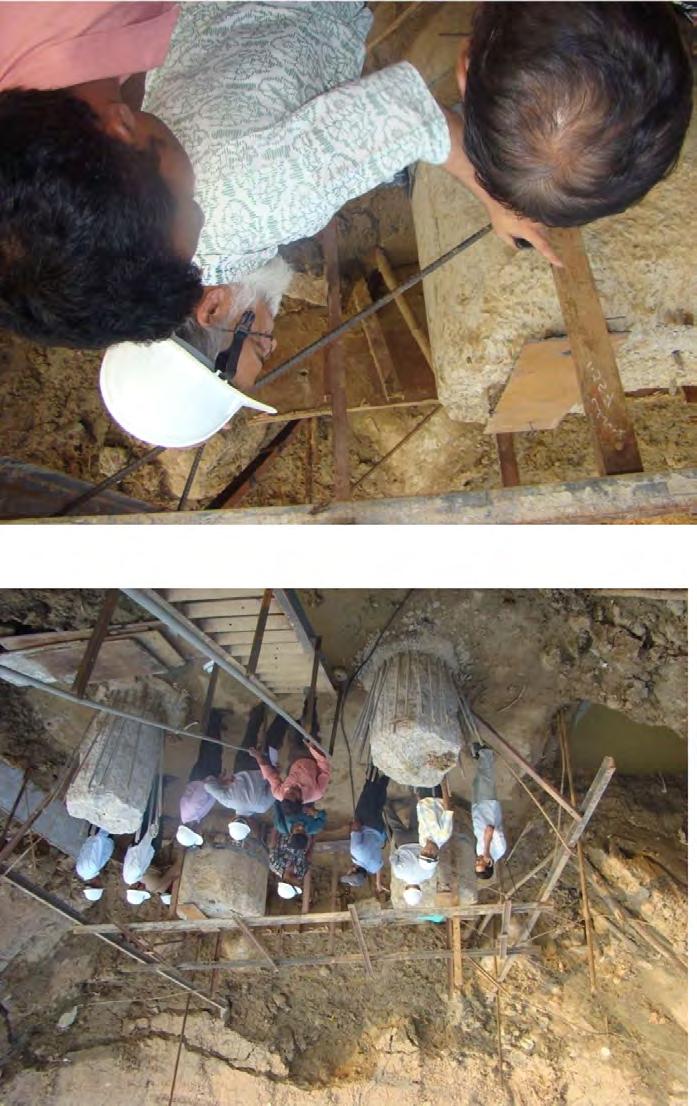
151

152