Aubert Ndjolba Structural Option PENN COLLEGE OF TECHNOLOGY. Pro-Con Structural Study of Alternate Floor Systems. Faculty advisor: Dr.
|
|
|
- Gilbert Lynch
- 5 years ago
- Views:
Transcription


1 TECHNICAL REPORT II Aubert Ndjolba Structural Option PENN COLLEGE OF TECHNOLOGY Pro-Con Structural Study of Alternate Floor Systems Faculty advisor: Dr. Boothby Date: 10/19/11
2 Table of Contents: Executive Summary.3 Building Introduction...4 Structural Overview.5 Foundation...5 Floor Systems..6 Framing System...7 Lateral System.8 Roof System Design Codes.10 Materials Used...11 Gravity Loads 13 Floor Systems Analysis.15 Existing: Composite Deck on Floor joists. 16 Proposed: Composite Deck on Wide Flange Beams Proposed: One-way Slab Proposed: Hollow Core Planks on Beam...19 Floor System Comparison.20 Conclusion.21 Appendices 22 Appendix A: Composite Deck on Floor Joists Appendix B: Composite Deck on Wide Flange Appendix C: One-way Slab...29 Appendix D: Hollow Core Planks Appendix E: Floor Plans 36 2
3 EXECUTIVE SUMMARY The purpose of the Technical Report II is to analyze the pros and cons of alternate floor systems of Dauphin Hall. An analysis of the existing composite deck together with three other floor systems was performed to provide different options that may be considered for the Dauphin Hall. The following floor systems were analyzed for a typical bay size of : Composite deck on floor joists Composite deck on wide flange beam One-way slab Hollow-core Plank with concrete topping By vulcraft Design Catalog and AISC Steel Construction Manual, a 3VL16 composite deck and a W18 40 beam form the composite system. The one-way slab was design using ACI and ACI Design Handbook. A 15 slab thickness with 10 O.C. and 7 O.C. reinforcement was found to yield for flexure, and shrinkage and temperature. Using the PCI Design handbook and the AISC Steel Construction Manual, a hollow core plank with 2 normal weight concrete and a W21 55 beam were picked for the hollow core floor system. Each system was analyzed based on the flowing criteria: cost of the assemblies, fire rating, structural or non-structural advantages or disadvantages, etc. All of the systems were found to be to some extend applicable; however, the composite deck on wide flange beams seems to be most cost effective and practical in this case. View table 8 for a complete system comparison. Partial drawings and hand calculations necessary for the understanding of the flooring systems are provided in the appendices of this report. 3


4 BUILDING INTRODUCTION The Pennsylvania College of Technology is located in the 200 block of Rose Street in Williamsport, PA. Dauphin Hall is the newest dormitory on campus constructed in August 2010 by Murray Associates Architects, P.C in collaboration with IMC as the general contractor; Woodburn & Associates, INC as the food service designer; Whitney, Bailey, Cox & Magnani, LLC as the civil engineering firm; and Gatter & Diehl, INC as the MEP firm. This new structure costs approximately $ 26,000,000 and used the design-bidbuild project delivery method. This latest addition of the student housing provides 268 students with suites and single rooms. A student seating commons enclosed with glass provides a social space for student collaboration. Located within the dormitory are other amenities such as: a 460 seat dining room, two private dining rooms for faculties, a 40 station satellite fitness center, two large leisure rooms, a student grocery store, laundry facilities, student mail boxes, Resident Life Offices, campus police office, and a Hall Coordinator apartment. Figure1: Map Figure 2: South facade To the right side are different facades provided for an understanding of the shape of the building. A set of floor plans are provided in appendix E as a supplementary documents for a better understanding. Figure 3: South facade 4
, which supports a 4 concrete slab reinforced with welded wire mesh on a composite deck.")
5 STRUCTURAL OVERVIEW Dauphin Hall rests entirely on a shallow foundation and stone piers. The exterior and interior walls are composed of masonry walls. The whole structure is made out of steel framing (joists, beams, and columns), which supports a 4 concrete slab reinforced with welded wire mesh on a composite deck. FOUNDATIONS Base on the analysis done by CMT Laboratories, Inc. for this site, the geotechnical engineers have determined that the site was filled with Brown Silty Clay, and Brown Silty Sand with Gravel. Furthermore, the cohesive alluvial soils beneath the fill materials have low shear strength. In light of these conditions, the conventional spread/column and continuous footing foundations will not provide adequate allowable bearing capacity to support the building. Deep foundations such as concrete filled tapered piles could support the structure but are not the most economical approach. Therefore, a practical solution is subsurface improvement with the use of shallow foundation. All in all, the final decision comes down to using stone piers which were considered the most technically sound and economically feasible method. Those stone piers are typically eighteen (18) to thirty-six (36) inches in diameter depending on their loading and settlement criteria. Figure 4: Typical Pier 5
. The joists supporting the floor system are spaced equally in column bays with a maximum spacing of 2-0 O.")
6 FLOOR SYSTEMS Due to the simplicity of the foot prints of the Dauphin hall, a typical floor consists of 4 concrete slab reinforced with 6 6 W2.9 W2.9 welded wire mesh. The concrete slab rests on 1 ½ - 20 gage composite deck (Vulcraft). The joists supporting the floor system are spaced equally in column bays with a maximum spacing of 2-0 O.C in areas of floor framing. A typical bay for the three floors above is The figure below provides a typical bay size. Figure 5: Typical Floor Bay Size (Red Square) 6

7 FRAMING SYSTEM Almost all the structural columns supporting the floors are either a wide flange W10 or W8. They are all encased by 5/8 Gypsum board or 6 painted CMU. In locations near the stair cases, HSS columns were used. Concrete Masonry Units (CMU) is the typical interior partitions. 7


8 LATERAL SYSTEM To resist the lateral system in the dauphin Hall, the structural engineers used wind moment frames with moment connections throughout the building. This configuration provides no obstruction and therefore allows a great use of the open floor plan. View the following details. 8

9 ROOF SYSTEMS There is only one roof system on the Dauphin Hall dormitory due to the similarity of the outline of the building. The whole roof is composed of 1 1/2 20 gage type B roof decks, which rests on light gage trusses at 2-0 O.C. The joists supporting the roof system are spaced at a maximum distance of 4-0 O.C. between the column bays. Figure 6: Roof plans 9
10 DESIGN CODES All equipments and components of the Dauphin Hall shall comply with all applicable latest editions of articles and sections of the following codes in compliances with all Federal, State, County, and Local ordinances and regulations: 2006 International Building Code (IBC) National Electrical Code (NEC), Uniform Plumbing Code (UPC), National Sanitation Foundation (NSF) Specifications for structural concrete for buildings (ACI 301) Building Code Requirements for Reinforced Concrete (ACI ) Recommended Practice for Hot Weather Concreting (ACI 305R) Recommended Practice for Cold Weather Concreting (ACI 306R) Recommended Practice for Concrete Formwork (ACI 347) American Society of Civil Engineers (ASCE 7-10) 10
11 MATERIALS USED The following table provides a list of materials used in the design of this building. Those values were found in the structural drawing and the specifications. Concrete Usage Weight Strength (psi) Footings Normal 4000 Foundation alls Normal 4000 Slab-on-Grade Normal 4000 Suspended Slabs Normal 4000 Toppings Normal 5000 Piers Normal 4000 Table 1: Concrete materials Steel Type Standard Grade W-Shaped Structural Steel ASTM A 572/A 572M 50 Channels, Angles-Shapes ASTM A 36/A 36M 36 Plate and Bar ASTM A 36/A 36M 36 Cold-Formed Hollow SS ASTM A 500 B Steel Pipe ASTM A 53/A 53M B Bolts, Nuts, and Washers ASTM A325/ASTM F 1852 N/A Steel Deck ASTM A 653 A Reinforcing Bars ASTM A 615/A 615M 60 Deformed Bars ASTM 767 A Welded Wire Fabric ASTM A Table 2: Steel materials 11
12 Masonry Type Standard Strength (psi) Concrete Block ASTM C 90/ ASTM C Split Face CMU ASTM C 90lightweight 1900 Bond Beam N/A 3000 Precast Stone N/A Concrete Brick ASTM C 1634/ASTM C 55 N/A Mortar ASTM C 979 N/A Grout ASTM C 404 N/A Table 3: Masonry materials Miscellaneous Type Strength (psi) Concrete Fill 3000 Non-Shrink Nonmetallic Grout ASTM C 1107 Table 4: Miscellaneous materials 12
13 GRAVITY LOADS Included in this report is a summary of dead, live, and snow loads used in the thesis design. There were compared to the actual design loads in the structural drawings. Several members were checked in the technical report I to verify adequacy. DEAD AND LIVE LOADS Superimposed Dead Loads Description Design Loads Thesis Loads Roof Roofing 3 PSF 3 PSF Framing 5 PSF 10 PSF Insulation 3 PSF 3 PSF Ceiling 2 PSF 2 PSF Elec./Lights 3 PSF 3 PSF Mechanical 5 PSF 5 PSF Sprinklers 3 PSF 3 PSF Miscellaneous 1 PSF 1 PSF Total 25 PSF 30 PSF Floor 4 Slab and Deck 44 PSF 57 PSF Framing 5 PSF 15 PSF Mechanical 5 PSF 5 PSF Elec./Lights 3 PSF 3 PSF Ceiling 2 PSF 2 PSF Sprinklers 3 PSF 3 PSF Miscellaneous 3 PSF 3 PSF Total 65 PSF 88 PSF Superimposed DL 30 PSF Snow 35 PSF 30 PSF Table 5: Design Dead Loads 13
14 Description Quantity (ft2) Ground floor 14,473 2 nd Floor 10,320 3 rd Floor 10,320 4 th Floor 10,320 Roof 10,320 Table 6: Area of Typical Floor Design Live Loads Description Design Loads Thesis Loads Roof 35 PSF 30 PSF First Floor 100 PSF 100 PSF Stairs 100 PSF 100 PSF Dorm Rooms 40 PSF 40 PSF Corridors 100 PSF 100 PSF Storage 125 PSF 125 PSF Mechanical room 150 PSF 125 PSF Common Areas 100 PSF 100 PSF Table 7: Design Live Load 14
15 FLOOR SYSTEM ANALYSIS A spot checked of the existing 4 normal weight concrete slab on 1-1/2-20 gage composite steel deck was done on a typical bay and all its calculations can be found in appendix A. This system was then compared to a one-way slab, a composite deck on a beam, and a hollow-core slab of the same bay. These preliminary sizes were estimated using ACI , IBC 2009, PCI design handbook, and other design aids. Based on the RS Means: Square Foot Costs 2011, a cost analysis was done on the four floor systems to determine which one is cost effective. A complete hand calculation of each system can be found in the appendixes. 15
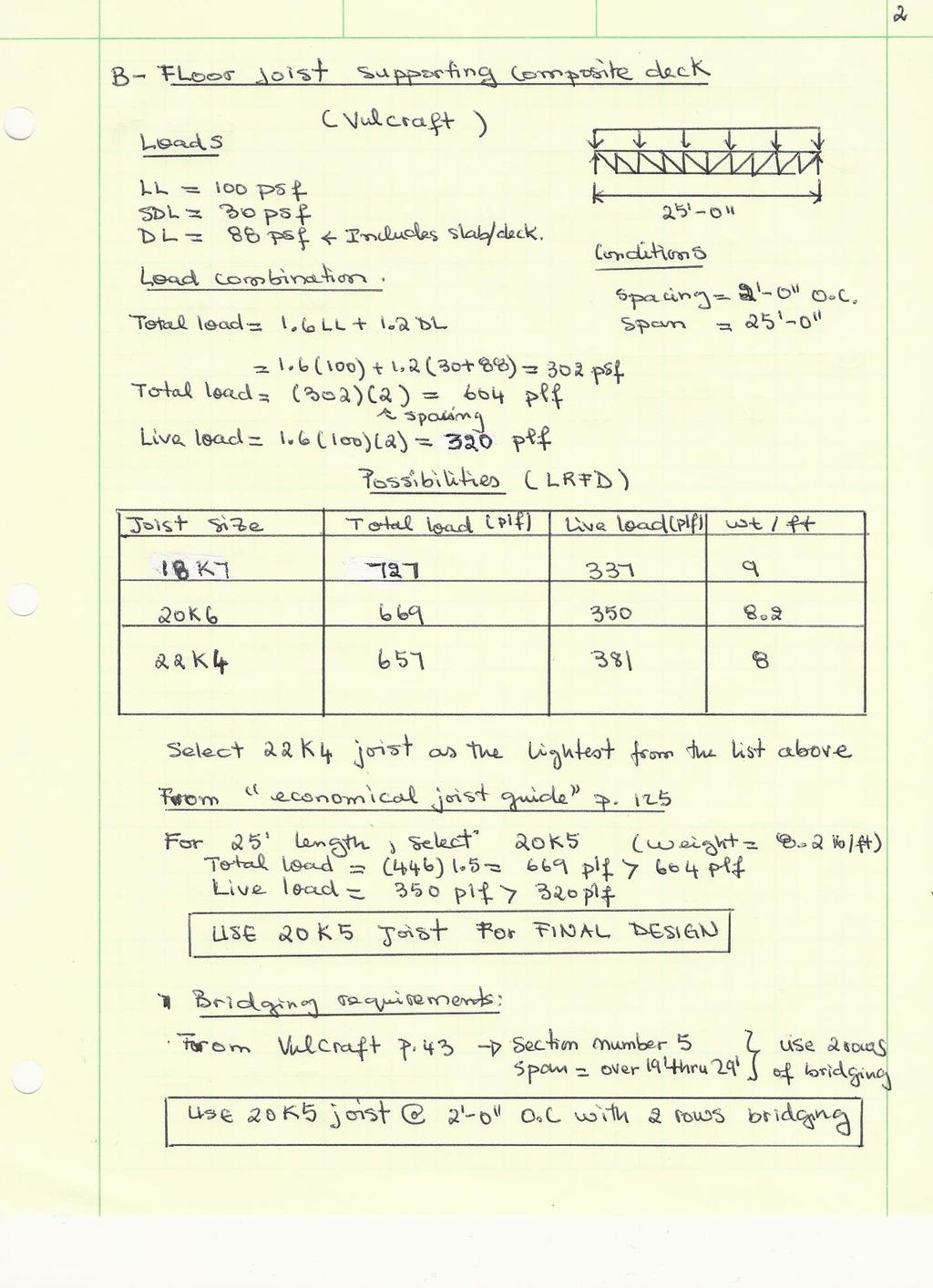
16 EXISTING FLOOR SYSTEM: SLAB & COMPOSITE DECK ON FLOOR JOISTS Decking Using Vulcraft Manual, a 1.5VL 20 composite deck with 4 normal weight concrete was found to be more than adequate for unshored length and has more than the required strength for loading. The deck has a 1 ½ hour fire rating. Overall the composite deck was overdesigned. Floor Joists supporting Composite Deck For a factored total load and live load of 604 plf and 320 plf respectively, we find in the Vulcraft manual that a 18K7, 20K6, and 22K4 are all satisfactory joists for a 25 span. Based on their weight, a 22K4 seems to be the lightest of the group. However, from the economical joist guide section on page 125 of the same manual, we find that a 20K5 is more economical. Therefore, we pick a 20K5 joist spaced at 2-0 O.C. with 2 rows of bridging for our final design. However, the existing design joists are overdesigned using 22K6 joists spaced at 2-0 O.C. This member has 25% more strength than required. Advantages: One of the major advantages of using this floor system is that it provides a great space underneath the floor for mechanical and electrical equipment. All the lighting fixtures can be hanged straight on the joists. The composite deck provides a profile shape that uses less concrete than the conventional system; therefore reducing the size and cost of elements used in the primary structure and foundations. It also provides a great advantage in seismic, gravity and foundation design by reducing the weight of the structure. Moreover, temporary props can be eliminated resulting in faster erection and a shortening of the construction program. Additionally, it provides a working platform and is cost and energy efficient, and recyclable. Disadvantages: With this system being used throughout the building, the cost of steel on this project will increase. Moreover, steel joist floors do not provide an aesthetic ceiling for the floors below. In addition, composite decks have sagging problems due to the weight of the deck, and are temperature sensitive. Composite decks tend to expand in hot weather and contract in cold weather making many decks less suitable for bearing a lot of weight. Finally, if the deck is damaged, it must be completely replaced. 16
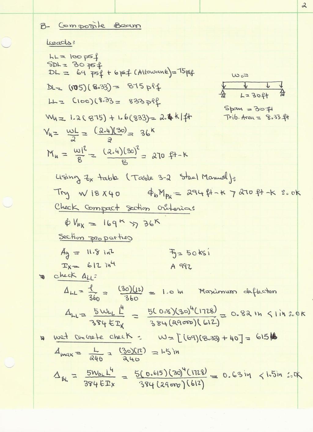
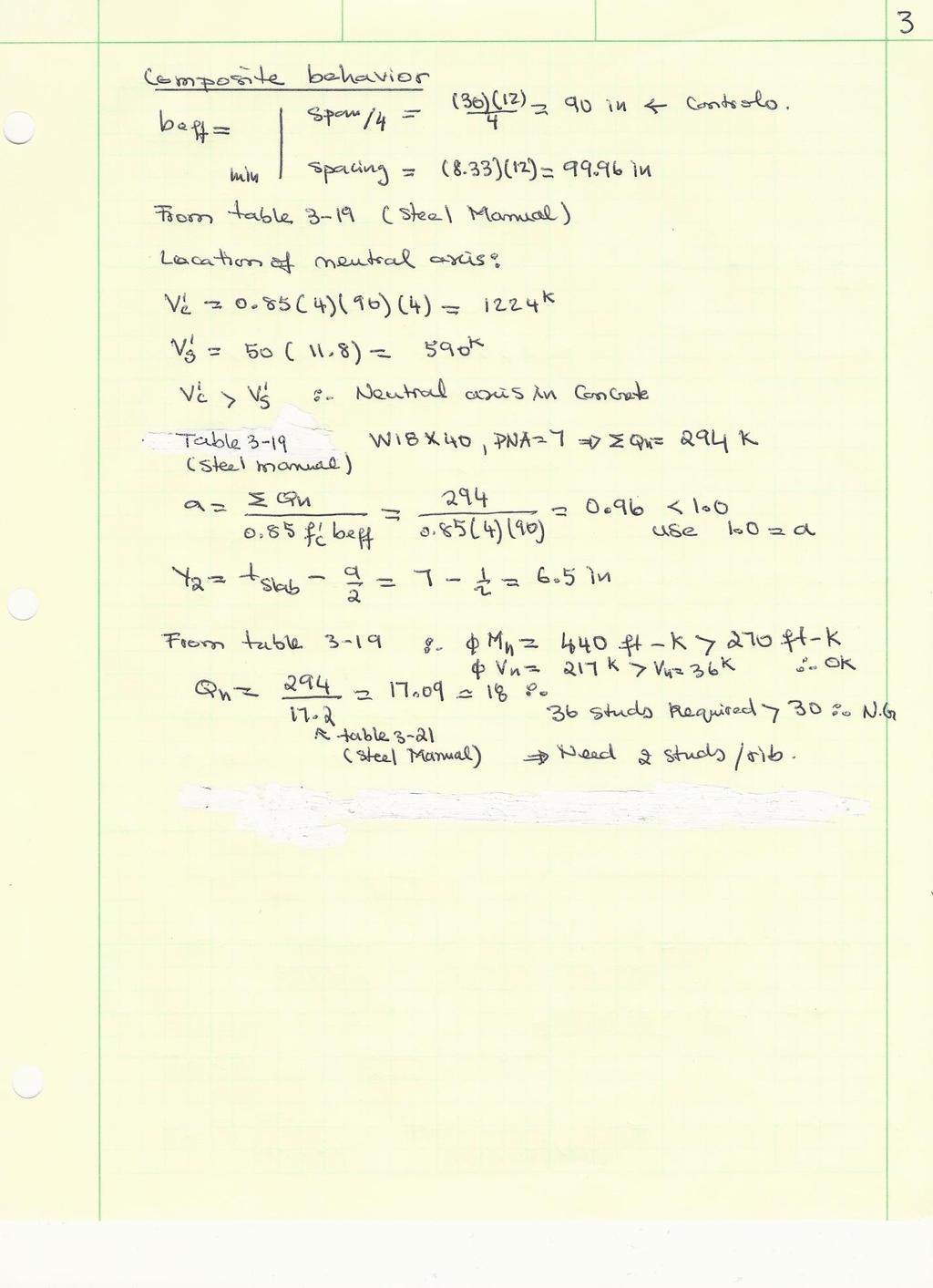
17 PROOSED FLOOR SYSTEM: COMPOSITE DECK ON WIDE FLANGE BEAMS This system is a derivation of the above floor system in order to reduce the overall cost of structural steel in the project. A 3-16 gage composite deck with 4 normal weight concrete with two wide flange beams spanning in the longer direction seems more suitable. The deck is perpendicular to the beams. Decking: For a 3 span condition with a total factored load of 196psf, a 3VL16 deck has 11-4 construction span, which is more than the 8-4 required span for unshored condition. The given strength turns out to be slightly over 25% more than the required strength when added the slab weight. The unprotected deck achieves a 1 ½ hour fire rating for a 4 normal weight concrete (Vulcraft Manual). Composite Beam: A W18 40 was proven to have enough flexural strength (ΦM= 294 ft-k >270 ft-k) to support the given loads. The compact section criterion is also satisfied along with live load deflection and wet concrete deflection. The live load deflection was = 0.82 in < 1 in, and the wet concrete deflection was = 0.63 in < 1.5 in. In addition, two studs per rib are required to achieve the desired strength. Advantages: Similarly to the previous system, this system will allow a depth of 18 inches in the ceiling for lighting fixtures and mechanical equipment for the floors below. Also, this will reduce the cost of structural steel in the project considerably. Another beneficial advantage of using this type of deck is that by applying some type of fire protection on the deck, we can achieve a higher fire rating resistance. Disadvantages: Compared to the previous system, the 18 inches ceiling height would be a challenge for the mechanical and electrical equipment. Flexible duck or other types of ventilation may be required if this system is chosen. Moreover, additional fire proofing material may be required on the beam, which could slightly increase the cost. 17
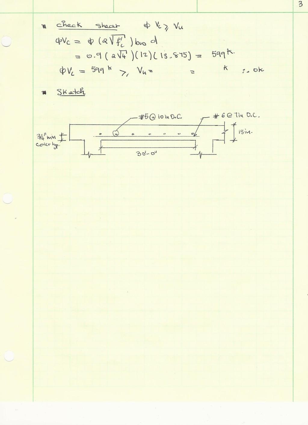
18 PROPOSED FLOOR SYSTEM: ONE-WAY SLAB A thickness of 15 inches was determined to work on a 30 ft span with a live load of 100 psf and a superimposed dead load of 30 psf using PCI Design Handbook and ACI For these load conditions, we can provide # 6 bars at 7 inches O.C. in the short direction to meet flexural requirements of 31 ft-k > 27 ft-k. To limit the effect of temperature and shrinkage, a reinforcement of the slab with # 5 10 inches O.C. is required (Note: 14 O.C. could be used for consistency). A spacing of 7 inches is more than enough to withstand cracking and shear. By visual inspection shear is not a controlling factor here. Advantages: This floor system configuration provides a greater floor to floor height. Therefore, another floor can be added to the existing system height without increasing the height too much. Another advantage of this system is that during construction, the form work can be reused multiple times. In addition, there is no need for fire protection due to the 15 inches thickness of the slab. Disadvantages: The ceiling will not provide a space for mechanical or electrical equipment. Vibration may be a problem in this case. In addition, the foundation of the building will need to be rechecked due to the weight of the slab. 18


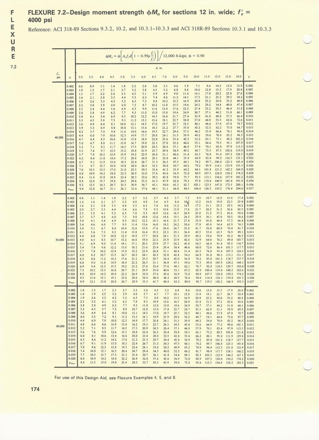
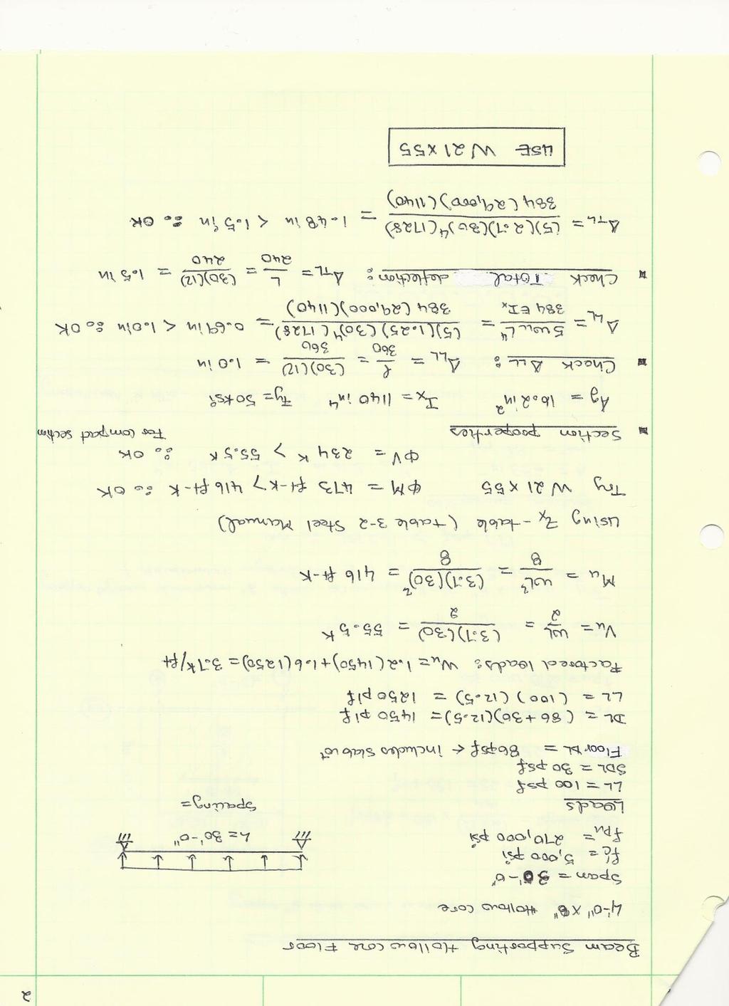
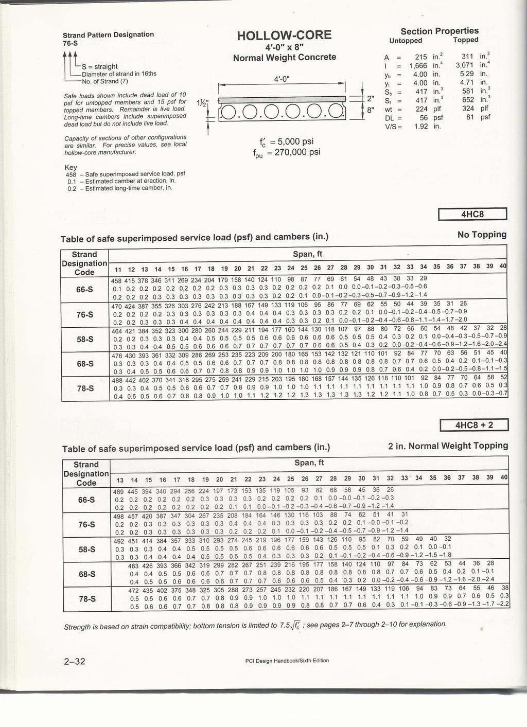
19 PROPOSED FLOOR SYSTEM: HOLLOW-CORE ON BEAM Precast hollow-core planks were proposed for the same bay. Using the PCI Design Handbook, a with 2 normal weight concrete was found to be sufficient to support the load across the 25 span. A W was used to support the hollow core planks in the 30 direction. This beam was checked for deflection and all supporting calculations can be found in Appendix D. Advantages: The hollow core planks being precast meaning the system was constructed under controlled conditions providing a maximum strength capacity to be attained. Since the system is being produced in a factory, the general contractor can save time in the erection process and storage space. Disadvantages: The steel beam supporting the hollow core planks will need fire protection for the whole system to achieve a 2 hours fire rating. 19
20 SYSTEM COMPARISON Floor System Comparison Existing Composite Deck on Floor joists Composite Deck on Wide Flange Beam Floor systems One-way Slab Hollow Core Plank System Weight (psf) limitations Cost and safety Slab depth (in) Total depth (in) Fire rating 1 ½ 1 ½ 2 2 Extra fire proofing Required Total Cost($/SF) No Yes No Yes cost of joists Foundation impact N/A Yes Yes Yes Architectural impact N/A Yes Yes Yes Impact Consideration Constructability Easy Easy Moderate Easy Vibration concerns Some Some Minimal Minimal Possible alternative N/A Yes Yes Yes Additional study N/A Yes Yes Yes Table 8: System Comparison 20
21 CONCLUSION Three alternative systems were studied in addition to the existing system. These systems are: a composite deck on a wide flange beam, a one way slab, and a hollow core plank on steel beams. All the analyses were done on a typical bay of 25 feet by 30 feet. The composite deck and beam were designed using the Vulcraft Design Catalog and the AISC Steel Construction manual. The composite system consists of a 4 normal weight concrete with a 3VL16 composite deck and a W18 40 beam. The one-way slab system is composed of a 15 normal weight slab reinforced with 10 O.C. in the 30 feet direction and 7 O.C. in the 25 feet direction for flexure, shrinkage and temperature respectively. The one-way slab was designed using ACI and ACI Design Handbook (Volume 1). Based on the loading conditions, the PCI Design Handbook (6 th Edition) recommends a hollow core plank. A W21 55 beam will support the hollow core planks. After reviewing the advantages and disadvantages of each system, two systems were determined to not be viable alternative: The hollow core planks and the one-way slab. Both systems increase the weight of the building considerably. The hollow core planks are more expensive and have the greatest total depth of all the systems. Therefore, the best alternative system may be the composite deck on a wide flange beam. However, this system will have a slightly higher cost due to additional fire proofing required. A further study of the composite deck on wide flange beam system will need to be done. 21
22 APPENDICES 22

23 APPENDIX A: EXISTING SYSTEM: COMPOSITE DECK ON FLOOR JOISTS 23
24 24

25 25

26 APPENDIX B: COMPOSITE DECK ON WIDE FLANGE BEAM 26
27 27
28 28

29 APPENDIX C: PROPOSED FLOOR SYSTEM: ONE-WAY SLAB 29

30 Could use for consistency (As = 0.38 in 2 /ft) 30
31 6.3 k 31
32 32

33 APPENDIX D: HOLLOW CORE PLANKS ON BEAM 33
34 34
35 35

36 APPENDIX E: FLOOR PLANS Figure 17: Ground floor 36

37 Figure 18: Upper Floors 37