Tahmoor Coking Coal Operations - Longwall 32
|
|
|
- Dominic Knight
- 5 years ago
- Views:
Transcription


1 REPORT: ENDEAVOUR ENERGY SUBSIDENCE MANAGEMENT PLAN SIMEC Mining: Tahmoor Coking Coal Operations - Longwall 32 Management Plan for Potential Impacts to Endeavour Energy Infrastructure MSEC AUGUST 2018 REPORT NUMBER: MSEC REVISION A
2 AUTHORISATION OF MANAGEMENT PLAN Authorised on behalf of Tahmoor Coking Coal Operations: Name: Signature: Position: Date: Authorised on behalf of Endeavour Energy: Name: Signature: Position: Date: PAGE i
3 DOCUMENT REGISTER Date Report No. Rev Comments Mar-06 MSEC A Draft for Submission to Endeavour Energy (formerly Integral Energy) May-06 MSEC B Agreed plan Aug-06 MSEC C Chapter 1 amended Sep-08 MSEC D Updated for Longwall 25 May-10 MSEC A Updated for Longwall 26 Sep-12 MSEC A Updated for Longwalls 27 to 30 Oct-12 MSEC B Updated after consultation with Endeavour Energy Jun-17 MSEC A Updated for Longwall 31 Aug-18 MSEC A Updated for Longwall 32 References:- AS/NZS 4360:1999 Risk Management AS/NZS ISO 31000:2009 Risk Management Principles and guidelines Glencore (2014) Glencore Coal Assets Australia Risk Management Matrix, Glencore, September Glencore (2018) Environmental Risk Assessment: Tahmoor Underground Longwall 32 Surface and Subsurface Infrastructure Electrical Infrastructure, Tahmoor Coking Coal Operations, May MSO (2017) Managing risks of subsidence Guide WHS (Mines and Petroleum Sites) Legislation, NSW Department of Planning & Environment, Resources Regulator, Mine Safety Operations, February MSEC (2014) Tahmoor Colliery Longwalls 31 to 37 - Subsidence Predictions and Impact Assessments for Natural and Built Features in support of the SMP Application. (Report MSEC647, Revision A, December 2014), prepared by Mine Subsidence Engineering Consultants. SCT (2018a) Structure determinations of the Nepean Fault adjacent to Tahmoor Mine, SCT Operations, Report No. TAH4817, May SCT (2018b) Investigation into the Potential Impact of the Nepean Fault on Longwall 32 Subsidence, SCT Operations, Report No. TAH4821, May Endeavour Energy (2018) Endeavour Energy Network: Result of On Site Audit Endeavour Energy Assets for SIMEC Mining - Tahmoor Colliery Longwall 32, Endeavour Energy, July PAGE ii
4 CONTENTS 1.0 INTRODUCTION Background Endeavour Energy s electrical assets potentially affected by Longwall Consultation Consultation with Endeavour Energy Consultation with Government Agencies & Key Infrastructure Stakeholders Limitations Objectives Scope Proposed Mining Schedule Definition of Active Subsidence Zone Compensation METHOD OF ASSESSMENT OF POTENTIAL MINE SUBSIDENCE IMPACTS NSW Work Health & Safety Legislation General Consequence Likelihood Hazard Method of assessment of potential mine subsidence impacts SUBSIDENCE PREDICTIONS AND ASSESSMENT OF POTENTIAL MINE SUBSIDENCE IMPACTS Maximum Predicted Conventional Subsidence Parameters Observed subsidence during the mining of Longwalls 22 to Predicted Strain Analysis of strains measured in survey bays Analysis of strains measured along whole monitoring lines Geological structures Identification of geological structures Experience of subsidence movements between previously extracted longwalls and Nepean Fault at Tahmoor Coking Coal Operations Potential effects of the Nepean Fault and associated geological structures on the development of subsidence during the extraction of Longwall Potential effects of geological structures on the development of subsidence during the extraction of Longwall Managing Public Safety Subsidence Impact Management Process for Infrastructure Summary of Potential Impacts Identification of subsidence hazards that could give rise to risks to health and safety Powerlines Predicted subsidence movements Potential subsidence impacts on powerlines Power poles MANAGEMENT OF POTENTIAL IMPACTS Infrastructure Management Group (IMG) 28 PAGE iii
5 4.2. Development and Selection of Risk Control Measures Selection of Risk Controls for Electrical Infrastructure Monitoring Measures Ground Surveys along streets Visual Inspections Changes to Monitoring Frequencies Triggers and Responses Subsidence Impact Management Procedures REPORTING AND COMMUNICATION PLAN Consultation, Co-operation and Co-ordination IMG Meetings AUDIT AND REVIEW RECORD KEEPING CONTACT LIST 34 APPENDIX A. Drawings and Supporting Documentation 35 PAGE iv
6 LIST OF TABLES AND FIGURES Tables Tables are prefaced by the number of the chapter in which they are presented. Table No. Description Page Table 1.1 Longwall dimensions... 1 Table 1.2 Schedule of Mining... 3 Table 3.1 Maximum Predicted Conventional Subsidence Parameters due to the Extraction of Longwall Table 3.2 Summary of Potential Mine Subsidence Impacts Table 3.3 Maximum predicted total conventional subsidence, tilt and curvature for the powerlines Table 3.4 Summary of poles recommended for monitoring during Longwall Table 4.1 Risk Control Procedures during the extraction of Tahmoor Coking Coal Operations Longwall Figures Figures are prefaced by the number of the chapter or the letter of the appendix in which they are presented. Figure No. Description Page Fig. 1.1 Diagrammatic Representation of Active Subsidence Zone... 4 Fig. 3.1 Fig. 3.2 Fig. 3.3 Fig. 3.4 Observed development of subsidence of survey pegs above the centrelines of Longwalls 24A to Distributions of the measured maximum tensile and compressive strains for surveys bays located above goaf... 9 Distributions of the measured maximum tensile and compressive strains for survey bays located above solid coal Distributions of measured maximum tensile and compressive strains anywhere along the monitoring lines Fig. 3.5 Cross-section of Nepean Fault near Longwall 32 by SCT (2018a) Fig. 3.6 Fig. 3.7 Fig. 3.8 Cross-section showing the mapped geological structures by SCT (2018a), and predicted subsidence profiles Locations of ground survey lines in relation to the mapped geological structures by SCT (2018a) Distributions of the Measured Maximum Tensile and Compressive Strains for Bays Located over Solid Coal between previously extracted longwalls at Tahmoor Coking Coal Operations and the Nepean Fault Fig. 3.9 Observed ground strains at selected sites during the mining of Longwalls 25 to Fig Fig Fig Observed total subsidence profiles along the Stilton Northern Dam Line during the mining of Longwalls 29 to Observed total subsidence profiles along the Remembrance Drive East Line during the mining of Longwalls Changes in vertical alignment across a geological fault within a railway cutting during the mining of Longwalls 29 to 31 at Tahmoor Coking Coal Operations Fig Flowchart for Subsidence Impact Management Process Fig Fig Fig kV Powerline (left) and 11kV Powerline (right) within Sydney Water s Picton Water Recycling Plant Predicted profiles of total subsidence, tilt and curvature for the powerline along Remembrance Drive due to the mining of Longwalls 22 to Predicted profiles of total subsidence, tilt and curvature for the powerline along Bridge Street due to the mining of Longwalls 22 to PAGE v
7 Drawings Drawings referred to in this report are included in Appendix A at the end of this report. Drawing No. Description Revision MSEC Monitoring over Longwall 32 C MSEC Electrical Infrastructure A MSEC Critical Power Poles A PAGE vi
8 1.0 INTRODUCTION 1.1. Background Tahmoor Coking Coal Operations is located approximately 80 km south-west of Sydney in the township of Tahmoor NSW. It is managed and operated by SIMEC Mining. Tahmoor Coking Coal Operations has previously mined 30 longwalls to the north and west of the mine s current location. It is currently mining Longwall 31. Longwall 32 is a continuation of a series of longwalls that extend into the Tahmoor North Lease area, which began with Longwall 22. The longwall panels are located between the Bargo River in the south-east, the township of Thirlmere in the west and Picton in the north. Longwall 32 is located beneath the rural area between Tahmoor, Thirlmere and Picton, including part of the South Picton industrial area. Electrical infrastructure owned by Endeavour Energy is located within this area. A summary of the dimensions of Longwall 32 is provided in Table 1.1. Table 1.1 Longwall dimensions Longwall Overall void length including the installation heading (m) Overall void width including the first workings (m) Overall tailgate chain pillar width (m) Longwall This Management Plan provides detailed information about how the risks associated with mining beneath the infrastructure will be managed by Tahmoor Coking Coal Operations and Endeavour Energy. The Management Plan is a live document that can be amended at any stage of mining, to meet the changing needs of Tahmoor Coking Coal Operations and Endeavour Energy Endeavour Energy s electrical assets potentially affected by Longwall 32 A map showing the locations of Endeavour Energy s electrical infrastructure in relation to Longwall 32 is shown in Drawing No. MSEC As shown in Drawing No. MSEC , the majority of the powerlines are low voltage. A 66kV powerline follows the alignment of Remembrance Drive before it heads west through property owned by Sydney Water s Picton Water Recycling Plant. A number of 11kV powerlines are potentially affected by the extraction of Longwall 32, including powerlines on Bridge Street, Henry Street, Remembrance Drive and Thirlmere Way Consultation Consultation with Endeavour Energy Tahmoor Coking Coal Operations regularly consults with Endeavour Energy in relation to mine subsidence effects from mining. This includes consultation during the development of Subsidence Management Plans for previous Longwalls 22 to 31, and regular reporting of subsidence movements and impacts. Details regarding consultation and engagement are outlined below: A risk assessment was held on 10 May 2018, which was attended by representatives from Endeavour Energy and Tahmoor Coking Coal Operations. to David Olley (Endeavour Energy) on 9 May 2018 requesting Endeavour Energy assessment of critical poles for Longwall 32 Management Plan. from Ben Logue (Endeavour Energy) on 24 July 2018 to Belinda Clayton (Tahmoor Coking Coal Operations) with the Critical Pole Audit Report for Longwall 32. Meeting with Endeavour Energy, Ron Bush (Tahmoor Coking Coal Operations), Belinda Clayton (Tahmoor Coking Coal Operations), Matthew Montgomery (Subsidence Advisory NSW) in August 2018 to discuss the draft Subsidence Management Plan for Longwall 32. Tahmoor Coking Coal Operations will continue to consult regularly with Endeavour Energy during the extraction of Longwall 32 in relation to mine subsidence effects from mining. PAGE 1
9 Consultation with Government Agencies & Key Infrastructure Stakeholders Government agencies including the NSW Department of Planning & Environment, Resources Regulator, Mine Safety Operations, Subsidence Advisory NSW and key infrastructure stakeholders including Wollondilly Shire Council, Sydney Water, Telstra and Jemena have also been consulted as part of the Subsidence Management Plan (SMP) approval process Limitations This Management Plan is based on the predictions of the effects of mining on surface infrastructure as provided in Report No. MSEC647 by Mine Subsidence Engineering Consultants (MSEC, 2014). Predictions are based on the planned configuration of Longwall 32 at Tahmoor Coking Coal Operations (as shown in Drawing No. MSEC ), along with available geological information and data from numerous subsidence studies for longwalls previously mined in the area. Infrastructure considered in this Plan has been identified from site visits and aerial photographs and from discussions between Tahmoor Coking Coal Operations and Endeavour Energy representatives. The impacts of mining on surface and sub-surface features have been assessed in detail. However, it is recognised that the prediction and assessment of subsidence can be relied upon only to a certain extent. The limitations of the prediction and assessment of mine subsidence are discussed in report MSEC647 by Mine Subsidence Engineering Consultants. As discussed in the report, there is a low probability that ground movements and their impacts could exceed the predictions and assessments. However, if these potentially higher impacts are considered prior to mining, they can be managed. This Management Plan will not necessarily prevent impacts from longwall mining, but will limit the impacts by establishing appropriate procedures that can be followed should evidence of increased impacts emerge Objectives The objectives of this Management Plan are to establish procedures to measure, control, mitigate and repair potential impacts that might occur to electrical infrastructure. The objectives of the Management Plan have been developed to:- Ensure the safe and serviceable operation of all surface infrastructure. Public and workplace safety is paramount. Ensure that the health and safety of people who may be present on public property or Endeavour Energy property are not put at risk due to mine subsidence. Disruption and inconvenience should be avoided or, if unavoidable, kept to minimal levels. Monitor ground movements and the condition of infrastructure during mining. Initiate action to mitigate or remedy potential significant impacts that are expected to occur on the surface. Provide a plan of action in the event that the impacts of mine subsidence are greater than those that are predicted. Establish a clearly defined decision-making process to ensure timely implementation of risk control measures for high consequence but low likelihood mine subsidence induced hazards that involve potential serious injury or illness to a person or persons that may require emergency evacuation, entry or access restriction or suspension of work activities. Provide a forum to report, discuss and record impacts to the surface. This will involve Tahmoor Coking Coal Operations, Endeavour Energy, relevant government agencies as required, and consultants as required. Establish lines of communication and emergency contacts Scope The Management Plan is to be used to protect and monitor the condition of the Endeavour Energy infrastructure identified to be at risk due to mine subsidence and to ensure that the health and safety of people who may be resent on public property or Endeavour Energy property are not put at risk due to mine subsidence. The major items at risk are:- Powerlines Power poles The powerlines and power poles are shown in Drawing No. MSEC and the critical power poles are shown in Drawing No. MSEC PAGE 2
10 The Management Plan only covers the electrical infrastructure that is located within the limit of subsidence, which defines the extent of land that may be affected by mine subsidence as a result of mining Longwall 32 only. The management plan does not include other electrical infrastructure owned by Endeavour Energy which lies outside the extent of this area. This Management Plan does not include Endeavour Energy Picton Field Service Centre on Bridge Street. A separate management plan was developed in consultation with Endeavour Energy in relation to this property prior to the influence of Longwalls 30 and 31, and an updated management plan will be prepared for Longwall Proposed Mining Schedule It is planned that Longwall 32 will extract coal working northwest from the south-eastern end. This Management Plan covers longwall mining until completion of mining in Longwall 32 and for sufficient time thereafter to allow for completion of subsidence effects. The current schedule of mining is shown in Table 1.2. Table 1.2 Schedule of Mining Longwall Start Date Completion Date Longwall 32 September 2018 September 2019 Please note the above Schedule is subject to change due to unforeseen impacts on mining progress. Tahmoor Coking Coal Operations will keep Endeavour Energy informed of changes Definition of Active Subsidence Zone As a longwall progresses, subsidence begins to develop at a point in front of the longwall face and continues to develop after the longwall passes. The majority of subsidence movement typically occurs within an area 150 metres in front of the longwall face to an area 450 metres behind the longwall face. This is termed the active subsidence zone for the purposes of this Management Plan, where surface monitoring is generally conducted. The active subsidence zone for each longwall is defined by the area bounded by the predicted 20 mm subsidence contour for the active longwall and a distance of 150 metres in front and 450 metres behind the active longwall face, as shown by Fig PAGE 3
 is administered by")


11 Fig. 1.1 Diagrammatic Representation of Active Subsidence Zone 1.9. Compensation The Coal Mine Subsidence Compensation Act 2017 (MSC Act) is administered by Subsidence Advisory NSW (Mine Subsidence Board). Currently, under the Coal Mine Subsidence Compensation Act 2017, any claim for mine subsidence damage needs to be lodged with Subsidence Advisory NSW. Subsidence Advisory NSW staff will arrange for the damage to be assessed by an independent specialist assessor. If the damage is attributable to mine subsidence, a scope will be prepared and compensation will be determined. For further details please refer to Guidelines Process for Claiming Mine Subsidence Compensation at PAGE 4
12 2.0 METHOD OF ASSESSMENT OF POTENTIAL MINE SUBSIDENCE IMPACTS 2.1. NSW Work Health & Safety Legislation All persons conducting a business or undertaking (PCBUs), including mine operators and contractors, have a primary duty of care to ensure the health and safety of workers they engage, or whose work activities they influence or direct. The responsibilities are legislated in Work Health and Safety Act 2011 and the Work Health and Safety (Mines and Petroleum Sites) Act 2013 and associated Regulations (collectively referred to as the WHS laws ). The Work Health and Safety (Mines and Petroleum Sites) Regulation 2014 commenced on 1 February 2015 and contains specific regulations in relation to mine subsidence. As outlined in the Guide by the NSW Department of Trade & Investment Mine Safety: a PCBU must manage risks to health and safety associated with mining operations at the mine by: complying with any specific requirements under the WHS laws identifying reasonably foreseeable hazards that could give rise to health and safety risks ensuring that a competent person assesses the risk eliminating risks to health and safety so far as is reasonably practicable minimising risks so far as is reasonably practicable by applying the hierarchy of control measures, any risks that it is are not reasonably practical to eliminate maintaining control measures reviewing control measures. The mine operator s responsibilities include developing and implementing a safety management system that is used as the primary means of ensuring, so far as is reasonably practicable: the health and safety of workers at the mine, and that the health and safety of other people is not put at risk from the mine or work carried out as part of mining operations. Detailed guidelines have also been released by the NSW Department of Planning & Environment, Resources Regulator, Mine Safety Operations (MSO, 2017). The risk management process has been carried out in accordance with guidelines published by the NSW Department of Planning & Environment, Resources Regulator, Mine Safety Operations (MSO, 2017). The following main steps of subsidence risk management have been and will be undertaken, in accordance with the guidelines. 1. identification and understanding of subsidence hazards 2. assessment of risks of subsidence 3. development and selection of risk control measures 4. implementation and maintenance of risk control measures, and 5. continual improvement and change management. Each of the above steps have been or will be conducted together with the following processes. 1. consultation, co-operation and co-ordination, and 2. monitoring and review. This Management Plan documents the risk control measures that are planned to manage risks to health and safety associated with the mining of Longwall 32 in accordance with the WHS laws. PAGE 5
13 2.2. General The method of assessing potential mine subsidence impacts in the Management Plan is consistent with the Australian/New Zealand Standard for Risk Management. The Standard defines the terms used in the risk management process, which includes the identification, analysis, assessment, treatment and monitoring of potential mine subsidence impacts. In this context: Consequence The outcome of an event expressed qualitatively or quantitatively, being a loss, injury, disadvantage or gain. There may be a range of possible outcomes associated with an event. 1 The consequences of a hazard are rated from very slight to very severe Likelihood Used as a qualitative description of probability or frequency. 2 The likelihood can range from very rare to almost certain Hazard A source of potential harm or a situation with a potential to cause loss Method of assessment of potential mine subsidence impacts The method of assessing potential mine subsidence impacts combines the likelihood of an impact occurring with the consequence of the impact occurring. In this Management Plan, the likelihood and consequence are combined via the Glencore Coal Assets Australia Risk Matrix to determine an estimated level of risk for particular events or situations. A copy of the Risk Matrix is included in the Appendix of this Management Plan. The identified risks were also assessed using Endeavour Energy s Risk Criteria, which is attached to the Appendix. 1 AS/NZS 4360:1999 Risk Management pp2 2 AS/NZS 4360:1999 Risk Management pp2 3 AS/NZS 4360:1999 Risk Management pp2 PAGE 6
14 3.0 SUBSIDENCE PREDICTIONS AND ASSESSMENT OF POTENTIAL MINE SUBSIDENCE IMPACTS 3.1. Maximum Predicted Conventional Subsidence Parameters Predicted mining-induced conventional subsidence movements were provided in Report No. MSEC647, which was prepared in support of Tahmoor Coking Coal Operations SMP Application for Longwalls 31 to 37, and includes predictions due to the extraction of Longwall 32. A summary of the maximum predicted incremental subsidence parameters due to the extraction of Longwall 32 only and the maximum predicted total conventional subsidence parameters due to the extraction of Longwalls 22 to 32, are provided in Table 3.1. Table 3.1 Maximum Predicted Conventional Subsidence Parameters due to the Extraction of Longwall 32 Longwall Maximum Predicted Subsidence (mm) Maximum Predicted Tilt (mm/m) Maximum Predicted Hogging Curvature (1/km) Maximum Predicted Sagging Curvature (1/km) Increment due to LW32 only Total after extraction of LWs 22 to 32 1, The values provided in the above table are the maximum predicted conventional subsidence parameters which occur within the general longwall mining area, including the predicted movements resulting from the extraction of Longwalls 22 to 32. The location of the maximum predicted total subsidence is not directly above Longwall 32. Predicted maximum total subsidence directly above Longwall 32 is approximately 800 mm Observed subsidence during the mining of Longwalls 22 to 31 The extraction of longwalls at Tahmoor Coking Coal Operations has generally resulted in mine subsidence movements that were typical of those observed above other collieries in the Southern Coalfield of NSW at comparable depths of cover. However, observed subsidence was greater than the predicted values over Longwalls 24A and the southern parts of Longwalls 25 to 27. Monitoring during the mining of Longwalls 28 to 31 has found that subsidence behaviour has returned to normal levels. Survey Peg ST14 on Stilton Lane is located above the centreline of Longwall 31. As shown in Fig. 3.1, subsidence developed at an equivalent magnitude to pegs located above previously extracted Longwalls 28 to Incremental Subsidence (mm) Fig. 3.1 Observed development of subsidence of survey pegs above the centrelines of Longwalls 24A to 31 PAGE 7
15 Ground surveys will continue to be undertaken above Longwall 32. The survey results will be checked against predictions to confirm whether subsidence continues to develop in a normal manner during the mining of Longwall Predicted Strain The prediction of strain is more difficult than the predictions of subsidence, tilt and curvature. The reason for this is that strain is affected by many factors, including curvature and horizontal movement, as well as local variations in the near surface geology, the locations of pre-existing natural joints at bedrock, and the depth of bedrock. Survey tolerance can also represent a substantial portion of the measured strain, where the strains are of a low order of magnitude. The profiles of observed strain, therefore, can be irregular even when the profiles of observed subsidence, tilt and curvature are relatively smooth. In previous MSEC subsidence reports, predictions of conventional strain were provided based on the best estimate of the average relationship between curvature and strain. Similar relationships have been proposed by other authors. The reliability of the strain predictions was highlighted in these reports, where it was stated that measured strains can vary considerably from the predicted conventional values. Adopting a linear relationship between curvature and strain provides a reasonable prediction for the conventional tensile and compressive strains. The locations that are predicted to experience hogging or convex curvature are expected to be net tensile strain zones and locations that are predicted to experience sagging or concave curvature are expected to be net compressive strain zones. In the Southern Coalfield, it has been found that a factor of 15 provides a reasonable relationship between the maximum predicted curvatures and the maximum predicted conventional strains. At a point, however, there can be considerable variation from the linear relationship, resulting from non-conventional movements or from the normal scatters which are observed in strain profiles. When expressed as a percentage, observed strains can be many times greater than the predicted conventional strain for low magnitudes of curvature. In this report, therefore, we have provided a statistical approach to account for the variability, instead of just providing a single predicted conventional strain. The data used in an analysis of observed strains included those resulting from both conventional and nonconventional anomalous movements, but did not include those resulting from valley related movements, which are addressed separately in this report. The strains resulting from damaged or disturbed survey marks have also been excluded. A number of probability distribution functions were fitted to the empirical data. It was found that a Generalised Pareto Distribution (GPD) provided a good fit to the raw strain data. Confidence levels have been determined from the empirical strain data using the fitted GPDs. In the cases where survey bays were measured multiple times during a longwall extraction, the maximum tensile strain and the maximum compressive strain were used in the analysis (i.e. single tensile strain and single compressive strain measurement per survey bay) Analysis of strains measured in survey bays For features that are in discrete locations, such as building structures, farm dams and archaeological sites, it is appropriate to assess the frequency of the observed maximum strains for individual survey bays. Predictions of strain above goaf The survey database has been analysed to extract the maximum tensile and compressive strains that have been measured at any time during the extraction of Longwalls 22 to 28 at Tahmoor Coking Coal Operations, for survey bays that were located directly above goaf or the chain pillars that are located between the extracted longwalls, which has been referred to as above goaf. The histogram of the maximum observed total tensile and compressive strains measured in survey bays above goaf at Tahmoor Coking Coal Operations is provided in Fig The probability distribution functions, based on the fitted GPDs, have also been shown in this figure. PAGE 8
16 Fig. 3.2 Distributions of the measured maximum tensile and compressive strains for surveys bays located above goaf The 95 % confidence levels for the maximum total strains that the individual survey bays above goaf experienced at any time during mining are 0.9 mm/m tensile and 1.8 mm/m compressive. The 99 % confidence levels for the maximum total strains that the individual survey bays above goaf experienced at any time during mining are 1.5 mm/m tensile and 3.5 mm/m compressive. Predictions of strain above solid coal The survey database has also been analysed to extract the maximum tensile and compressive strains that have been measured at any time during the extraction of Longwalls 22 to 28 at Tahmoor Coking Coal Operations, for survey bays that were located outside and within 200 metres of the nearest longwall goaf edge, which has been referred to as above solid coal. The histogram of the maximum observed tensile and compressive strains measured in survey bays above solid coal at Tahmoor Coking Coal Operations is provided in Fig The probability distribution functions, based on the fitted GPDs, have also been shown in this figure. PAGE 9
17 Fig. 3.3 Distributions of the measured maximum tensile and compressive strains for survey bays located above solid coal The 95 % confidence levels for the maximum total strains that the individual survey bays above solid coal experienced at any time during mining are 0.6 mm/m tensile and 0.5 mm/m compressive. The 99 % confidence levels for the maximum total strains that the individual survey bays above solid coal experienced at any time during mining are 1.1 mm/m tensile and 0.9 mm/m compressive Analysis of strains measured along whole monitoring lines For linear features such as roads, cables and pipelines, it is more appropriate to assess the frequency of the maximum observed strains along whole monitoring lines, rather than for individual survey bays. That is, an analysis of the maximum strains measured anywhere along the monitoring lines, regardless of where the strain actually occurs. The histogram of maximum observed total tensile and compressive strains measured anywhere along the monitoring lines, at any time during or after the extraction of Longwalls 22 to 28 at Tahmoor Coking Coal Operations, is provided in Fig PAGE 10
18 Number of Occurrences Number of Occurrences Fig. 3.4 Distributions of measured maximum tensile and compressive strains anywhere along the monitoring lines It can be seen from Fig. 3.4, that 33 of the 58 monitoring lines (i.e. 57 %) had recorded maximum total tensile strains of 1.0 mm/m, or less, and that 53 monitoring lines (i.e. 91 %) had recorded maximum total tensile strains of 2.0 mm/m, or less. It can also be seen from this figure, that 36 of the 58 monitoring lines (i.e. 62 %) had recorded maximum compressive strains of 2.0 mm/m, or less, and that 48 of the monitoring lines (i.e. 83 %) had recorded maximum compressive strains of 4.0 mm/m, or less Geological structures Identification of geological structures Longwall 32 will be extracted alongside the Nepean Fault, which is a well-known geological feature that is an extension of the Lapstone Monocline. Tahmoor Coking Coal Operations commissioned an engineering geologist from SCT (2018a) to undertake site inspections and mapping of the Nepean Fault. This work has provided detailed information on the nature and location of Nepean Fault, and second order geological structures associated with the fault. The Nepean Fault is mapped as an en-echelon distribution of first order faults with major offsets. Ramps are developed between these en-echelon fault surfaces. Numerous first order north-south faults, each of limited extent, step across the area investigated. (SCT, 2018a). The commencing end of Longwall 32 is located within the fault ramp area between two of the first order faults. SCT (2018a) further advise that the fault is sub-vertical from surface to seam, based on site investigations and geological information gathered by Tahmoor Coking Coal Operations since The cross-section provided by SCT (2018a) has been reproduced in Fig In addition to the mapped first order faults, SCT has mapped second order faults, which are described as mainly conjugate sets of strike slip faults and splay faults being observed between the en-echelon first order faults. PAGE 11


19 Fig. 3.5 Cross-section of Nepean Fault near Longwall 32 by SCT (2018a) The geological structures as mapped by SCT (2018a) have been overlaid with surface features within and adjacent to Longwall 32. These are shown in Drawings Nos. MSEC and MSEC It can be seen that the built areas within Tahmoor and Picton are located near a mapped first order Nepean Fault, which follows the escarpment along the western bank of Stonequarry Creek. Drawings Nos. MSEC and MSEC show that the 66kV powerline and an 11KV powerline crosses the mapped first order fault near the commencing end of Longwall 32. A survey line has been installed along these power lines to monitor potential subsidence movements. Endeavour Energy s powerlines also cross mapped second order geological structures, of which one intersects Remembrance Drive directly above Longwall 32. Survey lines have been installed along the streets to monitor subsidence movements. A cross-section has been produced in Fig. 3.6 to show the location of the Nepean Fault and Longwall 32. Predicted subsidence profiles due to the extraction of Longwalls 31 and 32 are also shown in Fig It can be seen from Fig. 3.6 that the first order Nepean Fault structure is located away from Longwall 32. PAGE 12
20 350 I:\Projects\Tahmoor\MSEC837 - LW32 Amended Development Consent\Subsdata\Cross-section\Nepean Fault Cross-section (general).grf Second Order Conjugate Fault (SCT, 2018) Second Order Conjugate Fault (SCT, 2018) LW31 LW32 Predicted Incremental Subsidence due to LW32 Predicted Total Subsidence after LW Distance along section line from tailgate of Longwall 32 (m) Fig. 3.6 Cross-section showing the mapped geological structures by SCT (2018a), and predicted subsidence profiles Experience of subsidence movements between previously extracted longwalls and Nepean Fault at Tahmoor Coking Coal Operations Tahmoor Coking Coal Operations has surveyed subsidence along many streets during the mining of previous Longwalls 24A to 31. Some of these monitoring lines are located over solid, unmined coal, between the extracted longwalls and the Nepean Fault. None of the survey lines cross first order faults, though two survey lines (Stilton Dam Line and Remembrance Drive East Line) cross mapped second order conjugate faults. A study has been completed to ascertain whether irregular subsidence have occurred along the survey lines. The information provides an indication of the likelihood of irregular movements during the extraction of Longwall 32. The locations of the survey lines relative to the Nepean Fault and associated geological structures is shown in Fig PAGE 13


21 Fig. 3.7 Locations of ground survey lines in relation to the mapped geological structures by SCT (2018a) PAGE 14
22 The monitoring lines examined included. 900-Line, due to the extraction of LWs 12 and 13 (not shown in Fig. 3.7), LW24 Draw Line, due to the extraction of LWs 24A and 25 LW25-XS1 Line, due to the extraction of LWs 25 and 26 Greenacre Drive, due to the extraction of LWs 25 and 26 Tahmoor Road Line, due to the extraction of LWs 25 to 27 Myrtle Creek Avenue, due to the extraction of LWs 25 to 28 Moorland Road, due to the extraction of LWs 25 to 28 River Road South, due to the extraction of LWs 27 and 28 Park Avenue, due to the extraction of LWs 25 to 28 River Rd, due to the extraction of LWs 26 to 28 Remembrance Drive, due to the extraction of LWs 24A to 30 Remembrance Drive, due to the extraction of LWs 24A to 27 Stilton Dam Northern Line, due to the extraction of LWs 29 to 31 (refer Fig. 3.10) Remembrance Drive East, due to the extraction of LW31 (refer Fig. 3.11) The study found no increased subsidence, tilt or strains were measured along the survey lines that were located over unmined, solid coal areas between the extracted longwalls and the Nepean Fault. A histogram of the maximum observed tensile and compressive strains measured along the selected survey lines for survey bays located over solid coal between previously extracted longwalls at Tahmoor and the Nepean Fault is provided in Fig It can be seen from Fig. 3.8 that observed ground strains have been, on average, within survey tolerance. A pair of outlying data points are labelled in Fig Pegs RE77 and RE78 are located within the base of Myrtle Creek, which is the main watercourse in the area. Whilst Myrtle Creek has experienced a small amount of valley closure at this location due to the mining of Longwalls 29 and 30, it can be seen from Fig. 3.9 that measured strains across the base of the Creek have varied greatly over time. The main reason for the variations is that the pegs are spaced only 3 metres apart, meaning that survey tolerance has a much greater influence on the measured result. Most survey bays in the Southern Coalfield are spaced apart by nominally 20 metres. The second reason is that variations have occurred after periods of heavy rainfall, where the pegs have been affected by swelling of the natural soils. Pegs MD29 to MD30 appear to have been disturbed by construction works. The changes occurred after the completion of Longwall 26. The pegs, however, are located approximately 35 metres from the commencing end of Longwall 27, as shown in Fig. 3.9, but they experienced no changes during the mining of this longwall. Notwithstanding these outliers, the statistics demonstrate that observed ground strains have been very small for survey pegs over solid coal, beyond the edges of the extracted longwalls at Tahmoor Coking Coal Operations. Two survey lines (Stilton Dam Line and Remembrance Drive East Line) cross mapped second order conjugate faults. As shown in Fig and Fig. 3.11, observed subsidence, tilt and strain have been very low at these intersections. A very small bump was, however, observed along the Remembrance Drive East Line approximately 20 metres from the intersection point. Ground strains remained within survey tolerance at this location. PAGE 15
23 I:\Projects\Grasstree\MSEC956 - LW908 Conveyor Monitoring\PDF\Strain Probability Distribution above Solid Coal near Nepean Fault.grf Nominal survey tolerance for 20 metre bay GPD Moorland Road Pegs MD29 to MD30 (pegs possibly disturbed by construction works) TENSILE STRAIN Relative frequency histogram of observed tensile strain for survey bays between 0 and 200 metres from the nearest longwall (i.e. above solid coal) 201 survey bays Maximum = 1.9 mm/m Mean = 0.27 mm/m Std. Dev. = 0.25 mm/m Remembrance Drive Pegs RE77 to RE78 (at base of Myrtle Creek) Maximum Observed Total Tensile Strain (mm/m) Nominal survey tolerance for 20 metre bay GPD COMPRESSIVE STRAIN Relative frequency histogram of observed compressive strain for survey bays between 0 and 200 metres from the nearest longwall (i.e. above solid coal) 201 survey bays Maxima = 2.8 mm/m Mean = 0.16 mm/m Std. Dev. = 0.23 mm/m Remembrance Drive Pegs RE77 to RE78 (at base of Myrtle Creek) Maximum Observed Total Compressive Strain (mm/m) Fig. 3.8 Distributions of the Measured Maximum Tensile and Compressive Strains for Bays Located over Solid Coal between previously extracted longwalls at Tahmoor Coking Coal Operations and the Nepean Fault Fig. 3.9 Observed ground strains at selected sites during the mining of Longwalls 25 to 30 PAGE 16
24 Fig Observed total subsidence profiles along the Stilton Northern Dam Line during the mining of Longwalls 29 to 31 PAGE 17
25 Fig Observed total subsidence profiles along the Remembrance Drive East Line during the mining of Longwalls 31 PAGE 18
26 Potential effects of the Nepean Fault and associated geological structures on the development of subsidence during the extraction of Longwall 32 SCT (2018b) has undertaken a thorough and systematic review of subsidence outcomes that could reasonably be considered to be potentially significant. The following potential outcomes were investigated: 1. The potential for greater than predicted (abnormal) subsidence over the LW32 panel to cause greater subsidence beyond the panel edges. 2. The potential for unconventional subsidence movements occurring beyond the edge of LW32, including at or across the Nepean Fault. 3. The potential for mining-induced stress changes near the Nepean Fault to cause the fault plane to be mobilised. 4. The potential for movements that might occur quickly than conventional subsidence because of the presence of the fault and increase normal mining induced micro-seismic activity due to the isolating effect of the fault. SCT (2018b) concluded that none of the potential outcomes could reasonably be considered to have potential to be significant. The conclusion is based on the following reasons (SCT, 2018b): The mapped planes of the first order Nepean Fault are remote from Longwall 32. Any differential vertical movement that may occur at the location of the Nepean Fault would be limited to less than a few tens of millimetres. Whilst increased subsidence was previously observed above the commencing ends of Longwalls 24A to 28, increased subsidence was not observed beyond the panel edges. Recent observations, including those during the mining of Longwall 31 indicate that subsidence has returned to normal levels. The Nepean Fault and associated fault structures are mapped as being sub-vertical. The geological structures that are recognised to be associated with unconventional subsidence are typically sub-horizontal i.e. bedding planes. Whilst mining induced stress changes are expected to occur on the fault because of longwall mining, they are not of a nature that would allow the fault plan to be destabilised and slip. This is because the stresses acting on the fault plane are not such that the fault is in limiting equilibrium, i.e. on the verge of instability. The high stresses and absence of massive strata in the Southern Coalfield of NSW mean that fracturing and downward movement occurs gradually and incrementally as the longwall retreats. Micro-seismic activity occurs regularly and so has low magnitude. The conclusions by SCT (2018b) are supported by the results of the subsidence studies at Tahmoor Coking Coal Operations, as described in Section SCT (2018b) also advises that unconventional subsidence unrelated to the Nepean Fault may occur within the subject area during mining of LW32. Unconventional subsidence movements are observed at Tahmoor from time to time and therefore, may occur within the subject area. MSEC concurs with this view, noting that the observed frequency of impacts beyond the edges of the longwalls have been infrequent and have been relatively slight in nature. In addition to the subsidence study, an analysis of reported impacts during the mining of previous longwalls at Tahmoor Coking Coal Operations have recorded very few impacts beyond the panel edges, including in locations between the extracted longwalls and the Nepean Fault Potential effects of geological structures on the development of subsidence during the extraction of Longwall 32 Whilst the potential for significant differential movements is considered to be relatively low beyond the edges of Longwall 32, it is possible, however, that significant differential movements could occur at sites located directly above Longwall 32, including where second order geological structures associated with the Nepean Fault have been identified. Whilst no impacts have been observed at the Stilton Lane dam site in Fig. 3.10, differential movements have been observed where other geological structures have intersected the surface. A recent example occurred at a low angle fault that intersected the Main Southern Railway in a railway cutting at Tahmoor, which was located directly above Longwall 29. The site was monitored extensively during the mining of Longwalls 28 to 31. This included three monitoring lines along the railway cutting, and survey prisms along the railway track. The results of observed changes in vertical alignment of the pegs along the railway cutting are shown in Fig It can be seen that the most significant changes occurred during the mining of Longwall 29. The changes, however, developed gradually over time, allowing the railway track to be adjusted such that trains could continue to travel through the site. PAGE 19
27 70 I:\Projects\Tahmoor\MSEC910 - Railway Monitoring LW31\Subsdata\ATS\Closure vs Time.grf LW29 C to C to C (10m bay length) C to C to C (10m bay length) LW30 D to D to D (10m bay length) D to D to D (10m bay length) LW31 Fig Changes in vertical alignment across a geological fault within a railway cutting during the mining of Longwalls 29 to 31 at Tahmoor Coking Coal Operations The observations of the gradual development of differential movements have been consistently observed during the mining of previous longwalls at Tahmoor Coking Coal Operations. While some sites have experienced severe impacts, the subsidence movements developed gradually, allowing time to repair before they became unsafe. This is discussed further in the next section Managing Public Safety The primary risk associated with mining beneath Endeavour Energy infrastructure is public safety. Tahmoor Coking Coal Operations has previously directly mined beneath or adjacent to more than 1900 houses and civil structures, commercial and retail properties, the Main Southern Railway and local roads and bridges. It has implemented extensive measures prior to, during and after mining to ensure that the health and safety of people have not been put at risk due to mine subsidence. People have not been exposed to immediate and sudden safety hazards as a result of impacts that have occurred due to mine subsidence movements. Emphasis is placed on the words immediate and sudden as in rare cases, some structures have experienced severe impacts, but the impacts did not present an immediate risk to public safety as they developed gradually with ample time to repair the structure. In the case of this Subsidence Management Plan, the potential for impacts on public safety has been assessed on a case by case basis. The assessments include an on site audit of assets by Endeavour Energy (2018) and an engineering geologist for geological structures Subsidence Impact Management Process for Infrastructure Tahmoor Coking Coal Operations has developed and acted in accordance with a subsidence management plan to manage potential impacts during the mining of Longwalls 22 to 31. The management strategy has been reviewed and updated based on experiences gained during the mining of Longwalls 22 to 31 and the strategy for Longwall 32 includes the following process: 1. Regular consultation with Endeavour Energy before, during and after mining. 2. Site-specific investigations. 3. Implementation of mitigation measures following inspections by Endeavour Energy. 4. Surveys and inspections during mining within the active subsidence area: Detailed visual inspections and vehicle based inspections along the streets Ground surveys along streets Specific surveys of critical power poles as identified by Endeavour Energy. A flowchart illustrating the Subsidence Impact Management Process prior to, during and after Endeavour Energy infrastructure experiences mine subsidence movements is shown in Fig PAGE 20
28 Process review (implement learnings or improvements based on new knowledge) Identification of geological structures Identification of Endeavour Energy infrastructure (SMP LWs 31 to 37) Endeavour Energy On Site audit and identification of critical power poles Identification of subsidence hazards and assessment of risks of subsidence Development and selection of risk control measures Immediate meeting between Tahmoor Coking Coal Operations and Endeavour Energy to implement emergency procedures. Develop Management Plan in consultation with Endeavour Energy Implement mitigation measures (if req d) prior to LW face approaching structure, as defined in Management Plan Hazard identified that involves potential serious injury or illness to a person or persons, and cannot be controlled Implement and maintain risk control measures during and after mining (monitoring, reporting, triggers, responses) Review adequacy and effectiveness of risk control measures and Forecast whether continued mining is likely to cause impacts to health and safety Implement learnings or improvements based on new knowledge during mining Fig Flowchart for Subsidence Impact Management Process PAGE 21
29 3.6. Summary of Potential Impacts A summary of potential impacts on Endeavour Energy s infrastructure is provided in Table 3.2. The summary is consistent with the risk assessment undertaken by Tahmoor Coking Coal Operations (Glencore, 2018), and was reassessed according to Endeavour Energy s Risk Criteria. The results of the risk assessment are included in the Appendix. Table 3.2 Summary of Potential Mine Subsidence Impacts Risk Likelihood Consequence Level of Potential Impact Powerlines Adverse impacts on the 66 kv, 11 kv and LV powerlines Adverse impacts on consumer cables to houses RARE MODERATE LOW UNLIKELY SLIGHT LOW Additional information on each potential impact is provided below Identification of subsidence hazards that could give rise to risks to health and safety Clause 34 of the Work Health and Safety Regulation (2017) requires that the duty holder (in this case Tahmoor Coking Coal Operations), in managing risks to health and safety, must identify reasonably foreseeable hazards that could give rise to risks to health and safety. This section of the Management Plan summarises hazards that have been identified in Chapter 3, which could rise to risks to health and safety of people in the vicinity of electrical infrastructure. Using the processes described in Section 3.5 of this Management Plan, mine subsidence hazards have been identified, investigated and analysed in a systematic manner by examining each aspect of the infrastructure, as described in Section 3.8 of this Management Plan. Each of the aspects below could potentially experience mine subsidence movements that give rise to risks to the health and safety of people. 66kV powerline along Remembrance Drive and through the Picton Water Recycling Plant 11kV powerlines along streets Low voltage powerlines The following mine subsidence hazards were identified that could give rise to risks to health and safety due to the extraction of Longwall 32. Loss of conductor clearance below Endeavour Energy standards (refer Section 3.8) Tensile pulling of consumer lines at house connections (refer Section 3.8) The identification and risk assessment process took into account the location of infrastructure relative to Longwall 32 and the associated timing and duration of the subsidence event, as described in Section 1.8 of this Management Plan. Whilst mine subsidence predictions and extensive past experiences from previous mining at Tahmoor Coking Coal Operations were taken into account, the identification and risk assessment process recognised that there are uncertainties in relation to predicting subsidence movements, and uncertainties in how mine subsidence movements may adversely impact Endeavour Energy infrastructure, as discussed in Section 1.4 and Chapter 3 of this Management Plan. In this case, creeks and geological structures have been mapped that intersect powerlines. Tahmoor Coking Coal Operations has considered the outcomes of the hazard identification and risk assessment process when developing measures to manage potential impacts on the health and safety of people, and potential impacts on Endeavour Energy property in general. These are described in Chapter 4 of this Management Plan. PAGE 22

 and 11kV Powerline (right) within Sydney Water s Picton Water Recycling Plant 11 kv powerlines and LV powerlines As shown in Drawing No.")
30 3.8. Powerlines There are a number of powerlines that are located directly above or adjacent to Longwall 32, as shown in Drawings Nos. MSEC and MSEC kv powerlines along Remembrance Drive / Argyle Street The 66kV powerline is a single pole line that runs along Remembrance Drive before turning east across property owned by Sydney Water s Picton Water Recycling Plant. The powerline crosses the mapped first order Nepean Fault. A photograph of the 66kV powerline and the adjacent 11kV powerline is shown in Fig Fig kV Powerline (left) and 11kV Powerline (right) within Sydney Water s Picton Water Recycling Plant 11 kv powerlines and LV powerlines As shown in Drawing No. MSEC , a network of 11kV and LV powerlines are located directly above and adjacent to Longwall 32. The powerlines generally run along streets including Remembrance Drive, Henry Street, Bridge Street and Thirlmere Way. One 11KV powerline runs across Redbank Creek between Redbank Place and Stilton Lane. The powerlines are supported by single pole structures Predicted subsidence movements The powerlines located above and adjacent to Longwall 32 generally follow the alignments of the local roads and, therefore, they will collectively experience the full range of predicted subsidence movements, as described in Section 3.1. A discussion on the expected range of tensile and compressive strains during the mining of Longwall 32 is provided in Section 3.3. The predicted profiles of conventional subsidence, tilt and curvature for the 66kV powerline along Remembrance Drive is shown in Fig The predicted profiles of conventional subsidence, tilt and curvature for the 11kV powerline along Bridge Street is shown in Fig The predicted total profiles after the completion of Longwall 32 are shown in cyan. The predicted incremental profiles due to the extraction PAGE 23
31 of Longwall 32 only are shown in black. The predicted total profiles after the completion of Longwall 32 are shown in blue. A summary of the maximum predicted conventional subsidence, tilt and curvature for each of the powerlines, after the extraction of Longwall 32, is provided in Table 3.3. The values are the maximum predicted parameters anywhere along the sections of powerlines located within the predicted limit of vertical subsidence for Longwall 32. Table 3.3 Maximum predicted total conventional subsidence, tilt and curvature for the powerlines Location Maximum predicted total subsidence (mm) Maximum predicted total tilt (mm/m) Maximum predicted total hogging curvature (1/km) Maximum predicted total sagging curvature (1/km) Bridge Street Remembrance Drive Thirlmere Way Bridge Street will also experience transient tilts and curvatures as the extraction face of Longwall 32 mines directly beneath it. The maximum predicted transient movements orientated across the alignment of Bridge Street are 3.5 mm/m tilt, 0.06 km -1 hogging curvature and 0.08 km -1 hogging curvature Potential subsidence impacts on powerlines Longwalls 22 to 31 have directly mined beneath approximately 41 km of electrical cables and 1058 power poles and no significant impacts have been recorded. This includes the 66kV powerline, which has experienced full subsidence movements during the mining of Longwalls 22 to 28. Whilst no impacts have been recorded, minor changes in tension of some aerial cables has been observed. It is possible, but unlikely, that minor adverse impacts could occur to the electrical infrastructure that is located directly above or immediately adjacent to Longwall 32. It is expected that the impacts would be relatively minor and that these could be readily repaired. Whilst differential subsidence movements could occur across mapped geological structures associated with the Nepean Fault, they are unlikely to adversely affect the single pole 66kV and 11kV powerlines. A survey line has been established along these powerlines across the fault to monitor potential differential movements during the mining of Longwall 32. Tahmoor Coking Coal Operations has developed and selected risk control measures in consultation, co-ordination and cooperation with Endeavour Energy in accordance with WHS legislation. The controls have been succesfully implemented during the mining of Longwalls 22 to 31. In this instance, there are no reasonably practicable controls which could eliminate, substitute or isolate the identified risks, nor engineering controls that could put in place a structure or item that prevents or minimises risks. Tahmoor Coking Coal Operations has identified controls that will manage potential issues associated with damage to pipelines resulting in damage to electrical infrastructure during the extraction of Longwall 32 by implementing the following measures. Regular ground surveys along streets located within the active subsidence zone Regular surveys of critical power poles identified by Endeavour Energy Regular visual inspections along streets located within the active subsidence zone Regular consultation with the community to report potential impacts. Adjusting powerlines to rectify adverse tilts or reduction in conductor clearance heights if triggered by monitoring results In the worst case, repair of damaged powerlines. PAGE 24
32 Curvature (1/km) Tilt (mm/m) Subsidence (mm) Surface Level (m AHD) Fig Predicted profiles of total subsidence, tilt and curvature for the powerline along Remembrance Drive due to the mining of Longwalls 22 to 32 PAGE 25
33 Curvature (1/km) Tilt (mm/m) Subsidence (mm) Surface Level (m AHD) Fig Predicted profiles of total subsidence, tilt and curvature for the powerline along Bridge Street due to the mining of Longwalls 22 to 32 PAGE 26
34 Power poles An inspection of power poles located within the mining area for Longwall 32 was conducted by Endeavour Energy on 17 July The accompanying report concluded that the electricity infrastructure is generally in a good state of repair and in serviceable order. Experience has shown that power poles have remained safe and serviceable during and after mining. The poles recommended for monitoring during Longwall 32 are listed in Table 3.4, and are shown in Drawing No. MSEC In addition to the poles identified for Longwall 32, Tahmoor Coking Coal Operations will continue to monitor subsidence movements at poles that were selected for monitoring during the mining of Longwall 31. The poles are also shown in Drawing No. MSEC Table 3.4 Summary of poles recommended for monitoring during Longwall 32 Sub No. Pole No. Street Name Type Position relative to LWs Poles selected by Endeavour Energy for monitoring during the mining of Longwall Bridge Street Pole Sub Near side of LW Remembrance Driveway Pole Sub Near side of LW Remembrance Driveway Pole Sub Near side of LW Remembrance Driveway Pole Sub Above LW Remembrance Driveway Pole Sub Near start of LW32 Poles selected by Endeavour Energy for monitoring during the mining of Longwall Stilton Lane Pole Sub Above LW Stilton Lane HV Pole Above LW Stilton Lane HV Pole Above LW Stilton Lane Pole Sub Above LW Stilton Lane HV Pole Above LW Stilton Lane ABS Pole Above LW Henry Street HV Pole Above LW Henry Street Pole Sub Above LW Bridge Street HV Pole Above LW Bridge Street Pole Sub Above LW Bridge Street Pole Sub Above LW Bridge Street HV Pole Above LW Bridge Street Pole Sub Above LW Redbank Place Pole Sub Above LW32 PAGE 27
35 4.0 MANAGEMENT OF POTENTIAL IMPACTS 4.1. Infrastructure Management Group (IMG) The Infrastructure Management Group (IMG) is responsible for taking the necessary actions required to manage the risks that are identified from monitoring the infrastructure and to ensure that the health and safety of people who may be present on public property or Endeavour Energy property are not put at risk due to mine subsidence. The IMG develops and reviews this management plan, collects and analyses monitoring results, determines potential impacts and provides advice regarding appropriate actions. The members of the IMG are highlighted in Chapter Development and Selection of Risk Control Measures Tahmoor Coking Coal Operations has developed and selected risk control measures in consultation, co-ordination and co-operation with the infrastructure owner in accordance with WHS legislation. In accordance with Clauses 35 and 36 in Part 3.1 of the Work Health and Safety regulation (2017) and the guidelines (MSO, 2017), a hierarchy of control measures has been considered and selected where reasonably practicable, using the following process: 1. Eliminate risks to health and safety so far as is reasonably practicable, and 2. If it is not reasonably practicable to eliminate risks to health and safety minimise those risks so far as is reasonably practicable, by doing one or more of the following: (a) substituting (wholly or partly) the hazard giving rise to the risk with something that gives rise to a lesser risk (b) isolating the hazard from any person exposed to it, (c) implementing engineering controls. 3. If a risk then remains, minimise the remaining risk, so far as is reasonably practicable, by implementing administrative controls. 4. If a risk then remains, the duty holder must minimise the remaining risk, so far as is reasonably practicable, by ensuring the provision and use of suitable personal protective equipment. A combination of the controls set out in this clause may be used to minimise risks, so far as is reasonably practicable, if a single control is not sufficient for the purpose. There are primarily two different methods to control the risks of subsidence, namely: Method A Selection of risk control measures to be implemented prior to the development of subsidence, (Items 1 and 2 above), and Method B Selection of risk control measures to be implemented during the development of subsidence (Items 3 and 4 above). Method A risk control measures are described in Section 4.3. Method B risk control measures are described in Section 4.3 to Section 4.6. Prior to selecting Method B risk control measures, Tahmoor Coking Coal Operations has investigated and confirmed that the measures are feasible and effective for the site-specific conditions during the extraction of Longwall Selection of Risk Controls for Electrical Infrastructure Based on the above assessments, Tahmoor Coking Coal Operations considered Method A risk control measures, in accordance with the process described in Section 4.2. Elimination In this instance, no reasonably practicable controls could be identified that would eliminate the identified risks. Substitution In this instance, no reasonably practicable controls could be identified that will change the environment so the hazards could be substituted for hazards with a lesser risk. Isolation In this instance, no reasonably practicable controls could be identified to isolate a hazard from any person exposed to it. PAGE 28
36 Engineering Controls In this instance, no reasonably practicable engineering controls could be identified to put in place a structure or item that prevents or minimises risks. Administrative Controls The following Administrative Controls were identified and selected that will put in place procedures on site to minimise the potential of impacts on the safety of people travelling along Thirlmere Way. Implementation of a Monitoring Plan and Trigger Action Response Plan (TARP) As described in the Management Plan, Tahmoor Coking Coal Operations and Endeavour Energy has developed and implemented a management strategy of detecting early the development of potential adverse subsidence movements in the ground, so that contingency response measures can be implemented before impacts on the safety and serviceability develop. The TARP includes the following: o o o o o o o o Identification of critical power poles to be monitored prior to the commencement of Longwall 32. Local 2D surveys along local roads as shown in Drawing No. MSEC These include Remembrance Drive, Bridge Street and Henry Street. Local 2D surveys along 66kV and 11kV powerlines that traverse the Nepean Fault on Sydney Water s Picton Water Recycling Plant. Visual inspections along the streets within the active subsidence zone. Additional surveys and/or inspections, if triggered by monitoring results. In the unlikely event that subsidence movements are delayed during the early stages of extraction of Longwall 32, additional management measures may be implemented along Remembrance Drive, including an increase in monitoring and reporting, provision of labour, equipment and materials on site to respond if adverse movements develop. Regular consultation with the community to report potential impacts. Follow Endeavour Energy procedures to monitor and respond to impacts Monitoring Measures A number of monitoring measures will be undertaken during mining Ground Surveys along streets Survey marks have been placed along streets within the areas above and adjacent to Longwall 32., as shown in Drawing No. MSEC The survey pegs will be surveyed during the period of active subsidence of these features during the extraction of Longwall 32. The surveys measure changes in height and changes in horizontal distances between adjacent pegs Visual Inspections Visual inspections will be undertaken during the period of active subsidence by an experienced inspector appointed by Tahmoor Coking Coal Operations who is familiar with mine subsidence impacts. The inspector will undertake the following: Visual inspections along streets within the active subsidence zone. Visual inspections to identify changes in tension or sag Changes to Monitoring Frequencies Monitoring frequencies will continue while Endeavour Energy infrastructure is experiencing active subsidence due to the extraction of Longwall 32. As a general guide, monitoring is likely to continue until the longwall has moved away from the property by a distance of approximately 450 metres. Monitoring, however, may continue if ongoing adverse impacts are observed. PAGE 29
37 4.5. Triggers and Responses Trigger levels have been developed by Tahmoor Coking Coal Operations based on engineering assessments and consultation with Endeavour Energy. Trigger levels for each monitoring parameter are described in the risk control procedures in Table 4.1. Immediate responses, if triggered by monitoring results, may include: Increase in survey and inspection frequencies if required by the IMG. Additional surveys and inspections. Repair of impacts that create a serious public safety hazard. Provide electricity. The risk control measures described in this Management Plan have been developed to ensure that the health and safety of people in the vicinity of electrical infrastructure are not put at risk due to mine subsidence. It is also an objective to avoid disruption to services, or if unavoidable, keep disruption and inconvenience to minimal levels. With respect to the extraction of Longwall 32, no potential hazards have been identified that could reasonably give rise to the need for an emergency response. Of the potential hazards identified in Section 3.7, only a reduction in conductor clearance height could possibly give rise to the need for an emergency response. The likelihood is considered extremely remote and would require substantial differential subsidence movements to develop before such an event occurs. As discussed in Section 3.1, mine subsidence movements will develop gradually and there will be ample time to identify the development of potentially adverse differential subsidence movements early, consider whether any additional management measures are required, and repair or adjust affected surface features, in close consultation with Endeavour Energy. As documented in Section 4.6, Tahmoor Coking Coal Operations and the IMG will review and assess monitoring reports and consider whether any additional management measures are required on a weekly basis. If potentially adverse differential subsidence movements are detected, it is anticipated that a focussed inspection will be undertaken in the affected area, and a decision will likely be made to increase the frequency of surveys and/or inspections. Additional management measures may also be implemented. It is therefore expected that, as a potential adverse situation escalates, Tahmoor Coking Coal Operations will be present on site on a more frequent basis to survey or inspect the affected site, and that Endeavour Energy will be consulted on a more frequent basis. Notwithstanding the above, if a hazard has been identified that involves potential serious injury or illness to a person or persons on public property or in the vicinity of electrical infrastructure, and cannot be controlled, the immediate response is to remove people from the hazard. If such a situation is observed or is forecast to occur by either Tahmoor Coking Coal Operations or by people on public property, Tahmoor Coking Coal Operations and Endeavour Energy will immediately meet and implement emergency procedures Subsidence Impact Management Procedures The procedures for the management of potential impacts are provided in Table 4.1. PAGE 30
38 INFRASTRUCTURE Electrical Infrastructure HAZARD / IMPACT Impacts to infrastructure Table 4.1 Risk Control Procedures during the extraction of Tahmoor Coking Coal Operations Longwall 32 RISK TRIGGER CONTROL PROCEDURE/S FREQUENCY BY WHOM? Refer On Site Audit from Endeavour Energy in Appendix A None Impacts observed to power poles or conductor clearance heights A hazard has been identified that involves potential serious injury or illness to a person or persons on public property or, or in vicinity of electrical infrastructure and cannot be controlled Conduct visual inspections for changes to power poles along local roads within active subsidence zone Ground surveys across the PWRP property and Nepean Fault Conduct surveys along Remembrance Drive / Argyle Street Initial extent from Survey Peg RD1 to Peg RD32 and then extend to the north to include pegs within the active subsidence zone. After 800 m of extraction, reduce extent to the south beyond active subsidence zone unless ongoing adverse movements are observed Conduct surveys along Henry Street / Stilton Lane, Bridge Street, Redbank Place, Bollard Place, Wonga Street, Wood Street and Coachwood Crescent Conduct pole surveys that measure subsidence at base and vertical offset or tilt of selected critical poles. Analyse and report results to IMG, including information on the position of the longwall face Notify all stakeholders, including Endeavour Energy, Tahmoor Coking Coal Operations, Subsidence Advisory NSW and Resources Regulator Weekly from start of LW32 Installation and baseline survey complete Monthly absolute 3D Weekly 2D from start of LW32 until 800m unless ongoing adverse changes observed Weekly from start of LW32 until 2200 m of extraction unless ongoing adverse movements are observed Weekly for pegs located within active subsidence zone Monthly for each pole within active subsidence zone and for next 3 months after leaving active subsidence zone End of Longwall for all poles within limit of subsidence for panels Weekly from start of LW32 Within 24 hours Tahmoor Coking Coal Operations Tahmoor Coking Coal Operations Tahmoor Coking Coal Operations (SMEC) Tahmoor Coking Coal Operations (SMEC) Tahmoor Coking Coal Operations (SMEC / MSEC) Tahmoor Coking Coal Operations Tahmoor Coking Coal Operations Repair impact. As per Endeavour Energy procedures Endeavour Energy Infrastructure Management Group (IMG) meets to consider whether any additional management measures should be undertaken, including: - increasing the frequency of surveys and visual inspections in vicinity of impact site; - investigating for potential of damage occurring to nearby Endeavour Energy infrastructure. IMG, Tahmoor Coking Coal Operations and Endeavour Energy meet to decide whether any additional management measures are required, including: - emergency evacuation of hazardous area - demarcation to prevent people entering hazardous area Notify IMG of trigger exceedance and any management decisions undertaken (incl Subsidence Advisory NSW, Resources Regulator) As agreed between Tahmoor Coking Coal Operations and Endeavour Energy Immediately Within 24 hours of decision IMG Tahmoor Coking Coal Operations and Endeavour Energy Tahmoor Coking Coal Operations PAGE 31
39 5.0 REPORTING AND COMMUNICATION PLAN 5.1. Consultation, Co-operation and Co-ordination Substantial consultation, co-operation and co-ordination has taken place between Tahmoor Coking Coal Operations and Endeavour Energy prior to the development of this Management Plan, as detailed in Section The following procedures will be implemented during and after active subsidence of the property to ensure the continued effective consultation, co-operation and co-ordination of action with respect to subsidence between Tahmoor Coking Coal Operations and Endeavour Energy. Reporting of observed impacts to Tahmoor Coking Coal Operations either during the weekly visual inspection or at any time directly to Tahmoor Coking Coal Operations. Distribution of monitoring reports, which will provide the following information on a weekly basis during active subsidence: o Position of longwall o Summary of management actions since last report; o Summary of consultation with Endeavour Energy since last report; o Summary of observed or reported impacts, incidents, service difficulties, complaints; o Summary of subsidence development; o Summary of adequacy, quality and effectiveness of management process; o Any additional and/or outstanding management actions; and o Forecast whether there will be any subsidence impacts to the health and safety of people due to the continued extraction of Longwall 32. Convening of meetings between Tahmoor Coking Coal Operations and Endeavour Energy at any time as required, as discussed in Section 5.2. Arrangements to facilitate timely repairs, if required. Immediate contact between Tahmoor Coking Coal Operations and Endeavour Energy if a mine subsidence induced hazard has been identified that involves potential serious injury or illness to a person or persons on public property or Endeavour Energy property and may require emergency evacuation, entry restriction or suspension of work activities IMG Meetings The IMG undertakes reviews and, as necessary, revises and improves the risk control measures to manage risks to health and safety, and potential impacts to structures on the property. The reviews are undertaken weekly during the period of active subsidence based on the results of the weekly surveys and visual inspections and summarised in the monitoring reports, as described in Section 5.1. The purpose of the reviews are to: Detect changes, including the early detection of potential impacts on health and safety and impacts to Endeavour Energy infrastructure; Verify the risk assessments previously conducted; Ensuring the effectiveness and reliability of risk control measures; and Supporting continual improvement and change management. IMG meetings may be held between Tahmoor Coking Coal Operations and Endeavour Energy for discussion and resolution of issues raised in the operation of the Management Plan. The frequency of IMG Meetings will be as agreed between Tahmoor Coking Coal Operations and Endeavour Energy. IMG Meetings will discuss any incidents reported in relation to the relevant infrastructure, the progress of mining, the degree of mine subsidence that has occurred, and comparisons between observed and predicted ground movements. It will be the responsibility of the meeting representatives to determine whether the incidents reported are due to the impacts of mine subsidence, and what action will be taken in response. PAGE 32
40 In the event that a significant mine subsidence impact is observed, any party may call an emergency IMG Meeting, with one day s notice, to discuss proposed actions and to keep other parties informed of developments in the monitoring of the infrastructure. 6.0 AUDIT AND REVIEW This Management plan has been agreed between parties and can be reviewed and updated to continually improve the risk management systems based on audit, review and learnings from the development of subsidence during mining and manage changes in the nature, likelihood and consequence of subsidence hazards. The review process will be conducted to achieve the following outcomes; Gain an improved understanding of subsidence hazards based on ongoing subsidence monitoring and reviews, additional investigations and assessments as necessary, ongoing verification of risk assessments previously conducted, ongoing verification of assumptions used during the subsidence hazard identification and risk assessment process, ongoing understanding of subsidence movements and identified geological structures at the mine. Revise risk control measures in response to an improved understanding of subsidence hazards Gain feedback from stakeholders in relation to managing risks, including regular input from business or property owners. Ensure on-going detection of early warnings of changes from the results of risk assessments to facilitate corrective or proactive management actions or the commencement of emergency procedures in a timely manner. Ensure timely implementation of a contingency plan in the event that the implemented risk control measures are not effective. Some examples where review may be applied include. Observation of greater impacts on surface features due to mine subsidence than was previously expected. Observation of fewer impacts or no impacts on surface features due to mine subsidence than was previously expected. Observation of significant variation between observed and predicted subsidence. Should an audit of the Management Plan be required during that period, an auditor shall be appointed by Tahmoor Coking Coal Operations to review the operation of the Management Plan and report at the next scheduled Plan Review Meeting. 7.0 RECORD KEEPING Tahmoor Coking Coal Operations will keep and distribute minutes of any IMG Meeting. PAGE 33
41 8.0 CONTACT LIST Organisation Contact Phone / Mail Fax Phil Steuart (02) phil.steuart@planning.nsw.gov.au - NSW Department of Planning and Environment Resources Regulator Gang Li Ray Ramage (02) (02) gang.li@planning.nsw.gov.au - ray.ramage@planning.nsw.gov.au - Subsidence Advisory NSW Matthew Montgomery (02) matthew.montgomery@finance.nsw.gov.au (02) Mine Subsidence Engineering Consultants (MSEC) Daryl Kay* (02) daryl@minesubsidence.com - SIMEC Mining Tahmoor Coking Coal Operations Environment and Community Manager Ron Bush (02) Ron.Bush@glencore.com.au (02) SIMEC Mining Tahmoor Coking Coal Operations Community Coordinator Belinda Clayton* (02) Belinda.L.Clayton@glencore.com.au (02) Endeavour Energy Emergency Contact Endeavour Energy Benjamin Logue* (Design Services Manager) (02) Benjamin.logue@endeavourenergy.com.au - * denotes member of Infrastructure Management Group PAGE 34
42 APPENDIX A. Drawings and Supporting Documentation The following supporting documentation is provided in Appendix A. Drawings Drawing No. Description Revision MSEC Monitoring over Longwall 32 C MSEC Electrical Infrastructure A MSEC Critical Power Poles A Supporting Documentation Glencore (2014) Glencore Coal Assets Australia Risk Management Matrix, Glencore, September Glencore (2018) Environmental Risk Assessment: Tahmoor Underground Longwall 32 Surface and Subsurface Infrastructure Electrical Infrastructure, Tahmoor Coking Coal Operations, May Endeavour Energy (2018) Endeavour Energy Network: Result of On Site Audit Endeavour Energy Assets for SIMEC Mining - Tahmoor Colliery Longwall 32, Endeavour Energy, July PAGE 35
43
44
45
46 Glencore Coal Assets Australia Annexure GCAA Risk Matrix Tool Appendix A - GLENCORE COAL ASSETS AUSTRALIA RISK MANAGEMENT MATRIX GLENCORE COAL ASSETS AUSTRALIA RISK MATRIX CONSEQUENCE [potential foreseeable outcome of the event] LIKELIHOOD [of the event occurring with that consequence] Basis of Rating E - Rare D - Unlikely C - Possible B - Likely A Almost Certain Health & Safety Environment Financial Impact Image & Reputation / Community Legal & Compliance LIFETIME OR PROJECT OR TRIAL OR FIXED TIME PERIOD OR NEW PROCESS / PLANT / R&D Unlikely to occur during a lifetime OR Very unlikely to occur OR No known occurrences in broader worldwide industry Could occur about once during a lifetime OR More likely NOT to occur than to occur OR Has occurred at least once in broader worldwide industry Could occur more than once during a lifetime OR As likely to occur as not to occur OR Has occurred at least once in the mining / commodities trading industries May occur about once per year OR More likely to occur than not occur OR Has occurred at least once within Glencore May occur several times per year OR Expected to occur OR Has occurred several times within Glencore 5 Catastrophic Multiple fatalities Multiple cases of permanent total disability / health effects Environmental damage or effect (permanent; >10 years) Requires major remediation >$600M investment return >$100M operating profit >$20M property damage Negative media coverage at international level Loss of multiple major customers or large proportion of sales contracts Loss of community support Major litigation / prosecution at Glencore corporate level Nationalisation / loss of licence to operate 5 Catastrophic 15 (M) 19 (H) 22 (H) 24 (H) 25 (H) Significant negative impact on the share price 4 Major Fatality or permanent incapacity / health effects Long-term (2 to 10 years) impact Requires significant remediation $60-600M investment return $20-100M operating profit $2-20M property damage Negative media coverage at national level Scrutiny from government and NGOs Complaints from multiple final customers Loss of major customer Loss of community support Negative impact on share price Major litigation / prosecution at Division level 4 Major 10 (M) 14 (M) 18 (H) 21 (H) 23 (H) 3 Moderate Lost time / disabling injury / occupational health effects / multiple medical treatments Medium-term (<2 years) impact Requires moderate remediation $6-60M investment return $2-20M operating profit $200K-2M property damage Negative media coverage at local / regional level over more than one day Complaint from a final customer Off-spec product Community complaint resulting in social issue Major litigation / prosecution at Operation level 3 Moderate 6 (L) 9 (M) 13 (M) 17 (H) 20 (H) 2 Minor Medical Treatment Injury (MTI) / occupational health effects Restricted Work Injury (RWI) Short-term impact Requires minor remediation $600K-6M investment return $200K-2M operating profit $10-200K property damage Complaint received from stakeholder or community Negative local media coverage Regulation breaches resulting in fine or litigation 2 Minor 3 (L) 5 (L) 8 (M) 12 (M) 16 (M) 1 Negligible First Aid Injury (FAI) / illness No lasting environmental damage or effect Requires minor or no remediation <$600K investment return <$200K operating profit <$10K property damage Negligible media coverage Regulation breaches without fine or litigation 1 Negligible 1 (L) 2 (L) 4 (L) 7 (M) 11 (M) Consequence Category Consequence Type Ownership Action Cat. 5 Catastrophic Hazard Divisional / Functional / Operational / Asset Leadership Quantitative or semi-quantitative risk assessment required. Capital expenditure will be justified to achieve ALARP ('As Low As Reasonably Practicable'). Catastrophic Hazard Management Plans (CHMP) must be implemented where practical, Crisis Management Plans (CMP) tested and Catastrophic Event Recovery Plans (CERP) developed. Cat. 4 (Health & Safety consequence) Fatal Hazard Divisional / Functional / Operational / Asset Leadership Glencore SafeWork Fatal Hazard Protocols or appropriate management plans must be applied. Capital expenditure will be justified to achieve ALARP. Risk Rank Risk Rating Ownership Action 17 to 25 High Risk 7 to 16 Medium Risk 1 to 6 Low Risk Divisional / Functional / Operational / Asset Leadership Operational / Asset Leadership Operational / Asset Leadership Install additional HARD and SOFT controls to achieve ALARP. Capital expenditure will be justified to achieve ALARP. install additional HARD and SOFT controls if necessary to achieve ALARP. Capital expenditure may be justified. Install additional controls if necessary to achieve ALARP. Capital expenditure is not usually justified. Number: Owner: GCAA Commercial Manager Group Assurance Status: Version: Approved 2.0 Effective: Review: 26 September /09/2017 Page 1 of 2 Uncontrolled unless viewed on the intranet


47 Glencore Coal Assets Australia Annexure GCAA Risk Matrix Tool Table Risk Control Effectiveness (RCE) RCE Guide Significant control gaps or no credible control; Poor or no existing controls Either controls do not treat root causes, are non-existent or, if they exist, they are ineffective; Management has no confidence that any degree of control is being achieved due to poor control design; Very limited or no operational effectiveness. Most controls are designed correctly and are in place and effective; Require improvement Controls may only treat some of the root causes of the risk, and/or are not currently effective and/or there may be an over-reliance on reactive controls; Management has doubts about operational effectiveness and reliability; Figure 3-4 Hierarchy of control More work is required to improve operating effectiveness. Table Priority for risk treatment authority for continued toleration of risk (applicable for risk assessment level 3 and 4) Satisfactory Controls are well designed and appropriate for the risk; Controls are largely preventative and address the root causes; Management believes that they are effective and reliable at all times; Nothing more to be done except review and monitor the existing controls. Current risk rank Action Timing for authority Authority for continued toleration of current level of risk 23 to 25 The activity must be stopped immediately until action to reduce the level of risk to less than 23 is undertaken or authority to continue is received. Immediately to within 24 hours. CE/COO Notification to CE prior to granting of authority to continue 17 to 22 The activity must be stopped immediately until action to reduce the level of risk to less than 17 is under taken or authority to continue is received. 10 to 16 Take action to reduce the level of risk to less than 10 or authority to continue is received. 7 to 9 Take action to reduce the level of risk to less than 7 or authority to continue is received. 1 to 6 Tolerable risk unless circumstances change The activity must be stopped immediately until action to reduce the level of risk to less than 17 is under taken or authority to continue is received. Within 1 month. Within 1 month. Ongoing control as part of a management system. Directors/COO Notification to COO prior to granting of authority to continue General Managers / Operations Managers / Project Managers Superintendents/ Managers / Project Team N/A Number: Owner: GCAA Commercial Manager Group Assurance Status: Version: Approved 2.0 Effective: Review: 26 September /09/2017 Page 2 of 2 Uncontrolled unless viewed on the intranet
48 Appendix B Site Tahmoor Underground Tahmoor Underground Step 2: Assess Type; Key Elements-These change depending on TYPE of Risk Assessment Type of Risk Assessment Equipment Equipment Key Element (CURA Context/Category) Powerlines Powerlines Sub Key Element (If applicable) Endeavour Energy Infrastructure Endeavour Energy Infrastructure Step 3: Identify the risks, causes and potential consequences Risk Description - Something happens Adverse impacts on the 66 kv, 11 kv and LV powerlines Adverse impact on the consumer cables to houses Consequence - resulting in: Loss of reduction in clearance heights requiring emergency repair of powerline Loss of serviceability, emergency repair of powerline Environmental Risk Assessment: Tahmoor Underground - Longwall 32 Surface and Subsurface Infrastructure Causes - Caused by Step 4: Identify the existing controls to manage the identified risks Existing Control Description Ground survey along streets refer Dwg. MSEC Rev B - every 200m of extraction (AC) Power pole surveys of critical poles - monthly (AC) Visual inspections - weekly (AC) TARP including repair of powerlines if required Subsidence (AC) Analysis and reporting in line with surveys to Endeavour Energy (AC) Consultation, coordination and cooperation with Endeavour Energy (AC) Survey line installed along 66kV as it crosses over Ground thesurvey fault (EC) along streets refer Dwg. MSEC Rev B - every 200m of extraction (AC) Power pole surveys of critical poles - monthly (AC) Visual inspections - weekly (AC) Subsidence TARP including repair of powerlines if required (AC) Analysis and reporting in line with surveys to Endeavour Energy (AC) Consultation, coordination and cooperation with Endeavour Energy (AC) Subtotal CountA (ignoring hidden values) Step 5: Determine RCE Risk Control Effectiveness Steps 6, 7 & 8: Determine the Expected Consequence / Likelihood applicable to the Expected Consequence / Current level of risk Expected Consequence Category Expected Risk Consequence Risk Likelihood Current Risk Rating Potential Maximum Consequence Step 10: PMC Potential Maximum Category 2 Health & Safety 3 E 6 3 Health & Safety 2 Health & Safety 2 E 3 2 Health & Safety Treatment plans/tasks (Description) Task Owner Due Date Comments Infrastructure Management Plan for LW32 (including TARP). Endeavour Energy to conduct audit for all power poles to assess pre-mining condition. Tahmoor to conduct a photographic baseline survey of all power poles Infrastructure Management Plan for LW32 (including TARP). Step 11: Treat the Risks Belinda Clayton Belinda Clayton 31-Jul Jul-18 Date Assessment carried out 10-May May-18 Action# (CURA/ Xstrasafe) ,3:54 PM 1 of 1 I:\Projects\Tahmoor\MSEC945 LW32 Management Plans\MSEC Endeavour Energy\Incoming\LW32 RA Subsidence Infrastructure.xlsm


49
50

51
52
53
54


55

56
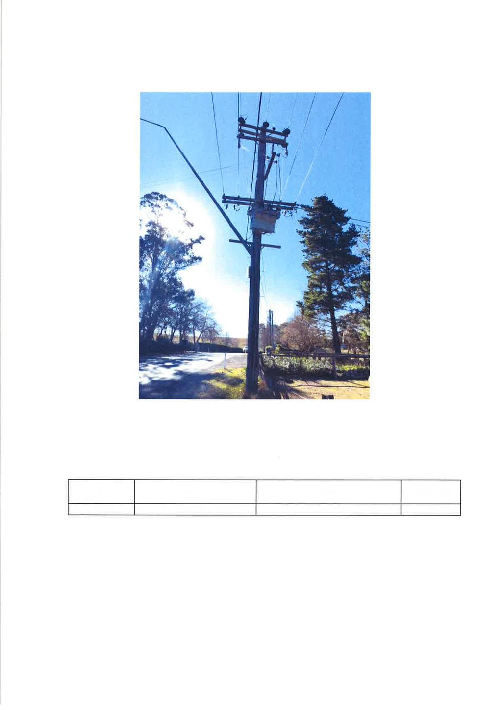
57
58
59

60

61