Ancillary Products. Hydroswell Bentostrip Method Statement
|
|
|
- Jane Bradford
- 5 years ago
- Views:
Transcription
![Ancillary Products Hydroswell Bentostrip Method Statement Application Procedures [Note: These instructions should be read in conjunction with the relevant product and safety data sheets] Hydroswell](/docs-images/95/123265921/images/1-0.jpg "Bentostrip is designed for sealing construction joints, cold joints and working joints in concrete, around pipe penetrations, in sewer joints, against slurry walls, sheet piling etc.")
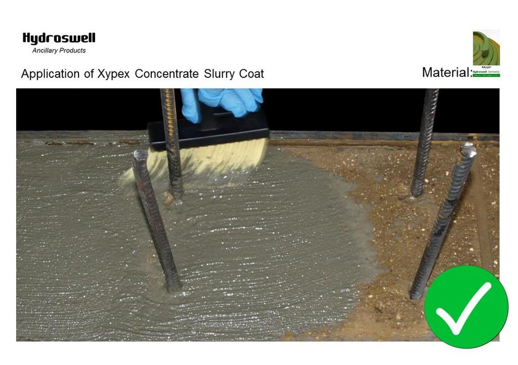
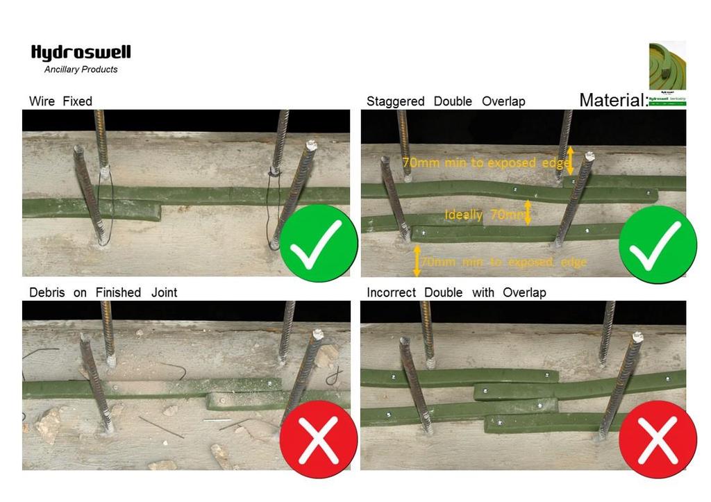
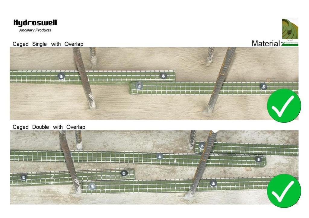
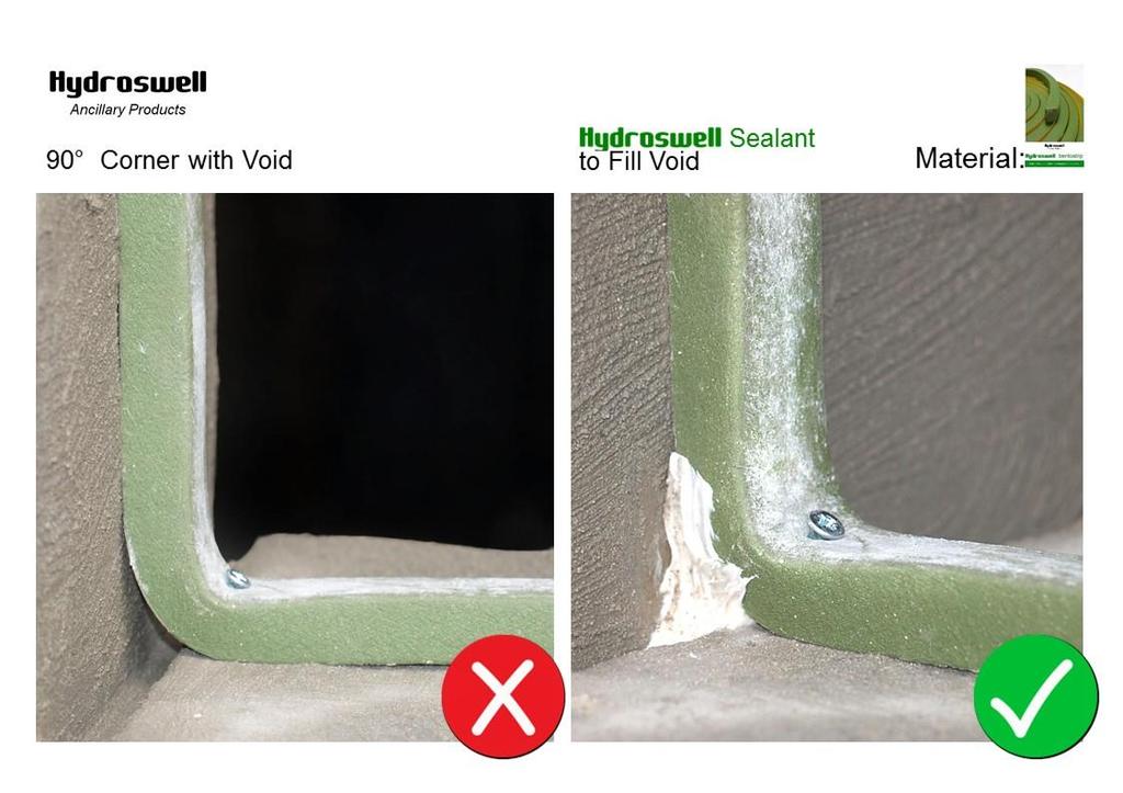
1 Ancillary Products Hydroswell Bentostrip Method Statement Application Procedures [Note: These instructions should be read in conjunction with the relevant product and safety data sheets] Hydroswell Bentostrip is designed for sealing construction joints, cold joints and working joints in concrete, around pipe penetrations, in sewer joints, against slurry walls, sheet piling etc. Surface Preparation The concrete surface must be clean and free from dust, dirt, oil, paint, or other foreign or loose substances that could hinder bond. Level very uneven and irregular surfaces by mechanical means or with Hydroswell Sealant. Application - Horizontal Applications Only Ensure Hydroswell Bentostrip has a minimum concrete cover of 70mm Unroll the Hydroswell Bentostrip strip ensuring the roll ends have a lateral overlap of 70mm and that the ends are pressed firmly together. Nail or gun nail the Hydroswell Bentostrip into place. Alternatively when there are two lines of reinforcing steel, tie wire can be fixed round the reinforcing steel and across the top of the Bentostrip to hold is securely in place. The minimum distance between tie wire fixing is 250mm. Installation during heavy rain or in prolonged contact with water should be avoided as this can result in a premature swelling of the strip. Hydroswell Bentostrip is applied during the installation of the 2nd phase reinforcement bars, in between inner and outer rows of tie bars. Application - Vertical and Inverted Applications Ensure Hydroswell Bentostrip has a minimum concrete cover of 70mm Unroll the Hydroswell Bentostrip strip ensuring the roll ends have a lateral overlap of 70mm and that the ends are pressed firmly together. Place the Hydroswell Bentosteel wire mesh profile over the Hydroswell Bentostrip. Fix the system by hammering or gun nailing using nails with a washer, at a rate of 4 nails per metre. Alternatively when there are two lines of reinforcing steel, tie wire can be fixed round the reinforcing steel and across the top of the Bentostrip to hold is securely in place. The minimum distance between tie wire fixing is 250mm. Installation during heavy rain or in prolonged contact with water should be avoided as this can result in a premature swelling of the strip Hydroswell Bentostrip is applied during the installation of the 2nd phase reinforcement bars, in between inner and outer rows of tie bars. Application Smooth steel surfaces (such as sheet piles) Ensure Hydroswell Bentostrip has a minimum concrete cover of 70mm. Apply an 8mm bead of Hydroswell Adhesive on to the surface of the sheet pile. Unroll the Bentostrip strip and press firmly into the glue. Wait until the glue has set before pouring concrete (a concrete cover of 70mm at all sides should always be respected). The roll ends should have a lateral overlapping 100mm. The ends need to be pressed firmly together. Additional nailing or gun nailing will provide secure fixing onto the concrete. Application Pipe Penetrations Ensure Hydroswell Bentostrip has a minimum concrete cover of 70mm Unroll the Hydroswell Bentostrip strip ensuring the roll ends have a lateral overlap of 100mm and that the ends are pressed firmly together. Page 1 of 2
2 Fix Hydroswell Bentostrip in place with steel wire ensuring it is secure and will not move during the placement of the concrete. Installation during heavy rain or in prolonged contact with water should be avoided as this can result in a premature swelling of the strip. Storage Hydroswell Bentostrip should be stored under cover, clear of the ground. Protect the materials from all sources of moisture and frost. Shelf life is unlimited. Storage temperature must be between 5 C and 30 C. Technical Data / Properties Swelling capacity in contact with water Swells approx. 400% of its original dry volume (*) Test report KUL University Density Approx. 1,44 kg/dm3 ASTM D71-84 Weight Approx. 0,72 kg/m Test DNC Cone penetration 35,5 ASTM D217 Expansion pressure under complete enclosure 0,70 N/mm2 Test report KUL University Resistance against hydrostatic pressure Up to 80 m water column = 8 bars Test report DNC Elongation at rupture 7500% Test method KUL University Maximum bend allowed No cracks at 180 above 0 C Test method KUL University Installation temperatures -15 C to 60 C Test DNC Operating temperatures -45 C to 120 C Test DNC Odour Odourless General These instructions for use are for general guidance purposes only. SMR Projects Ltd do not make any warranty as to the merchantability or fitness for a particular purpose. The user shall determine the suitability of the product for its intended use and assume all risks and liability in connection therewith. These Instructions for Use do not constitute as SMR Projects Ltd giving advice on a specific project or specification. This responsibility, and all risks and liability in connection therewith, remain with the user (or whoever is given such responsibility for the project in question.) For further detailed information relating to the use of this product, the user must refer to the Specification and Application Manual as well as the relevant technical data sheet. Any discrepancies between the manual or the data sheet and this document should be notified to a Xypex technical representative. A copy of the literature will be provided upon request. It is always recommended that before any application the local Xypex technical representative is contacted in order that he/she may assist the user in reviewing the proposed method of application, and perhaps advise of any further recommendations that may be required for the specific project in question. It is recommended that the user carry out trials and appropriate testing, under site conditions, prior to committing to using the product. This is not only to enable the user to determine the correct Xypex specification to be used, and confirm whether all the project specification requirements will be met, but also to ensure other issues, such as compatibility of products, are established. This document has been produced by SMR Projects Ltd and is subject to the standard terms and conditions of the Company, a copy of which are available upon request. v Page 2 of 2 SMR PROJECTS LIMITED Xypex House, Beaumont Close, Banbury, Oxfordshire, OX16 1TG Co Reg. No t e. info@smrxypex.co.uk w. smrxypex.co.uk VAT No
3
4
5
6
7