REPORT NUMBER: SAT-005 ORIGINAL ISSUE DATE: September 14, 2012 REVISED DATE: N/A
|
|
|
- Robyn Fields
- 5 years ago
- Views:
Transcription

1 TEST REPORT REPORT NUMBER: SAT-005 ORIGINAL ISSUE DATE: September 14, 2012 REVISED DATE: N/A EVALUATION CENTER Shady Falls Road Elmendorf, TX Phone: (210) Fax: (210) RENDERED TO United Plastics Corporation 511 Hay Street MOUNT AIRY NC PRODUCT EVALUATED: DB #4looring Material EVALUATION PROPERTY: Fire Resistance Report of Testing DB #4looring Material for compliance with the applicable requirements of the following criteria: ASTM E Standard Test Methods for Fire Tests of Building Construction and Materials, January 2012 Edition. This report is for the exclusive use of Intertek's Client and is provided pursuant to the agreement between Intertek and its Client. Intertek's responsibility and liability are limited to the terms and conditions of the agreement. Intertek assumes no liability to any party, other than to the Client in accordance with the agreement, for any loss, expense or damage occasioned by the use of this report. Only the Client is authorized to copy or distribute this report and then only in its entirety. Any use of the Intertek name or one of its marks for the sale or advertisement of the tested material, product or service must first be approved in writing by Intertek. The observations and test results in this report are relevant only to the sample tested. This report by itself does not imply that the material, product, or service is or has ever been under an Intertek certification program. 1
2 Report No SAT-005 Page 2 of 50 1 Table of Contents 1 Table of Contents Introduction Test Samples SAMPLE SELECTION SAMPLE AND ASSEMBLY DESCRIPTION Testing and Evaluation Methods INSTRUMENTATION TEST STANDARD Testing and Evaluation Results RESULTS AND OBSERVATIONS EXAMINATION OF RESULTS Conclusion...6 APPENDIX A - Name 8 APPENDIX B - Name 11 APPENDIX C - Name 24 LIST OF CALIBRATED INSTRUMENTATION 49 REVISION SUMMARY / LAST PAGE OF REPORT 50
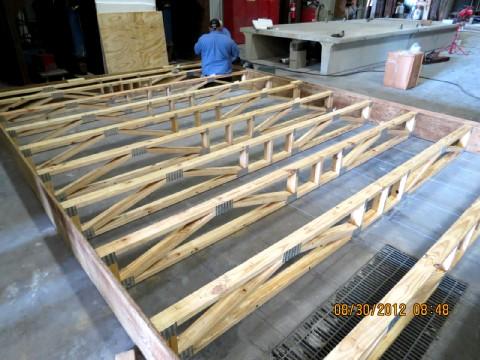
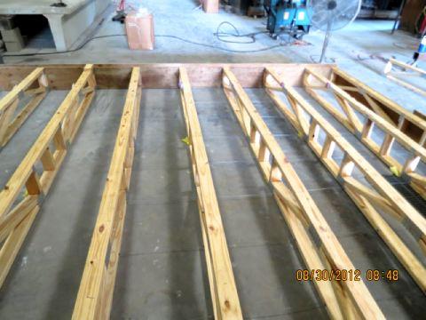
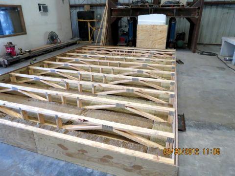
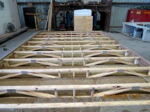
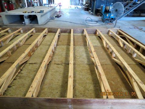
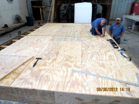
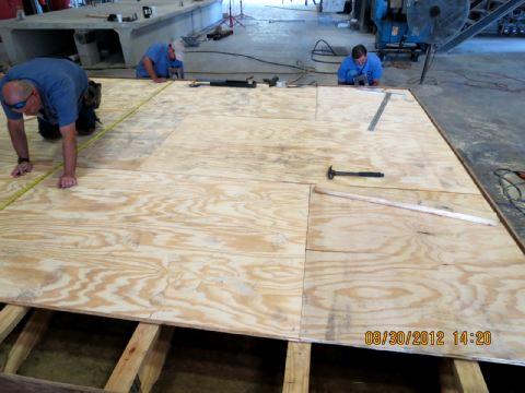
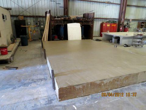
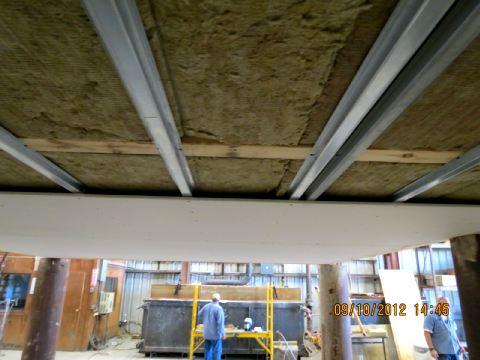
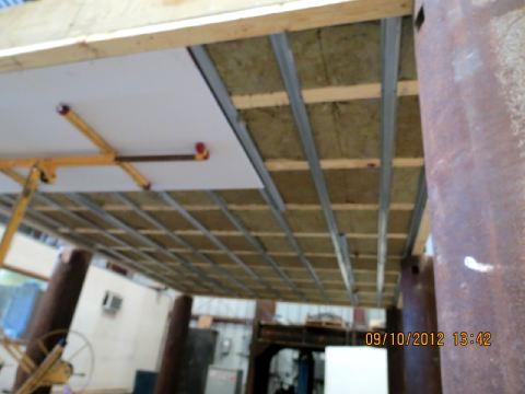
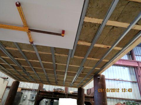
3 Report No SAT-005 Page 3 of 50 2 Introduction Intertek Testing Services NA, Inc. (Intertek) has conducted testing for United Plastics Corporation, on DB #4looring Material, to evaluate its fire resistance. Testing was conducted in accordance with the applicable requirements of, and following the standard methods of, ASTM E Standard Test Methods for Fire Tests of Building Construction and Materials, January 2012 Edition. This evaluation took place on September 11, Test Samples 3.1. SAMPLE SELECTION Samples were submitted to Intertek directly from the client. Samples were not independently selected for testing. Samples were received at the Evaluation Center on February 7, SAMPLE AND ASSEMBLY DESCRIPTION Intertek technicians constructed a 13 x 19 floor assembly using 12 deep wooden truss members, underlayment grade subflooring, a vapor barrier and a light weight concrete floor finish, insulation, furring channels and gypsum wallboard Framing 12 deep trusses spaced 24 o.c.: manufactured by Trussway Manufacturing Inc., Truss FF01 Floor Truss designed using Southern Yellow Pine 2x4 lumber. Two layers of 3/4" plywood were attached to the trusses to seal the perimeter of the sample. The plywood perimeter was attached using two 3-1/2 deck screws in the top and bottom chord of each truss. An additional 2 x 4 brace was installed in the center of each truss, secured with two #8d nails, top and bottom (see Appendix A). 2. Insulation 2 x 4 x 4 thick Thermafiber Safing Insulation batts (reported density 4pcf), compression fit into the space between trusses and supported by.090 diameter galvanized steel wires attached to the wood trusses, nominally 18 o.c. 3. Subflooring 23/32 thick, tongue & groove, underlayment-grade wood panels oriented with the grain perpendicular to the trusses with end joints staggered 4 ; secured to trusses using #6d ringed shank nails spaced 12 o.c. along each truss. 7
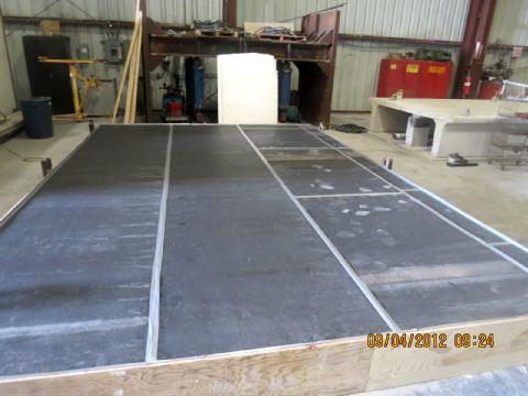
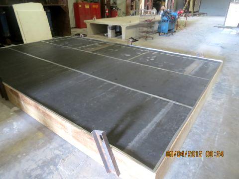
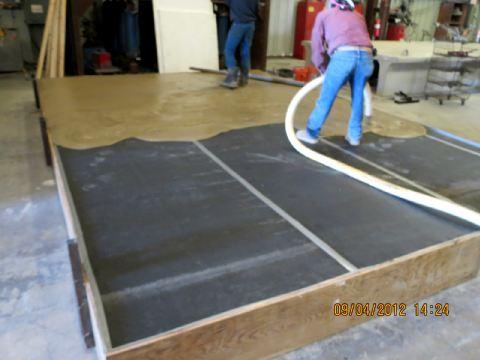
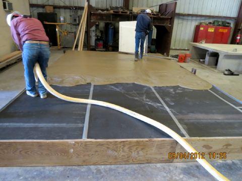
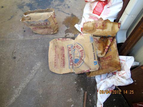
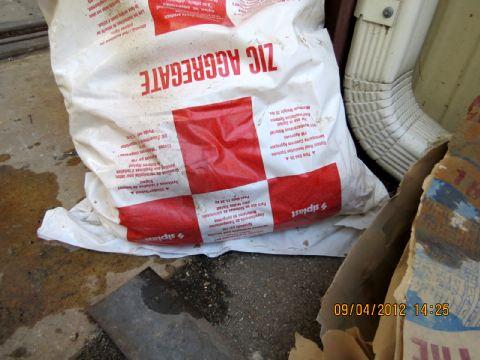
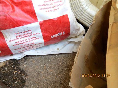
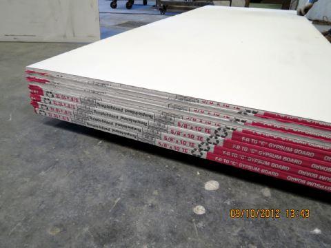
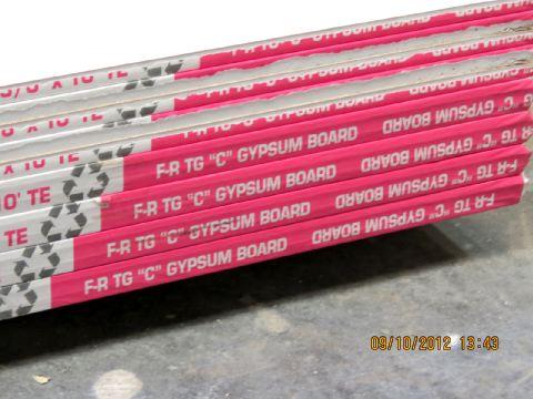
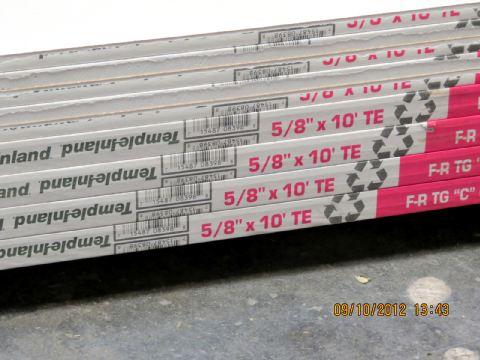
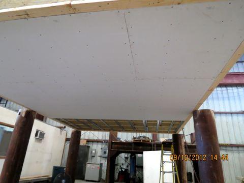
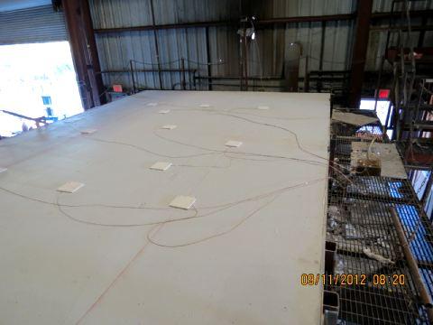
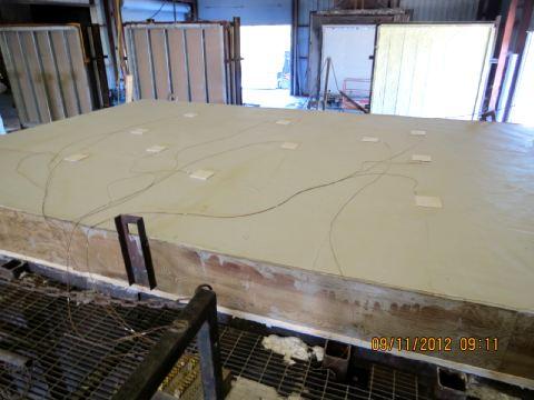
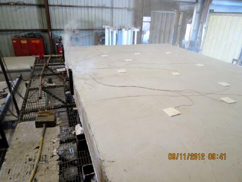
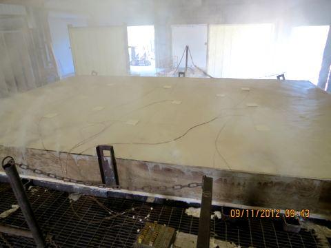
4 Report No SAT-005 Page 4 of Vapor Barrier 4 wide DB #4looring Material, installed fiber side down / rubber side up; strips butted together with duct tape over the butt joints. 5. Finish Flooring 3/4 thick lightweight insulating concrete mixture of normal weight Portland cement and vermiculite concrete aggregate in a 1:6 volume ratio; compressive strength average 90psi after 7 days; installed on September 4, 2012 by Drury South, Inc. 6. Furring Channels 7/8 deep x 2-11/16 wide at the base and 1-7/16 at the face, 25 GA galvanized steel, spaced 16 o.c. perpendicular to the trusses; secured to trusses using two #6 x 1-1/4 coarse thread screws at each truss. 7. Interior Cladding One layer of 4 x 10 x 5/8, Type C, Gypsum Board (Temple-Inland) installed with the long edge perpendicular to the furring channels, secured with #6 x 1 long Type S bugle head steel screws spaced 8 o.c. along the channels. All seams and fasteners received a Level 2 finish. 4 Testing and Evaluation Methods 4.1. INSTRUMENTATION The unexposed surface of the assembly was instrumented with a total of eleven (11), 24 GA, Type K, fiberglass jacketed thermocouples: TCs #1 9 were evenly distributed as described in the standard; TCs #10 and 11 were additional (see Appendix A). The output of the thermocouples and the furnace probes were monitored by a 300-channel Yokogawa, Inc., Darwin Data Acquisition Unit. The computer was programmed to scan and save data every 30 seconds. Following the test, the files were imported into MS Excel for tabular and graphical display (presented in Appendix B) TEST STANDARD Testing was conducted in accordance with the applicable requirements of, and following the standard methods of ASTM E Standard Test Methods for Fire Tests of Building Construction and Materials, January 2012 Edition. The assembly was secured to the large scale horizontal furnace and was tested to the standard time-temperature curve described in the E119 standard. 5 Testing and Evaluation Results 5.1. RESULTS AND OBSERVATIONS The test was initiated on Tuesday, September 11, The ambient temperature at the time of the test was 75 F and the relative humidity was 65%. There was no superimposed load for this test.
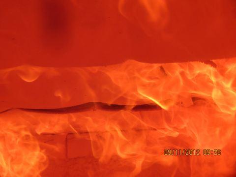
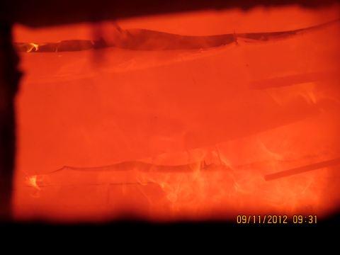
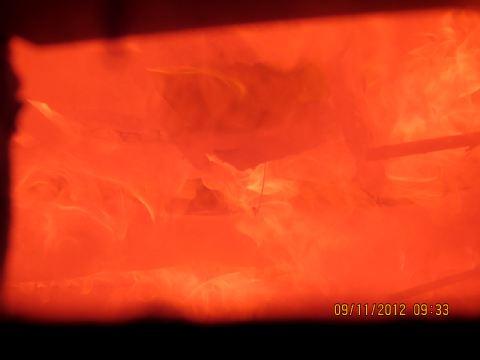
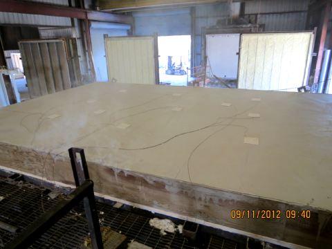
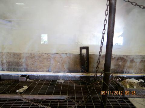
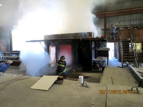
5 Report No SAT-005 Page 5 of 50 Observations made during the test are presented below: Time (min:sec) Observations 0:00 The test was initiated at 8:48 A.M. 3:20 The gypsum board paper on the exposed surface ignited 4:00 The gypsum board paper on the exposed surface was consumed 15:00 The joint tape and compound on the exposed surface began to flake 19:00 The joint tape and compound on the exposed surface were consumed 20:20 There were small flames at the joints of the exposed surface 27:00 Flaming had increased to moderate ; the gypsum board began to sag at the joints 31:30 There was approximately 1/2 shrinkage at the joints on the exposed surface 38:00 The gypsum board continued to sag; there were flames at the joints 41:00 The joints at the long edges of the gypsum board on the exposed surface continue to expand 46:00 The gypsum board on the exposed surface began to fall 48:00 All of the gypsum board had fallen from the sample 52:30 There was heavy flaming on the exposed surface of the sample 55:00 There were popping sounds from the sample; there was smoke from the perimeter at the unexposed surface 57:30 Heavy flaming continued on the exposed surface of the sample 59:00 There was visible deflection at the center of the sample 60:00 The burners were extinguished and the test was terminated The assembly withstood the effects of the fire test without passage of flame or gasses hot enough to ignite cotton waste. The heat conducted through the assembly did not cause the temperatures measured by the thermocouple to exceed the 250 F rise in average temperature or 325 F rise in individual temperatures over the initial starting temperatures. Assembly drawings, the test data and photographs documenting the test are located in the Appendices of this test report EXAMINATION OF RESULTS Correction Factor for the Fire Endurance Test In accordance with the E119 test standard, a calculation for any correction to the indicated fire resistance period was done. The correction factor was then mathematically added to the indicated fire resistance period, yielding the fire resistance period achieved by this specimen as shown on the next page.
6 Report No SAT-005 Page 6 of 50 Correction Factor for the Fire Endurance Test ITEM DESCRIPTION TEST VALUE C correction factor minutes -7 seconds I indicated fire-resistance period 60 minutes A area under the curve of indicated average furnace temperature for the first three fourths ( F min) of the indicated period As area under the standard furnace curve for the same part of the indicated period ( F min) ITEM DESCRIPTION TEST VALUE L lag correction 3240 FIRE RESISTANCE PERIOD ACHIEVED BY THIS SPECIMEN ==> 60 minutes Note: The standard specifies that the fire resistance be determined to the nearest integral minute. Consequently, if the correction factor is less than 30 seconds, and the test specimen met the criteria for the full indicated fire resistance period, no correction is deemed necessary. 6 Conclusion Intertek Testing Services NA, Inc. (Intertek) has conducted testing for United Plastics Corporation, on DB #4looring Material, to evaluate its fire resistance. Testing was conducted in accordance with the applicable requirements of, and following the standard methods of, ASTM E Standard Test Methods for Fire Tests of Building Construction and Materials, January 2012 Edition. This evaluation took place on September 11, Based on the results of this test, the assembly withstood the effects of the fire test and achieved a fire resistance rating of 60 minutes. The conclusions of this test report may not be used as part of the requirements for Intertek product certification. Authority to Mark must be issued for a product to become certified.


7 Report No SAT-005 Page 7 of 50 INTERTEK TESTING SERVICES NA, INC. Tested by: Joseph Zatopek Test Engineer Reported by: Michael A Brown Technical Writer Reviewed by: Victor M. Burgos Project Engineer, Fire Resistance
8 Report No SAT-005 Page 8 of 50 APPENDIX A Assembly Drawings
9 Report No SAT-005 Page 9 of 50 2 x4 section inserted in the center of the truss; secured using 2 X #8d nails top and bottom
10 Report No SAT-005 Page 10 of 50
11 Report No SAT-005 Page 11 of 50 APPENDIX B Temperature Data
12 Report No SAT-005 Page 12 of 50
13 Report No SAT-005 Page 13 of 50
14 Report No SAT-005 Page 14 of 50
15 Report No SAT-005 Page 15 of 50
16 Report No SAT-005 Page 16 of 50
17 Report No SAT-005 Page 17 of 50
18 Report No SAT-005 Page 18 of 50
19 Report No SAT-005 Page 19 of 50
20 Report No SAT-005 Page 20 of 50
21 Report No SAT-005 Page 21 of 50
22 Report No SAT-005 Page 22 of 50
23 Report No SAT-005 Page 23 of 50
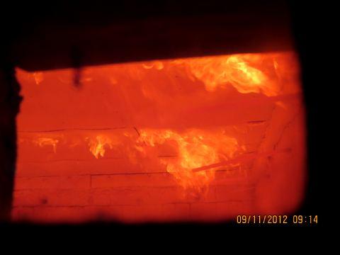
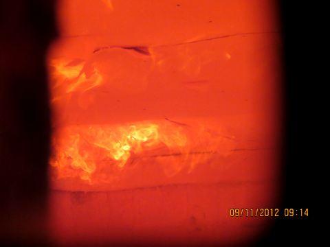
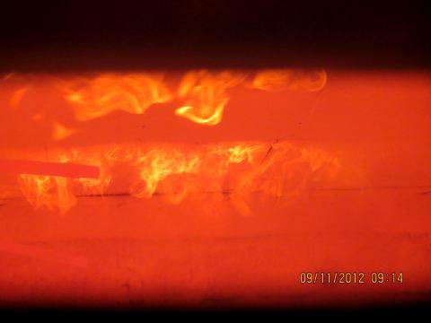
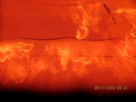
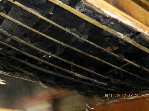
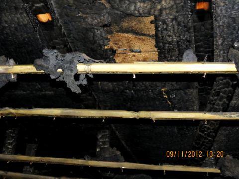
24 Report No SAT-005 Page 24 of 50 APPENDIX C Photographs
25 Report No SAT-005 Page 25 of 50
26 Report No SAT-005 Page 26 of 50
27 Report No SAT-005 Page 27 of 50
28 Report No SAT-005 Page 28 of 50
29 Report No SAT-005 Page 29 of 50
30 Report No SAT-005 Page 30 of 50
31 Report No SAT-005 Page 31 of 50
32 Report No SAT-005 Page 32 of 50
33 Report No SAT-005 Page 33 of 50
34 Report No SAT-005 Page 34 of 50
35 Report No SAT-005 Page 35 of 50

36 Report No SAT-005 Page 36 of 50
37 Report No SAT-005 Page 37 of 50
38 Report No SAT-005 Page 38 of 50
39 Report No SAT-005 Page 39 of 50
40 Report No SAT-005 Page 40 of 50
41 Report No SAT-005 Page 41 of 50


42 Report No SAT-005 Page 42 of 50
43 Report No SAT-005 Page 43 of 50
44 Report No SAT-005 Page 44 of 50
45 Report No SAT-005 Page 45 of 50
46 Report No SAT-005 Page 46 of 50

47 Report No SAT-005 Page 47 of 50
48 Report No SAT-005 Page 48 of 50
49 Report No SAT-005 Page 49 of 50 CALIBRATED INSTRUMENTATION USED FOR TESTING Description Serial No. Calibration Due Date Thermo-Hygrometer /2/ Channel Data Acquisition Unit 48JF0082 3/11/13 Stop watch /30/13
50 Report No SAT-005 Page 50 of 50 REVISION SUMMARY DATE September 14, 2012 SUMMARY Original Issue Date