h Installation Manual
|
|
|
- Allen Barker
- 6 years ago
- Views:
Transcription
1 h Installation Manual
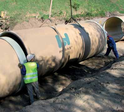
2 1 General Information The installation of HOBAS GRP Pipes is subject to applicable standards and guidelines such as EN 1610 and ISO/ TS Correct installation always requires individual calculations and comprehensive planning by certified engineers. In addition to all applicable standards and guidelines, engineers shall at all times consider all relevant conditions of the individual installation and operating situation of a certain project. All figures and recommendations included in this manual or provided by HOBAS are basic information regarding HOBAS Pipe Systems and do not represent a commitment with respect to individual projects. 2 Health and Safety Legal and local provisions as well as safety and accident prevention regulations must be observed and complied with at all times. 3 Support HOBAS offers different types of customized support based on individual service agreements. For further information please feel free to contact our HOBAS Experts. 4 Transport At the factory, all pipes are loaded to suit the means of transport (rail, truck, or ship). To economically transport pipes of different diameters, smaller diameter pipes may be nested inside larger ones. The loading of the pipes is performed with a forklift or crane, preferably using a coil boom. Pipes must be lifted individually with lifting slings or similar (do not use hooks!). On a level surface suitable rolls may be used as an alternative. 5 Storage It is recommended to stack pipes on a level surface to evenly distribute the load. Mechanical damage and soiling of the joint surfaces must be avoided. If required, wooden beams and wedges can be used.
3 6 Buried Pipelines The system stiffness is an important aspect of buried installations and determined by the pipe and soil stiffness. The pipeline must be carefully bedded as the soil around the pipe has a supporting function. 6.1 Pipe Trench The minimum trench depth depends on the loads that are applied on the pipeline (traffic load, thrust load from bends, etc.). In any case, it is necessary to choose an installation depth below the frost line. HOBAS Specialists offer assistance in calculating the installation depth for individual applications. The minimum trench width should be calculated according to EN Requirements of ISO/TS can also be used if applicable. 1. Installation of single pipe in trench according to EN 1610: Table 1: Minimum Trench Width (de + x) Diameter [mm] Supported trench [m] Unsupported trench [m] b > 60 b de de > 200 to 350 de de de > 350 to 700 de de de > 700 to 1200 de de de > 1200 de de de For the values de + x, the minimum working space between the x pipe and the trench wall or support equals 2. de... external diameter [m] b... angle of unsupported trench side measured to the horizontal [ ] 2. Installation of two pipes in trench; minimum trench width: de 0.5 m + de de de m Use of sheet piles during trench excavation; minimum trench width: de m or 3 de (the larger value is applicable)

4 1 b Surface 6 Pipe bedding 2 Main backfill 7 Trench depth 3 Initial backfill 8 Trench width at pipe bedding 4 Depth of embedment 9 Trench width at pipe crown 5 Sidefill 10 Trench bottom 6.2 Soil Quality Both the native soil and the bedding material must have a sufficient load-bearing capacity. If the load capacity of the excavated material is insufficient, it must be substituted by suitable bedding material (see 6.3. Trench Bottom and 6.4. Bedding and Backfilling). Table 2: Deformation Modulus E B (N/mm 2 ) and Degree of Compaction D Pr (%) Soil Types (acc. to ATV 127) D Pr = Group 1: Non-cohesive soil (e.g. gravel) Group 2: Slightly cohesive soil (e.g. sand) Group 3: Cohesive mixed soil (e.g. sand/clay mixture) Group 4: Cohesive soil (e.g. clay)
5 Table 3: Possible Cover Height (H) and Max. Allowable Initial Deformation (Def) SN 2500 SN 5000 SN Soil Types (acc. to ATV 127) H [m] Def H [m] Def H [m] Def Group 1: Non-cohesive soil (e.g. gravel) Group 2: Slightly cohesive soil (e.g. sand) Group 3: Cohesive mixed soil (e.g. sand/clay mixture) Group 4: Cohesive soil (e.g. clay) 4 < 4 % 8 < 4 % 12 < 4 % 3 < 4 % 5 < 4 % 7 < 4 % < 3.4 % 6 < 3.5 % < 3 % All figures shown above are non-binding examples. Each installation must be carried out on the basis of expert calculations and instructions. 6.3 Trench Bottom The trench bottom must be prepared in accordance with the required slope and installation depth of the pipe. The trench soil should not be loosened. If the soil is still loosened, suitable material must be added and evenly compacted. Any excavated material unsuitable for bedding the pipe and backfilling the trench should be stored separately. 6.4 Bedding and Backfilling With respect to the structural analysis of the installation, special attention has to be paid to the compaction of the bedding material. The thickness of the pipe bedding must be at least 15 cm or 0,1 x DN after compaction. With soft or unstable soils additional 15 cm of the soil should be replaced with e.g. soil type group 1 or 2. The pipe bedding must be tamped (e.g. with hand tamper or small pneumatic air tamper) and the entire length of the pipe must lie flat on the soil with the exception of the bell holes for the couplings. To ensure that the pipe sits flat on the base, bell holes measuring approximately three times the width of the coupling must be provided in the pipe joint area. Once the pipeline is bedded, the bell
6 Bell Hole holes must be backfilled with material of a comparable or higher degree of compaction. The bedding serves to apply a lateral soil pressure which relieves pressure on the pipeline. The bedding material must be inserted on both sides of the pipeline and backfilled up to a height of 30 cm above the top of the pipe. The material must be compacted on both sides simultaneously in order to prevent the pipeline from being displaced in any direction. If the soil is saturated with ground water or if aquifers are present, the material used for bedding and backfilling must be free of fines. In the sidefill and initial backfill zones the use of light vibro-tampers (max. service weight 30 kg) or light vibratory plates (max. service weight 100 kg) of an appropriate compaction depth is recommended. The following requirements apply regarding the bedding material: Perfectly compactable and sufficiently load-bearing, non-cohesive material If the material is compacted to a proctor compaction of 92 %, the minimum rigidity must be 3 N/mm 2 Depending on the diameter range, the below listed grain sizes should be used as bedding material: DN mm DN mm

7 Vibro-tamper, medium Service weight approx. 30 kg to compact the sidefill and initial backfill zone Service weight approx. 60 kg to compact the main backfill zone 0.3 m above the pipe crown The trench shall be refilled and backfilled in 30 cm layers. Each layer has to be compacted separately. The pipes must be stable and proper compaction achieved. The removal of sheet piles may have an effect on the pipe support. Therefore, sheet piles should be removed carefully and backfilling should be closely supervised. In the backfill zone between 0.3 and 1.0 m above the top of the main pipe the material can be compacted with a medium vibro-tamper (max. service weight 60 kg) or vibratory plate (max. service weight 500 kg). Heavy compaction equipment may be used beyond the 1 m mark above the top of the pipe. An underground warning tape should be provided. During the construction phase, major load transitions (use of e.g. heavy construction machinery or vehicles) should be avoided. 6.5 Pipe Handling Depending on the conditions on site, pipes up to DN 500 can be lowered into the trench manually. If a lifting gear is necessary, we recommend the use of lifting slings. Never attach hooks or chains as pipe ends may be damaged.


8 6.6 Pipe Jointing The pipes are delivered with one coupling mounted onto one pipe end. All parts of the pipe both its inner and outer surface must be cleaned and checked before the pipes are connected. The sealing elements of the couplings must be clean. A lubricant must be applied to the pipe ends and sealing elements (use only the lubricant supplied). Depending on the pipe dimensions, there are several possibilities to join the pipes: With a lever: With an appropriate pushing force: With an installation aid: E Group Worldwide HOBAS manufactures and markets HOBAS GRP Pipe Systems. The HOBAS Network includes HOBAS Production Facilities and Sales Organizations throughout the world. E Engineering GmbH Pischeldorfer Strasse Klagenfurt Austria T F info@hobas.com Published: 11/2014 All rights reserved. No part of this document may be reproduced or utilized in any form or by any means without our prior written permission. All information in the document is correct at the time of going to press. However, we reserve the right to make changes without notice, in particular to technical data. The data given is not binding and must therefore be checked in each individual case and revised as appropriate.
9 Various coupling types are available to join HOBAS Pipes. HOBAS Technicians will help determine the optimal coupling. Standard Couplings: FW Coupling/FWC (GRP coupling, EPDM/NBR gasket seal) DC Coupling (GRP coupling, EPDM gasket) Special Couplings: Restrained Pressure Pipe Joints (GRP coupling, locking element, EPDM/NBR gasket seal) Assembly Coupling, e.g. by Straub (stainless steel coupling, EPDM/NBR gasket) Adapter Coupling (GRP coupling, EPDM gasket) Sleeve Coupling, e.g. by FlexSeal (EPDM gasket) Masonry Coupling (GRP coupling) 6.7 Curved Installation Depending on the pipe diameter, HOBAS Couplings can accommodate the following degrees of angular deflection: Table 4: Angular Deflection Depending on the Pipe Diameter Diameter [mm] Maximum Allowable Deflection < to < to < Depending on the internal pressure and the angular deflection, it may be necessary to add suitable thrust blocks (concrete supports). a 6.8 Shored Trenches If the trench needs to be shored, the shores must be installed step by step as the trench is filled or compacted in layers. Trench subsidence influences the build-up of load above the pipes and should be avoided. When the shoring is removed, it is important to make sure the compacted backfill material ends flush with the native soil at the trench wall.
. 6.")


10 6.9 Pipe Length Adjustment On Site A circular saw can be used to cut HOBAS Pipes to length on site. After chamfering the trimmed end of the pipe, the coupling can be mounted using lubricant. No further finishing is required (no turning or similar) Installation of Fittings Fittings are joined similarly to standard pipes (e.g. with a cable pull). If elbows with a large angle are installed, suitable installation aids may be required to properly direct the force necessary for the jointing process. HOBAS can supply such installation aids. The incorporation of elbows, branches, reducers, or similar fittings produces thrust forces. The amount depends on the shape and the internal pressure. These forces must be directed into the soil by utilizing thrust blocks or suitable compaction of the backfill material. The forces can also be directed into the soil by friction between pipe and soil. Locked joints are necessary in this case. Thrust Blocks Tee: Bend: Reducer:
11 Calculation of the thrust force: RN N N a de N = P de² π 40 RN = N a a = 2 sin a 2 P... Test pressure [bar] de... External diameter [mm] N... Internal force [kn] RN... Resulting thrust force [kn] a... Factor for calculating the thrust force [-] a... Angular deflection [ ] When calculating the thrust force, the test pressure of the system should be taken into consideration. 7 Concrete Casing All HOBAS Pipe Types are suitable for concrete casing. The pipes shall be laid according to 6.1 to 6.10 and then secured against buoying upwards using round steel bows (at least three per 6-m pipe). Plastic putty shall be used to prevent cement slurry from entering the gap in DC couplings. Then the concrete can be cast layer by layer and has to be well compacted levelled. Do not use timber supports. 8 Above Ground Installation The design of the pipeline supports should correspond to the HOBAS Recommendations. The pipe supports should be placed at a distance of maximum 3 m. In most cases, a supporting angle of 120 and a cradle width of 20 cm will suffice. When designing the supports, the longitudinal and lateral forces must be taken into consideration.


12 Length A DN DN 1 A 1 B A-A 5 B Supports 2 Pipe 3 Coupling 4 Rubber strips 5 Fixation 9 Pressure Test A pressure test may be performed on properly bedded pipelines only. Before applying pressure, the line must be filled entirely with water. The test pressure should be max. 1.5 times the nominal pressure of the pipe or the nominal pressure + 5 bar. The lower of these two pressure values is applicable. The max. duration of the pressure test is recommended to be 1 hour. The end caps must be carefully secured so they can withstand the forces. 10 Other Installation Methods HOBAS Pipes can be installed by various methods, e.g. open cut, above ground, under water, relining, and jacking. Ask our HOBAS Technicians for further information or visit the HOBAS Website. HOBAS. Make things happen.
h GRP Pipe Systems Transportation, Installation & Maintenance
 h GRP Pipe Systems Transportation, Installation & Maintenance Contents 1 Introduction... 1 2 Transportation & Unloading of Pipes, Manholes, and Fittings... 2 3 Storage... 4 4 Installation... 6 5 Mounting
DUCTILE IRON PIPES AND FITTINGS DETAILED PRODUCTS SPECIFICATIONS
 DUCTILE IRON PIPES AND FITTINGS DETAILED PRODUCTS SPECIFICATIONS General All Materials shall be EN, ISO or equivalent standard and shall be supplied from approved manufacturers. According to the International
TABLE OF CONTENTS
 DIVISION 33: SEWER AND SEPTIC SYSTEMS 33 3633 UTILITY SEPTIC TANK DRAINAGE FIELD TABLE OF CONTENTS 33 0000-1 SECTION 33 3633-- UTILITY SEPTIC TANK DRAINAGE FIELD PART 1 - GENERAL 1.1 SUMMARY A. Includes
Saudi Vitrified Clay Pipe Co.
 Saudi Vitrified Clay Pipe Co. Practical tips for laying V.C.Pipes professionally Table of contents: 1. Unloading of the truck 2. Storage on site 3. Transportation to the pipe trench 4. Installation 5.
Installation Instructions for Circular Trench Pipes (DN300 DN1200) PD 46 rev D October 2013
 PD 46 rev D October 2013") Installation Instructions for Circular Trench Pipes (DN300 DN1200) October 2013 Page 1 of 7 1. Scope This document gives basic guidance on the installation of Stanton Bonna circular pipes incorporating
Installation Instructions for Circular Trench Pipes (DN300 DN1200) October 2013 Page 1 of 7 1. Scope This document gives basic guidance on the installation of Stanton Bonna circular pipes incorporating
HEKAPLAST. PE-HD twin wall cable ducts and cable protection pipes for underground installation. Corrugated and Twin Wall Pipes of Plastics
 HEKAPLAST PE-HD twin wall cable ducts and cable protection pipes for underground installation HEGLER HEKAPLAST III/ HEKAPLAST: Twin wall cable ducts or cable protection pipes to DIN 696, manufactured from
San Antonio Water System Standard Specifications for Construction ITEM NO. 848 SANITARY SEWERS
 ITEM NO. 848 SANITARY SEWERS 848.1 DESCRIPTION: This item shall govern the furnishing, installation and jointing of sanitary sewer pipe of the size and type specified by the project's plans and specifications.
VALLECITOS WATER DISTRICT SECTION POLYVINYL CHLORIDE (PVC) PRESSURE PIPE
 PRESSURE PIPE") PART 1 - GENERAL 1.1 DESCRIPTION A. This section designates the requirements for the manufacture and installation of polyvinyl chloride, abbreviated PVC, pressure pipe. 1.2 RELATED WORK SPECIFIED ELSEWHERE
PART 1 - GENERAL 1.1 DESCRIPTION A. This section designates the requirements for the manufacture and installation of polyvinyl chloride, abbreviated PVC, pressure pipe. 1.2 RELATED WORK SPECIFIED ELSEWHERE
SPECIFICATION FOR REINFORCED SOIL WALL
 SPECIFICATION FOR REINFORCED SOIL WALL 1.0 EXTENT OF WORK The work shall consist of Reinforced Soil walls built in accordance with this specification and in conformity with the lines, levels and details
Althon slot channels Althon
 Effectively innovative. Althon slot channels - the solid drainage system! Althon slot channels Althon Drainage systems Althon slot channels high resilience high performance! The Althon slot channel is
Precast Concrete Trench Drain Systems INSTALLATION INSTRUCTIONS
 Precast Concrete Trench Drain Systems INSTALLATION INSTRUCTIONS GENERAL INSTALLATION INSTRUCTIONS 1 Ensure that the trench where the channels are going to be installed has enough room for the appropriate
Technical Data Sheet NEC/GRAN/95:01
 Technical Data Sheet NEC/GRAN/95:01 Installation Guidance Notes Granular Surround Note : These guidance notes refer only to the installation of Granular surround underground tanks. These guidance notes
SECTION 19 - TRENCH EXCAVATION, BEDDING AND BACKFILL TABLE OF CONTENTS
 SECTION 19 - TRENCH EXCAVATION, BEDDING AND BACKFILL TABLE OF CONTENTS Section Page 19-1 TRENCH EXCAVATION...19.1 19-1.01 Exploratory Excavation...19.1 19-1.02 Trench Width...19.1 19-1.02.A Storm Drain
PVC Fittings & Laterals for Solid-Wall PVC Sewer Pipe
 Design and Installation Guide PVC Fittings & Laterals for Solid-Wall PVC Sewer Pipe TABLE OF CONTENTS Introduction 2 Products 3 Main-Line Fittings & Service-Line Fittings 3-4 Connections to Dissimilar
1993 SPECIFICATIONS CSJ SPECIAL SPECIFICATION ITEM 4110 CONCRETE ENCASED DUCT BANK
 1993 SPECIFICATIONS CSJ 581-1-95 SPECIAL SPECIFICATION ITEM 4110 CONCRETE ENCASED DUCT BANK 1. DESCRIPTION. This Item shall govern for the furnishing and installation of all materials and equipment for
freestone eco Prestige & quality DIY vertical wall Large blocks - 10/m 2 Smooth surface finish No concrete footings
 freestone eco Retaining Wall SystemTM The Freestone ECO Retaining Wall System TM is a more sustainable DIY, vertical retaining wall which is manufactured with up to 40% recycled glass aggregate to provide
SECTION DUCTILE IRON FITTINGS. A. This section includes materials, installation, and testing of ductile iron fittings 48 inches and smaller.
 PART 1 - GENERAL 1.1 DESCRIPTION A. This section includes materials, installation, and testing of ductile iron fittings 48 inches and smaller. 1.2 RELATED WORK SPECIFIED ELSEWHERE A. Section 01300 Record
Installation Data for Elliptical Pipes. PD 29 rev E 20/09/05
 Installation Data for Elliptical Pipes 20/09/05 Page 1 of 10 1. Scope This document gives basic guidance on the installation of Stanton Bonna Ellipitical pipes under normal conditions. When circumstances
TCC/SHORE TRANSIT BUS MAINTENANCE FACILITY - PHASE II
 SECTION 221313 - FACILITY SANITARY SEWERS PART 1 - GENERAL 1.1 RELATED DOCUMENTS A. Drawings and general provisions of the Contract, including General and Supplementary Conditions and Division 01 Specification
DISTRIBUTED BY EMPIRE INFRASTRUCTURE PTY LTD
 DISTRIBUTED BY EMPIRE INFRASTRUCTURE PTY LTD Contents Introduction Applications Standards Quality Classification Product Range Jacking Pipes Relining Pipes Introduction The company The process We are proud
Reinforced concrete slot channel
 Applicable Bodies of Rules: DIN EN 1433»Drainage channels for vehicular and pedestrian areas«din 19580»Drainage channels for vehicular and pedestrian areas«the following laying instructions are general
Handling and Installation Instructions
 Handling and Installation Instructions SUPERTANK Water Reclamation Solutions, LLC Unloading and Handling NOTE: It is the responsibility of the installer to follow OSHA safety guidelines during the installation,
A. Product Data: For surface pathways, wireways and fittings, floor boxes, hinged-cover enclosures, and cabinets.
 ALLIANT ENERGY CENTER PAVILIONS Project No. 2013 027 SECTION 27 05 28 - PART 1 - GENERAL 1.1 RELATED DOCUMENTS A. Drawings and general provisions of the Contract, including General and Supplementary Conditions
SECTION 19 - TRENCH EXCAVATION, BEDDING AND BACKFILL TABLE OF CONTENTS
 SECTION 19 - TRENCH EXCAVATION, BEDDING AND BACKFILL TABLE OF CONTENTS Section Page 19-1 TRENCH EXCAVATION... 19.1 19-1.01 Exploratory Excavation... 19.1 19-1.02 Trench Width... 19.1 19-1.02.A Storm Drain
STRAIL level crossing systems & STRAILastic track damping systems
 pontistrail - installation instructions Subject to technical changes / February 2010 STRAIL level crossing systems & STRAILastic track damping systems Gummiwerk KRAIBURG Elastik GmbH / D-84529 Tittmoning
CORRUGATED DRAINAGE PIPES FOR DRAINING UNDERGROUND AND SURFACE RUNOFF WATER 01 / 2017 CATALOGUE
 TERRAIN DRAINAGE CORRUGATED DRAINAGE PIPES FOR DRAINING UNDERGROUND AND SURFACE RUNOFF WATER 01 / 2017 CATALOGUE 2 CERTIFICATES OF QUALITY 3 Description of the system All modern projects are carried out
Top Performance Pipes for Toughest Conditions
 h Top Performance Pipes for Toughest Conditions 2 Corrosion, Abrasion, Impacts: Customized Solutions for the Most Challenging Applications h Top Performance Pipe Systems When aggressive materials are transported
CONNECTION TO INSPECTION CHAMBERS PRAKTO
 CONNECTION TO INSPECTION CHAMBERS PRAKTO The inspection chambers PRAKTO made by Pipelife are designed and manufactured to be conveniently and securely connected to pipes and fittings of the Pragma series
ASSEMBLY AND OPERATING MANUAL LTW SLIDE RAIL SYSTEM - Type FP
 Manufacturer: LTW Tiefbauvertriebs GmbH Holter Weg 11 D 41836 Hückelhoven-Brachelen Phone: +49 (0) 24 62 / 2009 0 Fax: +49 (0) 24 62 / 2009 15 e-mail: info@ltw-verbau.de homepage: http:\ \ www.ltw-shoring.com
Tasman Retaining Wall System
 Tasman Retaining Wall System The Tasman Retaining Wall System incorporates purpose made corners and capping units to provide classical reconstructed stone retaining walls for any landscape situation. From
San Antonio Water System Standard Specifications for Construction ITEM NO. 813 WATER SERVICE FOR FIRELINES
 ITEM NO. 813 WATER SERVICE FOR FIRELINES 813.1 DESCRIPTION: This item shall consist of water service for fire line installations in accordance with these specifications and as directed by the Engineer.
SECTION SANITARY UTILITY SEWERAGE PIPING
 SECTION 33 31 00 SANITARY UTILITY SEWERAGE PIPING PART 1 GENERAL 1.1 SUMMARY A. Section Includes: 1. Sanitary sewer pipe and fittings. 2. Underground pipe markers. 3. Connection to existing manholes. 4.
INDEX FOR SPECIFICATIONS FOR REMOVING CULVERTS AND PLACING CULVERTS SCOPE... 1
 March 2002 No. 400 INDEX FOR SPECIFICATIONS FOR REMOVING CULVERTS AND PLACING CULVERTS 400. 1 SCOPE... 1 400. 2 REMOVING CULVERTS AND TIMBER STRUCTURES 2.1 Concrete and Metal Pipe Culverts... 1 2.2 Structural
SECTION STORM DRAINAGE
 SECTION 02720 STORM DRAINAGE PART 1 - GENERAL 1.01 WORK INCLUDED A. Trenching and other excavation. B. Ground water control. C. Pipe bedding. D. Installation of storm drains and appurtenances. E. Installation
ITEM 460 REINFORCED CONCRETE PIPE Description. This Item shall govern for the furnishing of reinforced concrete pipe.
 AFTER MARCH 1, 2012 ITEM 460 REINFORCED CONCRETE PIPE 460.1 Description. This Item shall govern for the furnishing of reinforced concrete pipe. 460.2 Materials. A. Except as modified herein, materials,
Multi-Gard PVC Assembly/ Field Cuts
 Multi-Gard PVC Assembly/ Field Cuts Assembly 1. Distribute Multi-gard sections along the sides of the trench with male ends pointing towards starting vault entrance.. Remove protective cap and install
Assembly and Installation Instructions Grease Separator KLsepa.pop
 Assembly and Installation Instructions Grease Separator KLsepa.pop It is imperative to observe the items described in these instructions. In case of noncompliance, all warranty claims shall lapse. For
 Preparation & Jointing Doing Prevents Align bell and spigot of pipes to be joined. Before homing the joint, check that the gasket is in contact with the entry taper around the entire circumference Make
***************************************************************************************************************
 02732 SANITARY FORCE MAIN *************************************************************************************************************** SPECIFIER: CSI MasterFormat 2004 number 33 34 00. ***************************************************************************************************************
Retaining Wall System
 Your local distributor Retaining Wall System Prestige & Quality Near Vertical Walls Do It Yourself No Concrete Footings Flexible - 90 o Corners, Steps, Straight or Curved Walls Commercial or Civil Walls
Section 2 Specification 2.18 Concrete and/or Corrugated Steel Storm Sewer TABLE OF CONTENTS
 TABLE OF CONTENTS 2.18 CONCRETE AND/OR CORRUGATED STEEL STORM SEWER... 1 2.18.1 GENERAL... 1 2.18.2 MATERIALS... 1 2.18.2.1 Storm Sewer Pipe... 1 2.18.2.2 Cement Mortar... 1 2.18.2.3 Granular Materials...
Perfect Manhole Installation Manual May 2012 Rev 8 Perfect Manhole System Precast concrete manholes with load bearing elastomeric joints
 Perfect Manhole System Precast concrete manholes with load bearing elastomeric joints Installation Manual 1 1 Introduction This manual gives guidance on how to install the CPM Group Perfect manhole system
innostrail - installation instructions Subject to technical changes / January 2010 STRAIL level crossing systems & STRAILastic track damping systems
 innostrail - installation instructions Subject to technical changes / January 2010 STRAIL level crossing systems & STRAILastic track damping systems gummiwerk kraiburg elastik gmbh / D-84529 Tittmoning
PVC pressure pipe (grey)
") PVC pressure pipe (grey) PVC pressure pipe is used for the transport of liquids under pressure. The product range is divided into various pressure classes that indicate the maximum working pressure. The
PVC pressure pipe (grey) PVC pressure pipe is used for the transport of liquids under pressure. The product range is divided into various pressure classes that indicate the maximum working pressure. The
INDEX FOR SPECIFICATIONS FOR JACKING CULVERTS THROUGH EMBANKMENTS SCOPE... 2
 INDEX FOR SPECIFICATIONS FOR JACKING CULVERTS THROUGH EMBANKMENTS 410. 1 SCOPE... 2 410. 2 DEFINITIONS 2.1 Tunneling and Jacking... 2 2.2 Tunneling... 2 2.3 Jacking... 2 410. 3 MATERIALS 3.1 General...
UNDERGROUND UTILITY CONTRACTORS GENERAL TRADE KNOWLEDGE EXAMINATION CONTENT INFORMATION
 UNDERGROUND UTILITY CONTRACTORS GENERAL TRADE KNOWLEDGE EXAMINATION CONTENT INFORMATION Effective September 9, 2014 The General Trade Knowledge portion of the examination is administered daily in Computer
Strengthened Soil Wall Construction Manual
 Strengthened Soil Wall Construction Manual This information has been prepared by Shaw Technologies, Inc. as an aid in constructing their Strengthened Soil Wall system. Final determination of the suitability
ITEM NO SLIPLINING SANITARY SEWERS
 ITEM NO. 1100 SLIPLINING SANITARY SEWERS 1100.1 DESCRIPTION: Sliplining is accomplished by pulling or pushing liner pipe into existing sewers by use of mechanical or hydraulic equipment. Once in place,
SECTION A1 EXCAVATION AND BACKFILL GENERAL
 SECTION A1 EXCAVATION AND BACKFILL GENERAL The work under this section shall include all excavation to such width and depth as shown on the drawings, specified herein, or ordered by the Engineer. Such
SECTION 19 - TRENCH EXCAVATION, BEDDING AND BACKFILL TABLE OF CONTENTS
 SECTION 19 - TRENCH EXCAVATION, BEDDING AND BACKFILL TABLE OF CONTENTS Section Page 19-1 TRENCH EXCAVATION... 19.1 19-1.01 Exploratory Excavation... 19.1 19-1.02 Trench Width... 19.1 19-1.02.A Storm Drain
SECTION EXCAVATION AND BACKFILL FOR UTILITIES AND STRUCTURES
 SECTION 02215 EXCAVATION AND BACKFILL FOR UTILITIES AND STRUCTURES PART 1 - GENERAL 1.1 DESCRIPTION: This section includes materials, testing, and installation of earthwork for excavations, fills, and
This section includes materials and installation of ductile-iron pipe and fittings for potable and recycled water systems.
 NORTH MARIN WATER DISTRICT STANDARD SPECIFICATIONS SECTION 15056 DUCTILE-IRON PIPE AND FITTINGS PART 1 GENERAL 1.01 DESCRIPTION This section includes materials and installation of ductile-iron pipe and
San Antonio Water System Standard Specifications for Construction ITEM NO. 812 WATER MAIN INSTALLATION
 ITEM NO. 812 WATER MAIN INSTALLATION 812.1 DESCRIPTION: This item shall consist of water main installation in accordance with these specifications and as directed by the Engineer. 812.2 MATERIALS: The
Tasman Retaining Wall System
 Tasman Retaining Wall System The Tasman Retaining Wall System incorporates purpose made corners and capping units to provide classical reconstructed stone retaining walls for any landscape situation. From
SECTION UTILITY POLYETHYLENE CONTAINMENT PIPE SYSTEMS
 SECTION 02670 UTILITY POLYETHYLENE CONTAINMENT PIPE SYSTEMS PART 1 - GENERAL 1.01 WORK INCLUDED A. Trenching and other excavation. B. Ground water control. C. Pipe bedding. D. Installation of containment
Innovation in Joint Restraint Systems for PVC Pressure Pipe and Fittings. Clean & Safe Drinking Water Workshop. Wednesday, March 25, 2015
 Innovation in Joint Restraint Systems for PVC Pressure Pipe and Fittings Clean & Safe Drinking Water Workshop Wednesday, March 25, 2015 Thrust forces Gasketed joints are made to seal and not to restrain,
ITEM D-701 PIPE FOR STORM DRAINS AND CULVERTS
 ITEM D-701 PIPE FOR STORM DRAINS AND CULVERTS 701-1 DESCRIPTION 701-1.1 This item shall consist of the construction of pipe culverts, and storm drains, removal of existing storm pipes, connections to existing
UPONOR INFRASTRUCTURE. Uponor Gravity Sewer Systems 47
 UPONOR INFRASTRUCTURE Uponor Uponor 47 Uponor Gravity Drainage and Sewer 5.1 Introduction...50 Sewer System Planning & Design...52 Sewer System Flow Design...59 Installation General Instructions and Supervision...62
DOUBLE SLIDE RAIL INSTALLATION METHOD. Double Slide Rail August
 Double Slide Rail August 2015 1 DOUBLE SLIDE RAIL INSTALLATION METHOD Introduction Slide rail shoring systems can be used for trenches up to 12m wide and 6m deep. Module length is determined by panels
STRAIL - installation instructions. Subject to technical changes / December STRAIL level crossing systems & STRAILastic track damping systems
 STRAIL - installation instructions Subject to technical changes / December 2009 STRAIL level crossing systems & STRAILastic track damping systems Gummiwerk KRAIBURG Elastik Gmbh / D-85429 Tittmoning Goellstrasse
Chapter 10. Pipeline Installation
 Chapter 10 CHAPTER 10 STOCKWATER PIPELINE INSTALLATION TABLE OF CONTENTS PART 10.1 TRENCHING 10-1 10.1.1 Backhoe Constructed Trench 10-1 10.1.2 Trencher Constructed Trench 10-1 10.1.3 Backfilling and Maintenance
Installation and maintenance instructions for GRAF rainwater storage tank, Carat-S series
 Distributed by: info@graf-online.de Installation and maintenance instructions for GRAF rainwater storage tank, Carat-S series 2700 Litres / 700 US-gallons Order No. 372001 3750 Litres / 1000 US-gallons
GROUNDtrax GROUNDGRIDZ
 INSTALLATION GUIDE The product is asymmetric and must be lifted by placing the hands on the diagonally opposed corners of the central paver (as shown). 1. Place grids onto the prepared well consolidated
ASSEMBLY AND OPERATING MANUAL LTW SLIDE RAIL SYSTEM - Type PV
 Manufacturer: LTW Tiefbauvertriebs GmbH Holter Weg 11 D 41836 Hückelhoven-Brachelen Phone: +49 (0) 24 62 / 2009 0 Fax: +49 (0) 24 62 / 2009 15 e-mail: info@ltw-verbau.de homepage: http:\ \ www.ltw-shoring.com
for potable water supply
 UPONOR INFRASTRUCTURE Uponor System PVC Uponor System PVC for potable water supply Uponor System PVC 209 6.3 Uponor System PVC Characteristics The Uponor System PVC is designed for potable water distribution,
R-Group Finland Oy. RTA, RWTL and RWTS Lifting anchors Design instructions
 R-Group Finland Oy RTA, RWTL and RWTS Lifting anchors Design instructions According to Eurocodes, EU Machinery directive 2006/42/EC and VDI/BV-BS 6205 CE Approved 28.12.2016 2 Table of contents 1 DESCRIPTION
FREESTONE ECOTM. Retaining Wall SystemTM. No one knows Blocks and Pavers better
 FREESTONE ECOTM Retaining Wall SystemTM The Freestone ECO Retaining Wall System TM is a more sustainable DIY, vertical retaining wall which is manufactured with up to 40% recycled glass aggregate to provide
SECTION TRENCHING, BACKFILLING, COMPACTION AND GENERAL GRADING
 PART 1 GENERAL SECTION 02221 TRENCHING, BACKFILLING, COMPACTION AND GENERAL GRADING 1.01 SECTION INCLUDES A. Excavation, dewatering and backfilling with compaction of trenches for pipes, conduits, channels
Employment Intensive Infrastructure Program (EIIP) in Lebanon ANNEX 2
 in Lebanon ANNEX 2") Employment Intensive Infrastructure Program (EIIP) in Lebanon ANNEX 2 PARTICULAR SPECIFICATIONS FOR THE CONSTRUCITON OF STORM WATER DRAINAGE NETWORK March 2018 BUREAU TECHNIQUE POUR LE DEVELOPPEMENT P.O.B
Employment Intensive Infrastructure Program (EIIP) in Lebanon ANNEX 2 PARTICULAR SPECIFICATIONS FOR THE CONSTRUCITON OF STORM WATER DRAINAGE NETWORK March 2018 BUREAU TECHNIQUE POUR LE DEVELOPPEMENT P.O.B
INSTALLATION AND BURIAL OF GRP PIPES MANUAL
 INSTALLATION AND BURIAL OF GRP PIPES MANUAL 1 CONTENTS 1. Foreword 4 1.2 Safety 4 2. Transport 5 3. Handling and unloading 6 3.1 Single pipes 6 3.2 Unitised loads 6 3.3 Nested pipes 6 4. Storage 8 5. Inspection
CONCRETE PIPES CONCRETE PIPES FACTORY. Since Concrete. Slabs (Cover) for Cable. Trench Jacking. Jacking Pipes. Non & Reinforced. without.
 for Cable. Trench Jacking. Jacking Pipes. Non & Reinforced. without.") CONCRETE PIPES Gullies Manholes Intermediate Jacking s with Steel Sleeve Non & Reinforced Concrete s Concrete Slabs (Cover) for Cable Half Round Wheel Stopper Trench Jacking CONCRETE PIPES FACTORY Since
CONCRETE PIPES Gullies Manholes Intermediate Jacking s with Steel Sleeve Non & Reinforced Concrete s Concrete Slabs (Cover) for Cable Half Round Wheel Stopper Trench Jacking CONCRETE PIPES FACTORY Since
NOVEMBER 2016 GRANDWALL. retaining walls installation guide
 NOVEMBER 2016 GRANDWALL retaining walls installation guide RETAINING WALL INSTALLATION GUIDE RETAINING WALL information Austral Masonry Grandwall retaining wall blocks are an ideal choice for retaining
NEMO TANK INSTALLATION GUIDE INSTALLATION INSTRUCTIONS FOR THE NEMO TANK STAGE
 NEMO TANK INSTALLATION GUIDE INSTALLATION INSTRUCTIONS FOR THE NEMO TANK STAGE 1. Before undertaking the work 2. Receiving the materials 3. Handling and storage 4. Tank layout 5. Installing the tanks STAGE
TS 803 DUCTS DUCT INSTALLATION, PROTECTION AND MARKING WITHIN A TRENCH OPEN TRENCH DUCT INSTALLATION PROFILE
 TORONTO TRANSPORTATION March 2012 TS 803 DUCTS TABLE OF CONTENTS 1. DRAWINGS TTD 803.001 TTD 803.010 DUCT INSTALLATION, PROTECTION AND MARKING WITHIN A TRENCH OPEN TRENCH DUCT INSTALLATION PROFILE 2. CONSTRUCTION
UNIVERSITY OF MISSOURI Hydronic Energy Distribution 2016 Q1
 GENERAL: The scope of this document is to provide instruction for the installation and testing of chilled water piping installed for the University of Missouri. DESIGN GUIDELINES: 1. Materials 1.1. Pipe
Single-skin, externally reinforced, brick tank. Instructions for manufacture
 Single-skin, externally reinforced, brick tank Instructions for manufacture Development Technology Unit School of Engineering University of Warwick Coventry CV4 7AL Tel: +44 (0)1203 522339 Fax: +44 (0)1203
Installation Guide for Precast Concrete Culverts
 Installation Guide for Precast Concrete Culverts PD90 Rev D Contents 1.0 Scope of guide 2.0 Receipt of goods 3.0 Handling and storage of the products 3.1 Handling 3.2 Attaching clutch 3.3 Lifting 3.4 Storage
CONSTRUCTION SPECIFICATION FOR PRECAST REINFORCED CONCRETE BOX CULVERTS AND BOX SEWERS IN OPEN CUT
 ONTARIO PROVINCIAL STANDARD SPECIFICATION METRIC OPSS 422 APRIL 2004 CONSTRUCTION SPECIFICATION FOR PRECAST REINFORCED CONCRETE BOX CULVERTS AND BOX SEWERS IN OPEN CUT TABLE OF CONTENTS 422.01 SCOPE 422.02
SECTION FACILITY SANITARY SEWERS
 SECTION 22 13 13 FACILITY SANITARY SEWERS PART 1 - GENERAL 1.1 RELATED DOCUMENTS A. Drawings and general provisions of the Contract, including General and Supplementary Conditions and Division 01 Specification
FOX METRO WATER RECLAMATION DISTRICT MANHOLE / SEWER PIPE MATERIALS AND INSTALLATION SPECIFICATIONS MATERIALS 1. PIPE & FITTINGS
 FOX METRO WATER RECLAMATION DISTRICT MANHOLE / SEWER PIPE MATERIALS AND INSTALLATION SPECIFICATIONS MATERIALS 1. PIPE & FITTINGS Rev: 3/26/18 Pipe and fittings used in sanitary sewer construction shall
Special Provision No. 421F01 April 2006
 RIGID PIPE CULVERTS Item No. FLEXIBLE PIPE CULVERTS Item No. CSP ARCH CULVERTS Item No. STRUCTURAL PLATE CSP Item No. CORRUGATED STEEL PIPE EXTENSIONS Item No. ROCK EXCAVATION FOR CULVERTS Item No. CLAY
JUST THE FACTS CONCRETE PIPE VS. HDPE
 JUST THE FACTS CONCRETE PIPE VS. HDPE Just the FACTS! DRAINAGE PIPE PERFORMANCE AND DESIGN COMPARISON CONCRETE VS. HDPE Contents Current Standards............................2 Corrugation Growth and its
Customer Requirements Conduit Installations, High Voltage
 Application Requirements for high voltage underground conduit systems, installed by customer or contractor, which will be owned and maintained by Tacoma Power. High voltage underground conduit installations
BRANZ FACTS RESILIENT NON-STRUCTURAL ELEMENTS SEISMICALLY RESILIENT NON-STRUCTURAL ELEMENTS # 3. Restraint systems
 SEISMICALLY BRANZ FACTS RESILIENT NON-STRUCTURAL ELEMENTS SEISMICALLY RESILIENT DESIGN CRITERIA # 2 NON-STRUCTURAL ELEMENTS # 3 Restraint systems The next step in the non-specific design pathway in NZS
ASSEMBLY AND OPERATING MANUAL LTW SHORING BOXES VB 100
 Dealer: MV Trench Support Ltd Letham Road Houston Industrial Estate Livingston EH54 5BY Phone: +44 (0) 1506 / 445800 Fax: +44 (0) 1506 / 443080 Mobile: +44 (0) 7917 / 208767 MV Trench Support Ltd * Letham
SECTION PIPE INSTALLATION
 SECTION 02232 PIPE INSTALLATION A. General The pipe shall be Ductile Iron pipe with Tyton push-on joints and cement lined as described and manufactured in accordance with ANSI/AWWA C151/A21.51. Gaskets
Section 3 Fusible PVC Pipe Connections
 3.0 Fusible PVC pipe is joined together using butt-fusion joints, however, it may be necessary to utilize other connections to integrate Fusible PVC pipe sections into an overall pipe system. There are
Summary. Mini KKP - Assembly and operating manuel Pile guide box. Montage. Implementation. Accessories. Technical data
 Summary Technical data Montage Implementation Accessories p3 p5 p6 p7 KRINGS INTERNATIONAL FRANCE - Mini KKP - 1 Conformité DIN 4124 DIN EN 13331 H L L c b C0 b CU b t pl Plate height Plate length Pipe
SPECIFICATION FOR PIPE CULVERT CONSTRUCTION
 SPECIFICATION FOR PIPE CULVERT CONSTRUCTION 1. SCOPE Pipe culverts shall be constructed in accordance with this specification and in conformity with the lines, levels and cross-sections shown on the drawings.
Bio-Sand Filtration Filter Construction Guidelines
 Bio-Sand Filtration Filter Construction Guidelines Adriaan Mol & Eric Fewster BioSandFilter.org September 18, 2012 Introduction On the following pages, you will find an illustrated construction guide that
Building Construction
 Building Construction Shallow Foundations Module-III Introduction The foundation can be classified broadly into two types: Shallow foundations Deep foundations Shallow foundations Shallow Foundations When
This type of masonry shall consist of brick laid in full beds of cement mortar.
 SECTION 11.0 DRAINAGE STRUCTURES 11.01 Scope of Work This item shall consist of installation and construction of storm drainage pipes, culverts, basins, headwalls, manholes, junction boxes, head ditches,
50.20 Drainage Structure Design
 50.20 Drainage Structure Design All drainage structures, with the exception of bridges, culvert bridges and, in some cases, culverts, shall be designed for HS20-44 loading. Refer to Section 50.22 for design
Multicell. Vikimatic MultiCell Conduit Systems MULTICELL
 Multicell Vikimatic MultiCell Conduit Systems These guidelines should help you install MultiCell Conduit in the simplest way possible and should be read in their entirety before attempting to install the
SECTION UNDERGROUND ELECTRICAL CONSTRUCTION
 PART 1 - GENERAL 1.1 DESCRIPTION SECTION 26 05 41 UNDERGROUND ELECTRICAL CONSTRUCTION A. This section specifies the furnishing, installation, and connection of precast manholes and pullboxes with ducts
PRODUCTION OF POLYETHYLENE AND POLYPROPYLENE PIPES POLYPROPYLENE SEWAGE PIPES PPHM HIGH PERFORMANCE PIPES.
 PRODUCTION OF POLYETHYLENE AND POLYPROPYLENE PIPES POLYPROPYLENE SEWAGE PIPES PPHM HIGH PERFORMANCE PIPES www.konti-hidroplast.com.mk CONTENTS INTRODUCTION...2 PP THE MATERIAL OF THE FUTURE...5 PIPE CONSTRUCTION...5
LANDSCAPE RETAINING WALLS
 SUDAS Standard Specifications Division 9 - Site Work and Landscaping Section 9070 - Landscape Retaining Walls LANDSCAPE RETAINING WALLS PART - GENERAL.0 SECTION INCLUDES A. Modular Block Retaining Walls
R-Group Finland Oy. REA Lifting Inserts Technical Manual According to Eurocodes, EU Machinery directive 2006/42/EC and VDI/BV-BS 6205 CE Approved
 R-Group Finland Oy REA Lifting Inserts Technical Manual According to Eurocodes, EU Machinery directive 2006/42/EC and VDI/BV-BS 6205 CE Approved 10.2.2017 2 Table of Contents 1 DESCRIPTION OF THE SYSTEM...
RPA Plate Lifting Inserts Technical Manual
 R-Group Finland Oy RPA Plate Lifting Inserts Technical Manual According to Eurocodes, EU Machinery directive 2006/42/EC and VDI/BV-BS 6205 CE Approved 13.7.2017 2 Table of Contents 1 DESCRIPTION OF THE
CAPRICORN MUNICIPAL DEVELOPMENT GUIDELINES PRECAST BOX CULVERTS CONSTRUCTION SPECIFICATION
 CAPRICORN MUNICIPAL DEVELOPMENT GUIDELINES C222 CONSTRUCTION SPECIFICATION CAPRICORN MUNICIPAL DEVELOPMENT GUIDELINES C222 ISSUE: NO:3 July 2018 TABLE OF CONTENTS CLAUSE CONTENTS PAGE GENERAL... 2 C222.01