T-WALL & STONE STRONG
|
|
|
- Randell Brown
- 6 years ago
- Views:
Transcription


1 shawprecastsolutions.com & STONE STRONG Retaining Walls PRODUCT GUIDE & TECHNICAL REFERENCE MANUAL Providing the right solutions.


2 The Retaining Wall System is a gravity structure constructed of individual precast units. Each ; unit consists of a front face panel and a stem, which extends back into and engages the soil. The standard height for the face panel and stem is 750mm. The face panel typically has a width of 1500mm. Stem lengths vary and are selected on the basis of wall height and stability. The design for each structure is carried out by Professional Engineers as part of the wall supply service. The wall structure is checked to ensure adequate safety factors for overturning, pullout and sliding. The bearing pressure along the underside of the wall is calculated using the Meyerhof method and checked against the allowable bearing capacity. Stamped shop drawings are available for each project REVISED November 12, SHAW PRECAST SOLUTIONS RETAINING WALLS >
3 shawprecastsolutions.com The modular nature of the unit provides flexibility for wall layout and allows on-site modifications when unexpected conditions such as rock outcrops or existing services are encountered. Shaw Precast Solutions provides the joint materials, filter fabric, special lifting devices and all other materials required for complete on-site wall erection. Shaw Precast Solutions offers one on one consultation for layout and design of projects. We will assist on the project from the conceptual stage, through to final design and on-site installation. APPLICATIONS provides cost effective solutions to a number of site conditions commonly encountered in commercial, industrial and public works. Typical applications include: Highways, roads, and parking lots Bridge abutments and wingwalls Site development Bank stabilization Retaining walls Stem Length (mm) UNIT WEIGHTS Weight (kg) SHAW PRECAST SOLUTIONS RETAINING WALLS > 3
4 CONSTRUCTION PROCEDURES All the components required for complete on-site erection of a structure are supplied and delivered to site by Shaw Precast Solutions. A Shaw Precast Solutions representative is available at the start of wall erection to provide hands on technical assistance. An overview of the straightforward construction steps for a structure follows: ADVANTAGES A STRUCTURE WILL PROVIDE: A HIGH QUALITY PRODUCT: Fabrication of the units by experienced crews in a controlled environment ensures a high quality product. Units are cast in the plant under comprehensive quality control eliminating the drawbacks imposed by weather and site conditions. FOUNDATION PREPARATION: The foundation is prepared by grading level and proof rolling the area where the units are to be placed. Unsuitable materials below subgrade are removed and replaced with compacted granular backfill. LEVELING PAD: A nonstructural, non-reinforced concrete leveling pad is placed along the line of the wall face to provide a working platform for placement of the units. A chalk line is established on the leveling pad to mark the front face of the wall. ECONOMY: structures are cost competitive with traditional cast in place retaining walls. QUICK AND EASY ON-SITE INSTALLATION: The installation of a structure involves preparation of the site, placement and backfilling of wall units. Depending on project size, preparation of the site may be completed in a matter of hours. Placement of wall units can be carried out by on site equipment such as a large excavator and is a straight forward and rapid operation. FIRST COURSE: Staring at a fixed point such as a corner of the wall or an existing structure the first course of units is set using the chalk line on the leveling pad to line up the front faces. BACKFILLING: Prior to initial backfilling a 300mm wide filter fabric is cut into lengths equal to the height of the wall at each vertical joint. These strips are placed across the vertical joints between the units to prevent migration of the backfill material through the joints. The Backfill material is dumped directly on the tops of the stems to fill both sides equally and prevent lateral movement of the unit. The backfill is compacted in 300mm lifts. SUBSEQUENT COURSES: Joint material is placed in the horizontal joints between the units at the front face to prevent concrete to concrete contact and to act as a gasket against loss of fines through these joints. Precast shear keys are placed in the blockouts in the top of the stems to provide an alignment guide and prevent movement of the units during backfillling. Backfilling and compaction of each lift of units is completed before the next course is started. SCHEDULE: Precast fabrication of reduces the amount of work on-site and possible impact of weather on project schedules. The wall units can be installed, backfilled and placed into service immediately upon delivery to the site. units can be preordered to allow projects to proceed on-site in early spring. REDUCED WATER CONTROL COSTS: On projects where the work site involves a water course, a precast structure eliminates the need to maintain a dry site for the entire duration of the project reducing water control requirements and costs. DURABILITY: Precast concrete products have all the durability advantages of high quality concrete, without the concern of breakdown of protective coatings, corrosion or other problems associated with other materials. EASE OF INSPECTION: The Purchaser has the option to inspect the units at the plant prior to delivery. With cast in place structures, deficiencies such as low concrete strength represent a costly problem as the product is already in place REVISED November 12, SHAW PRECAST SOLUTIONS RETAINING WALLS >
5 shawprecastsolutions.com VERTICAL S LEVEL EMBANKMENT Course Distance from top of wall (mm) WALL HEIGHT (mm) STEM LENGTH (mm) VERTICAL S SLOPED EMBANKMENT Course Distance from top of wall (mm) WALL HEIGHT (mm) STEM LENGTH (mm) SHAW PRECAST SOLUTIONS RETAINING WALLS > 5


6 REVISED November 12, SHAW PRECAST SOLUTIONS RETAINING WALLS >

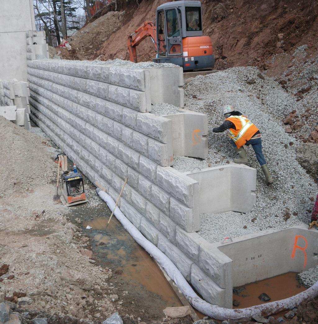
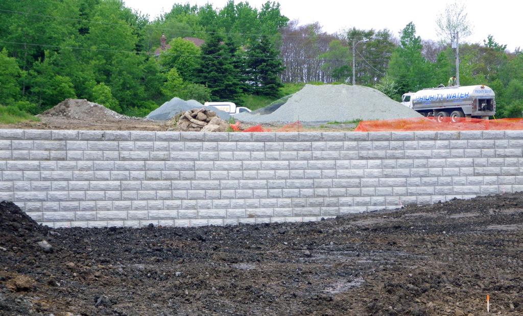
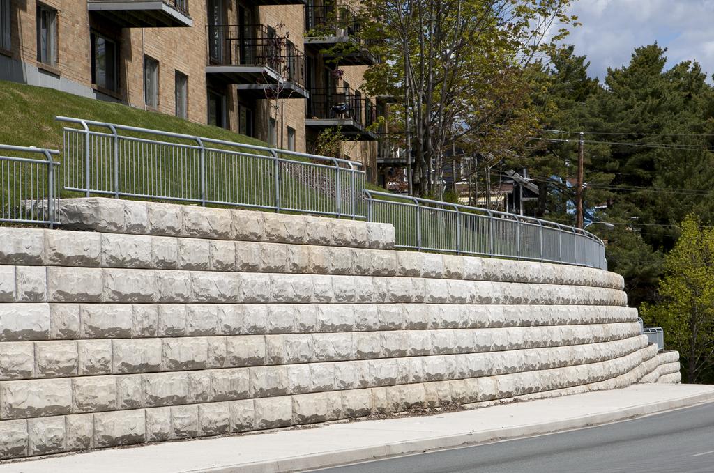
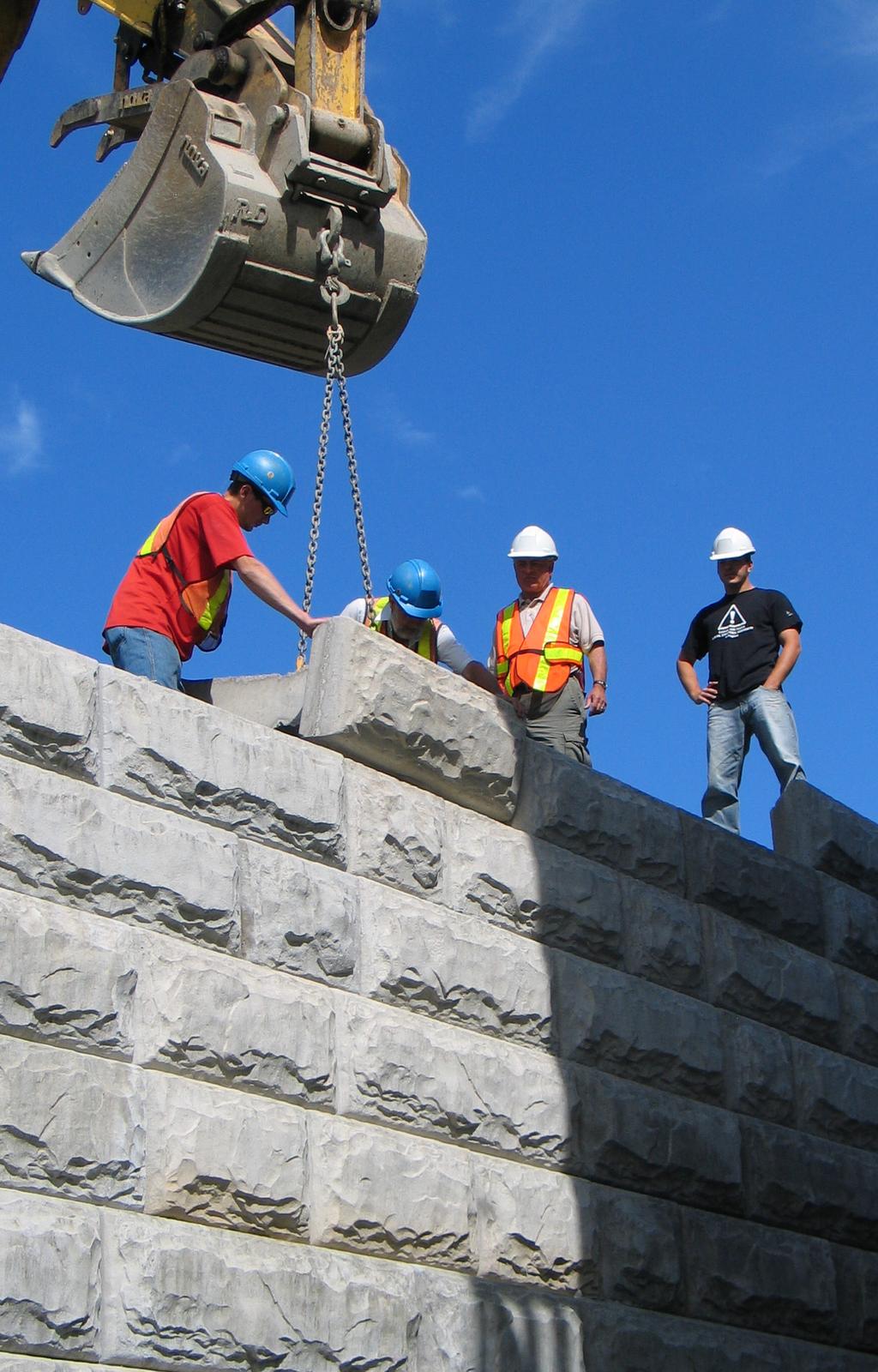
7 shawprecastsolutions.com STONE STRONG SYSTEMS STONE STRONG SYSTEMS Five years since Shaw Precast Solutions launched Stone Strong Systems, the retaining wall product that transformed the way both designers and property developers evaluate and choose retaining wall block. At 24 square feet per unit, the Stone Strong block is the largest precast block in the marketplace, twice as large as any competitive product. Placement of 24 square feet of wall area every time you set one block compared to many multiple sections of any other system, allowing you to build a substantial wall very quickly. The blocks tapered sides also make it easy to create both straight and winding designs, even convex, concave, and circular designs. Since 2007, sales have grown enormously. Now you can see Stone Strong everywhere you turn from highways to railroads to shoreline preservation projects. Recent installations include multi-unit apartment and condo sites, subdivision developments, and highway twinning projects. The big news this year is the launch of the new and blocks making the Stone Strong System even more competitive in the marketplace. Giving new meaning to the word huge, these new forms have double the depth at three feet high, eight feet long, and seven feet deep, the new blocks weigh more than 3,500 kilograms This means that enormous free-standing gravity walls can now be built. In the recent past, if a wall was higher than ten feet, expensive tie-backs or geo-grid systems (reinforcement with woven polyester or polypropylene mesh) would need to be used. These new large base blocks eliminate those expensive requirements. Contractors and customers are not only saving money, but the actual construction of these gravity walls is much faster. A wall recently completed in Lower Sackville that is 18 feet high and is totally a gravity installation. Due to the site property boundaries, Stone Strong was considered the product of choice. No other wall system could offer that height without encroaching on neighboring properties. Without the need for expensive tie-back systems, it allowed the owner and contractor to eliminate the need for over-excavation. Utilizing the new base block units, this gravity wall was constructed quickly and efficiently. As land steadily increases in price and developers are looking to get the most value out of every site, retaining walls continue to be a creative way to use all the available space and work around topographical challenges. Building bigger, higher, and longer walls can be part of the solution. If you require a wall that is economical, quick and easy to install, readily available, and comes with a supplier that can provide design-build expertise we suggest you consider Shaw Precast Solutions and the Stone Strong System for your next retaining wall application. SHAW PRECAST SOLUTIONS RETAINING WALLS > STONE STRONG SYSTEMS 7


8 STONE STRONG SYSTEMS REVISED November 12, SHAW PRECAST SOLUTIONS RETAINING WALLS > STONE STRONG SYSTEMS

9 STONE STRONG SYSTEMS shawprecastsolutions.com SHAW PRECAST SOLUTIONS RETAINING WALLS > STONE STRONG SYSTEMS 9
10 REVISEDNovember12,2012 STONE STRONG SYSTEMS 10 SHAW PRECAST SOLUTIONS RETAINING WALLS > STONE STRONG SYSTEMS
T-WALL.
 The T-WALL Retaining Wall System is a gravity structure constructed of individual precast T-WALL units. Each T-WALL unit consists of a front face panel and a stem, which extends back into and engages the
T-WALL Retaining Wall System
 CONSTRUCTION MANUAL T-WALL Retaining Wall System The T-WALL Solution... THE NEEL COMPANY 8328 Traford Lane Springfield, VA 22152 Phone 703-913-7858 Fax 703-913-7859 T-WALL Retaining Wall System CONSTRUCTION
CONSTRUCTION MANUAL. T-WALL Retaining Wall System FOR RAILROAD PROJECTS. The T-WALL Solution...
 T-WALL Retaining Wall System CONSTRUCTION MANUAL FOR RAILROAD PROJECTS T-WALL railroad units are 5.0' high x 7.5' wide. (stem lengths will vary) The T-WALL Solution... T-WALL Retaining Wall System CONSTRUCTION
Strengthened Soil Wall Construction Manual
 Strengthened Soil Wall Construction Manual This information has been prepared by Shaw Technologies, Inc. as an aid in constructing their Strengthened Soil Wall system. Final determination of the suitability
MagnumStone Specifications Gravity
 MagnumStone Specifications Gravity SPECIFICATION FOR MAGNUMSTONE GRAVITY MECHANICALLY STABILIZED EARTH SYSTEM PART 1: GENERAL.01Description The work consists of supplying and installing all aspects of
SPECIFICATIONS FOR PRECAST MODULAR BLOCK RETAINING WALL SYSTEM (revised 5/8/7)
") Page 1 of 7 STONE STRONG SYSTEMS SPECIFICATIONS FOR PRECAST MODULAR BLOCK RETAINING WALL SYSTEM (revised 5/8/7) PART 1: GENERAL 1.01 Description A. Work includes furnishing and installing precast modular
Page 1 of 7 STONE STRONG SYSTEMS SPECIFICATIONS FOR PRECAST MODULAR BLOCK RETAINING WALL SYSTEM (revised 5/8/7) PART 1: GENERAL 1.01 Description A. Work includes furnishing and installing precast modular
CONSTRUCTION MANUAL 2.5 x 5 UNITS
 CONSTRUCTION MANUAL 2.5 x 5 UNITS www.neelco.com 8328-D Traford Lane, Springfield, VA 22152 703 913 7858 T-WALL Retaining Wall System CONSTRUCTION Manual Contents Part I earthwork... 1 The Structure depends
SPECIFICATIONS FOR PRECAST MODULAR BLOCK RETAINING WALL SYSTEM (revised 9/17/18)
") Page 1 of 8 STONE STRONG SYSTEMS SPECIFICATIONS FOR PRECAST MODULAR BLOCK RETAINING WALL SYSTEM (revised ) PART 1: GENERAL 1.01 Description A. Work includes furnishing and installing precast modular blocks
Page 1 of 8 STONE STRONG SYSTEMS SPECIFICATIONS FOR PRECAST MODULAR BLOCK RETAINING WALL SYSTEM (revised ) PART 1: GENERAL 1.01 Description A. Work includes furnishing and installing precast modular blocks
SPECIFICATION FOR CORNERSTONE GEOGRID REINFORCED SEGMENTAL RETAINING WALL SYSTEM
 CornerStone Specifications Geogrid Reinforced SPECIFICATION FOR CORNERSTONE GEOGRID REINFORCED SEGMENTAL RETAINING WALL SYSTEM PART 1: GENERAL 1.01 Description The work consists of supplying and installing
UPRR INDUSTRIAL LEAD BRIDGE T-WALL RETAINING WALL SYSTEM 5.0 x 7.5 UNITS DESIGN UNIT 018 WORK PACKAGE 04
 UPRR INDUSTRIAL LEAD BRIDGE T-WALL RETAINING WALL SYSTEM 5.0 x 7.5 UNITS DESIGN UNIT 018 WORK PACKAGE 04 1. Description This work shall consist of the design, manufacture and construction of a T-WALL structure
SPECIFICATION FOR MAGNUMSTONE GEOGRID REINFORCED Mechanically Stabilized Earth (MSE) SYSTEM
 SYSTEM") MagnumStone Specifications Geogrid Reinforced SPECIFICATION FOR MAGNUMSTONE GEOGRID REINFORCED Mechanically Stabilized Earth (MSE) SYSTEM PART 1: GENERAL 1.01 Description The work consists of supplying
MagnumStone Specifications Geogrid Reinforced SPECIFICATION FOR MAGNUMSTONE GEOGRID REINFORCED Mechanically Stabilized Earth (MSE) SYSTEM PART 1: GENERAL 1.01 Description The work consists of supplying
Special Provision No. 599S22 March 2018 REQUIREMENTS FOR RETAINED SOIL SYSTEMS (RSS)
") RETAINED SOIL SYSTEM, TRUE ABUTMENT - Item No. RETAINED SOIL SYSTEM, FALSE ABUTMENT - Item No. RETAINED SOIL SYSTEM, WALL/SLOPE, HIGH PERFORMANCE - Item No. RETAINED SOIL SYSTEM, WALL/SLOPE, MEDIUM PERFORMANCE
RETAINED SOIL SYSTEM, TRUE ABUTMENT - Item No. RETAINED SOIL SYSTEM, FALSE ABUTMENT - Item No. RETAINED SOIL SYSTEM, WALL/SLOPE, HIGH PERFORMANCE - Item No. RETAINED SOIL SYSTEM, WALL/SLOPE, MEDIUM PERFORMANCE
DESIGNING AND CONSTRUCTION OF T-WALL RETAINING WALL SYSTEM
 Istanbul Bridge Conference August 11-13, 2014 Istanbul, Turkey DESIGNING AND CONSTRUCTION OF T-WALL RETAINING WALL SYSTEM T. C. NEEL and K.BOZKURT ABSTRACT This work shall consist of the design, manufacture
The Speed of Gravity. Gravity retaining walls built with Stone Strong System s Big Block Technology are the most efficient solution on the market.
 The Speed of Gravity. Gravity retaining walls built with Stone Strong System s Big Block Technology are the most efficient solution on the market. VERSATILITY. BLOCK SYSTEMS WITH WALL-TO-WALL ADAPTABILITY.
Uwall UNIVERSAL CONSTRUCTION MANUAL
 Uwall UNIVERSAL Retaining Wall System CONSTRUCTION MANUAL TM President s Letter CSI is a leader in its industry supplying precast infrastructure products throughout New England and beyond since 1972, developing
ENGINEERING DIRECTIVE
 Number: E-95-001 Date: 2/2/95 ENGINEERING DIRECTIVE Ross B. Dindio (Signature on Original) CHIEF ENGINEER The purpose of this engineering directive is to formally notify ALL Department engineering personnel
SECTION MECHANICALLY STABILIZED EARTH RETAINING WALLS
 SECTION 13100 MECHANICALLY STABILIZED EARTH RETAINING WALLS PART 1 -- GENERAL 1.01 THE REQUIREMENT A. Includes all labor, material, equipment, testing and submittals required to design and complete construction
Earth Retaining Structures and Systems Submittal Checklist. Part One: Materials and Material Properties
 Earth Retaining Structures and Systems Submittal Checklist Part One: Materials and Material Properties Provide a sample of the reinforcement material and material specifications describing the material
CHAPTER 13 - MECHANICALLY STABILIZED EARTH WALLS AND PATENTED EARTH RETAINING SYSTEMS
 CHAPTER 13 - MECHANICALLY STABILIZED EARTH WALLS AND PATENTED EARTH RETAINING SYSTEMS DS Temple 13.1 SCOPE This section covers the inspection of mechanically stabilized earth walls and other patented earth
SECTION LIMESTONE SEGMENTAL RETAINING WALLS
 (Specifier Notes: The purpose of this guide specification is to assist the specifier in correctly specifying segmental retaining walls and their installation. The specifier needs to edit this guide specification
204 - EXCAVATION AND BACKFILL FOR STRUCTURES SECTION 204 EXCAVATION AND BACKFILL FOR STRUCTURES. Granular Backfill (Wingwalls) (Set Price)
 (Set Price)") SECTION 204 EXCAVATION AND BACKFILL FOR STRUCTURES 204.1 DESCRIPTION Excavate for the structures as shown in the Contract Documents. Unless specified otherwise, backfill the completed structures to the
SECTION 204 EXCAVATION AND BACKFILL FOR STRUCTURES 204.1 DESCRIPTION Excavate for the structures as shown in the Contract Documents. Unless specified otherwise, backfill the completed structures to the
Reinforced Earth wall Construction Manual
 COVER PAGE CT-PE-W02 Rev: 5 Reinforced Earth wall Construction Manual Concrete Facing Reinforced Earth Malaysia Sdn Bhd 80-1, Jalan 8/62A Bandar Menjalara 52200 Kuala Lumpur Tel : 03-62746162, Fax : 03-62747212
Description. This work shall consist of furnishing materials and placement of modular block wall constructed in accordance with
 MODULAR CONCRETE BLOCK RETAINING WALL WITH GROUND REINFORCING The Standard Specifications are revised as follows: 732-R-310r 1of 11 Rev. 12-03-03 SECTION 105, AFTER LINE 48, INSERT AS FOLLOWS: When constructing
ODOT Design & Construction Requirements for MSE Walls
 ODOT Design & Construction Requirements for MSE Walls Peter Narsavage, P.E. Foundation Engineering Coordinator Ohio Department of Transportation Office of Structural Engineering 2006 Ohio Transportation
STANDARD SPECIFICATION FOR CRIBLOCK CONCRETE CRIBWALL
 STANDARD SPECIFICATION FOR CRIBLOCK CONCRETE CRIBWALL 1. SCOPE 2. DESIGN 3. MATERIALS 4. CONSTRUCTION 5. METHOD OF MEASUREMENT AND PAYMENT SCOPE This Specification sets out requirements for the design,
G R A V I T Y / G E O G R I D
 GRAVITY/GEOGRID MAGNUMSTONE Overview note: bolded terms are defined in our online glossary at www.cornerstonewallsolutions.com The MagnumStone retaining wall system was developed with the installer in
Michigan State University Construction Standards SEGMENTAL CONCRETE RETAINING WALLS PAGE SECTION SEGMENTAL CONCRETE RETAINING WALLS
 PAGE 323223-1 SECTION 323223 PART 1 - GENERAL 1.1 RELATED DOCUMENTS A. Drawings and general provisions of the Contract, including General and Supplementary Conditions and Division 01 Specification sections,
Section ( ) SPECIFICATION FOR SEGMENTAL CONCRETE UNIT RETAINING WALL
 SPECIFICATION FOR SEGMENTAL CONCRETE UNIT RETAINING WALL") Section 02834 (32 32 23) SPECIFICATION FOR SEGMENTAL CONCRETE UNIT RETAINING WALL PART 1: GENERAL 1.01 Description A. Work shall consist of furnishing and construction of a County Materials Retaining Wall
Section 02834 (32 32 23) SPECIFICATION FOR SEGMENTAL CONCRETE UNIT RETAINING WALL PART 1: GENERAL 1.01 Description A. Work shall consist of furnishing and construction of a County Materials Retaining Wall
Section ( ) MODULAR CONCRETE RETAINING WALL
 MODULAR CONCRETE RETAINING WALL") Section 02834 (32 32 23) MODULAR CONCRETE RETAINING WALL PART 1: GENERAL 1.01 Description A. Work shall consist of furnishing and construction of a KEYSTONE 133Elite Unit Retaining Wall System or equal
Section 02834 (32 32 23) MODULAR CONCRETE RETAINING WALL PART 1: GENERAL 1.01 Description A. Work shall consist of furnishing and construction of a KEYSTONE 133Elite Unit Retaining Wall System or equal
Redi Rock Specification and Installation Manual
 Redi Rock Specification and Installation Manual 1.0 General Scope This Specification covers the Design, Materials and Installation of Redi Rock modular block Retaining and Freestanding Wall systems as
Precast Panel Walls Wire Walls. Introducing the Grid-Strip TM Soil Reinforcement System. ail.ca. Saves time and money
 Precast Panel Walls Wire Walls Introducing the Grid-Strip TM Soil Reinforcement System ail.ca Saves time and money Save time. Save money. Specify a fast, economical Vist-A-Wall MSE Structural Wall System
ARMOR-BLOCK. Installation guide. Installation Manual: ARMOR-BLOCK Retaining Wall System. Cap Block. Exposed void for planting.
 ARMOR-BLOCK Installation guide Cap Block Exposed void for planting In situ soil Engineered backfill Compacted and prepared base Setback Lip Ph 0800 655 00 or visit www.csppacific.co.nz 19 February 08 /
SECTION MECHANICALLY STABILIZED EARTH 1.01 SUMMARY
 SECTION 028300 PART 1 GENERAL 1.01 SUMMARY A. Section includes Basis of Design Mechanically Stabilized Earth System: SierraScape Mechanically Stabilized Earth (MSE) retaining wall system having high density
SECTION SEGMENTAL CONCRETE UNIT MASONRY RETAINING WALL MAXIMUM HEIGHT OF 5-0 HIGH
 DIVISION 32 EXTERIOR IMPROVEMENTS SECTION 32 32 23.13 SEGMENTAL CONCRETE UNIT MASONRY RETAINING WALL MAXIMUM HEIGHT OF 5-0 HIGH PART 1: GENERAL 1.01 Scope of Standards A. This standard provides general
CHAPTER 11: WALLS.
 CHAPTER 11: WALLS MODULAR BLOCK WALL (DRY CAST) Rather than being pre-approved as systems, the components of Modular block walls (dry cast) are pre-approved separately. The approved MBW components are
Wall Modular Block Mechanically Stabilized Earth, Item S.
 Wall Modular Block Mechanically Stabilized Earth, Item 532.0300.S. A Description (1) This special provision describes designing, furnishing materials and erecting a permanent earth retention system in
SECTION CONCRETE SEGMENTAL RETAINING WALL SYSTEM
 SECTION 02832 CONCRETE SEGMENTAL RETAINING WALL SYSTEM PART 1.: GENERAL 1.01 WORK INCLUDED A. This section includes the following: The Specifications on furnishing the design, materials and labor required
LANDSCAPE RETAINING WALLS
 SUDAS Standard Specifications Division 9 - Site Work and Landscaping Section 9070 - Landscape Retaining Walls LANDSCAPE RETAINING WALLS PART - GENERAL.0 SECTION INCLUDES A. Modular Block Retaining Walls
Section ( ) KEYSTONE CONCRETE RETAINING WALL
 KEYSTONE CONCRETE RETAINING WALL") Section 02834 (32 32 23) KEYSTONE CONCRETE RETAINING WALL PART 1: GENERAL 1.01 Description A. Work shall consist of designing, furnishing and construction of a KEYSTONE Compac Unit Retaining Wall System
Section 02834 (32 32 23) KEYSTONE CONCRETE RETAINING WALL PART 1: GENERAL 1.01 Description A. Work shall consist of designing, furnishing and construction of a KEYSTONE Compac Unit Retaining Wall System
DESIGN CONSIDERATIONS FOR NSWS NATURAL STONE RETAINING AND FREE-STANDING WALL SYSTEMS
 DESIGN CONSIDERATIONS FOR NSWS NATURAL STONE RETAINING AND FREE-STANDING WALL SYSTEMS Natural Stone Wall Solutions, Inc (NSWS ) 2352 Main Street, Suite 103 Concord, MA 01742 (978) 461-1777 Concept and
MassBloc Permeable Instant Wall System
 PIPELINE SYSTEMS 131 004 www.rocla.com.au MassBloc Permeable Instant Wall System PIPELINE SYSTEMS MassBloc Retaining Wall Permanent Retaining Structures The Rocla MassBloc retaining wall system comprises
Installation Manual. ArchCast Bridge. 3-Sided Precast Concrete Bridge Structure
 ArchCast Bridge 3-Sided Precast Concrete Bridge Structure Installation Manual Salem Location: 749 West Commercial Ave. Salem, IL 62881 (618) 548-1190 countymaterials.com Email: info@countymaterials.com
ICBO Evaluation Service, Inc Workman Mill Road, Whittier, California
 ER-5435 Reissued May 1, 2002 ICBO Evaluation Service, Inc. 5360 Workman Mill Road, Whittier, California 90601 www.icboes.org Filing Category: DESIGN Masonry MESA RETAINING BLOCK WALL SYSTEM TENSAR EARTH
Bordeaux Walling. Product & Technical Information
 Product & Technical Information BORDEAUX WALLING Piece Piece Piece Block Block Block Block Pins No. per per Height Length Width Weight Layer Cube (kgs) 1 2 3 1 2 10 150 400/350 250 28 Yes 2 2 10 150 300/300
GABIONS AND REVET MATTRESSES
 GABIONS AND REVET MATTRESSES PART 1 - GENERAL 1.01 SECTION INCLUDES A. Gabions B. Revet Mattresses (Gabion Mattresses) 1.02 DESCRIPTION OF WORK A. Assembly and installation of gabions. B. Assembly and
Gravity Wall. A force to be reckoned with... Gravity (SRW) segmental retaining wall systems are structures
 segmental retaining wall systems are structures") A force to be reckoned with... Gravity (SRW) segmental retaining wall systems are structures lower in height that use the FrogStone unit weight combined with gravel core infill to resist earth pressures
A force to be reckoned with... Gravity (SRW) segmental retaining wall systems are structures lower in height that use the FrogStone unit weight combined with gravel core infill to resist earth pressures
204 - EXCAVATION AND BACKFILL FOR STRUCTURES SECTION 204 EXCAVATION AND BACKFILL FOR STRUCTURES
 SECTION 204 EXCAVATION AND BACKFILL FOR STRUCTURES 204.1 DESCRIPTION Excavate for the structures as shown in the Contract Documents. Unless specified otherwise, backfill the completed structures to the
GEOSYTHETIC SLOPE SPEC-V0704rev.doc STANDARD SPECIAL PROVISION FOR GEOSYNTHETIC REINFORCED SLOPE CONSTRUCTION
 GEOSYTHETIC SLOPE SPEC-V0704rev.doc STANDARD SPECIAL PROVISION FOR GEOSYNTHETIC REINFORCED SLOPE CONSTRUCTION I. DESCRIPTION - This work consists of furnishing the required materials and construction of
VERTI-BLOCK - DESIGN MANUAL
 Company Information General Information Verti-Block is the latest innovative forming system from Verti-Crete, LLC. Recognized worldwide for outstanding aesthetics and performance, Verti-Crete s proprietary
ICC-ES Evaluation Report Issued July 1, 2011 This report is subject to renewal in one year.
 ICC-ES Evaluation Report ESR-1959 Issued July 1, 2011 This report is subject to renewal in one year. www.icc-es.org (800) 423-6587 (562) 699-0543 A Subsidiary of the International Code Council DIVISION:
CONCRETE SEGMENTAL RETAINING WALLS
 32 32 23.13 CONCRETE SEGMENTAL RETAINING WALLS 1.00 GENERAL 1.01 DESCRIPTION A. The work shall consist of furnishing and installing concrete segmental retaining wall (CSRW) units to the lines, grades and
SECTION CONCRETE SEGMENTAL RETAINING WALL SYSTEM
 Anchor Vertica SECTION 02832 CONCRETE SEGMENTAL RETAINING WALL SYSTEM PART 1 - GENERAL 1.01 SECTION INCLUDES A. Retaining wall system constructed of concrete segmental retaining wall units. B. Geosynthetic
DIVISION 4100 SITEWORK
 DIVISION 4100 SITEWORK SECTION 4115 EARTHWORK PART 1 - GENERAL 1.01 SCOPE This section covers the grading and compaction of excavations, embankments, structural foundations, and planted areas. 1.02 REFERENCES
Steps And Stairs Installation Steps In Wall - Option 1 Steps In Front of Walls - Option 2 Steps In Wall; 10 (25cm) Tread - Option 3 Step Parallel to
 Tread - Option 3 Step Parallel to") Steps And Stairs Installation Steps In Wall - Option 1 Steps In Front of Walls - Option 2 Steps In Wall; 10 (25cm) Tread - Option 3 Step Parallel to Wall - Option 4 Steps and Stairs Q & A E CONSTRUCTION
Steps And Stairs Installation Steps In Wall - Option 1 Steps In Front of Walls - Option 2 Steps In Wall; 10 (25cm) Tread - Option 3 Step Parallel to Wall - Option 4 Steps and Stairs Q & A E CONSTRUCTION
B512 - GABIONS - OPSS 512
 B512 - - OPSS 512 512.1 GENERAL Gabions are contained rectangular units made of steel wire mesh and filled with stone. The double twisted wire mesh is galvanized and PVC (polyvinyl chloride) coated. Gabions
SAMPLE CONSTRUCTION AND MATERIAL SPECIFICATIONS FOR THE ULTRABLOCK GRAVITY WALL SYSTEM
 SAMPLE CONSTRUCTION AND MATERIAL SPECIFICATIONS FOR THE ULTRABLOCK GRAVITY WALL SYSTEM The following paragraphs provide general guidelines on developing construction and material specifications for specific
Best Practices for Design and Construction of MSE Walls
 Best Practices for Design and Construction Robert A. Gladstone, P.E. Executive Director Association for Mechanically Stabilized Earth Geotechnical Consultant Workshop Ohio Department of Transportation
SECTION ASPHALT CONCRETE
 SECTION 02740 ASPHALT CONCRETE PART 1. GENERAL 1.01 SECTION INCLUDES A. Work includes but is not limited to the following: 1.02 RELATED SECTIONS 1. Provide all material, labor, and equipment to prepare
DIVISION: EXTERIOR IMPROVEMENTS SECTION: SEGMENTAL RETAINING WALLS REPORT HOLDER: ANCHOR WALL SYSTEMS EVALUATION SUBJECT:
 0 Most Widely Accepted and Trusted ICC ES Evaluation Report ICC ES 000 (800) 423 6587 (562) 699 0543 www.icc es.org ESR 1959 Reissued 07/2018 This report is subject to renewal 07/2019. DIVISION: 32 00
Earth Retaining System
 Hashemite University Department of Civil Engineering Foundation Engineering Dr. Omar Al-Hattamleh Earth Retaining System Earth slopes and earth retaining structures Used to maintain two different ground
Construction Procedures
 Construction Procedures 2014 Rev. 1.6 1 Introduction This manual presents the methods and procedures necessary for the proper erection of a LOCK+LOAD retaining wall. problems later during the service life
Design & Detail Installation Manual. LongSpan Bridge and Culvert Construction System
 Design & Detail Installation Manual LongSpan Bridge and Culvert Construction System Table of Contents 1.0 Long Span Installation... 2 2.0 Long Span Conceptual Details... 3 3.0 Footing Options... 6 4.0
Bolt-A-Bin. We Support You. We Support You.
 www.ail.ca Bolt-A-Bin We Support You. We Support You. Our Commitment Atlantic Industries Limited (AIL) has built a solid reputation by providing professional support and innovative, high quality corrugated
MODULAR CONCRETE RETAINING WALL
 MODULAR CONCRETE RETAINING WALL PART 1: GENERAL 1.01 Description A. Work shall consist of furnishing and construction of a KEYSTONE Retaining Wall System or equal in accordance with these specifications
Save time. Save money. Specify a fast, economical Vist-A-Wall MSE. fast and easy to install. They adapt well to curves, angles and
 bigrbridge.com Save time. Save money. Specify a fast, economical Vist-A-Wall MSE Structural Wall System for your next engineered embankment project. These historically-proven, cost-effective systems have
CONCRETE SEGMENTAL RETAINING WALL SYSTEM
 CONCRETE SEGMENTAL RETAINING WALL SYSTEM PART 1: GENERAL SPECIFICATIONS 1.01 Work Included A. Work shall consist of furnishing and constructing a Rockwood Classic 8, Classic 6 and Legend unit segmental
Garden WallScape Installation Guide
 By CornerStone Wall Solutions Inc. Garden WallScape Installation Guide GRAVITY/DETAILS The perfect balance... between design and nature Garden WallScape Overview note: bolded terms are defined in our online
Steps And Stairs Installation Option 1 - Steps In Wall Option 2 - Steps With Plant Space Option 3 - Steps In Front of Walls Option 4 - Steps Along
 Steps And Stairs Installation Option 1 - Steps In Wall Option 2 - Steps With Plant Space Option 3 - Steps In Front of Walls Option 4 - Steps Along Wall Face Option 5 - Steps In Wall; 10 (25cm) Tread Option
NOVEMBER 2016 MAGNUMSTONE. retaining walls installation manual
 NOVEMBER 2016 MAGNUMSTONE retaining walls installation manual AUSTRAL MASONRY CONTENTS Magnumstone Installation Guide 04 Overview 07 Unit Specifications 08 Installation 08 Gravity MagnumStone Wall 16 Geogrid
Horizontal Ellipse. Contact LSBC for additional sizes. Buried Ellipse for Pedestrian Traffic. Elliptical Stream Crossing
 Horizontal Ellipse By eliminating the need for concrete footings this shape can often provide the lowest overall installed cost of any long span structure. If a natural stream bottom is desired the invert
Right look. Right strength. Right size.
 www.vertiblock.com.au Verti-Block Retaining Walls Hollow, interlocking blocks Sized for residential and commercial use Right look. Right strength. Right size. Innovative engineering for unparalleled strength
Design and Installation Guidelines for Retaining Walls. 1 P age. Geo Products, LLC 8615 Golden Spike Lane Houston, TX Phone:
 Design and Installation Guidelines for Retaining Walls 1 P age Geo Products, LLC 8615 Golden Spike Lane Houston, TX 77086 Phone: 281.820.5493 2011 Geo Products, Fax: 281.820.5499 LLC www.geoproducts.org
Geoguide 6 The New Guide to Reinforced Fill Structure and Slope Design in Hong Kong
 Geoguide 6 The New Guide to Reinforced Fill Structure and Slope Design in Hong Kong Geotechnical Engineering Office Civil Engineering Department The Government of the Hong Kong Special Administrative Region
Michael R. Lockwood Construction Management National Museum of the Marine Corps Quantico, VA
 Soil Retention System Design and Analysis Executive Summary The National Museum of the Marine Corps has a unique design element that portrays an image that the building is built underground. In order to
A. Modular Unit - A concrete wall interlocking element, machine made from portland cement, water and aggregates.
 Section 02832 - Page 1 PART 1 - GENERAL 1.1 SUMMARY 1.2 DEFINITIONS 1.3 SUBMITTALS 1.4 JOB MOCK-UP A. This section includes furnishing and installation of modular interlocking concrete masonry units bearing
Section (02830) MODULAR CONCRETE RETAINING WALL
 MODULAR CONCRETE RETAINING WALL") Section 323223 (02830) MODULAR CONCRETE RETAINING WALL PART 1: GENERAL 1.01 Description A. Work shall consist of furnishing and constructing a VERDURA Retaining Wall System (or approved equal) in accordance
Section 323223 (02830) MODULAR CONCRETE RETAINING WALL PART 1: GENERAL 1.01 Description A. Work shall consist of furnishing and constructing a VERDURA Retaining Wall System (or approved equal) in accordance
Wmega Retaining Wall Specification
 Wmega Retaining Wall Specification 1. General 1.01 Description A. This work shall consist of furnishing and installing an Ωmega Segmental Retaining Wall System in accordance with these specifications and
MagnumStone. Product Brochure
 MagnumStone Product Brochure MagnumStone Innovative design... easy on the environment While still sharing the same hollow core that our dry cast products have, our MagnumStone product is perfect for DOT
TERRASTOP SYSTEM 2 RETAINING WALLS. Section Page 1 PART 1 - GENERAL 1.1 SUMMARY
 Section 02832 - Page 1 PART 1 - GENERAL 1.1 SUMMARY 1.2 DEFINITIONS 1.3 SUBMITTALS 1.4 JOB MOCK-UP A. This section includes furnishing and installation of modular interlocking concrete masonry units bearing
SECTION EXCAVATION AND EMBANKMENT. B. Subbase Grading A samples for gradation analysis.
 PART 1 GENERAL 1.1 DESCRIPTION A. The WORK under this Section includes providing all labor, materials, tools and equipment necessary for excavation and embankment construction to the lines, grades and
Verti-Block Design Manual Section 1 - Gravity Wall (Standard)
") Canadian Version Release 2.0 Verti-Block Design Manual Section 1 - Gravity Wall (Standard) Native gravelly soil, edge of excavation Native soil compacted in place as each course is set Geotextile Filter
Canadian Version Release 2.0 Verti-Block Design Manual Section 1 - Gravity Wall (Standard) Native gravelly soil, edge of excavation Native soil compacted in place as each course is set Geotextile Filter
PISA. Retaining Wall System. The choice of professional contractors
 PISA Retaining Wall System The choice of professional contractors PRODUCT CODE DESCRIPTION & DIMENSIONS (H x W x D) ~ WEIGHT PER UNIT No./M² No./ Lin M² UNITS PER PALLET 5501 Light Vertical Straight Unit
SECTION SEGMENTAL RETAINING WALL
 Note: This guide specification should not be included entirely as-is. Specification writers must edit areas in red which may or may not be relevant to a specific project or where mutually exclusive choices
NOVEMBER 2016 GRANDWALL. retaining walls installation guide
 NOVEMBER 2016 GRANDWALL retaining walls installation guide RETAINING WALL INSTALLATION GUIDE RETAINING WALL information Austral Masonry Grandwall retaining wall blocks are an ideal choice for retaining
Anchorplex retaining wall construction guide
 Anchorplex retaining wall construction guide Building Anchorplex Retaining Wall Systems Table of Contents and Introduction table of contents ow to Use This Guide......................... 2 About the Anchorplex
AUGUST 2017 HASTINGS. retaining walls installation guide
 AUGUST 2017 HASTINGS retaining walls installation guide RETAINING WALL INSTALLATION GUIDE RETAINING WALL information Austral Masonry retaining wall blocks are an ideal choice for retaining walls in gardens,
DIVISION: EXTERIOR IMPROVEMENTS SECTION: RETAINING WALLS SECTION: SEGMENTAL RETAINING WALLS REPORT HOLDER:
 0 Most Widely Accepted and Trusted ICC-ES Evaluation Report ICC-ES 000 (800) 423-6587 (562) 699-0543 www.icc-es.org ESR-1784 Issued 02/2018 This report is subject to renewal 02/2019. DIVISION: 32 00 00
DE-SPAN Design Guideline. Manufactured 100% indoors. Under 100% controlled conditions.
 DE-SPAN Design Guideline Manufactured 100% indoors. Under 100% controlled conditions. DE-SPAN DE-SPAN is a rigid-portal framed bridge system. Modules are designed with a horizontal deck to support soil
CAPRICORN MUNICIPAL DEVELOPMENT GUIDELINES PRECAST BOX CULVERTS CONSTRUCTION SPECIFICATION
 CAPRICORN MUNICIPAL DEVELOPMENT GUIDELINES C222 CONSTRUCTION SPECIFICATION CAPRICORN MUNICIPAL DEVELOPMENT GUIDELINES C222 ISSUE: NO:3 July 2018 TABLE OF CONTENTS CLAUSE CONTENTS PAGE GENERAL... 2 C222.01
STORMCAPTURE. Installation Manual
 STORMCAPTURE Installation Manual Introduction Site Preparation Delivery & Installation LinkSlabs Backfill Introduction StormCapture (shown in Figure 1) is a total stormwater management system. The highly-configurable
1.02 RELATED WORK: Refer to the following sections for related work: Section 4000-Concrete Materials and Methods
 SECTION 2000- EARTHWORK PART 1- GENERAL 1.01 SCOPE: This Section covers excavation, fill, and compaction of earth and rock for roadway, embankments, structural foundations, and planted areas. Topics include
ROAD COMMISSION FOR OAKLAND COUNTY. SPECIAL PROVISION FOR GABION WALL RCOC/DESIGN: AB Page 1 of 8 RCOC12SP706F 10/28/2013
 ROAD COMMISSION FOR OAKLAND COUNTY SPECIAL PROVISION FOR GABION WALL RCOC/DESIGN: AB Page 1 of 8 RCOC12SP706F a. Description This work shall be done in accordance with Section 205 and 206 of the 2012 Michigan
CONSTRUCTION MANUAL 5-0 x 7-6 UNITS
 CONSTRUCTION MANUAL 5-0 x 7-6 UNITS www.neelco.com 8328-D Traford Lane, Springfield, VA 22152 703 913 7858 NOTE TO THE READER This manual has been prepared as a guide to building T-WALL Retaining Wall
Monumental Blok. Pallet Overview. Compatible caps. Notes. code 3521 (a) 3522 (b) 3523 (c) texture Chiseled. Specifications per pallet.
 3522 (b) 3523 (c) texture Chiseled. Specifications per pallet.") Monumental Blok code 3521 (a) 3522 (b) 3523 (c) texture Chiseled Pallet Overview (see below) HALF Specifications per pallet Imperial Metric Cubing 13.80 ft 2 /pal. (1.28 m 2 )/pal. 1.73 ft 2 /unit (0.16
Monumental Blok code 3521 (a) 3522 (b) 3523 (c) texture Chiseled Pallet Overview (see below) HALF Specifications per pallet Imperial Metric Cubing 13.80 ft 2 /pal. (1.28 m 2 )/pal. 1.73 ft 2 /unit (0.16
SECTION SPECIFICATION FOR MECHANICALLY STABILIZED EARTH TWO STAGE WALL SYSTEM
 SECTION 02830 SPECIFICATION FOR MECHANICALLY STABILIZED EARTH TWO STAGE WALL SYSTEM ## THIS SECTION IS WRITTEN IN CSI 3-PART FORMAT AND IN CSI PAGE FORMAT. NOTES TO THE SPECIFIER, SUCH AS THIS, ARE INDICATED
Construction Procedures
 Construction Procedures 2016 Rev. 1.7 1 Contents Introduction...... 3 Base Row Layout........ 4 Drainage and Backfill..... 6 Compaction... 7 Subsequent Rows... 8 In Pictures.... 10 Variations.. 11 Step
Notes for Erection of Evergreen Maxi Wall Retaining Walls
 Notes for Erection of Evergreen Maxi Wall Retaining Walls 1. Evergreen Maxi General Notes A. Project drawings - See project drawings for complete layout of utilities, railroad tracks, existing and proposed
Section (1997 Section 02795) PERMEABLE, FLEXIBLE and PLANTABLE CONCRETE EROSION CONTROL SYSTEM
 PERMEABLE, FLEXIBLE and PLANTABLE CONCRETE EROSION CONTROL SYSTEM") PART 1: Section 32 12 43 (1997 Section 02795) PERMEABLE, FLEXIBLE and PLANTABLE CONCRETE EROSION CONTROL SYSTEM GENERAL 1.01 Description A. Work shall consist of furnishing all material, labor, services
PART 1: Section 32 12 43 (1997 Section 02795) PERMEABLE, FLEXIBLE and PLANTABLE CONCRETE EROSION CONTROL SYSTEM GENERAL 1.01 Description A. Work shall consist of furnishing all material, labor, services
SEGMENTAL BLOCK RETAINING WALLS. Comply with Division 1 - General Provisions and Covenants, as well as the following:
 SEGMENTAL BLOCK RETAINING WALLS PART 1 - GENERAL 1.01 SECTION INCLUDES Segmental Block Retaining Walls 1.02 DESCRIPTION OF WORK Constructing segmental block retaining walls. 1.03 SUBMITTALS Comply with
SECTION 19 - TRENCH EXCAVATION, BEDDING AND BACKFILL TABLE OF CONTENTS
 SECTION 19 - TRENCH EXCAVATION, BEDDING AND BACKFILL TABLE OF CONTENTS Section Page 19-1 TRENCH EXCAVATION... 19.1 19-1.01 Exploratory Excavation... 19.1 19-1.02 Trench Width... 19.1 19-1.02.A Storm Drain