MECHANICAL BEHAVIOUR AND DURABILITY PERFORMANCE OF CONCRETE CONTAINING RECYCLED CONCRETE AGGREGATE
|
|
|
- Maude Ward
- 6 years ago
- Views:
Transcription

1 MECHANICAL BEHAVIOUR AND DURABILITY PERFORMANCE OF CONCRETE CONTAINING RECYCLED CONCRETE AGGREGATE SUVASH CHANDRA PAUL THESIS PRESENTED FOR THE DEGREE OF MASTER OF SCIENCE AT THE DEPARTMENT OF CIVIL ENGINEERING OF THE UNIVERSITY OF STELLENBOSCH SUPERVISOR: PROF G.P.A.G van ZIJL DECEMBER: 2011
2 DECLARATION I, the undersigned, hereby declare that the work contained in this thesis report is my own original work and that I have not previously in its entirety or in part submitted it at any university for a degree. Signature: Date: Copyright 2011 Stellenbosch University All rights reserved
3 ABSTRACT A major challenge for our society is the protection of the environment. Some of the important issues are the reduction in the consumption of energy and natural raw materials, as well as the increase in consumption of waste materials. At present these topics are getting considerable attention as part of sustainable development programs. The use of recycled concrete aggregates (RCA) from construction and demolition waste (C&DW) in construction, as alternative to virgin (natural) aggregates, has strong potential. The use of RCA preserves natural resources and reduces the space required for the disposal of RCA in landfill. It is estimated that 16 thousand million (billion) tons of concrete (and 25 billion tons of aggregate) were used in Of the 2-3 billion tons of C&DW which are produced worldwide every year, South Africa contributes 5-8 million tons. This amount is increasing rapidly every year. Significant amounts of demolished concrete find their way to landfill sites. A solution for excess waste production would be the utilization of RCA together with an improvement in the final quality of RCA. It might be an important breakthrough for our society in our attempt towards sustainable development. Worldwide, infrastructure has developed a great deal since the beginning of the twentieth century. Much of the core infrastructure, including roads, bridges, water systems, and sewers, was put in place during the first half of that century. Aggregates used as construction materials, as for instance in road pavements, or as an ingredient of concrete, are important components of infrastructure. Urbanization involves reduction of natural aggregate (NA) resources, but environmental concern and the rising cost of NA is the reason that recycled materials from different sources (like roads, buildings) are being used more and more with NA in new construction work. Environmental awareness is increasing in every country for many reasons and sustainable development is demanded of all industries, including the building and construction industries. By nature, construction is not environmentally friendly, and sometimes it also changes the behavior of nature in many ways. Recycling is one of the most important ways to minimize the waste that comes from different sources, thereby avoiding repetition of, and additional environmentally hazardous practices. It may create new wealth by diminished transport and production costs and sparing of landfill site space and cost. It has the potential to extend the life of natural resources by adding a source of material, thereby reducing environmental interference and impacting on nearby construction sites, all of which improve sustainability of our natural resources. Much research on the uses of RCA has been performed during the last few decades. In fact, most of them showed that the strength class of recycled aggregate concrete (RAC) is adequate for use as structural concrete although volume changes in and durability performance of RAC in comparison with natural aggregate concrete (NAC) are still being debated and researched. Some researchers found that the durability of concrete produced with RCA is inferior, but others have found it to be sufficient for use in structural concrete. The fact that an insufficient number of i
4 studies have been carried out on the durability aspects, has limited the use of RCA as material for road construction. The aim of this study is to determine the suitability of using the RCA in structural concrete based on its strength, stiffness, dimensional stability and durability. Three types of RCA designated RCA1, RCA2 and RCA3 in this study, were taken from three different sources. These materials were tested to establish their mechanical characteristics for use as aggregates in concrete. In the experimental program RCA was used at replacement percentages of 0%, 30% and 100% to (partially) replace NA in order to study its suitability as aggregate in concrete, and to what level of NA replacement its behavior is satisfactory for structural application. A single compressive strength class was studied, due to the limited time. By performing tests of compressive strength, Young s modulus, creep, shrinkage, and durability performance, it has been found that selected types of RCA show a real possibility for use as aggregate in concrete. When concrete with a RCA replacement of 100% was compared with NAC100% there was a small decline in strength, but when concrete with a RCA replacement of 30% was compared with NAC100% the results showed almost equal strength. A slight reduction in durability performance was found for RAC30% compared with NAC100%, but similar dimensional stability performance in terms of specific creep and drying shrinkage was measured for RAC30% and NAC100%. Based on detailed experimental results obtained from this thesis project, a number of recommendations have therefore been made for RCA characteristics that will be used in concrete mixes also taking into account the quality of RCA. Some suggestions are proposed based on the mechanical properties and durability of the concrete. In the final conclusions, future studies on RCA properties are suggested, which would help us in increasing our knowledge in the application of RCA, and which may lead to the optimal production of structural concrete in a sustainable way. In general the use of RCA in concrete is feasible and good quality RCA at 30% replacement of NA may be suitable for any kind of structural concrete. ii
5 SAMEVATTING n Groot uitdaging vir ons samelewing is die beskerming van die omgewing. Van die belangrike sake is die vermindering in die verbruik van energie en van natuurlike, onverwerkte materiale asook die groter verbruik van afvalmateriaal. Hierdie onderwerpe kry tans aanienlike aandag as deel van volhoubare ontwikkelingsprogramme. Die gebruik van betonaggregate, herwin vanaf konstruksie-en slopingsafval, en gebruik in konstruksie as alternatief vir ongebruikte natuurlike aggregate, het goeie potensiaal. Die gebruik van herwonne aggregaat beskerm natuurlike hulpbronne en verminder die oppervlakte en volume wat nodig is vir die weggooi daarvan op stortingsterreine. Dit is beraam dat 16 duisend miljoen (biljoen) ton beton (en ongeveer 25 biljoen ton aggregaat) gedurende 2010 gebruik is. Van die 2-3 biljoen ton konstruksie-en slopingsafval wat jaarliks wêreldwyd gegenereer word, dra Suid Afrika 5-8 miljoen ton by. Hierdie hoeveelheid word elke jaar vinnig meer. Beduidende hoeveelhede gesloopte beton beland elke jaar op stortingsterreine. n Oplossing vir die probleem van te veel atval generering sou wees die gebruik daarvan as herwonne beton-aggregaat, sou saamval met n verbetering in die uiteindelike kwaliteit van herwonne aggregaat beton. Dit kan dalk n belangrike deurbraak wees vir ons samelewing in ons strewe na volhoubare ontwikkeling. Infrastruktuur het wêreldwyd baie ontwikkel sedert die begin van die twintigste eeu. Baie van die kerninfrastruktuur insluitende paaie, brue, waterstelsels en riole is gebou tydens die eerste helfte van daardie eeu. Aggregaat gebruik as konstruksiemateriaal, byvoorbeeld in padplaveisels of as n bestanddeel van beton, is n belangrike deel van infrastruktuur. Verstedeliking veroorsaak vermindering van natuurlike aggregaat hulpbronne maar besorgdheid oor die omgewing en die stygende koste van nataurlike aggregaat veroorsaak dat herwonne materiale vanaf verskillende bronne (soos paaie en geboue) meer en meer aanvullend tot natuurlike aggregaat in nuwe konstruksiewerke gebruik word. Omgewingsbewustheid is om baie redes aan die toeneem in elke land en volhoubare ontwikkeling word vereis van alle industrieë. Herwinning is een van die hoofmaniere om afval vanaf verskillende bronne tot n minimum te beperk. Dit skep nuwe rykdom, verminder vervoeren vervaardigingskoste en benut afval wat anders op stortingsterreine verlore sou gegaan het. Dit het die potensiaal om die lewensduur van natuurlike hulpbronne te verleng deur n materiaalbron by te voeg, deur inmenging in die omgewing te verminder, wat almal bevorderlik is om volhoubare benutting van ons hulpbronne te verbeter. Baie navorsing is gedurende die laaste paar dekades gedoen aangaande die gebruik van herwonne aggregaat. Die meeste van die navorsing het inderdaad getoon dat die sterkte van beton met herwonne aggregaat genoegsaam is vir gebruik as struktuurbeton alhoewel daar wel debatte gevoer word oor die volumeveranderings en duursaamheid prestasie van herwonne aggregaat beton vergeleke met dié van natuurlike aggregaat beton. Sommige navorsers het bevind dat die duursaamheid van beton wat met herwonne aggregaat gemaak is, minderwaardig iii
6 is maar andere het bevind dat dit voldoen aan die vereistes van struktuurbeton. Slegs die feit dat daar onvoldoende toetse rakende duursaamheid gedoen is, het die gebruik van herwonne beton aggregaat beperk tot padboumateriaal. Die doel van hierdie navorsing is om te bepaal wat die geskiktheid van herwonne betonaggregaat is vir gebruik in struktuurbeton, gegrond op sterkte en duursaamheid. Drie soorte herwonne betonaggregaat wat in hierdie studie as RCA1, RCA2 and RCA3 aangedui word, is elk vanaf n ander bron geneem. Hierdie materiale is getoets om hulle meganiese kenmerke vas te stel vir gebruik as aggregaat in beton. In die eksperimentele program is 0%, 30% en 100% herwonne betonaggregaat gebruik om natuurlike aggregaat gedeeltelik be vervang om sodoende die geskiktheid as betonaggregaat te bestudeer. Deur toetse uit te voer op n beperkte sterkte-klas beton, soos toetse vir die bepaling van druksterkte, Young s modulus, kruip, krimp en duursaamheid, is daar bevind dat sekere soorte herwonne betonaggregaat heel moontlik gebruik kan word in struktuurbeton. Toe beton met 100% herwonne betonaggregaat vergelyk is met beton met 100% natuurlike aggregaat, is bevind dat daar n klein vermindering in sterkte was, maar waar beton met 30% herwonne betonaggregaat vergelyk is met beton met 100% natuurlike aggregaat, het die resultate byna dieselfde sterkte getoon. Dus op grond van gedetaileerde eksperimentele resultate is n aantal aanbevelings gemaak vir kenmerke van herwonne betonaggregaat wat in betonmengsels gebruik sal word met inagneming van die gehalte van herwonne betonaggregaat. Die resultate vir beton met 30% en 100% herwonne betonaggregaat word vergelyk met beton wat slegs natuurlike aggregaat bevat. Sekere voorstelle gegrond op meganiese eienskappe en duursaamheid van die beton word gemaak, asook aanbevelings vir toekomstige studies van herwonne betonaggregaat wat ons sal help om ons kennis vir die toepassing van herwonne betonaggregaat uit te brei. iv
7 ACKNOWLEDGEMENTS I would like to give the most sincere appreciation and kind gratitude to the following people for their assistance: Professor Gideon P.A.G. van Zijl, my supervisor, for his kind supervision, guidance, support and insight throughout this important study. The valuable advice and support of Professor Mark Alexander, Dr Hans Beushausen from University of Cape Town and Professor Elsabe Kearsley from University of Pretoria is gratefully acknowledged. I express sincere thanks to the staff of the laboratory and workshop of the Civil Engineering Department, University of Stellenbosch. Gratefully acknowledge to the University of Pretoria for providing five creep frames during this thesis period and the University of Cape Town for their time and effort in assisting with the durability index test in their concrete laboratory. I also would like to express thanks to my classmates and friends for their helping attitude, appreciation and encouragement during this thesis period. I am grateful to my family especially my mother, brother Suman and sister Dipa for your encouragement during my stay abroad. The financial assistance of the South African Industry and the Technology and Human Resources for Industry Programme (THRIP) of the South African Ministry of Trade and Industry towards this dissertation is hereby acknowledged. The author would like to dedicate the whole work to his beloved parent. v
8 THESIS LAYOUT CHAPTER-1: INTRODUCTION This chapter briefly introduces the reader to the topic of the behaviour and performance of recycled concrete aggregate and gives a description of RCA and discusses its advantages and disadvantages. This chapter also serves to state the research problems and its aim and sets the stage for the overall research presented in the report. CHAPTER-2: LITERATURE REVIEW AND BACKGROUND OF RECYCLED CONCRETE AGGREGATE In this chapter a historic overview of concrete and the use of RCA are presented to the reader. This is then followed by the background of waste production in the world, of RCA as used in civil and structural applications from a historical perspective as well as the method of recycling. The chapter concludes with an overview and examples of the economic factors and benefits realized through the use of Light Aggregate Concrete (LAC) in civil and structural applications. The economic overview also throws light on the key aspects of RCA that benefit the overall concrete composition in structural applications. It also provides a detailed review of the various RCA compositions used during the initial stages of RCA s use in the construction industry. CHAPTER-3: RECYCLING BUSINESS This chapter presents a detailed overview of the recycling business, of the equipment required for recycling, of South African construction waste pattern and of steps required to introduce recycling into South Africa. CHAPTER 4: EXPERIMENTAL PROGRAM In this chapter a detailed overview of the different materials studied in this project, of the physical properties of materials, of the preparation of materials and of casting concrete specimens, is described. Besides these the test setup for concrete specimens in accordance with different guidelines for the four steps of this thesis work is described. CHAPTER-5: CONCRETE TEST RESULTS AND DISCUSSION This chapter presents a critical analysis of the properties of RCA and the various combinations of recycled aggregate that are used in different categories of construction. The research throws light on the various compositions of recycled aggregate and their distinct features that help achieve the desired benefits in a structural application. A critical overview is given on the regulations vi
9 pertaining to RCA followed by the composition analysis based on the materials that are available locally in a given geographical location. CHAPTER-6: DURABILITY PERFORMANCE OF NAC & RAC This chapter of thesis covers the durability performance of 30% replacement of NA with RCA as compared with 100% NAC. Three tests, namely oxygen permeability, water sorptivity and chloride conductivity have been performed and the results are presented graphically. Test results on creep and shrinkage are also reported on. CHAPTER-7: CONCLUSION AND RECOMMENDATION This chapter reviews the research objectives and states the related conclusions. The overall performances of RCA are compared with conventional concrete and recommendations are made for further work. vii
10 NOTATIONS E: Modulus of elasticity of concrete E k : Characteristic E-modulus of concrete σ: Compressive strength of concrete ϵ: Strain of concrete ϵ co : Strain at peak strength ϵ u : Ultimate strain ϵ c : Creep strain : Mean compressive strength of concrete : Splitting tensile strength of concrete : Flexural strength of concrete : Cylinder compressive strength concrete : Cube compressive strength concrete, : Characteristic cylinder compressive strength concrete, : Characteristic cube compressive strength concrete : Probability density function µ: Mean value of strength k: Coefficient of permeability C c : Specific creep z: Slope of the linear regression line d: Average thickness of the specimen s: Water sorptivity of the specimen n: Porosity of specimen F: Slope of the best fit line A c : Cross sectional area Ф (t) : Creep coefficient Ф o : Notational creep coefficient M sv : Vacuum saturated mass of specimen M so : Initial mass of specimen M wti : Mass gained of specimen at any time ω: Molecular mass of oxygen ρ w : Density of water viii
11 ABBREVIATIONS AASHTO: American association of State Highway and Transport Officials ACPA: American Concrete Pavement Association ASR: Alkali silica reaction ASTM: American Standard Testing materials Ave : Average value CCRCA: Concrete Containing Recycled Concrete Aggregate CDF: Cumulative distribution function C&DW : Construction & Demolished Waste CoV: Coefficient of variation ECCO: Environmental Council of Concrete Organization. FACT: Fine aggregate crushing value. GGCS: Ground Granulated Corex Slag GHG: Green House Gas. HRM: Heating and Rubbing Method ITZ: Interfacial transition zone LAC: Light Aggregate Concrete LVDTs: Linear variable differential transformers MOC: Ministry of Construction MR: Modulus of Rupture NA: Natural aggregate NAC: Normal aggregate concrete NFESC: Naval Facilities Engineering Service Centre NRMCA: American National Ready Mix Concrete Association OPC: Ordinary Portland Cement OPI: Oxygen permeability index PCC: Portland Cement Concrete PDF: Probability density function RA: Recycled aggregate RAC: Recycled aggregate concrete RCA: Recycled concrete aggregate RH: Relative Humidity SSD: Saturated surface dry USGS: United States Geological Survey WSDOT: Washington State Department of Transportation W/C: Water cement ratio ix
12 TABLE OF CONTENTS ABSTRACT... i-iv ACKNOWLEDGEMENT...v THESIS LAYOUT. vi-vii NOTATIONS.....viii ABBREVIATIONS..ix CHAPTER - 1: INTRODUCTION 1.1. Concrete usage and waste Description of NA and RCA Technical benefit of RCA Economical, environmental and social benefits of recycling Recycling saves energy Recycling creates extra job opportunities Recycling saves natural resources Economic benefit Recycling saves space for waste disposal Sustainability Good wide market Disadvantages of recycling Lack of codes, specifications, standards and guidelines Air pollution Water pollution Poor image Lack of experience Low quality Variations in quality Application of RCA Embankment fill materials Paving blocks Road construction Bank protection Problem statement Properties of concrete made with RCA The need for C&DW minimization Aim of research Brief conclusion...12 x
13 CHAPTER 2: LITERATURE REVIEW AND BACKGROUND OF RECYCLED CONCRETE AGGREGATE 2.1. Introduction Literature review of RCA Physical performance of RCA Mechanical performance including stiffness and flexural strength of concrete containing RCA RCA percentage in NA Shrinkage and creep behaviour of concrete containing RCA Durability of RAC Interfacial transition zone in RAC Research problem and background Building materials waste in the world Volume estimate of waste and reuse in different country Some international projects using RCA Netherland United Kingdom Germany Norway Properties of aggregate made from C&D waste Size distribution Absorption Abrasion resistance Specification for RCA Requirements in Dutch regulation for use in concrete Requirements in Japanese to use in concrete Requirements in Hong Kong to use in concrete RCA specifications in different codes Standard test for impurities Comparison between NA and RCA physical and mechanical properties Brief conclusion...37 CHAPTER 3: RECYCLING BUSINESS 3.1. Introduction Sources of RCA Recycling plant Transportation..39 xi
14 Crushing plant Locating and aggregate recycling facility Method of recycling Equipments required for preparation of RCA Economic comparison of concrete recycling How much does it cost to produce RCA? Business Plan Suitable local application of RCA Labor requirements Financial requirements Carbon footprint Technical factors affecting aggregates recycling Aggregate grading Operational design Labor Energy Infrastructure life South African construction material waste patterns Recycling of C&DW Barriers in promoting use of RCA and RAC Lack of appropriately-located recycling facilities Absence of appropriate technology Lack of awareness Lack of government support Lack of proper standards Step required introducing RCA in South Africa Education and Information Research and development Marketing in the construction industry Economy of scale of recycling Brief conclusion..50 CHAPTER - 4: EXPERIMENTAL PROGRAM 4.1. Introduction Materials Used in Experiment Natural aggregate (NA) Recycled concrete aggregate (RCA) Fine aggregate (FA).52 xii
15 Binder (Cement, GGCS) Water Physical properties of NA and RCA Flakiness index Fact value (10% fines aggregate crushing value) Grading curve Fines modulus Water absorption and relative density Water-cement ratio Preparation of specimens Mix design of concrete Workability test Air content of concrete Method of curing Hardened properties of concrete cylinder, cube and beam specimens Compressive strength and determination of E-modulus of concrete Flexural strength test of concrete Splitting strength test of concrete Creep and Shrinkage of concrete Shrinkage of concrete Creep of concrete Durability of NAC and RAC Oxygen permeability test (OPI) Chloride conductivity test Water sorptivity test CHAPTER - 5: CONCRETE TEST RESULTS AND DISCUSSIONS 5.1. Introduction Slump of concrete Air content Compressive strength of NAC and RAC Stress-strain diagram of NAC and RAC E-modulus of NAC and RAC Probability Density Function of NAC and RAC Cumulative Distribution Function of NAC and RAC Flexural strength of NAC and RAC Splitting strength of NAC and RAC Brief conclusion xiii
16 CHAPTER - 6: DURABILITY PERFORMANCE OF NAC AND RAC 6.1. Introduction Measuring shrinkage and creep strain Shrinkage of concrete Test results Creep of concrete Test results Relative humidity and temperature effect on concrete Durability index Oxygen permeability index Chloride conductivity Water sorptivity Brief conclusion CHAPTER - 7: CONCLUSIONS AND RECOMMENDATIONS 7.1. Conclusions RCA quality, shape, size and cost RCA strength and stiffness Durability of RAC compared to NAC of similar strength class Summary of results Recommendations Physical characteristic of aggregates Mechanical behaviour of NAC and RAC Shrinkage, creep and durability of NAC and RAC Final proposal REFFERENCES APPENDIX A APPENDIX B xiv
17 LIST OF FIGURES Figure 1.1: NA used in this study....4 Figure 1.2: RCA used in this study..4 Figure 2.1: RCA used as a percentage of total production of C&DW (Vodicka, 2005).. 22 Figure 2.2: The BRE office building in Watford, UK, 1995/ Figure 2.3: Vilbeler Weg office building, Darmstadt, Germany, 1997/ Figure 3.1: Recycling Plant...38 Figure 3.2: Schematic flow of concrete recycling system Figure 1.3: Mobile crusher (for concrete demolition debris, one mobile crusher can process between 1,800 to 2,400 tons per day) Figure 3.4: Dur-X-LiveWire screens for sieving RCA (Dur-X-LiveWire have four different screen patterns to suit the producer's requirements.. 42 Figure 4.1: Apparatus used in the Flakiness Index test 55 Figure 4.2: Apparatus used in the FACT value test Figure 4.3: Typical grading curves of aggregates.56 Figure 4.4: A comparison of void space with different aggregate gradations Figure 4.5: Grading curve for NA and RCA used in this study 58 Figure 4.6: Grading curve for fine aggregate (Malmesbury sand) used in this study Figure 4.7: Moisture conditions of aggregate Figure 4.8: Typical slump of concrete..63 Figure 4.9: Apparatus used for measuring of air in concrete 65 Figure 4.10: Engineering stress-strain curve for a typical specimen 68 Figure 4.11: Tangent and secant modulus of elasticity.69 Figure 4.12: Test arrangement, showing the LVDT and load cell placements, Spider8 acquisition system and computer.70 Figure 4.13: ASTM C293 three point loading-entire load applied at the centre of span.. 70 Figure 4.14: Flexural strength test set-up.71 Figure 4.15: Splitting strength test set-up Figure 4.16: Preparation of specimen for shrinkage test.. 76 Figure 4.17: Set up of specimen in creep frame...77 Figure 4.18 Oxygen permeability apparatus (Alexander et al 1999a)..80 Figure 4.19: Chloride conductivity test set up (Alexander et al 1999a) Figure 4.20: Water sorptivity test set up (Alexander et al 1999a) Figure 5.1: Slump value of NAC and RACs. 84 Figure 5.2: Slump for NAC100% Figure 5.3: Slump for RAC100% Figure 5.4: Percentage of air in NAC and RACs..85 Figure 5.5: Concrete cylinder strength at different ages xv
18 Figure 5.6: Stress Strain Curve of NAC and RACs at different step, normalized with regard to the strength NAC 100 of step Figure 5.7: 28 days cylinder compressive strength variation of concrete at different RCA replacement, for all steps, in other words with RCA of all different types Figure 5.8: The relationship between strength class, aggregate E-value (and specific gravity) and concrete E-value. (BS EN ) 92 Figure 5.9: Strength of NAC and RAC at different ages normalized to 56 days strength...92 Figure 5.10: 28 day Strength and E-modulus of NAC and RACs 93 Figure 5.11: 28 day s E-modulus variation of concrete at different RCA replacement...94 Figure 5.12: Probability Density Function (PDF) of NAC and RACs.95 Figure 5.13: Cumulative Distribution Function (CDF) of NAC and RACs. 96 Figure 5.14: Flexural strength development of NAC and RACs in different steps normalized to NAC100% of step Figure 5.15: Flexural strength versus cube strength of NAC and RAC...98 Figure 5.16: Typical Load versus displacement curve of flexural test.99 Figure 5.17: Splitting strength development of NAC and RACs in different steps, normalized by strength NAC100% of step Figure 5.18: Splitting strength versus cube strength of NAC and RAC. 102 Figure 6.1: Shrinkage strain of NAC100% Figure 6.2: Shrinkage strain of RAC30% Figure 6.3: Total strain of NAC100% Figure 6.4: Total strain of RAC30% Figure 6.5: Creep strain of NAC100% Figure 6.6: Creep strain of RAC30% Figure 6.7: Specific creep strain of NAC100% and RAC30% Figure 6.8: Relative humidity during the creep and shrinkage test Figure 6.9: Temperature during the creep and shrinkage test.115 Figure 6.10: Oxygen pressure through specimens with time for NAC Figure 6.11: Oxygen pressure through specimens with time for RAC Figure 6.12: Voltage and conductivity response of NAC100%. 120 Figure 6.13: Voltage and conductivity response of RAC30% Figure 6.14: Mass gained by NAC100% specimens with time Figure 6.15: Mass gained by RAC100% specimens with time xvi
19 LIST OF TABLES Table 2.1: Summary of RCA performance from previous research Table 2.2: Some previous study report on creep and shrinkage...18 Table 2.3: Requirements of Recycled Aggregate and suggested concrete applications for classes H, L and M in Japan.. 30 Table 2.4: Physical properties requirements for recycled aggregate 31 Table 2.5: Recycled aggregate specifications in Hong Kong...31 Table 2.6: The requirements for RCAs in DG/TJ (SCSS, 2007) of China, RILEM (RILEM, 1994a), BS8500 (2002) and JIS TRA 0006 (JIS, 2000) of Japan Table 2.7: Recycled Aggregate (RA) classes Building Research Establishment (BRE) Digest Table 2.8: German standards on recycled aggregates (DIN , 2002).. 34 Table 2.9: Chemical testing of demolished concrete according to BS EN Table 2.10: Proposed of maximum limits of harmful elements of RCA..35 Table 2.11: Maximum recommended levels of impurity (by wt.) Table 2.12: Comparison between NA and RCA physical properties...37 Table 3.1: Annual Operating Cost Comparison for Recycling and Disposal of 240 tons/yr C&DW Table 4.1: Concrete mix designs: Ingredient mass/m 3 of concrete Table 4.2: Physical properties of NA and RCA 54 Table 4.3: Slump range of concrete in different application...63 Table 4.4: Recommended total target air content for concrete. 64 Table 5.1: Characteristic cylinder strength of NAC and RACs 87 Table 5.2: 28 days characteristic cylinder and cube strength of NAC and RAC..89 Table 5.3: Characteristic 28 days cylinder strength and E-modulus of NAC and RAC Table 5.4: Average cylinder strength of NAC and RAC..91 Table 5.5: Average E-modulus of NAC and RAC Table 5.6: Flexural strength of NAC and RAC Table 5.7: Splitting strength of NAC and RAC Table 5.8: Relationship between strength of NAC and RAC Table 6.1: Average shrinkage values of NAC100% and RAC30% Table 6.2: Average total strain values of NAC100% and RAC30% creep specimens Table 6.3: Specific creep strain of NAC100% and RAC30% Table 6.4: Suggested ranges of durability index value Table 6.5: OPI value obtained from the test Table 6.6: Chloride conductivity value obtained from the test Table 6.7: Water sorptivity and porosity value obtained from the test Table 7.1: Summaries of results xvii
20 Table 7.2: Accepted range of physical properties of RCA when NA30% will be replaced by RCA in structural concrete (30 to 40MPa strength class) 131 xviii
21 CHAPTER - 1 INTRODUCTION 1.1. CONCRETE USAGE AND WASTE Present concrete is typically a combination of sand, gravel, water and cement. Even in the ancient times when red lime was used as cementing component, sand, gravel and water were the main components in making concrete (John Hart and Associates, 2000). In civil structural applications, concrete is not only a crucial product but also a product of central importance. In many applications in the engineering construction business, concrete is one of the most significant and sought after products. This is because concrete is the main design component with the necessary strength and other physical properties that ensures the stability of structures. Today, concrete is the largest quantity of man-made material produced in the world. The production of concrete world-wide in the year 2010 was estimated to be 16 billion tons (Tony and Jean, 2010). Based on the approximate world population (7 billion, i.e. 7 thousand million), this can be translated into more than two tons of concrete produced per capita per year and brings into perspective the large scale of concrete usage. The total volume of concrete quantity is expanding exponentially every year. World-wide 2-3 billion tons of construction and demolition waste are produced every year (Mohammed, 2007) and South Africa produces 5-8 million tons (Benjamin, 2004). The following are some of the reasons for the increase in the volume of construction and demolition waste (C&DW) according to Singh and Sharma, (2009):- i. All over the world many old buildings, concrete pavements, bridges and other structures have reached the end of their design life. The condition of some of them is beyond repair and they need to be demolished. ii. iii. iv. The structures are not serving present day needs, and demolishing them is often the only way for meeting the demand. Economic growth in many countries needs new construction methods with better performance. Natural disasters such as earthquakes, tsunamis, cyclones, tornadoes and floods cause structures to collapse, turning them into debris. v. Manmade disasters such as war create waste from buildings and infrastructure. University of Stellenbosch Page 1
22 The disposal of these huge amounts of waste material places strain on landfill sites. On the other hand, the concrete industry uses vast amounts of natural stone from quarries as aggregate all around the world every day. Both these practices are damaging to the environment and are no longer considered sustainable. An obvious solution lies in the re-use of C&DW as aggregate. The use of natural aggregate (NA) in construction work started approximately 3000 years B.C (Bastide et al, 2010) whereas the use of recycled concrete aggregate (RCA) started almost 70 years ago just after the Second World War (Abukersh, 2009), during which many structures were demolished by bombing. During rebuilding, the demolished concrete was used as aggregate especially in the base or sub-base layers in new road construction. Today, RCA is used successfully in many countries (USA, UK, China, Japan, The Netherlands, etc.) and in many fields such as road construction, protection against erosion, parking areas as well as structural concrete. A number of structures in Germany, Norway, UK, Finland, and The Netherlands have been built with RCA as a partial or full replacement of NA. There are first world countries where 90% of C&DW are recycled. However, in South Africa the use of RCA started only recently and is limited. The use of RCA internationally has led to a large pool of data on the mechanical and durability properties of concrete containing RCA. In many countries, RCA has been found suitable for large-scale non-structural applications such as in the base and sub-base layers of new road pavements, but when used in structural concrete the tendency is to blend RCA and NA and to limit the proportion of RCA. The limit varies internationally from 10% to 30% and even up to 45% for specific applications. Research results on the use of RCA in concrete mix design, as well as aspects of the physical and the mechanical properties have been extensively reviewed and discussed (Obla 2007, Dhir 2007 and ACI committee 555, 2002). The general finding has been that the strength, stiffness and even durability performance of concrete containing RCA are reduced compared to concrete containing only NA, but the performance is still sufficient for some practical applications in civil engineering. A study by the American National Ready Mix Concrete Association (NRMCA) has concluded that up to 10% recycled aggregate is suitable as a substitute for virgin aggregate for most concrete applications, including structural concrete (Obla, Kim and Lobo, 2007). UK research recommends that up to 20% recycled aggregate can be used for most applications including structural concrete (Dhir and Paine, 2007). Australian guidelines state that up to 30% recycled aggregate can be used for structural concrete without any noticeable difference in workability and strength compared with natural aggregate (Clarke, Hockings & McGee, 2008). The Dutch standard VBT (1995) allows up to 20% replacement of natural aggregate with RCA without a need for additional testing, for all concrete up to a characteristic strength of 65MPa and all relevant environmental classes (equivalent to specific maximum levels of W/C) (Dutch Standard NEN 5950,1995). University of Stellenbosch Page 2
23 However in South Africa natural stone has up to now been widely available and relatively cheap in comparison with other countries. As a result the use of RAC in structural concrete is not a major concern yet but it does not mean that RCA is not used in South Africa. Information from a local land-fill site indicates that the use of RCA in South Africa has already started, especially in road construction and some foundation work. As already mentioned, RCA is the product resulting from the processing of suitable construction and demolition waste. In this project the use of local South African material to produce RCA and subsequently to produce concrete is investigated. Existing knowledge is exploited to design several series of mechanical, volume change and durability tests to establish the suitability of using local RCA for structural concrete in South Africa DESCRIPTION OF NA AND RCA Natural Aggregate (NA): Naturally occurring concrete aggregates are a mixture of rocks and minerals. A mineral is a naturally occurring solid substance with an orderly internal structure and a chemical composition that ranges within narrow limits. Rocks, which are classified as igneous, sedimentary, or metamorphic, depending on origin, are generally composed of several minerals. For example, granite contains quartz, feldspar, mica, and a few other minerals; most lime stones consist of calcite, dolomite, and minor amounts of quartz, feldspar, and clay. Weathering and erosion of rocks produce particles of stone, gravel, sand, silt, and clay some of which can be used as aggregates for concrete. NA used for this study is shown in Figure 1.1. Recycled Concrete Aggregate (RCA): Recycled concrete aggregate, or crushed concrete waste, is a feasible source of aggregates and an economic reality, especially where good aggregates are scarce. RCAs are aggregates derived from the processing of materials previously used in a product and/or in construction. Examples include RCA from C&DW and reclaimed aggregate from asphalt pavement. According to Cement Concrete & Aggregates Australia (May 2008) coarse RCA is produced by crushing sound, clean demolition waste of at least 95% by weight of concrete, and having a total contaminant level typically lower than 1% of the bulk mass. Other materials that may be present in RCA are gravel, crushed stone, hydraulic-cement concrete or a combination thereof deemed suitable for premix concrete production. Conventional stone crushing equipment can be used, and new equipment has been developed to reduce noise and dust during the processing of RCA. RCA used for this study is shown in Figure 1.2. University of Stellenbosch Page 3


24 Figure 1.1: NA used in this study. Figure 1.2: RCA used in this study TECHNICAL BENEFITS OF RCA When any concrete structures are demolished or repaired, an international increasingly common method of utilizing the C&DW is concrete recycling. In the past, and to a large extent still today in South Africa, the routine disposal of C&DW was dumping it on the landfill sites but recycling provides an alternative feasible and attractive option in the present day because of greater University of Stellenbosch Page 4
25 environmental awareness, more environmental regulations and laws, and the desire to keep construction costs down. Recycling can be one of the best ways for us to have a positive impact on the world in which we live. Recycling helps in preserving the resources available for our future generations. If the current generation can utilize the natural resources more efficiently by converting them into new products, it means they are saving the natural resources for the following generations. Some reasons for recycled aggregates are as follows:- It is accepted by several standards, including ASTM, AASHTO, JCI, Euro code (EN206) as a source of aggregate for new concrete. RCA, if produced correctly and from properly selected waste materials, has a quality which meets and sometimes exceeds the requirements in specifications. RCA is usually of lighter weight per unit volume in comparison with natural aggregate and as a result, a reduction in structural self weight may be achieved, leading to reduced costs. RCA is used in many developed and developing countries, and the structures are performing as well as those constructed using conventional aggregates (Cement Concrete & Aggregate, 2008). RCA offers a way to reduce landfill waste streams. 1.4 ECONOMICAL, ENVIRONMENTAL AND SOCIAL BENEFITS OF RECYCLING RECYCLING SAVES ENERGY It is possible to save a lot of energy using recycled products as raw materials in elements of new products because extracting new aggregate from the earth in mining to manufacture new products consumes much energy. Besides, the transportation of natural raw materials from their origins consumes energy which could be saved by recycling used products, on condition that such products do not require transportation. Also the energy which is required to clean up and protect the environment from the pollution by waste products, especially those which are nonbiodegradable (plastic), can be minimized by recycling RECYCLING CREATES EXTRA JOB OPPORTUNITIES Recycling may create jobs for many people ranging from specialized and skilled persons to general workers and thus reducing unemployment problems. This will have a positive impact on society. University of Stellenbosch Page 5
26 RECYCLING SAVES NATURAL RESOURCES Recycling is the processing and use of old products for the production of new products and so helps to a large extent in saving our existing wealth. For example, if we recycle old newspaper we can save many trees from being used for producing new paper products and in this way we can save our environment. In this way, recycling can help us preserve our natural resources for future generations and maintain or hopefully regain a healthy balance in nature ECONOMIC BENEFITS Recycling can save natural resources and lowers the cost of producing new products from the original sources of natural materials. These costs include the whole production cycle, from obtaining the natural raw materials, transferring them from their places of origin to the production sites as well as processing and manufacturing costs. According to the ACPA (American Concrete Pavement Association, July 2000), RCA from demolition projects can result in considerable savings as it saves the costs of transporting concrete waste to the landfill (as much as $.25 per ton/mile), and eliminates the cost of disposal (as high as $100 per ton). In 1986 the Danish government introduced a tax on waste disposal at landfill sites. Today the tax is DKK 375 (approx. EURO 50) per ton of waste. Also, as mentioned before, the recycling process creates employment opportunities for many people involved in the various stages of the process. This in turn contributes to the economic development of the state or country RECYCLING SAVES SPACE FOR WASTE DISPOSAL When waste products are disposed of they occupy a lot of space but it is possible to recover the space through effective recycling. Normally in a landfill site different types of waste are dumped together and there are some waste materials belonging to non-biodegradable categories which take a long time to decompose. However it is possible by proper recycling to make proper use of these waste products and so save space for landfills SUSTAINABILITY The amount of waste materials used for landfill can be reduced by the use of recycled aggregate and this will also reduce the amount of quarrying for and depletion of virgin aggregate. Therefore this will preserve natural resources and also extend the lives of sites used for landfill GOOD WIDE MARKET The markets for recycled aggregate are numerous and have applications world-wide. Potentially this is also true for South Africa. According to the Environmental Council of Concrete University of Stellenbosch Page 6
27 Organizations, RCA can be used for sidewalks, curbs, bridge substructures and superstructures, concrete shoulders, residential driveway and structural fills. It also mentioned that RCA can be used in structural concrete. Industry studies have shown that in Europe RCA can sell for 3 to 12 per ton with a production cost of 2.5 to 10 per ton (American Concrete Pavement Association, July 2000). The higher selling price is obtained on sites where all C&DW is reclaimed and maximum sorting is achieved, where there is strong consumer demand, a lack of natural alternatives and supportive regulatory regimes DISADVANTAGES OF RECYCLING Although there are many successful applications of and advantages for using RCA in different sectors, there are some disadvantages LACK OF CODES, SPECIFICATIONS, STANDARDS AND GUIDELINES In many countries there are still no specifications for RCA or guidelines for the use of RCA. In many cases, the strength characteristics for certain fields of application may not meet the requirements when using RCA in concrete and therefore, more testing (shear, bending strength, durability performance) should be considered when using RCA. There should also be proper guidelines drawn up for using RCA in different sectors, as this is still limited in many countries AIR POLLUTION Demolished concrete contains mortar which creates dust during the crushing process and causes air pollution around the demolition area. This dust is harmful for human health and can cause many diseases. Good watering practice as is usually carried out at crushing plants of NA is recommended to overcome this WATER POLLUTION The water from washing RCA may contain a high ph value due to the alkaline nature of concrete and this is a serious environmental issue. According to Building Green (1993), the alkalinity level of wash water from the recycling plants is ph12. This water is toxic to fish and other aquatic life and it is suggested that the water from recycling plants, be purified before release POOR IMAGE There is a perception that by-product materials such as RCA are not main stream and are therefore not of high quality because if the by-product was of a higher quality, it would already University of Stellenbosch Page 7
28 be on the market and so there must be some disadvantages in using such a product. However, people prefer to use over-specified materials even though by-products satisfy the same requirements. To increase the use of by-product in the right places requires provision of information including test data proving the quality of the by-products LACK OF EXPERIENCE In any field, when there is a new material or a new construction method, experience is required in order to ensure safe and reliable use of that new product or method. This requirement may sometimes constitute a barrier to introducing new technology LOW QUALITY Generally, recycled materials are of lower quality than virgin materials. However, there are many techniques in using recycled concrete materials that help to use such materials in structures without compromising the quality of structures. Performance-based design methods are preferred when using recycled materials. We must recognize that trials carried out to improve the quality of materials lead to improvements in technologies. For example, machines for processing aggregate from demolished concrete have been replaced by a crushing machine as used for new aggregate, but the requirement to obtain more recycled aggregate with low water absorption led to improvements in the machine. In many countries, new types of processing machines have been developed which are able to produce higher quality RCA with lower energy consumption VARIATIONS IN QUALITY The quality of RCA varies from one site to another. Recycling plants with improper facilities for recycling produce recycled material with large variations in the quality of the material. Generally, RCA comes to the recycling plant from different sources. Large variations in the material from different sources may require special quality control to the recycling plant testing to allay concerns about the quality of structures made from concrete using such aggregate APPLICATIONS OF RCA In general, the applications of RCA are: EMBANKMENT FILL MATERIALS RCA can be used successfully in embankment fill. The same mechanism of stabilization of the base as mentioned in above leads to its successful use in embankment fill provided the University of Stellenbosch Page 8
29 embankment site is on wet sub grade areas. During compaction of road pavements, extra mortars of RCA displaced from surface, fill the gaps between aggregates. Therefore, RCA can stabilize the base and provide an improved working surface for the remaining works PAVING BLOCKS RCA are used for the production of paving blocks in many countries world-wide especially in the USA, UK and in Asia. According to the Hong Kong Housing Department (Hong Kong Housing Authority, 2003), recycled aggregates are used to produce paving blocks. A trial project was started in 2002 to test the long term performance of paving blocks made with recycled aggregate ROAD CONSTRUCTION In several roads projects in the USA, UK, Japan and China, RCA has been used successfully and the roads are performing well when compared to roads constructed with NA and when similar maintenance frequencies are maintained. The C&DW from old road or buildings is recycled and usually used as base coarse under normal concrete roads or airport runway slabs. This is an ideal use for RCA but it is not likely to be applicable soon in South Africa, where concrete roads are comparatively new BANK PROTECTION RCA can be used in bank protection after removing the suitable material from demolished waste by screening into appropriate size. RCA can be used as: concrete for rigid pavements, sidewalks, medians, shoulders, barriers, gutters and curbs, as well as for foundation for bridges; high and low grade structural concrete; cement stabilized pavement layers; lean and bituminous concrete PROBLEM STATEMENT As already stated, RCA can be obtained through the demolition of the concrete elements of roads, bridges, buildings and other structures, or it can come from breaking up and crushing rejected concrete units from precast concrete plants. The quality of the RCA will normally vary depending on the properties of the original demolished concrete. The chemical composition of RCA, the aggregate quality of original concrete and the shape, size, grading and compressive University of Stellenbosch Page 9
30 strength of demolished concrete largely influence the properties of the new concrete and therefore there is a need to investigate the effect the origin of the RCA has on the strength properties of the new concrete. Specifically, it is desired to quantify the consequences of using coarse RCA produced from waste/demolished concrete with having a lower, equal, or higher strength than the target strength of the new concrete. In South Africa most of the landfills consist of different waste materials. The major portion of this waste comes from construction demolition sites. In some areas municipalities are struggling to find a way to extend the areas of their land-fill sites because most of the areas around land-fill sites are being used for farming purposes and there is a need more research to resolve this problem and find a better solution for the future. In South Africa little research has been done until now on the strength, E-modulus, creep and shrinkage as well as the durability performance of RCA. Also there are no guidelines for using RCA in new concrete although it is being used in different fields for several years (especially in roads, foundations and limited structural concrete). But the percentages of RCA that could be used in new concrete without any major changes in concrete properties, has not yet been properly researched PROPERTIES OF CONCRETE MADE WITH RECYCLED AGGREGATE Concrete mixes using RCA can be designed in much the same way as those using NA, provided that the higher water absorption in RCA is appropriately accounted for when determining the water content. The salient features of the recommendations of the RILEM committee (RILEM, 1994) for proportioning of RAC are given below: In designing a concrete mix using RCA of variable quality, a higher standard deviation should be employed in order to determine a target mean strength based on a required characteristic strength. When coarse RCA is used with natural sand, it may be assumed at the design stage, that the free w/c ratio required for a certain compressive strength will be the same for recycled aggregate concrete (RAC) as for conventional concrete. For a RCA mix to achieve the same slump as conventional concrete, the free water content should be approximately 5% more than that of conventional concrete. The sand-to-aggregate ratio for RAC is the same as when using NA. University of Stellenbosch Page 10
31 Trial mixes are mandatory and appropriate adjustments depending upon the source and properties of the RCA should be made to obtain the required workability, suitable w/c ratio and required strength of RAC THE NEED FOR C&DW MINIMIZATION It has been a common practice in all communities to retrieve re-usable or valuable materials from the accumulated waste, e.g. metals and building materials. After the extensive "use-and throwaway" philosophy of the previous century, it has been recognized that we cannot continue this uninhibited use of natural resources and pollution of the world with waste. It is necessary to change our habits and to revise former common practices within the building and construction industry, as well as within other industries, households, etc. In many countries, industrial as well as developing, C&DW is considered as harmless, inert waste which does not give rise to problems. However, C&DW consists of huge amounts of materials that are often deposited without any consideration, causing many problems and encouraging the illegal dumping of other kinds of waste. Whether C&DW originates from clearing operations after natural disasters or from human-controlled activities, the utilization of such waste by recycling can provide opportunities for saving energy, time, resources and money, as described in detail above. Furthermore, recycling and the controlled management of C&DW will mean that less land is used and better opportunities will be created for handling other kinds of waste AIM OF RESEARCH Motivations for adopting recycled concrete as an aggregate source include the preservation of natural resources, effective utilization of the growing waste stream and financial and energy savings. Currently the practice of using RCA in South Africa is infrequent and the use of recycled concrete as an aggregate source in structural concrete application is rare. To make RAC feasible, its properties must be related to the properties of concrete that does not utilize the recycled aggregates. In response to this need, this dissertation was undertaken to investigate the feasibility of using RCA as a viable alternative to NA in the production of concrete manufactured in a conventional ready-mix concrete plant. Aggregate properties and hardened and fresh concrete properties of RCA concrete were studied and compared with the associated properties of NAC. Results indicated that RCA is a viable alternative to NA in the production of concrete. Furthermore, it was confirmed that the properties of RCA dictate the hardened properties of concrete and that RCA from certain sources limited the resulting possible strengths of concrete produced from it. University of Stellenbosch Page 11
32 Many studies dealing with the physical and mechanical properties of RCA and their durability performance have been carried out in the world. As far as the author could establish, the first research on RCA in South Africa was done at University of Cape Town in 1984 by Frick. Another study was done at the same university in 2004 by Benjamin. Studies from the University of Pretoria by Kearsley and Mostert, (2010) also show a better performance of RCA in concrete. But there are no guidelines for using RCA in concrete. However, there are few studies that attempt to forecast future trends of RCA when used in structural concrete and this study aims to fill this gap BRIEF CONCLUSION The world population and the demand for construction materials are increasing at the same tempo. In order to meet the present demand, there is also an increase in the demolition of old structures and their replacement by new ones. As a result, huge amounts of C&DW waste are coming from old structures. It was common practice in many countries to dump this waste on landfill sites, which occupied large areas of these countries. From the middle of last century, research has been carried out to find a way to utilize these waste materials in construction work. This practice not only saves our environment but also saves costs and energy in many ways. But as the present environment has changed largely by changing human activities, people were forced to change their way of thinking such as to reuse old materials and many countries are now reusing C&DW in many fields. Total replacement of NA by RCA may not be suitable for all kinds of construction work but a certain amount of RCA will be suitable for new construction as it does not significantly change the properties of the final product. University of Stellenbosch Page 12
33 CHAPTER - 2 LITERATURE REVIEW AND BACKGROUND OF RECYCLED CONCRETE AGGREGATE 2.1. INTRODUCTION The literature review presents the current state of knowledge and examples of successful uses of alternative materials in concrete technology and in particular the use of RCA as a coarse aggregate fraction in non-structural and structural concrete. It also presents a review of available literature on RCA properties including particle size distribution, density and water absorption and identifies the need to investigate porosity and possible chemical contamination of the aggregate. A comparison between conventionally-used aggregate in concrete technology and RCA is made, based on basic engineering properties. Furthermore, accounts of data, opinions and experience gained from successful applications of RCA as coarse aggregate in concrete production are presented, and characteristics of RAC are compared with those of NAC. An analysis of differences between NAC and RAC is presented in a range of physical, mechanical and acoustic properties. Present articles on RCA indicate that concrete from demolition work has been crushed and reused economically especially in large urban areas. The increasing cost of carting the rubble to a distant dumping site and the high cost of new aggregates make the recycling of old concrete a viable proposition. It is crushed and screened, and a proportion of new materials may be added to obtain the required grading. Some articles suggest that slightly lower strength may be obtained from concrete made with RCA than from similar concrete made with fresh aggregates, but this can be allowed for in the design. The applications of recycled aggregate in the construction arena are very wide. There are many tests based on the use of recycled aggregate that have been carried out all over the world during the last few decades. The main aim of that testing of the recycled aggregate is to determine the strength characteristic and whether the recycled aggregate is suitable for use in the construction arena. The research reports on RCA show good performance in many fields including that of structural concrete. Successful research has been achieved in many countries in Europe, UK, USA, Australia, China and Japan. There is little research on RCA in South Africa which might be the reason RCA is not popular for use in structural concrete. However those few researches show good performance of RCA when compared with NA in a certain strength class. University of Stellenbosch Page 13
34 This chapter presents literature reviews on the effects of various factors on the recycled aggregate based on research from those countries mentioned previously. The background information reviewed in this chapter formed the basis for a formulation of the hypothesis and objectives of this research project. Some of the literature reviews on recycled aggregate are shown below LITERATURE REVIEW OF RCA PHYSICAL PERFORMANCE OF RCA The physical properties of RCA meet requirements needed for concrete production. Although water absorption of RCA is high, this can be minimized by pre-saturating the aggregates before being used in concrete production (Benjamin 2004; Chen 2004). Concrete made with RCA tends to be very rough due to the angular shape and rough surface of the aggregate. Also, concrete with RCA may be more prone to slump loss and requires higher water content due to higher absorption of the cement paste attached to the aggregate. It has higher air content due to the greater porosity of the RCA and the entrained air in the original mortar. Hardened concrete made with recycled aggregate has a slightly lower compressive strength and flexural strength, a lower modulus of elasticity for the same water cement ratio (WSDOT, 2009) MECHANICAL PERFORMANCE INCLUDING STIFFNESS AND FLEXURAL STRENGTH OF CONCRETE CONTAINING RCA Several authors consider RCA to be suitable for production of a low grade of structural concrete. Similar compressive strengths and E-moduli may be possible for 0%, 10%, 20%, 30% and 100% RCA replacement of NA for concrete of grade 20MPa (cube strength). The shape of the concrete compressive stress-strain curve is insensitive to the RCA replacement level of NA in the concrete. With the increased amounts of replacement with RCA of NA a slight embrittlement in the stress-strain curve of concrete is indicated (Paul and van Zijl, 2010). By using a high quality of recycled aggregate it is possible to make high quality concrete (Kearsley 2010, Poon 2004). As higher water absorption of recycled aggregate has a significant effect on concrete strength, low strength building rubble should not be used in high strength concrete. If a reliable source of high strength recycled concrete aggregate is found, it can be replaced as an aggregate in new concrete without any significant negative effect on the short and long term properties of concrete. Any grade of concrete for the same w/c ratio, the strength and Young s modulus of RAC may be lower than for concrete with the same mix but with NAC. By reducing the w/c ratio relative to that in NAC, RAC may show higher rate of development both University of Stellenbosch Page 14
35 for strength and Young s modulus (Paul, 2007). Normally concrete strength with any kind of aggregates is affected by the following factors: WATER-CEMENT RATIO Water contained in the cement paste influences the most concrete properties. The water-cement ratio determines the workability of fresh concrete as well as the strength of concrete. The required amount of water depends primarily on the maximum size, shape and surface characteristics of the aggregate. Concrete strength depends on the quantity of cement used in the mix and also varies considerably for different aggregates. The E-modulus is strongly correlated to the strength, and is therefore related to the water and cement content in a similar way as the strength AGGREGATE The grading of the aggregate mainly affects the quantity of mixing water required for adequate workability. Grading of the aggregate also influences the air in fresh concrete, which creates voids in concrete causes lower strength. Increasing the proportion of fine aggregate increases the surface area of aggregate and this increases the water requirement which again leads to a lower concrete strength unless the cement content is increased. It should be noted that the utilization of recycled sand should be avoided because of its higher absorption capacity, which might produce a shrinkage effect in concrete ABSORPTION CAPACITY The absorption capacity of RCA is one of the most significant properties that distinguishes it from NA, and it can have an influence both on fresh and on hardened concrete properties. The absorption capacity of RCA is affected by adhered mortar on the RCA surface and this must be known prior to the utilization of recycled aggregates in concrete production so that the properties of fresh and hardened concrete can be controlled. Workability of RAC is influenced by the higher absorption capacity of the RCA METHOD OF CRUSHING Mechanical or manual crushing methods are normally used to produce coarse aggregate but the production of new aggregate from different crushers is one of the most important factors that affect the strength of the concrete. The crushing procedure and the dimension and shape of the RCA have an influence on the amount of adhered mortar on the aggregate surface. University of Stellenbosch Page 15
36 Table 2.1. Summary of RCA performance from previous research Source(s) Year RCA replacement ratio Compressive strength Flexural strength E-modulus Fernando Branco % Same 45.45% lower 13.58% lower Bordelon et al % 10.9% lower 8.3% lower (7days) (7days) 100% 3.1% lower Poon et al % 7.45% lower 20% 7% lower 100% 25.63% lower 45% lower Xiao et al % 15.6% lower 42% lower 50% 21.28% lower 42% lower 30% 5.28% lower 40% lower Mirjana et al % 5.1% higher 3.7% lower 18.14% lower 50% 4.1% higher 5.5% higher 3.3% lower 100% 13.61% lower Same Folarin 70% 11.66% lower 10.25% lower 1999 Olorunsogo 50% 6.66% lower 23.08% lower 30% 8.33% lower Same Nishibayashi and 15% - 30% % Yamura lower 15% lower Yong and Teo % 15.5% higher 7.4% lower 50% Same 13.23% lower 100% 11.53% lower 10.1% lower Gomez % 8.2% lower 10.44% lower 30% 5.1% lower 6.4% lower 15% 2.3% lower 2% lower 100% 2.27% higher 17.77% lower 1.97% lower Limbachiya et al % 2.27% lower 11.11% lower Same 30% 2.27% lower Same 1.97% higher Note: These are the 28 days test results, unless indicated otherwise INFLUENCE OF CURING The quality of hardened concrete is determined by the manner in which curing is accomplished over a certain period. Evaporation of water from a concrete specimen stops the hardening of University of Stellenbosch Page 16
37 cement grains that have as yet failed to hydrate causing air to take up their spaces and results in the formation of supplementary voids in the texture of the hardening concrete which in turn leads to lower concrete strength. There is currently no clear evidence that curing has a different effect on RAC than on ordinary NAC RCA PERCENTAGES IN NA There was no effect on the maximum strength of concrete when the replacement of 30% coarse RCA was used. But the compressive strength gradually decreased when the amount of replacement recycled aggregate increased (Limbachiya 2000, 2003; Mandal 2002; Salomon 2004). They concluded that the properties and the strength characteristic of RAC were deficient when compared to the specimens that were made with NA. From the literature review shown, all the results indicate that the compressive strength reduced when the replacement of recycled aggregate in the concrete was increased. There must be some reason for the reduction of the compressive strength of recycled aggregate SHRINKAGE AND CREEP BEHAVIOR OF CONCRETE CONTAINING RCA The increase in drying shrinkage of RCA is attributed to the old mortar adhering to the NA and also to the content, interconnection, distribution and size of pores (Nishibayashi et al, 1998). RCA in structural concrete is feasible if these parameters and increases in creep coefficients are correctly taken into account with respect to their behavior (Gomez, 2002). The presence of small quantities of RCA in concrete is sufficient to raise the basic creep of the concrete and the increase in total strain is considerably higher when RCA replacement percentage is more than 30% (Gomez, 2002; Hasba et al, 1981). RAC100% exhibited higher (up to 100%) creep strain in exposed conditions than NAC (Benjamin, 2004; Hansen et al, 1995; Kearsley et al, 2010; Bairagi et al, 1993) and can even reach values of up to 263% or more (Henrichsen, 2001). But a case study from Hong Kong (2007) contradicts the previous statement. They stated that no noticeable change in the shrinkage occurs whether RCA replacement is 20% or 100%. There is no doubt that there will be some affects that can occur for different aggregate types, water-binder ratios and different climate conditions. So research needs to clarify why such differences occur and an attempt must be made to find out for different results DURABILITY OF RAC The durability quality reduced with increase in the quantities of RCA in a mix; however, as expected, the quality improved with the age of the concrete (Kingston et al, 2011). There is no noticeable change in the chloride penetration and depth of carbonation in concrete with RCA20% than without RCA. However, those values are significantly higher in concrete with University of Stellenbosch Page 17
38 RCA100% replacement in comparison with RCA20% replacement of the NA (Hong Kong case study, 2007; Holzmann, 1998; Benjamin, 2004; Abou-Zeid et al, 2005). The carbonation depth in RAC and in conventional concrete is similar when the amount of cement used in the mix is less than 400kg/m 3 (Barra et al, 1997). This occurs when the cement is added and the aggregates are saturated or very wet. In poor concretes using less than 300kg/m 3 of cement, the carbonation depth is similar in both RAC and NAC. Precautions must be taken because there might be some pathological reactions such as an alkali aggregate reaction and a sulphate reaction that may be included in the performed characterization of industrially-produced RCA (Bodin et al, 2000). RAC attained higher water sorptivity values and porosity than NAC at higher water-binder ratios but it can be minimized using lower water-binder ratios. It has also been found that RAC100% is between 5 and 10 times more permeable to gas than NAC (Benjamin, 2004). Table 2.2: Some previous study reports on Creep and Shrinkage Author/Source Year Days % of RCA Shrinkage Creep replacement Serna.P et al % higher 50 20% higher 42% higher % higher 51% higher Gomez.M % lower 61% higher 100 8% higher 61% higher % lower 71% higher 100 7% higher 71% higher Marta.S.J et al No change % higher Ravindra.R.S et % higher al % higher Victor.C et al % lower % higher Vivian.W.Y et al % lower 19% higher % higher 122% higher Durability of RA concrete study report-v % lower % higher Domingo.A et al % higher 35% higher 50 12% higher 42% higher % higher 51% higher University of Stellenbosch Page 18
39 INTERFACIAL TRANSITION ZONE IN RAC The interfacial transition zone (ITZ) is shown to have significant a influence on the properties of concrete. Strength of concrete is strongly dependent on the ITZ. A basic study of the properties of the recycled aggregate-matrix ITZ provides more insight into the structure of RAC. So, various literatures were studied for gathering information on ITZ. Some of the findings are discussed in this section. In a typical concrete composite, the mean spacing between aggregate particles is 75 to 100µm (Vivian, 2004). Assuming a 40µm thickness for the ITZ, it has been estimated that the ITZ makes up 20% to 40% of the total volume of the cementitious matrix. ITZ is generally the weakest link of the chain and the strength-limiting phase in concrete (Mehta & Monterio 1986). The weakness of the interfacial zone inhibits the achievement of composite action in normal strength concrete. Hence, the interfacial region is generally regarded as the weak link in concrete. Because of the presence of ITZ, concrete fails at a considerably lower stress level than the strength of either of the two components (aggregate and mortar matrix). RAC possesses two ITZs, one between the RA and new cement paste (new ITZ) and the other between the RA and the old attached mortar (old ITZ). The cement mortar that remains at the ITZ of RCA form the weak link in RAC which is composed of many minute pores and cracks, and which critically affects the ultimate strength of the RAC. These pores and cracks increase consumption of water leading to less water being available for hydration at the ITZ of RAC. The poor quality of RAC resulting from the higher water absorption, higher porosity and weaker ITZ between RA and new cement mortar, hampers the use of RAC in higher grade applications. In concrete, the ITZ serves as a bridge between the two components: the mortar matrix and the coarse aggregate particles. Even when the individual components are of high stiffness, the stiffness of the concrete may be low because of the broken bridges (i.e., voids and micro-cracks in the ITZ), which do not permit stress transfer (Mehta and Monterio 1986). The ITZ is proven to provide a good basis to evaluate the influence of recycled aggregate on the strength, chloride penetration and carbonation of concrete (Nobuaki et al, 2003). The quality of RCA in terms of adhesive mortar strength, affects the strength of RAC when the water-cement ratio is low, however, the quality of recycled aggregate does not affect the strength of RAC when the watercement ratio is high. In the case of a high water-cement ratio concrete, where the old ITZ is stronger than the new ITZ, the strength of RAC is equal to that of normal aggregate concrete. On the other hand, in the case of a low water-cement ratio, where the old ITZ is weaker than the new ITZ, the strength of RAC is lower than that of normal aggregate concrete. The ITZ is very important for high strength concrete. The difference in strength development between the concretes with high-performance RCA and normal strength RCA was due to the differences in both the strength of the coarse aggregates and of the micro-structural properties of University of Stellenbosch Page 19
40 the ITZs (Poon, 2004). The high-performance concrete and normal-strength concrete recycled aggregates induced different ITZ microstructures in the RAC. A relatively dense interfacial zone was present in the high-performance recycled aggregate concrete whereas a loose and porous product layer filled the normal strength concrete interfacial transition zone. The ITZ formation is related to moisture movement and chemical reactions in the recycled aggregate concrete. The porous interfacial transition zone microstructure in normal-strength concrete can be attributed to the higher porosity and absorption capacity of the recycled aggregate RESEARCH PROBLEM AND BACKGROUND The idea of recycling aggregates seems to have been born during and immediately after the Second World War when engineers saw the vast amount of rubble and debris that had been created. The first known publication on the topic was by a Russian scientist, Gluthge, in The following year saw an M.Sc thesis by Ploger (1947) at Cornell University on the possibilities of using RCA. In Germany during 1948, Otto Graf was also experimenting with using crushed concrete to make new concrete. By the mid Seventies the Americans had started to investigate the subject with revived interest due to the energy crisis and also the fact that dumping terrains for rubble and NA were becoming scarce. RCA can solve two major problems:- Firstly, concrete aggregates in many countries are locally unavailable in many metropolitan areas because urban expansion has led to the closing of several aggregate plants and because of the enforcement of environmental laws. Consequently it became necessary to transport concrete aggregates over increasingly longer distances. This created a serious economic problem since concrete aggregates are bulky and heavy and the cost of their transportation is correspondingly high. Secondly, there is a waste disposal problem. Recent studies indicate that the waste generated from demolition world-wide is more than 2 to 3 billion tons per annum. Concrete accounts for about 75% both by mass of all construction materials and by mass of all demolition wastes. It has become increasingly difficult and expensive to dispose of construction and demolition waste within the bounds of the increasingly critical environmental requirement. Globally there are several researchers who studied the use of RCA to partially replace NA in the production of new concrete. The greatest difference of RCA properties are in density and the water absorption ratio when compared to NA as reported by many authors over the last few decades. Adhered mortar and lower density of RCA has caused these differences which also have a negative influence on new concrete mixes. However, there are large numbers of studies on the mechanical properties of RCA which indicate that RAC has similar strength to NAC in University of Stellenbosch Page 20
41 low-normal compressive classes. Fine recycled aggregate fails according to some researchers to pass the characteristics requirement for new concrete because fine recycled aggregates contain large amounts of adhered mortar which is inferior for attaining the required slump. Fine recycled aggregate is also the cause of lower strength, E-modulus and the higher deformation of concrete (Yapark, H. et al. 2011). The use of recycled concrete could provide an additional source of aggregates, conserve the resources that are available, reduce the costs associated with disposal of construction materials, and conserve limited local landfill space also. RCA also provides engineering, economic and environmental benefits. However, RCA must also meet the quality requirements. South Africa currently uses RCA mostly in pavement base layer aggregate while in some other countries RCA is also used in structural concrete. RCA is produced through the crushing of concrete pavements or other waste concrete after removal of any reinforcing steel. Required gradations are produced through crushing and screening in much the same way aggregates are produced from virgin materials. To be used as aggregate, RCA must undergo most of the tests performed on NA. The presence of cement paste or mortar adhering to the recycled aggregates reduces density, increases porosity, and increases the drying shrinkage of concrete. The proposed research will identify benefits of and barriers to the use of RCA in structural concrete through experimental work, literature reviews and discussions with agencies currently using this material. There is an extensive amount of literature already available on RCA. The outcome of the research project will be the documentation of best practices and an implementable guide specification and quality control procedures for the use of RCA in concrete or a recommendation not to use the material. The author believes that an extensive plan attempting to address the many issues or concerns about the use of RCA in concrete, is likely to lead to an unnecessarily long and open ended research project. The results shown in this dissertation could rather be used as information for future research efforts to either expand the types of applications or to address issues that arise in initial field trials BUILDING MATERIALS WASTE IN THE WORLD Concrete waste, which falls into the C&DW category, is generated when new infrastructure or modifications to existing urban infrastructure such as transport systems, communication networks and buildings are constructed. With the increased urbanization of the world s growing population there is also an increase in C&DW generation. This implies that built-in urban University of Stellenbosch Page 21
42 infrastructure along with C&DW (unless dumped at the landfill) contains a large stock of materials and that efficient management of concrete, steel, bricks, and their waste, is necessary to sustain the future growth and increased demand for construction materials VOLUME ESTIMATES OF WASTE AND REUSE IN DIFFERENT COUNTRY Concrete is now the most used construction material worldwide. A number of well-known advantages, such as low cost, general availability and wide applicability have contributed to the popularity of concrete. The amount of recycled concrete used, expressed as percentage of the total concrete production in countries where statistical data is available, is shown in Fig.2.1. Problems with the estimation of the wastes as secondary raw material are limited by technical, material, economic, ecological and legislative criteria. These criteria then define possibilities for the disposal of construction wastes and their resulting recycling and possibilities of further use. Figure 2.1: RCA used as a percentage of total production of C&DW (Vodicka, 2005) SOUTH AFRICA South Africa has a small market in Cape Town for recycled aggregates. Limited information has been found to date to indicate any widespread recovery of C&DW of waste concrete. Benjamin (2004) stated that the South African construction industry generates between 5 million to 8 million tons of C&DW per annum, most of it being concrete rubble. There is however no exact data on how much of the demolished concrete is being recycled. University of Stellenbosch Page 22
43 UNITED STATES OF AMERICA Gilpin et al. (2004) stated that of the approximately 2.7 billion metric tons of total aggregate currently used in the USA, pavements account for 10 15%, whereas other road construction and maintenance work consumes another 20% to 30% and the bulk of about 60% to 70% of the aggregates are used in structural concrete. RCA in the USA is produced by NA producers, contractors and debris-recycling centres, which have a share of 50%, 36% and 14%, respectively. Incentives for the transportation of waste concrete and processed aggregates from production sites are given to promote the use of RCA, even though a large part of the production is suitable only as fill or construction base. The United States Geological Survey (USGS) estimates that about 330 million tons of crushed stone was used in road base/sub-base construction during 1996 (Palmer, 2000). The USGS further stated that development of aggregate resources is being constrained by urbanization, zoning regulations, increased costs, and environmental concerns. A small increase in the amount of RCA to replace the virgin aggregate in pavement construction will have large economic and environmental benefits while extending the supply of traditional construction materials. The benefit of recycling road construction materials can exceed $41 per ton; this estimate does not include processing and transportation costs, but includes the avoided cost of NA (Wilburn and Kelly, 1998). The American Concrete Pavement Association (ACPA) estimates that approximately 200 miles of concrete pavement is being recycled each year. One mile of average thickness concrete pavement yields about 6000 tons of crushed concrete. This translates to about 1.2 million tons of RCA being used. Overall about 50 million tons of RCA are recycled annually from airports, city and country roads, streets and state and interstate highways (Saeed, 2004) JAPAN Japan has a history of more than a quarter of a century of research on the re-use of demolished concrete for concrete (Kawano, 2003). Figure 2.1 shows that almost 63% of total demolished concrete is being recycled every year. In 1991, the Japanese government established the Recycling Law, which required relevant ministries to indicate the use of which materials must be controlled and to encourage the re-use and recycling of those materials. The former Ministry of Construction (MOC) declared demolished concrete, soil, asphalt concrete and wood to be construction by-products. The MOC presented the Recycle 21 program in 1992, which specifies numerical targets for recycling of several kinds of construction by-products and in April 1994 the MOC issued Tentative Quality Specifications for Reusing Materials from Demolished Concrete for Construction Works. University of Stellenbosch Page 23
44 According to an estimate by the Development Bank of Japan (2002), to total amount of concrete mass to be generated in 2025 is 210 million tons, which is almost a twofold increase of the 112 million tons generated in These amounts are extremely high, considering that the total concrete production for Japan in 2005 was approximately 285 million tons, while most concrete masses have been used as base course materials. With much illegal dumping and RCA mixing with construction soil being done, this figure might be underestimated UNITED KINGDOM About 60% of the total C&DW is recycled in the UK as shown in Figure 2.1. Every year about 150 million tons C&DW is produced in the UK where they produce 295 million tons of NA annually. The RCA from different sources are used in pavement construction, building projects, infrastructure developments which reduces the land required for dumping waste material and reduces the need to use virgin materials in new construction (retrieved data from RCA was the fifth largest source of aggregate in the UK in 2001 and this proportion will be increasing in the coming years. At Heathrow Airport at Terminal 5, almost 100,000 tons RCA were used in The Highways Agency in the UK permits the use of RCA as a secondary aggregate in most highway work and they issued modifications to RCA Specification for Highway Works, in May Extensive use was made of on-site aggregates in the construction of the M6 toll road between Birmingham and Manchester, limiting the need for off-site quarrying and for lorry traffic to and from the site EUROPEAN UNION It is estimated that the annual generation of C&DW in the EU could be as much as 450 million ton (European Commission and Report, 1999), which is the largest single waste stream, apart from farm waste. Even if the soil and some other wastes were excluded, the construction and demolition waste generated is estimated to be 180 million tons per year, and considering a population of approximately 370 million, the per capita annual waste generation is about 480 kg. Though clear figures about recycling are not available for individual countries in the EU, an EU study calculated that an average of 28% of all C&DW was recycled in the late 1990s. Most EU member countries have established goals for recycling that range from 50% to 90% of their C&DW production, in order to substitute natural resources such as timber, steel and quarry materials. Recycled materials are generally less expensive than natural materials, and recycling in Germany, Holland and Denmark is less costly than disposal. University of Stellenbosch Page 24
45 HONG KONG AND TAIWAN Hong Kong and Taiwan have also initiated programs to promote C&DW utilization in new concrete. About 14 million tons of C&DW is generated in Hong Kong each year. In the past, the inert portion of this material was re-used in land reclamation (Fong Winston et al. 2002). However, due to increasing opposition most of these projects have been either delayed or drastically scaled-down. In 2002, a pilot C&DW materials recycling facility, with a handling capacity of 2400 tons per day was established by the Hong Kong SAR government to produce RCA for use in government projects and relevant R&D work. The facility produces material for rock fill and both coarse and fine RCA. Only crushed rocks and concrete are used in this facility. Part of the quality control measures include screening out contaminants such as bricks and tiles, and a daily sampling and testing of products. The plant has already produced 240,000 tons of high quality RCA. As of the end of October 2003, more than 10 projects involving reinforced pile caps, ground slabs, beams and perimeter walls, building and retaining walls, and mass concrete have consumed over 22,700 m 3 of concrete using RCA. In Taiwan, a comprehensive plan for the management of C&DW was initiated as recently as 1999, after the severe earthquake in Central Taiwan which caused severe structural damage to about 100,000 dwellings (Huang et al. 2002). It was expected that C&DW in excess of 30 million tons would be generated during the rehabilitation of the damaged structures. The plan required an immediate subsidiary program and a complete quality assurance/quality control system to support the private sector in establishing pilot sorting plants. These plants recycle about 80% of the material in landfills and 30% of the recycled material is used as road base in Taiwan AUSTRALIA In Australia RCA has been the most common construction and demolition waste used in concrete production both as coarse and fine aggregate. About five million tons of recycled concrete and masonry are available in Australian markets principally in Melbourne and Sydney, of which 500,000 tons is RCA (Cement Concrete & Aggregate Australia, May 2008) SOME INERNATIONAL PROJECTS USING RCA World-wide RCA has been used in many structural and nonstructural projects partially with NA. Some of them are discussed below: University of Stellenbosch Page 25
46 NETHERLAND (Vyncke, 2000) On several projects in Netherland RCA has been used with NA. The Dutch Ministry of Transport, Public Works and Water Management, first started a pilot project in 1988 by using crushed concrete aggregates in new concrete. CUR-report 125 recommended limiting the level of coarse NA replacement by RCA to 20% by mass. From 1988 to 1992, several projects were realized. Some of these are: A viaduct in RW 32 near Meppel (1988). Approximately 500m³ of recycled ready-mixed concrete was applied to a sidewall of the viaduct, A navigation lock De Haandrik near Almelo (1988). About 2,000m³ of recycled concrete was used in an underwater concrete slab, A lock/barrage combination Nieuw Statenzijl (1989). About 3,000m³ of recycled concrete was used in an underwater concrete slab, and A second viaduct in RW 32 near Meppel (1990). Concrete in which 20% of the coarse gravel was replaced with RCA was used for all concrete parts and here approximately 11,000 m³ of recycled concrete was produced and used UNITED KINGDOM (Vyncke, 2000) RCA in the UK is quite popular and has long been used in many fields. The environmental building shown in Figure 2.2 is a new office and seminar facility in the heart of the main BRE site in Watford, UK ( ). It was designed to act as a model for the low energy and environmentally friendly office buildings of the 21 st century. J Sisk & Son Ltd constructed the building to the designs of a team led by architects Feilden Clegg in consultation with BRE staff. Recycled aggregates were used under the supervision of structural engineers Buro Happold and BRE staff. This building incorporates the first-ever use in the UK of recycled aggregates in ready-mixed concrete. Crushed concrete from the demolished Suffolk house, a 12-storey office block in central London, was used as coarse aggregate in over 1,500m 3 of concrete needed for foundations, floor slabs, structural columns and waffle floors GERMANY (Vyncke, 2000) In , the German Federal Foundation for the Environment Deutsche Bundesstiftung Umwelt built its new office building in Osnabrück to accommodate its headquarters. The foundation of this structure set an example for environmentally friendly construction technologies, emphasizing the state-of-the-art energy conservation and re-use of building components. Recycled materials were used for structural elements, for thermal insulation and floor tiles (i.e. indoor exposure). A condominium complex with 460 units in Hamburg is a perfect example of complexes constructed with recycled aggregates some 50 years ago. University of Stellenbosch Page 26
 In Norway there are quite a number of ongoing projects that involve the demolition of structures and the recycling of C&DW.")

47 Figure 2.2: The BRE office building in Watford, UK, 1995/96. Figure 2.3: Vilbeler Weg office building, Darmstadt, Germany, 1997/1998 where almost 480 m 3 of RCA was used NORWAY (Vyncke, 2000) In Norway there are quite a number of ongoing projects that involve the demolition of structures and the recycling of C&DW. Within the offshore sector, planning and feasibility studies of the dismantling, removal and recycling of offshore structures are being carried out. In 2001 a new high school was built at Sorumsand, outside the city of Oslo, and RCA was used to partially with NA. 35% of the coarse aggregate was replaced with RCA in the concrete for the foundations and for half of the basement walls and columns. Several tests were conducted based on fresh and hardened concrete properties and the results showed that the concrete with 35% RCA has good freeze/thaw resistance. The use of RCA did not show any noticeable increase in cracking. More examples where RCA was used to partially replace the NA in concrete are (Vyncke, 2000):- 1. Lahti Motorway Load Bearing Structures, Finland, date: summer New Operations Centre for Wessex Water Bath, United Kingdom, date: A Recycled House: Demonstration of the Possibilities for Using Recycled Materials in the Construction Sector, Belgium, date: Recycled Concrete in the Berendrecht Lock, Belgium, date: Full Scale Demo Hospital Buildings in Trondheim, Norway, date: PROPERTIES OF AGGREGATE MADE FROM C&DW Recycled concrete aggregate is produced from demolished precast elements and concrete buildings. RCA usually has cement mortar adhering to it, in which case the aggregate could be contaminated with salts, particles of bricks and tiles, sand, dust, timber, plastics, cardboard, University of Stellenbosch Page 27
48 paper, and metals. It has been shown that contaminated aggregate after separation from other waste, and after screening can be used as a substitute for natural coarse aggregates in concrete (Nagataki et al, 2004). As with natural aggregate, the quality of recycled aggregate, in terms of size distribution, absorption, abrasion, etc. also needs to be assessed before using the aggregate SIZE DISTRIBUTION It has now been generally accepted that recycled aggregates, either fine or coarse, can be produced by primary and secondary crushing and the subsequent removal of impurities. Generally, a series of successive crushers are used, with oversize particles being returned to the respective crusher to achieve the desired grading. The best particle distribution shape is usually achieved by primary crushing and then secondary crushing, but from an economic point of view, a single crushing process is usually most effective. Primary crushing usually reduces the C&D concrete rubble to particles of about 50 mm in size and on the way to the second crusher, electromagnets are used to remove any metal impurities in the material (Corinaldesi et al., 2002). The second crusher is then used to reduce the material further to a particle size of about 14 mm to 20 mm. Care should be taken when crushing brick material because more fines are produced during the crushing process than during the crushing of concrete or primary aggregates ABSORPTION The water absorption of RCA ranges from 3% to 12% for the coarse and the fine fractions of the aggregate (Jose 2002, Katz 2003 & Rao 2005) with the actual value depending upon the type of concrete waste used for producing the aggregate. It must be noted that this value is much higher than that of the natural aggregates whose absorption is about 0.5 1%. The high porosity of the recycled aggregate can mainly be attributed to the residue of mortar adhering to the original aggregate. This in fact, also affects the workability and other properties of the new RAC mix as is discussed separately ABRASION RESISTANCE Very limited literature is available on the abrasion resistance of RCA. However, studies on the use of such aggregates show promising results when used as sub-base in flexible pavements and in limited use aggregate in structural concrete. As discussed earlier in this research report, they are extensively used in the USA, the UK and in other countries as new material for rigid pavements as well as in structural concrete (Gilpin et al. 2004) SPECIFICATION FOR RCA A positive step towards economic and ecological sustainability is the provision in current standards for the use of alternative materials, such as crushed concrete waste in concrete University of Stellenbosch Page 28
49 products, as long as the alternative aggregate satisfies the requirements set for natural aggregate. However, there is a need to set technical standards for selected recycled aggregate products against target applications. These specifications could define product characteristics that must be met for specific construction applications. European norm EN 12620: regarding aggregates for concrete allows the utilization of recycled aggregate for concrete production if it fulfils all the requirements for natural aggregate. Some of the European countries like Germany, UK, Netherlands and Hungary have issued standards or technical guidelines on recycled aggregates as complementary standards to EN or as separate standards or technical guidelines. RILEM published the recommendation on recycled aggregates in Some existing specifications of RCA from different countries and codes are mentioned below REQUIREMENTS IN DUTCH REGULATION FOR USE IN CONCRETE The Dutch standard for aggregates in concrete (NEN 5905) can be used to determine if the recycled LWAC-aggregate can be used in concrete. It covers aggregates with a density over 2000 kg/m 3. This standard gives more detailed information on the different types (I, II, and III) (Larranaga, 2004). I. RECYCLED CONCRETE AGGREGATE More than 90% of the material, mass to mass, is concrete with a density of the dry grains having to be more than 2100 kg/m 3. In the NEN-EN the Los Angeles Abrasion Test (ASTM C131) is mentioned. The value has to be below 40. The amount of impurities like rubber, metals, plastics, glass, and so on, must be below 1% by volume. II. MIXTURE OF RECYCLED BRICKWORK AND CONCRETE AGGREGATE More than 50% of the material, mass to mass, is concrete with a density of the dry grains having to be more than 2100 kg/m 3. In the NEN-EN the Los Angeles Abrasion Test (ASTM C131) is mentioned. The value has to be below 50. The amount of impurities like rubber, metals, plastics, glass, and so on, must be below 1% by volume. University of Stellenbosch Page 29
50 III. RECYCLED BRICKWORK AGGREGATE This type of aggregate is made by the selective crushing of brickwork. Demands: Buildingregulation, VBC 1995, VBT 1995, NEN When not more than 10%, by volume is being used, it is not necessary to make any changes in the calculating rules. There are no rules in the Netherlands regarding the crushing method. In most cases the LWAC is mixed with other materials and not treated as a separate material. In the Netherlands large proportions of brickwork-granulate are produced. This material has even a lower density than crushed LWAC JAPAN Requirements of Recycled Aggregate and suggested concrete applications for classes H, L and M in Japan are shown in Table 2.3 (Tam, 2009). Also for class H and L, the physical properties requirements for RCA suggested by Koji, 2005 are shown Table 2.4. Table 2.3: Suggested concrete applications for classes H, L and M in Japan Class of recycled Requirements in the production of Suggested concrete application aggregate recycled aggregate JIS A 5021, Class H (high quality) RCA must be selected, crushed and classified. It can be used in the main part of a concrete structure as it is on par with natural river gravel and sand and with crushed sand. JIS A 5023, Class L (low quality) JIS A 5022, Class M (middle quality) RCA must be crushed and must not have been used in wastewater treatment plants. RCA must be crushed and classified. It can be used in concrete without applying energy and costs. Three types of concrete are suggested: a stock item, a salt regulation article, and a technical specification order article. It can be used for components which cannot be easily influenced by drying shrinkage or freezing and thawing such as a stake, withstanding-pressure version, a footing beam and steel-tubing in filled concrete. University of Stellenbosch Page 30
51 Table 2.4: Physical Properties Requirements for Recycled Aggregate (Koji, 2005) Type Class H Class L Aggregate Size (mm) not more than 25 not more than 25 Relative Density not less than 2.51 not less than 2.24 Moisture Absorption (%) not more than 2.77 not more than 6.27 Adhesive mortar (%) not more than 23.2 not more than HONG KONG The Hong Kong government (Standing Committee on Concrete Technology (SCCT), 2001; Work Bureau of Hong Kong, 2002) has established two sets of specifications regulating RCA in new concrete production after detailed laboratory investigations and plant trials. For lower grade applications, concrete with 100% recycled coarse aggregate is allowed. Recycled fines are not allowed to be used in concrete. The target strength is specified at 20MPa and the concrete can be used in benches, stools, planter walls, mass concrete walls and other minor concrete structures. The specification requirements for recycled aggregate are listed below in Table 2.5. Table 2.5: Recycled Aggregate Specifications in Hong Kong (Fong and Chan, 2002) Requirements Limit Test method Min. dry particle density (kg/m 3 ) 2000 BS812: Part 2 Max. water absorption 10% BS812: Part 2 Max. content of wood and other material less dense than water 0.5% Manual sorting in accordance with BRE Digest 43 Max. content of other foreign materials (e.g., metals, plastics, clay lumps, asphalt, glass, tar) 1% Max. sand content 4% BS812: Section Max. content of sand (<4mm) 5% BS812: Section Max. sulphate content 1% BS812: Part 118 Flakiness index 40% BS812: Section % fines value 100kN BS812: Part 111 Grading Table 3 of BS 882: 1992 Max. chloride content Table 7 of BS % by mass of chloride ion of combined aggregate University of Stellenbosch Page 31
52 For higher grade concrete (up to C35), the current specifications allow a maximum of 20% replacement of virgin coarse aggregates with RCA and the concrete can be used for general concrete applications except in water retaining structures RCA SPECIFICATIONS IN DIFFERENT CODES Presently many countries have established codes for using RCA in different fields. Some of them are shown below in Table 2.6 to Table The information given in the tables might aid engineers and designers for considering RCA in different fields. Table 2.6: The Requirements for RCA in DG/TJ (SCSS, 2007) of China, RILEM (RILEM, 1994a), BS8500 (2002) and JIS TRA 0006 (JIS, 2000) of Japan. Items DG/TJ RILEM BS8500 SSD density (kg/m 3 ) Absorption (%) Masonry content (%) Crushing value (%) Soundness (mass loss %) Flakiness index (%) Clay content (%) Sulphate content SO3 (%) Chlorides content (%) Organic material (%) Fine particle (%) Type I Type II Type I Type II Type III JIS TRA University of Stellenbosch Page 32
53 Material with SSD<density kg/m 3 Material with SSD<density kg/m 3 Material with SSD<density kg/m 3 Impurity content (%) (metal, glass, plastic, asphalt, wood) Asphalt content (%) Metal content (%) Sand content (< 4mm) (%) Table 2.7: Recycled Aggregate (RA) Classes of the Building Research Establishment (BRE Digest 433, 1998) Class Origin Brick content (by wt.) Description Lowest quality material: - Low strength RA (I) Brickwork 0-100% - High level of impurity 10% fines (BS ) 70kN Relatively high quality with low levels of impurity. Primarily crushed RA (II) Concrete 0 10% concrete, but may contain significant natural aggregate. 10% fines (BS ) >100kN RA (III) Concrete and brickwork 0 50% Mixed material with similar levels of impurity to RCA (I) but wider range of uses e.g., 80/20 blend of natural aggregate/rca (III) may be acceptable in all grades of concrete. University of Stellenbosch Page 33
54 Table 2.8: German Standards on Recycled Aggregates (DIN , 2002) Constituents (% by mass) Type 1 Type 2 Type 3 Type 4 Concrete and natural aggregates acc to DIN Clinker, no porous clay bricks Calcium silicate bricks 5 80 Other mineral materials (i.e. porous brick, Light weight concrete, plaster, 20 mortar, porous slag.) Asphalt Foreign substances (i.e. glass, plastic, metal, wood, paper, other.) Oven dry density (kg/m3) Maximum water absorption after 10 min (%) No limit 2.8. STANDARD TEST FOR IMPURITIES The main difference between RCA and NA is the impurities present in aggregates. RCA contains various types of impurities which become a factor causing fluctuations in the quality of RAC. When RCA is recommended by the designer, the testing of RCA given in Table 2.9 should be done on the demolished concrete. Table 2.9: Chemical Testing of Demolished Concrete according to BS EN (Environment Centre Limited, London Remade, 2003) Chemical Lightweight Aggregate in Armourstone Mixtures for Mortar Bituminous Aggregate Tests Aggregate Concrete Chlorides Acid soluble sulphate Alkali Total sulphur Loss on Ignition University of Stellenbosch Page 34
55 Alkali- Silica reactivity Other constituents Carbonate content Water soluble constituents Water solubility Water susceptibility Calcium hydroxide content Table 2.10: Maximum recommended levels of impurity (by wt.) (Crawford and Cullum, 2001) Use in concrete as coarse aggregate Use in road constructionunbound/cement-bound material Hardcore, fill or granular drainage material Asphalt and Tar (as lumps, e.g., road planings, sealants) Wood (includes other materials less dense than water) Glass Other Foreign Material (e.g., metals, plastic, clay lumps) Sulphates Included in limit for other foreign material 1% in RCA (I) or 0.5% in RCA (II) or 2.5% in RCA (III)3 Included in limit for other foreign material 5% in RCA (I) or 1% in RCA (II) or 5% in RCA (III)3 10% in RCA (I)2 or 5% in RCA (II)2 or 10% in RCA (III)2 Sub-base Type 1 & 2: 1% or CBM (1-5): 2%, and capping layer 2% Content above 5% to be documented 1% (by volume if ultralightweight) 10% 2% Content above 5% to be documented 1% (by volume if ultra-lightweight) Concrete and CBM: 1% acid-soluble SO3. Unbound material University of Stellenbosch Page 35
56 Table 2.11: Proposed of Maximum Limits of Harmful Elements of RCA (Okionomou, 2005). Element-substance Limit (µg/l) As 50 Pb 100 Cd 5 Cr 100 Cu 200 Ni 100 I 2 Zn 400 BRE Digest 433 defines three classes of recycled aggregate, based on the RILEM - proposed classes, which broadly define the composition of the material has shown in previous Table 2.7. Suggested maximum levels of impurity of RCA for various uses are given in Table COMPARISON BETWEEN NA AND RCA PHYSICAL AND MECHANICAL PROPERTIES The basic engineering properties of coarse and fine aggregate, besides many other factors, determine the quality of concrete. Most rocks and stones can be used as concrete aggregate as long as they are sound, durable and resistant to volume changes. The suitability of coarse aggregate for concrete production is also dependent on its shape, surface texture, grading, bulk density, water absorption, and content of impurities and potentially harmful materials such as silt, clay or organic matter. To design workable concrete of adequate strength and durability, certain properties of coarse aggregate must be known such as shape, texture, grading, moisture content, specific gravity and bulk density. Raw materials for the production of NA and RCA have different aggregate properties. The igneous, metamorphic or sedimentary rocks used in the production of natural coarse concrete aggregate are relatively homogenous. This results in considerable consistency of natural aggregate coming from a particular rock source. The concrete waste which often consists of waste material other than concrete debris, such as timber waste, steel reinforcement, bricks, plastic, etc., can result in aggregate containing impurities. As RCA is produced from composite material, its particles vary in composition and may have an irregular distribution of cement paste residue and rock material. RCA consists of natural aggregate coated with adhered cement mortar, pieces of natural aggregate or just cement mortar and some impurities. The qualities of these ingredients as well as grading affect aggregate properties and determine whether or not the aggregate is suitable for the production of concrete. There is a general consensus that the amount of cement paste residue has University of Stellenbosch Page 36
57 a significant influence on the quality and the physical, mechanical and chemical properties of the aggregate, and as such has potential influence on the properties of RAC. Table.2.12 presents a comparison between natural aggregate and RCA by Gomez (2003). Table 2.12: Comparison between NA and RCA physical properties. Property Unit NA RCA Dry specific density kg/m Specific density (surface dry) kg/m Water absorption % Total porosity % BRIEF CONCLUSION Internationally many studies (research, journal etc) have done on concrete containing RCA in different replacement ratios. Results show equal or even slightly increased strength in low compressive strength classes, but lower strength in higher classes. In general, at 30% replacement of NA with RCA, insignificant difference in strength and stiffness is reported. Shrinkage and creep are higher for RCA, but up to a level of 30% RCA, this can be controlled to acceptable levels. Durability is also affected, but to acceptable levels for NA replacement with RCA up to 30%. However, contradicting results have been reported. In early applications, RCA had been used widely only in road pavement construction. Currently, some countries have standard specifications for using RCA in structural concrete, which helps designers to use RAC in new structures. There are some projects where partially RCA has been used with NA showing better performance over the last few decades. If proper guidelines are followed for using RCA, it can be an alternative, and even cheaper and more environmentally friendly source of aggregate in new construction. University of Stellenbosch Page 37

58 3.1. INTRODUCTION CHAPTER - 3 RECYCLING BUSINESS It is a relatively simple process to recycle RCA as it is similar to crushing virgin aggregate. It involves breaking, removing and crushing of existing concrete into a material of a specified size and quality which meets the requirements for concrete. It is necessary to separate the different types of waste materials to ensure that good quality materials go to the crusher. A high level of cleanliness of the recycled material is necessary to produce a high quality end product that can be successfully re-used. Recycling of RCA is most likely to be successful where transportation dynamics, disposal and tipping fee structures, resource supply/product markets and municipal support are favourable. Recycling operations often must overcome risks associated with need and product availability, pricing, and quality. Figure 3.1: Recycling Plant SOURCES OF RECYCLED CONCRETE AGGREGATE Traditionally, concrete waste from the demolition of different construction projects is used for landfill, but nowadays RCA can be used as a new construction material or for the repair of existing structures. RCA is mainly produced from crushing concrete pavements, structures, buildings and bridges. The main reason for choosing structures, buildings and pavements as University of Stellenbosch Page 38
59 sources for RCA is because of the huge amount of crushed C&DW that can be produced from these sources RECYCLING PLANT Recycling plants are normally located on the periphery of the residential areas of cities due to the noise pollution generated by the equipment and the air pollution caused during the recycling process. All the machinery used in recycling has to be fitted with effective silencers to reduce the noise from the recycling activities TRANSPORTATION After structural buildings and concrete pavements are demolished, the concrete debris has to be sent to the recycling plants for processing. In many countries roll-off containers or large dump trailers are used to transport the construction and demolition debris. This is the most effective and cost-effective means of transportation. It is also possible to transport construction materials in closed box-trailers and covered containers CRUSHING PLANT The initial step of regarding is to transport C&DW to the demolition site. Crushing is the second step of turning the C&DW into recycled aggregate. The equipment used in the crushing process is either jaw crushers or impacted mill crushers. All the crushers have a special protection for conveyor belts to prevent damage by reinforcement steel that could be in the concrete debris. During the crushing of C&DW, all the reinforcing steel and other by-product materials have to be removed. There are three main methods of sorting and cleaning the recycled aggregate namely, electromagnetic separation, dry separation and wet separation. Electromagnetic separation involves the removal of reinforcing steel by a magnet that is fitted across the conveyor belt in the primary and secondary crushers. Dry separation is the removal of the lighter particles from the heavier stony materials by blowing air. This method always causes a lot of dust. Wet separation is done by the aquamator by which low density contaminants are removed by water jets and this produces very clean aggregate LOCATING AND AGGREGATE RECYCLING FACILITY Minimization of the distances between a recycler and its suppliers and markets is critical to the economic success of an aggregates recycling facility. The primary source of recyclable concrete is obsolete infrastructure. Suburban growth and areas of urban renewal offer the greatest opportunity as markets for RCA. University of Stellenbosch Page 39

60 3.2. METHOD OF RECYCLING Construction and demolition waste collected from different projects is put through a primary crusher, which reduces the waste to the appropriate sizes for final crushing. When C&DW are crushed it must be free from all types of garbage, wood, roots of trees, papers and other harmful materials. The remaining recyclable aggregate pieces are sorted by size. Larger pieces of aggregate may go through the crusher again for breaking down to the required size. If a mobile crusher can be used at a construction site, construction costs can be reduced and the pollution generated during transporting of that material to and from a plant can also be reduced. A large mobile plant, which can crush up to 600 tons per hour, can consist of an aggregate crusher, a screening plant and a return conveyor belt from the screening plant to the crusher inlet for reprocessing oversize materials to their final size. Other crushers, called compact, self-contained mini-crushers, are also available on the market and can produce up to 150 tons per hour and fit into small areas. The appearance on the market of crushers, with fittings for attaching to various items of construction equipment, has created a trend towards recycling on-site of smaller volumes of waste material in the order of 100 tons/hour and less. There are still no specific methods of recycling C&DW. It may also vary from country to country. The quality of RCA depends mostly on the method of recycling. Japan has developed a technology to produce high-quality recycled aggregate from C&DW using a heating and rubbing method. Using this technology, aggregate can be recycled as raw material for readymixed concrete, while fine powder (HRM powder) from cement paste can be recycled as raw material for cement, cement admixture, or soil stabilizer. A detail of this system is shown in Figure 3.2. Figure 3.2: Schematic flow of concrete recycling system (Hirokazu, et al. 2005). University of Stellenbosch Page 40


61 EQUIPMENT REQUIRED FOR PREPARATION OF RCA Crushing: The concrete debris is crushed into smaller pieces and the equipment used for this is either a jaw or an impacted mill crusher. At first the concrete debris will be broken down to about 75 mm by the primary jaw crusher. During the second stage the secondary cone crusher will break the material down to the maximum size required which varies between 19mm and 75 mm. Figure 3.3 shows typical mobile crusher for demolition concrete debris. One mobile crusher can process between 1,800 to 2,400 tons RCA per day.. Figure 3.3: Mobile crusher used for producing RCA. Screening: Screening is the process that separates the various sizes of RCA. Figure 3.4 shows a typical screening used for separating different sizes of RCA. The screening plant is made up of a series of large sieves which separate the material into the sizes required. The Portland Cement Association (1993) recommends that the mesh size of the screen that is used to separate the University of Stellenbosch Page 41

62 coarse recycled concrete aggregate and fine recycled aggregate is normally 10 mm. The mesh size of the screen used to separate the coarse recycled aggregate in any standard size. Finally one more screen should be used to separate those particles that are larger than the specified size. Figure 3.4: Dur-X-LiveWire screens for sieving RCA (Dur-X-LiveWire have four different screen patterns to suit the producers requirements ECONOMIC COMPARISON OF CONCRETE RECYCLING Structural applications in the present day are judged against the cost there of, then functionality and aesthetics or a combination of these. This clearly means that the costs associated with the construction of a structure as well as the running costs associated with its maintenance are critical factors that influence the decision of which concrete mix to use. The promotion of environmental management and the pressure for sustainable development worldwide, have contributed towards the adoption of proper methods of protecting the environment in all industries including the building and construction industries THE COST OF PRODUCING RCA David and Thomas (1998) stated that entry into the aggregate-recycling business requires a capital investment of $4 to $8 per metric ton of annual capacity, a cost that is most significant for a small producer because of the economics of scale. Processing costs for the aggregate recycler range from about $2.50 to $6 per metric ton. The rate of production and revenues generated from tipping charges as well as product prices are the most important factors affecting profitability, but can vary considerably with producers and localities. Transportation costs associated with the acquisition of waste material for recycling are significant to the regional dynamics of the University of Stellenbosch Page 42
63 industry and are assumed to indirectly affect the profitability of a recycler, because such costs are typically incurred by the construction contractor who supplies the material rather than by the recycler who processes that material. Cash flow analyses indicate that all operations except those of small recyclers could achieve at least a 12 percent rate of return on total investment because larger recyclers are more profitable because of the economics of scale. Recycling operations benefit from tipping fee revenues and relatively low net production costs. Where market forces permit, smaller recyclers can increase their economic viability. This can be achieved by increasing tipping fees, charging higher product prices, positioning themselves to gain transportation cost advantages over competitors, acting as subcontractors, operating ad-hoc supplementary businesses, and by receiving government subsidies or recycling mandates. Economic benefits for a natural aggregate producer to begin recycling are substantial BUSINESS PLAN SUITABLE LOCAL APPLICATION OF RCA Before starting a recycling operation, it is necessary to know the local demand for the aggregates. According to the Environmental Council of Concrete Organizations (ECCO), RCA can be used for sidewalks, curbs, bridges, concrete shoulders, residential driveways, general and structural fills as well as in sub-bases and in support layers such as unstabilized and permeable bases LABOUR REQUIREMENT It is necessary to investigate what the salary or hourly wage level is in the area where the operation is to be established and whether or not the type of staff required is available in the area. In some areas it may be hard to find employees because of a lack of public transport. How to staff your recycling business is important because the cost of employing them is an expense for which must be planned FINANCIAL REQUIREMENT Financial requirements the most critical part of a business plan and it is necessary to establish systems that will guide the financial health of the business. The plan should include projected start-up costs, expected profit or return on investment for the first year, a projected income statement and balance sheet for two years and monthly cash flow statements for 12 months. University of Stellenbosch Page 43
64 CARBON FOOTPRINT Despite the fact that aggregate and sand production accounts for approximately 30% of all emissions in the production of concrete, the recycling of concrete into aggregate creates few opportunities to reduce carbon emissions (Cement Sustainability Initiative, 2008). Green-house gas (GHG) emission reductions can be obtained when a high carbon footprint material or process is substituted for a lower one. Recycling concrete into aggregate, for concrete, tends not to produce any such savings compared to using natural aggregate except in so far as transportation requirements can be reduced TECHNICAL FACTORS AFFECTING AGGREGATES RECYCLING Based on data from reference documents, the following technical factors were found to affect the profitability of an aggregate-recycling operation. All factors do not always apply, but they have been found to apply in many cases AGGREGATE GRADING Regional supply and demand considerations often dictate local prices for various grading of aggregates. Because different gradings have different values in any given market, the operation that is able to market high-value aggregate grading is likely to improve its cash flow position. Screen configuration can be adjusted to reflect changing market conditions for different grading. Experienced operators have the ability to maximize the production of high-value aggregates and to respond to changes in aggregate requirements OPERATIONAL DESIGN In order to maximize efficiency and profitability, careful consideration must be given to operational layout and design, production capacity, and equipment sizing of a recycling plant. Although economy-of-scale efficiencies benefit larger operations, the higher capital cost of equipment and the limited availability of waste material may limit the size of an operation. Equipment configuration also affects what products are produced, the grading of aggregates and plant efficiency. Equipment selection is influenced by the decision on whether to be a fixed or mobile recycler. Mobile plants must meet roadway restrictions to be allowed to move from site to site. Fixed site equipment can be somewhat larger and perhaps more durable, thereby tradingoff lower unit production costs with reduced transportation costs for the mobile unit University of Stellenbosch Page 44
65 LABOUR Labour requirements are low for recycling operations. A typical operation would require fewer than 10 personnel, irrespective of whether it is a small operation or the largest operation. For a stationary concrete recycling facility, labour accounts for about percent of the total operating cost. For a mobile operation, labour costs can be higher due to takedown and setup requirement costs from the frequent relocation of equipment ENERGY Energy, primarily electricity and diesel fuel, is required for powering the processing and transportation equipment for both natural and recycled aggregates. The Portland Cement Association reported in 1993 that energy requirements for natural aggregate materials were 5.8 million joules per ton for sand and gravel and approximately 54 million joules per ton for crushed stone (Portland Cement Association, 1993). However, an update of the figures was not available and corroboration of this information was not possible. These values do not include the energy required to demolish infrastructure or to transport this material for processing. Transportation energy requirements are estimated to be 2,700 joules/kilogram-kilometre for sand and gravel, 3,800 joules/kilogram-kilometre for crushed stone, and 3,800 joules/kilogramkilometre for recycled aggregates INFRASTRUCTURE LIFE The useful life of infrastructure affects both the supply and demand for recycled aggregate products. Road and building design determines how long such structures will last as well as the amount of maintenance required. Aggregate characteristics, economic utility choices, weather conditions, and intensity of use also impact on infrastructure life SOUTH AFRICAN CONSTRUCTION MATERIAL WASTE PATTERNS Demolition waste materials such as old concrete, bricks and masonry, are extensively recycled in North America and Europe. Sources of demolition waste recycled as aggregates include land-fill sites, demolition rubble generated on site and recycling centres. In the United Kingdom and other European countries, the implementation of environmental legislation such as the landfill tax has resulted in haulage contractors changing their modus operandi by using fixed or mobile demolition waste recycling plants to convert demolition waste into aggregates. Although South Africa hosted the World Summit on Sustainable Development in 2002, the driving forces behind recycled construction materials seem weak or non-existent. A literature University of Stellenbosch Page 45
66 survey was conducted in South Africa regarding demolition and recycling practices around South Africa. It was found that the literatures were scanty on this subject due to the fact that recycling of these commodities is a relatively new concept compared to the recycling and re-use of steel, paper, plastic or glass. South African recyclers are optimistic about the future of their business endeavours. South Africa has a small market in Cape Town for recycled aggregates. South African C&DW practice indicates a high occurrence of on-site C&DW material reuse. Disposal on land fill is still the main method of waste disposal in South Africa. Applications include site levelling, landscaping and backfill as well as housing. Cape Brick, one of the major recycling concerns in Cape Town, produces eco-friendly bricks using RCA. It is one of the first masonry manufacturers to use RCA obtained from C&DW materials. Cape Brick states that their recycled bricks are engineering grade, i.e they are suitable for load bearing and have been approved by the Concrete Manufacturers Association (CMA). They also claim that their bricks hold the lowest embodied energy content of all bricks manufactured in South Africa. Bradis Crushing & Recycling (Pty) Ltd is another recycling company in the Western Cape which has vast experience in recycling. Their mission is to recycle stone, reinforced concrete, brickwork and scrap steel to create a variety of useful building materials and to the level land for a future business park RECYCLING OF C&DW (Macozoma, 2002) The construction industry in South Africa generates an estimated 5-8million ton of C&DW per annum. There are some companies named, Cape Brick, Turco Demolition and Ross Demolition etc. which operate demolition activities in different place in South Africa. Data is not available how much of that C&DW is re-used and how much is dumped in landfill sites. Estimates of C&DW quantities are limited due to poor record keeping, no site waste analyses, non-uniform waste classification in different regions, no structured plans for waste management and recovery on construction and demolition sites, ad-hoc re-use on and off site and illegal dumping. Construction practice is not moving quickly enough towards innovative techniques that could eventually result in environmental friendly construction and could yield returns from waste recovery. This is why recycling is currently perceived to be an expensive exercise. Metal recycling is the most successful in South Africa. Due to the increasing demand for stone aggregate and the long and slow process of locating and registering new stone quarries, stone crushing companies started investigating other sources. It was only during the last decade that builders rubble was recognised as a viable alternative and with the use of mobile crushing plants, it is quite common today to see a demolished building being turned into aggregate suitable for concrete aggregate and/or road sub-base material. University of Stellenbosch Page 46
67 3.7. BARRIERS IN PROMOTING USE OF RCA AND RAC Acceptability of recycled material is hampered due to a poor image associated with recycling activities, and a lack of confidence in a finished product made from recycled material. The cost of disposal of waste from construction site to landfill has a direct bearing on recycling operations. In developing countries low dumping costs also act as a barrier to recycling activities. Enforcement of laws on hygienic landfill can induce the construction industry and owners of demolished structures to make the waste available for recycling LACK OF APPROPRIATELY-LOCATED RECYCLING FACILITIES Construction and demolition waste is generated in small quantities at locations which sometimes are widely separated and therefore portable equipment is needed, which can be set up and used close to a demolition site. Transporting waste over large distances makes the use of C&DW uneconomical and is a major barrier for newcomers in the field of C&DW recycling. Commissioning of appropriately located recycling crusher units in a pilot project can help in lowering barriers against the recycling of C&DW ABSENCE OF APPROPRIATE TECHNOLOGY There are very few commercially viable technologies for recycling available in South Africa C&DW and new methods that can be used to crush C&DW on a commercial scale are urgently required. In fact, when the technology is established, other issues such as the quality control of raw material and finished product, etc. can be investigated LACK OF AWARENESS Lack of awareness towards recycling possibilities and the environmental implications of using only freshly quarried aggregate are the main reasons why C&DW is disposed of in landfill sites. Creating consciousness and spreading information relating to recycling and to the properties of concrete made with RCA are essential for mobilizing public attitude and for gradually trusting the recycling option. It is possible to create a market for recycled products by involving the construction industry and encouraging them to use recycled materials in projects LACK OF GOVERNMENT SUPPORT It is not always successful to initiate new projects without proper support from government towards the development of a recycling industry. If government support can be achieved, organizations interested in launching into this business can fully take off. In turn, organizations University of Stellenbosch Page 47
68 can provide the necessary momentum for data collection and enhance prevention of the disposal of C&DW in landfills LACK OF PROPER STANDARDS The codes, specifications and standards regarding the use of RCA are not available like NA in many countries. The use of concrete with 100% recycled coarse aggregate for lower grade applications is allowed in Hong Kong, but for higher grade applications (above M35 concrete), only 20% RCA replacement is allowed and the concrete can be used for general applications except in water retaining structures. In Japan, JIS has drafted a Technical Report, TRA 0006 Recycled Concrete Using Recycled Aggregate to promote the use of concrete made with recycled aggregate. Evolution of related norms for recycled materials would furnish producers with targets and give users the assurance of the quality of material. Basics conceived in the above-mentioned countries can be a guideline for the development of specifications regarding the use of C&DW in new construction STEPS REQUIRED FOR INTRODUCING RCA IN SOUTH AFRICA The implementation of waste management requires a large investment in facilities and equipment and this is the main burden to the industry. To coordinate various construction stakeholders in implementing waste management, it is necessary that long-term policies and strategies should be developed and implemented. Some steps given below must be implemented when introducing RCA in South Africa EDUCATION AND INFORMATION The use of recycled concrete originating from building and demolition waste is coupled to an understanding of the problems, challenges and opportunities that may have to be faced. Therefore, the education of and the giving of information to all those affected by the industry, including architects, design engineers, specifiers, building inspectors, contractors, building owners, regulators and the general public, is urgently needed RESEARCH AND DEVELOPMENT The lack of technical and engineering knowledge of recycling and re-use of clean, unpolluted building and demolition concrete waste is generally accepted. However, research and development is still needed in the treatment of contaminated building wastes. University of Stellenbosch Page 48
69 MARKETING IN THE CONSTRUCTION INDUSTRY Industry studies in Europe have shown a variation in the comparable profit margins as is illustrated in the following examples. In Paris, a lack of natural aggregates makes recycled aggregate an attractive alternative and the recycling market there is driven mainly by civil works companies who are affiliated with recycling outfits. Similarly, in Rotterdam the profit margin for recycled aggregate is high due more to the selling price than the higher production costs for recycled materials compared to virgin materials. In Brussels the lack of dumping possibilities means that construction and demolition companies lower the market price to find solutions for the waste, while in Lille the abundance of quarries makes the higher production costs a limiting factor. As mentioned previously, industry studies have shown that in Europe RCA can sell for 3 to 12 per ton with a production cost of 2.5 to 10 per ton. The higher selling price is obtained on sites where all C&DW is reclaimed and maximum sorting is achieved, there is also strong consumer demand, a lack of natural alternatives and supportive regulatory regimes (WBCSD, 2007) ECONOMY OF SCALE OF RECYCLING The cost of materials accounts for a significant portion of the cost of a construction job. Current over-ordering practices of materials tend to cause material wastage, but reuse and recycling can turn excess materials into usable materials. An inflated economy, along with the fact that natural resources are limited, has caused a substantial increase in the cost of construction materials. This fact, as well as the rising cost of fuel and equipment required to haul the concrete, has encouraged recycling. Proximity to markets is critical due to high transportation costs. For large reconstruction projects, on-site processing and recycling of RCA is likely to result in economic benefits through reduced aggregate hauling costs. Since the need for processing will remain common to both conventional aggregates and to RCA, the energy reduction will come largely through the elimination or reduction of transportation costs. This can also reduce the overall cost for recycled aggregates. In some regions, RCA may cost 20% to 30% less than natural aggregate. Below is an economic analysis of the cost of recycling C&DW compared to landfill disposal. The landfill costs for concrete, asphalt and brick vary greatly depending on the location of the landfill, but the best all around estimate is $1/ton. University of Stellenbosch Page 49
70 Other assumptions made by U.S.Army report (2004) are that: Crushing cost of C&DW is about $4/ton (includes crusher rent cost and labour) Landfill costs about $1/ton of C&DW. Hauling costs of C&DW is about $5/ton Avoided new fill material costs $12/ton Table 3.1: Annual Operating Cost Comparison for Recycling and Disposal of 240 tons/yr C&DW. Operational costs Recycling Disposal Crusher costs (labour & rental) $1000 $0 Waste disposal $0 $240 Hauling $0 $1200 Total operational costs $0 $1440 Total recovered income $2900 $0 Net annual cost/benefit +$1900 -$1440 Source: U.S.Army report, 2004). The cost of recycling can be as much as $4.00 per ton to crush and may include other expenses. However by eliminating the cost of removing the old concrete and factoring in the savings on disposal costs, the potential use of recycled aggregates and the potential income generated from the sale of scrap, the annual savings are approximately $3340 (Table 3.1). Recycling concrete makes sense for the cost benefits, for the conservation of resources and for the recycling of material that would otherwise be wasted BRIEF CONCLUSION Recycling can create new jobs for unskilled and semi-skilled personnel, and contribute to social and economic development. The recycling processes of NA and RCA are similar. However, more development is required before RCA can be recycled on a larger scale, because it may contain contaminants, which must be removed before or during the recycling process. Before using RCA in any new work, it needs to have guidelines. To establish guidelines, research is needed and it involves cost. So, initially more money is required to start a recycling business. However later it is possible to make more money from recycling of aggregate. The fact that, less energy and low transport cost is required for processing of RCA in comparison with NA. To scrutinize RCA properties for structural use more research required which is money involved. So in this regard government support is very important. University of Stellenbosch Page 50
71 4.1. INTRODUCTION CHAPTER - 4 EXPERIMENTAL PROGRAM The main aim of this dissertation is to utilize recycled concrete aggregate as coarse aggregate for the production of concrete in new structures. It is essential to know whether the replacement of NA with RCA in structural concrete is acceptable. Four types of coarse aggregates were used in this research work namely three RCAs and one NA, as well as natural fine aggregate. Tests were carried out on these aggregates to determine their relative density, absorption, 10% FACT value, flakiness index and the sieve analysis. After testing, a mix design was prepared in accordance with the properties obtained from the test results. Concrete was then produced with the replacement of 0%, 30% and 100% of NA with RCA with the mix proportions given in Table 4.1. All aggregates were saturated surface dry (SSD) before mixing of the new concrete. Tests conducted on these concretes included the slump test and the air content test of fresh concrete. For the hardened concrete, the 7, 14, 28 and 56-days compressive strength, 28-days splitting tensile strength, flexural strength, shrinkage, creep and durability index were determined MATERIALS USED IN EXPERIMENT Modern concrete is a refined compound material which is constantly undergoing improvements and modifications. However, the basic constituents of conventional, Ordinary Portland Cement (OPC) concrete such as fine and coarse aggregate, cement, and water, remain the same. There are other materials such as chemical admixtures including super plasticizers, water reducers, and air entrainers that can be used to modify the characteristics of OPC concrete. There is also an increase in the use of pozzolanic materials including fly ash, silica fume and slag. Over the last few decades, the uses of various alternative fine and coarse aggregates in the production of concrete have been investigated, including the use of RCA NATURAL AGGREGATE (NA) The NA used was greywacke with nominal sizes of mm which has been used in all four steps in this thesis. Greywacke stone is a popular aggregate resource around Cape Town and its uses are increasing in structural and non-structural concrete construction. The inherent characteristics of this natural stone are moderately varied so that greywacke rock may produce a variety of hardened concrete properties. Therefore it is significant that the aggregate can be described as easily acquiring acceptable concrete properties. Greywacke is a fined-grained stone consisting of quartz, feldspar, mica and iron oxides developed by thermal metamorphism of argillaceous rocks. The rock does not crush to a good cubical particle shape and tends to be University of Stellenbosch Page 51
72 elongated and flaky as shown in Figure 1.1, which affects the strength and the workability of concrete RECYCLED CONCRETE AGGREGATE (RCA) Any kind of aggregates in concrete should be chosen carefully. Typically, the total volume of aggregates ranges from 60 to 75 percent of the total volume of concrete. The aggregate size and type in the concrete mixture depends on the use and thickness of the concrete product. The RCAs were collected from three different sources. RCA-1 was collected from the Stellenbosch dumping site (used in step 1), RCA-2 was collected from the Portland Quarry Aggregate Crushing Plant, Durvanville (used in steps 2) and RCA-3 was collected from the Athlone cooling tower, Cape Town (used in steps 3 & 4),. The size of all three aggregates ranged from mm and their physical characteristics have been summarized in Table FINE AGGREGATE (FA) Fine aggregate occupies approximately 30% of the total volume of conventional concrete, and the quality of fine aggregate affects the properties of concrete. The recommended amount of fine aggregate in workable concrete depends on the grading of the aggregate, the cement content, particle shape and the grading of the coarse aggregate as well as the intended use of the concrete. Malmesbury sand was used as fine aggregate with a fineness modulus (FM) of BINDER Cement: Ordinary Portland Cement (CEM I 42.5) and Portland Composite Cement (CEM II 32.5, under the brand Surebuild) were used as the main binder in the concrete. In this research work the cement properties were not examined before using the cement in the concrete mixes. Corex Slag (GGCS): 50% Corex slag was used only in step 4 to replace cement in order to compare the concrete properties with that of step 3 because the same aggregates were used in step 3 and in step 4. In South Africa two types of slag material are available, one is GGCS and the other one is GGBS. GGCS is finer than GGBS and finer materials have a higher reactivity. So, due to its rapid reaction GGCS has become popular in the replacement of cement as a conventional slag material. The level of replacement of cement with slag depends on a number of factors that include the required structural performance, construction constraints and the technical properties of the material. Internationally the typical replacement level of slag ranges between 30-70% of cement. In this research it was not the aim to determine any properties of slag materials. Alexander et al.1999, stated that GGCS has a higher proportion of ultra-fine particles in the range 1-10 microns. GGCS concretes attain higher strength at an earlier age than University of Stellenbosch Page 52
73 similar GGBS concretes. On the practical side, high levels of slag replacement may result in excessive delays in setting times and in strength development. Similarly, lower replacement levels may not produce all of the physical benefits which are possible with slag concrete. The use of Corex slag in concrete will result in an increase in setting times as the initial rate of reaction between slag and water is slower than that of cement and water. Alexander also mentioned that the later-age compressive strength of concrete made with up to 70% Corex slag is generally higher than similar Portland cement concrete. Optimum strength performance at 28 days is achieved at a replacement level of approximately 50%. It is therefore possible to reduce the total cement contents by up to 50% when using Corex slag WATER Water without odour or pronounced taste and that is drinkable can be used as mixing water for concrete. However, in some cases waters that are not fit for drinking may still be suitable for use in concrete. The setting time and the strength of concrete might vary with excessive impurities in mixing water which also may cause the corrosion of steel, a volume change of concrete, efflorescence, staining and a reduced durability of the concrete structure. In this experimental work, water that was used in the concrete mixing and the curing of the specimens was normal tap water (potable water) with an approximate unit weight 1000 kg/m 3. Table 4.1: Concrete mix designs: Ingredient mass/m 3 of concrete. Step-1 Material Origin, type NCA mix RCA mixes 30% 100% CEM II 32.5 Western Cape Water Tap mm stone Greywacke mm stone RCA *Sand Malmesbury Step-2 & 3 Material Origin, type NCA mix RCA mixes 30% 100% CEM I 42.5 Western Cape Water Tap mm stone Greywacke mm stone RCA *Sand Malmesbury University of Stellenbosch Page 53
74 Step-4 Material Origin, type NCA mix RCA mixes 30% 100% CEM I 42.5 Western Cape GGCS Water Tap mm stone Greywacke mm stone RCA *Sand Malmesbury *Note that small correcting adjustments to the sand content were made to accommodate the different densities of NA and RCA in the different mixes. Table 4.2: Physical properties of NA and RCA. Type Step Size (mm) Relative Density (RD) Absorption (%) Fact Value (kn) Flakiness Index NA RCA RCA RCA Note: NA = Natural aggregate (Greywacke), RCA-1 = Recycled concrete aggregate from the Stellenbosch dumping site, RCA-2 = Recycled concrete aggregate from the Portland quarry, Durbanville, RCA-3 = Recycled concrete aggregate from the Athlone cooling tower, Cape Town PHYSICAL PROPERTIES OF NA AND RCA The aggregates play an important role in the concrete, both qualitatively as well as quantitatively. The quality of aggregates not only affects the strength of concrete but it greatly affects the durability and structural performance of concrete. Although the fine and coarse aggregate in a concrete matrix provide inert filler, the aggregates petro-graphical, physical and mechanical properties can significantly affect the plastic and hardened characteristics of concrete. The most important properties of aggregate for ordinary concrete are the particle size distribution, aggregate shape, porosity and possible reactivity with cement. Surface texture also has significant influence on concrete strength, since cubically-shaped crushed stones with a rough surface appear to produce higher strength concrete than smoother faced uncrushed gravel as bonding between aggregate and cement paste is increased. Other properties that characterize concrete aggregate include strength and rigidity expressed as a crushing value, soundness which defines aggregate resistance to normal weathering conditions, abrasion resistance, dimensional University of Stellenbosch Page 54

75 stability, alkali reactivity, density and water absorption. The strength of concrete not only depends upon the mechanical strength of aggregates but also to a greater extent on its absorption, modulus of elasticity, shape and size, bulk density, porosity, moisture-content, fineness modulus, grading of aggregates etc FLAKINESS INDEX Thin, flat particles can reduce strength when a load is applied to the flat side of the aggregate across its shortest dimension. Mixes containing flaky aggregate are also prone to segregation and tend to break down during compaction, creating additional fines. Flakiness Index is defined as the mass of flaky particles expressed as a percentage of the mass of the sample. The flakiness index is useful for general assessment of aggregates but it does not adequately describe the particle shape. RCA particles tend to be highly angular and have rough surfaces although some crushing processes remove most of the mortar, producing a coarse RCA that closely resembles the original NA in all respects. The flakiness index test according to SABS SM 847:2002 was conducted on NA and RCAs. The results are as shown in Table 4.2. The apparatus used in flakiness index test is shown in Figure 4.1. Figure 4.1: Apparatus used in the Flakiness Index test FACT VALUE (10% FINES AGGREGATE CRUSHING VALUE) The FACT test indicates strength and brittleness, and indirectly packing density through the percentage of breakage and crumbling when an assembly of the aggregate is loaded in compression. The FACT values for NA and RCA are given in Table 4.2. A significantly higher percentage of fines are seen for RCA when load applies similar to NA. It can be seen from Table 4.2, that all aggregates fulfill the limit of FACT value according to the SABS1083. The high University of Stellenbosch Page 55


76 percentage denotes a lower performance of aggregate in concrete and a lower strength of concrete. Figure 4.2: Apparatus used in the FACT value test GRADING CURVE The results of a sieve analysis can be understood much more easily if represented graphically and for this reason grading charts are very extensively used. By using a chart, it is possible to see at a glance whether the grading of a given sample conforms to that specified or is too coarse or too fine, or deficient in a particular size. Figure 4.3: Typical grading curves of aggregates University of Stellenbosch Page 56

77 Ideally in concrete, fine and coarse aggregate should be graded in such a way as to reduce the voids inside the concrete. After the required compaction of the concrete, the void between particles must be less than the volume of the cement paste. Filling of concrete with gap grading aggregate may result in a high air and content a low workable mix. Figure 4.4 shows clear picture of single sized, poorly-graded and well graded aggregate patterns. When the amount of sand is reduced or only same-size aggregate is used in concrete, the coarse aggregate interlocks with each other and creates voids inside the concrete. When air is present in concrete the possibility for reinforcement corrosion increases and the structure loses weather resistance. It is necessary to ensure that the void space between the sand fraction and the coarse particles is filled with a mixture of cement paste and sand particles for an increase in the workability of fresh concrete, for better place-ability as well as for increased durability performance of the concrete structure. Figure 4.4: A comparison of void space with different aggregate gradations Aggregates grading charts are often used to show the results of a sieve analysis graphically. The sieve sizes are plotted on the horizontal axis and the percent passing of aggregate is shown on the vertical axis. Upper and lower limits on the grading chart show the specified allowable percentage of material passing through each sieve. Figure 4.5 and Figure 4.6 show typical grading charts for coarse and fine aggregates used in this research work. University of Stellenbosch Page 57
78 Figure 4.5: Grading curve for NA and RCA used in this study Figure 4.6: Grading curve for the fine aggregate (Malmesbury sand) used in this study The distribution of particle sizes of coarse and fine aggregates is represented on the grading chart which has been drawn up in accordance with ASTM C 136, Sieve Analysis of Coarse and Fine University of Stellenbosch Page 58
79 Aggregates. A certain number of samples of the aggregate are taken for the sieve test and are shaken through a specified number of wire sieves with different-sized square openings and nested one above the other in order of size. The sieve with the largest opening is on top and the one with the smallest openings is at the bottom. There is a pan underneath to catch material passing through the finest sieve. Sieves have opening which are commonly used for concrete aggregates from 75 mm to150µm. Coarse and fine aggregates are generally sieved separately. That portion of an aggregate passing the 4.75 mm (No. 4) sieve and mostly retained on the 75µm (No. 200) sieve is called fine aggregate or sand and larger aggregate is called coarse aggregate. Coarse aggregate may be available in several different size groups, such as 19 to 4.75 mm, or 37.5 to 19 mm FINENESS MODULUS The fineness modulus (FM) is an index which gives an idea about the fineness or coarseness of an aggregate. FM is not an indication of the grading of an aggregate as any number of gradings can have the same FM. Cumulative% retained on each standard sieve Mathematically, FM = 100 For good concrete, FM for fine aggregate is 2.25 ~ 3.25 and FM for coarse aggregate is 5.50 ~ 7.50 The smaller the values of FM, the greater the amount of the smaller sizes of the material in the aggregate WATER ABSORPTION AND RELATIVE DENSITY The absorption rate influences the mix proportions by reducing the effective water-cement ratio. High absorption causes problems with concrete workability and water demand. Also, the absorption rate affects the bond between the aggregate and cement paste as well as the specific gravity of the aggregate. The water absorption values reported in Table 4.2 are considered to be high for RCA. For instance BS8007 limits absorption to 3% for use in water retaining structures. This is identified as a research need. The relative density of an aggregate gives valuable information on its quality and properties and it is found that the higher the relative density of an aggregate is, the harder and stronger it will be. The relative density of an aggregate is the mass of the aggregate in air divided by the mass of an equal volume of water. An aggregate with a relative density of 2 would thus be twice as heavy University of Stellenbosch Page 59

80 as water. Each aggregate particle is made up of solid matter and voids that may or may not contain water. Because the aggregate mass varies with its moisture content, relative density is determined at fixed moisture content. Four moisture conditions are defined for aggregates depending on the amount of water held in the pores or on the surface of the particles. These conditions are shown in Fig. 4.7 and are described as follows: 1. Wet - Aggregate in which the pores connected to the surface are filled with water and with free water also on the surface. 2. Saturated, surface dry - The condition in which the aggregate has been soaked in water and has absorbed water into its pore spaces. The excess free surface moisture has been removed so that the particles are still saturated, but the surface of the particle is essentially dry 3. Air dry - Aggregate that has a dry surface but contains some water in the pores. 4. Oven dry - Aggregate that contains no water in the pores or on the surface. Figure 4.7: Moisture conditions of aggregate WATER: CEMENT RATIO The water: cement ratio is the ratio of the weight of water to the weight of cement used in a concrete mix and influences the quality of the concrete. Higher strength and better durability performance of concrete can be achieved by lower water: cement ratio, but mixing, handling and placing this concrete is more difficult. By using special plasticizers in the concrete mix, these difficulties can be resolved. A delay in the setting of fresh concrete and the segregation of coarse and fine aggregates is often caused by excess water. After the hydration process of cement, excess water will also cause the University of Stellenbosch Page 60
81 formation of very small holes in concrete called microscopic pores that will reduce the final strength of the concrete. The most important characteristic of concrete is strength and more strength is caused by a lower water: cement ratio of concrete. In concrete with a water: cement ratio greater than 0.50 the permeability inside a concrete structure increases in an exponential manner. The more permeable the concrete the less the durable it is. The strength of concrete is enhanced with lower water: cement ratios. In this dissertation the water: cement ratio was 0.55 for step1 and 0.50 for the other steps PREPARATION OF SPECIMENS MIX DESIGN OF CONCRETE In addition to coarse and fine aggregates, Portland cement and water, concrete can also contain some other cementitious materials (slag, fly ash, silica fume) and chemical admixtures. It may also contain some entrapped air or some purposely-entrained air obtained by using an admixture or an air-entraining cement. Chemical admixtures are often used to improve workability, to control setting time, to increase strength and durability or to alter other properties of the concrete. The selection of concrete proportions involves a balance between economy and the requirements of appearance, place-ability, density, strength and durability. ACI , 2002, states that as far as possible, the selection of concrete proportions should be based on experience or on test data of the materials actually to be used. The following information of available materials will be useful: Grading analyses of coarse and fine aggregate particles. Relative density of coarse and fine aggregate. Required amount of mixing water of concrete for available aggregates. Relationship between water: cement ratio and other cementitious materials and strength of concrete. Specific gravity of cement and other cementitious materials, if used. Maximum union of coarse aggregates to meet the maximum density grading for mass concrete. University of Stellenbosch Page 61
82 Proportion for preliminary mix design. In this thesis it was the aim to make concrete with target strength 40 MPa. The ASTM concrete mix design was followed and details of the mix design of NA and RCA concrete is already shown in Table 4.1. All mixing was performed under laboratory conditions. The sand, cement and coarse aggregate were placed and dry-mixed for one minute before water was added and mixing was continued for a further 150 to 180 seconds. A slump test was performed to measure the workability of fresh concrete. The mixture in each group was cast in 150 mm x 250 mm cylindrical moulds and vibrated on a standard laboratory vibration table for compaction of the fresh concrete. The samples were protected and removed from the moulds two days after casting and were subsequently cured under water at 23 o C until tested at the ages of 7, 14, 28 and 56 days respectively. Note that all specimens were manufactured using steel moulds WORKABILITY TEST Concrete can be shaped to any size and form at its plastic stage just after mixing of all ingredients. At this stage the concrete is sometimes called "green concrete" and the term consistency is also used to indicate the ability of fresh concrete to flow. Normally a slump test is carried out to measure the workability of concrete when following the ASTM C 143 or EN test standards. An Abrams cone is used to measure the slump of a fresh batch of concrete. The cone is placed with the wide end down onto a non-absorptive, level surface. It is then filled in three layers of equal volume, with each layer being tamped 25 times all around with a steel rod in order to consolidate the layer. When the cone is filled with concrete it is then lifted off carefully and the previously confined material will slump a certain distance due to gravity. A relatively dry concrete sample will slump very little and will have a slump value of 25 or 50 mm whereas a relatively wet concrete sample may slump almost 200mm. The concrete stiffness or consistency is an indication of the amount of water that has been used in the mix. The stiffness of the concrete mix should be matched to the requirements for the finished product. By using chemical admixtures the concrete slump can be increased without changing the water: cement ratio of the mix. Normally a plasticizer or a superplasticizer is used as chemical admixture. Factors affecting concrete workability: 1. Water: cement ratio. 2. Type and amount of aggregate. 3. Type and amount of cement. 4. Atmospheric conditions (temperature, humidity, wind). 5. Type and amount of chemical admixtures. 6. Coarse aggregate to sand ratio. 7. Air content University of Stellenbosch Page 62
83 The slump of concrete can have various shapes called true slump, shear slump and collapse slump as shown in Figure 4.8. The slump test should be repeated if a shear or collapse slump is achieved for the fresh concrete sample. A collapsed slump indicates too wet a mix which may result in the segregation of the aggregates. Only concrete with a true slump is acceptable. Note that traditional concrete is investigated in this project, and not highly flowable or self-leveling and self-compacting concretes. Typical slump range of concrete in different application has shown in Table 4.3. Table 4.3: Slump range of concrete in different applications Concrete mix type Slump range (mm) Application Very dry 0-25 Road construction. Low workability Foundation with light reinforcement. Medium workability Normal reinforced concrete with little vibration. High workability >100 Normal reinforcement concrete. Figure 4.8: Typical slump shapes of concrete AIR CONTENT OF CONCRETE Typically a 1% to 7% air presence by volume in normal cement concrete creates voids inside the concrete. The air in concrete is normal as it would be difficult to compact the concrete if there was no air present. Sometimes air might be injected intentionally to attain workability. Sometimes admixtures are used to achieve air entrainment in concrete such as where air is a necessary ingredient in concrete mixes exposed to freezing and thawing environments. Due to changing materials, the conditions of mixing and the methods of placing concrete, achieving the target air content requires attention at the design, specification and construction stages. Michelle, (2009) stated that water demand in fresh concrete can be reduced by the air bubbles. Low water content in concrete reduces bleeding and segregation. Higher air content increases adhesiveness which makes the concrete more difficult to finish. As the concrete hardens, the University of Stellenbosch Page 63
84 cement paste sets around the bubbles, leaving bubble-shaped voids in the hardened concrete. Several techniques are available for measuring the air content of fresh concrete. In this research work the ASTM C231 Pressure Method was applied to determine the air in concrete. The total volume of air in concrete is measured in plastic concrete in accordance with the Portland Cement Association (1998). The general recommendations on this regard are shown in Table 4.4. Table 4.4: Recommended total target air content for concrete Nominal Maximum size % air content of aggregate (mm). Severe exposure Moderate exposure Mild exposure Pressure Method - ASTM C231 Air content in fresh concrete was measured by the pressure method according to ASTM C231. Boyle s law is the foundation of Pressure Method. The law states that the applied pressure is proportional to the volume occupied by air. Two types of meters designated by A and B are covered by the ASTM standard. The A type meter is used infrequently. The type B meter is shown in Figure 4.9 and consists of a separate air chamber connected through a valve to the test bowl that is filled with concrete. With the valve closed, the separate air chamber is pressurized to a predetermined operating pressure. When the valve is opened, the air expands into the test chamber and the pressure drops in proportion to the air contained within the concrete sample. The pressure gauge is read in units of air content. Over-vibration, leaks in the meter, error in the pressure gauge and incomplete sample consolidation, etc. can cause an incorrect value of the measured air content in the concrete. For light-weight concrete the pressure meter should not be used but the volumetric method should be used instead. University of Stellenbosch Page 64

85 Figure 4.9: Apparatus used for measuring air in concrete METHOD OF CURING Just after removing concrete specimens from their moulds they must be properly cured for a certain period to achieve the expected strength and hardness. A controlled, moist environment is necessary for the cement in the concrete to acquire the strength and harden properly. In normal concrete cement paste hardens over time, initially setting and becoming rigid though very weak and gaining in strength in a few days. There are some substances (rapid hardening cement, silica fume etc.) which are used when early strength is recommended by the designer for a special structure. In about 3 weeks, normal concrete gains over 75% of its final strength, but strengthening of concrete may continue for decades. Normally the first three days after being placed in the formwork are critical for hydration and hardening of concrete. Water evaporation at this stage causes fast drying and the resulting shrinkage in concrete may lead to increased tensile stresses at a time when the concrete has not yet gained sufficient strength, which again results in greater shrinkage cracking. Controlled temperature and humidity are needed during the concrete curing period. The early strength of the concrete can be increased if it is kept damp during the entire curing period. Practically, curing is achieved by ponding or spraying water on the concrete surface, which protects the concrete from the ill effects of ambient conditions. University of Stellenbosch Page 65
86 Lower permeability and less cracking is achieved by properly curing the concrete. Lower strength, poor abrasion resistance and scaling are caused by improper curing. Care must also be taken to avoid freezing or overheating due to the exothermic setting of cement. In this research work the preparation and the curing of all the specimens were conducted in the concrete laboratory at Stellenbosch University, South Africa. All cylinder and cube specimens were submerged in water until they were tested. Flexural beams were cured by wrapping them in a blanket with water being sprayed over them. Pictures of the curing process are shown in Appendix- B, Figure B.12 and Figure B HARDENED PROPERTIES OF CONCRETE CYLINDER, CUBE AND BEAM SPECIMENS Hardened concrete can be used for a wide range of tests to characterize its unknown history of inherent properties and its ability to perform in different places under different environmental conditions. For new concrete this usually involves casting cylinder and cube specimens from fresh concrete and testing them for various properties as the concrete matures. The concrete cylinder, cube and beam tests are the most familiar tests and are used to characterize different properties as specified by the standard methods defined in codes. Concrete cylinders and cubes are used for compressive and tensile strength and beam specimens are cast to test for flexural strength. Specimens for many other tests can be made at the same time to assess other properties e.g. drying shrinkage, creep, etc COMRESSIVE STRENGTH AND DETERMINATION OF E-MODULUS OF CONCRETE Compressive strength: The compressive strength of concrete is the most common performance requirement used by the engineer in designing buildings and other structures. The compressive strength is measured by destructive testing of cylindrical or cubical concrete specimens in a compression-testing machine. The compressive strength is calculated from the failure load, divided by the cross-sectional area resisting the load, and is reported in units of megapascals (MPa), in SI units or pound-force per square inch (psi). Concrete compressive strength requirements can vary for residential concrete to commercial structures. High strengths of up to and exceeding 70MPa may be specified for certain applications. Test procedure Compressive strength test results are primarily used to determine whether the concrete mixture as delivered, meets the requirements of the specified strength, ƒ c, in the job specification. The University of Stellenbosch Page 66
87 tests were performed in accordance with ASTM C 39 and SANS 5863:1994. The compressive strength of hardened concretee was determined on 150 mm x 250 mm cylinders and 150 mm concrete cubes which were cast and water-cured at 23 ± 1 0 C before being tested at ages of 7, 14, 28 and 56 days. The cubes were collected from flexural beams after performing flexural test. Five cylinders and five cubes all with a curing age of 28 days were tested and the loading rate during testing was maintained at 3 ± 1 kn/s. After each test, the cubes were inspected to see if there was any unusual mode of failure. The compressive strength of concrete was calculated as the ratio of maximum applied load to the cross-sectional area of the specimen. Before testing every cylinder top was capped by mixing cement and plaster powder to obtain a uniform load distribution before compression. The capacity of concrete to withstand uniaxial direct compressive forces is defined by the compressive strength of that material or structure. Normally, materials are crushed when the limit of maximum compressive strength is reached. A 350 ton Contest Materials Testing Machine (CMTM) was used in this experimental work for applying pressure on the specimen. The cylindrical specimen is usually shortened under compression as well as being spread laterally. The concrete specimen stress strain curve has been plotted by the instrumental setup and looks similar to the curve in Figure Note that, the 50 mm reduction in cylinders height was because of limited spacing in CMTM. There was not enough free space for placing a 300 mm high cylinder specimen and a load cell in the CMTM. The load cell was used for collecting data directly to the computer. The red point indicates the compressive strength of the material. The linear part in the curve of the compression test shows that the concrete material also follows Hooke's Law. Hence for this region σ = Eε where this time E refers to the E-modulus of concrete under compression. Where the linear region ends is called the yield point. Typically above the yield point the material behaves plastically and will not return to its original length once the load is removed. The uniaxial stress is given by: (4.1) where, F = Load applied (N), A = Area (mm 2 ) University of Stellenbosch Page 67
88 Figure 4.10: Engineering stress-strain curve for a typical specimen. E-modulus: The modulus of elasticity is defined as the slope of the stress-strain curve within the proportional limit of the material. Three ways of defining the modulus of elasticity are illustrated in Figure The slope of a line that is tangent to a point on the stress-strain curve, such as A, is called the tangent modulus of elasticity, at the stress corresponding to point A. The slope of the stress-strain curve at the origin is the initial tangent modulus of elasticity. The secant modulus of elasticity at a given stress is the slope of a line through the origin and through the point on the curve representing that stress. According to ASTM 469, the concrete modulus of elasticity can be computed using the secant method. The modulus of elasticity was determined according to ASTM C 469 and was computed for cylinders cured for 28 days. For accurate determination of the E-modulus, an HBM 2000 kn load cell was placed over the specimen and two HBM 50 mm linear variable differential transformers (LVDTs) were used, as shown schematically in Figure The setup also consisted of a compression testing machine, a spider8 data collector and a computer to download the data from the test. The loading rate used was the same as that for the compressive strength test. The data from the load cell (in the compression testing machine) and the LVDT were recorded by a computer data acquisition system. In order to calculate E-modulus the 30% - 40% of the ultimate compressive strength was used. In total five cylinders were tested to determine their ultimate compressive strength and E-modulus in each case at 28 days. University of Stellenbosch Page 68
89 The LVDTs position was kept vertical to get accurate deformation of the specimen. The unit strains required to calculate the modulus of elasticity will be the deformation read, divided by the compressometer length (120 mm).with all the data recorded, the secant modulus of elasticity was determined according to ASTM C469 using the formula below (4.2). Each specimen was preloaded with 3 loading cycles to 30-40% of the estimated peak load before the actual loading to failure took place, in order to lessen the impacts of non-structural deformation in the loading system. The E-modulus was calculated as follows (4.2): E c σ 1 σ 0 ε 1 ε 0 = (4.2) where Ecis the concrete E-modulus, σ 1 and ε 1 is the stress and strain pair corresponding to the 30% - 40% of ultimate load, and σ 0 andε 0 is the stress and strain pair corresponding to a small non-zero load. Figure 4.11: Tangent and secant modulus of elasticity. University of Stellenbosch Page 69

90 Figure 4.12: Test arrangement, showing the LVDT and load cell placements, Spider8 acquisition system and computer FLEXURAL STRENGTH TEST OF CONCRETE The ability of a concrete structure to withstand a bending force is determined by the flexural strength test. As a part of concrete design it is often necessary to determine the flexural strength of concrete mixtures, to examine compliance with the provisions of the specifications and to provide the necessary information for designing an engineering structure. In the flexural-strength test, a test load is applied to the sides of a test beam. Although the test can be performed on beams cut from existing concrete structures, it is more commonly performed on beams that are cast for testing purposes. The standard test beam measure 150 mm x 150 mm x 700 mm or 100 mm x 100 mm x 500 mm. It is carried out by loading un-reinforced concrete beams which have a span three times the depth. The flexural strength is expressed as Modulus of Rupture (MR) and the unit is in MPa or psi. Flexural strength is about 12% to 20% of the compressive strength. However, the best way to correlate the data of specific materials is by doing laboratory tests. Figure 4.13: ASTM C293 three point loading-entire load applied at the centre of span. University of Stellenbosch Page 70

91 Test setup and loading methods The loading method is shown in Figure 4.13 for the flexural strength test. The test is carried out in the flexural test machine. The dimension of the prismatic specimen is 150 mm x 150 mm x 700 mm and the test section span l=450 mm. One 200 kn load cell and two 10 mm LVDT s were connected with a spider8 to plot a load versus deflection graph for the beam. By using the formula suggested by SANS 5864:1994 as shown in (4.3) below, the flexural strength of each beam was calculated and the average recorded. f ft = 3Pl 2bd 2 (4.3) where: f ft is flexural strength (MPa), P is the load on the specimen (N) which caused it to yield, b and d are respectively cross-sectional width and height of the specimen (mm) and l is the length of the specimen (mm). In this test, b=150 mm, d=150 mm, l=450 mm. Three 150x150x700mm beams were cast for each type of concrete mix to be tested at 28 days. The specimens were prepared in the same manner as the cylinders were for the compressive test and the cubes were for the splitting tests. Specimens were removed from the water not more than a maximum 2 3 hours prior to testing and were covered with plastic when waiting to be tested. In order to measure the centre point deflection of the beam under load, two LVDT s were used to record the deflection on either side of the beam as shown in Figure The two LVDT s were placed on both sides of the beam and connected to the frame. The frame was securely fixed to the specimen so that it remained fixed in its position relative to the beam. Figure 4.14: Flexural strength test set-up University of Stellenbosch Page 71

92 The material testing machine, the Zwick Z250 was used to perform all flexure tests. The distance between the beam supports was set at 450mm for all tests. A preload of 0.1MPa was applied at the beginning of each test, after which the test was allowed to continue and the displacement monitored. Within 3-4 hrs after performing the flexural test, 5 cubes (150 mm) from each type of concrete were collected and tested to get the concrete cube strength, the results of which are discussed in chapter SPLITTING STRENGTH TEST OF CONCRETE To evaluate the shear resistance of structural concrete the splitting tensile strength test is used. Splitting strength helps to determine the development length of reinforcement in structural concrete. Splitting tensile strength is generally greater than direct tensile strength and lower than flexural strength. ASTM C496 and SABS 1253:1994 specify the determination of the splitting strength of concrete cubes and cylinders. Method of testing Five 150mm cubes were cast for each sample to be tested at 28 days. Specimens were prepared in the same manner as for the compression test as discussed earlier. The standard test procedure as described in SABS Method 1253: 1994 was followed. In the test, a cube is subjected to compressive forces applied along two diametrically-opposed lines as shown Figure Figure 4.15: Splitting strength test set-up. University of Stellenbosch Page 72
93 f sp 2P = 2 πa (4.4) f sp = splitting tensile strength, MPa P = compression load at failure, N a = size of cube, mm The splitting strength test setup is illustrated in Figure The materials testing machine, Zwick Z250 was used to perform the test. The maximum value of the load for each specimen was taken directly from the Zwick. The tensile strength of the concrete is calculated according to elastic theory, of the cube specimens that were tested and (4.4) was used to determine the splitting tensile strength, f sp. The following steps were considered:. The steel loading plates indicated in Figure 4.15 were used to transfer the load from the Zwick to the specimen. Specimens were removed from the water not more than 2-3 hours prior to testing and were covered with plastic before being tested. The standard loading line is parallel to the casting direction. For the test performed, this was done differently i.e. the loading line was placed perpendicular to the casting direction. Hardboard packing strips were placed between the specimen and the loading plates and have a width of 10mm, a thickness of 5 to 6mm and a length of 150mm CREEP AND SHRINKAGE OF CONCRETE Creep and shrinkage of concrete are long term processes that may last for years of a structures life. RCA contains hardened mortar which increases the mortar content in the resulting concrete and may therefore potentially increase the creep and shrinkage strain of concrete. That is why, when RCA is designed for structural concrete, the designer should take creep and shrinkage strain factors into account SHRINKAGE OF CONCRETE The word shrinkage is used to depict the volume changes in concrete due to loss of moisture at different stages and for different reasons. Concrete is exposed to either autogenous or induced University of Stellenbosch Page 73
94 changes in volume. Volume changes in concrete are one of the most damaging properties and affect the long-term properties of concrete strength and concrete durability and may cause cracks in concrete. Especially in floors and pavements the cracks induced by shrinkage is one of biggest problems. It is difficult to make concrete that does not shrink and crack but steps can be taken to minimize shrinkage and resulting cracking TYPES OF SHRINKAGE IN CONCRETE Shrinkage can be classified as follows: (a) Plastic Shrinkage (b) Drying Shrinkage (c) Autogenous Shrinkage (d) Carbonation Shrinkage The types of shrinkage are described below: a. PLASTIC SHRINKAGE Plastic shrinkage in concrete becomes evident soon after the fresh concrete is placed in the formwork and while the concrete is still in the plastic state i.e. before it sets. The cause of plastic shrinkage is by evaporation from the surface of the concrete or by absorption by the aggregate in concrete. Water loss from fresh concrete reduces the volume of concrete. Sometimes insufficient water: cement ratio or poor aggregate in concrete which is subjected to severe drying, as well as a large quantity of bleeding water at the concrete surface, will cause cracks. Unintended vibration or improper alignment of formwork support can cause plastic shrinkage cracks when the concrete has not yet developed enough strength. b. DRYING SHRINKAGE Evaporation of water through capillary pores is caused by drying shrinkage of the hardened cement paste. Evaporation takes place if the ends of the capillary pores are exposed to air with a relative humidity lower than that within the capillary system. The water in the capillary pores called free water, is held by forces which increase as the diameter of the capillary pores decreases. Loss of water proceeds at a decreasing rate (Neville et al. 1997). Volume change of concrete is also caused by drying shrinkage. c. AUTOGENOUS SHRINKAGE Autogenous shrinkage takes place inside the concrete mass and just after the fresh concrete has set, and is caused by the reaction of the unhydrated cement particles with the extra water University of Stellenbosch Page 74
95 available in the capillary pores which causes the volume of the hydration products to be less than the volume of the dry cement powder and water. In practice autogenous shrinkage will occur in the interior of a concrete mass. Autogenous shrinkage is of relatively minor importance for normal strength concrete but can be very significant in mass concrete (as in dams), in high performance / strength concrete and also in self-compacting concrete. d. CARBONATION SHRINKAGE Carbonation shrinkage is caused by the reaction between the carbon dioxide of the atmosphere and the ingredients in cement paste. Carbonation shrinkage may occur over many decades in the concrete in concrete structures. The hydration process of cement particles is promoted by releasing water during the carbonation process and results in lowering the permeability of concrete and increases its strength. Voids in concrete are also reduced by calcium carbonate. As the magnitude of carbonation shrinkage is usually small in normal concrete when compared to long term drying shrinkage, carbonation shrinkage is of less significance for concrete structures FACTORS AFFECTING SHRINKAGE Atmospheric conditions, especially relative humidity when concrete is being placed, have a great influence on the shrinkage of concrete. When the relative humidity is very high, approaching 100%, no shrinkage will occur in concrete but there could be some swelling. The water: cement ratio of the concrete mix as well as the richness of the cement paste of the concrete are important factors which influence the magnitude of shrinkage. The aggregate size and E-modulus play an important role in the drying shrinkage properties of concrete and harder aggregate with higher E-modulus causes less shrinkage by restraining volume change, than softer aggregates with a lower E-modulus value. Note that the former may in fact lead to cracking. High porosity and low density of RCA are the probable causes of the higher shrinkage and creep in RAC. In addition, RCA may contain more free water which also contributes to higher shrinkage and creep while the NA particles tend to restrict them TEST METHOD Details of the methods of shrinkage measurement of concrete for structures and roads are given in ASTM C and SANS 1085 (2001). Shrinkage strain was measured over a period of 90 days on plain concrete for NAC100% and RAC30% concrete cylinder specimens with 28 day compressive strength of 37MPa. A total of 5 specimens for NAC100% and five for RAC30% were tested. Specimens were cured under moist conditions for 26 days after casting and left to dry for one day under laboratory conditions where the average temperature was 23 ± 1 0 C and average relative humidity was 55 ± 5%. After one day the specimens were again put in water for University of Stellenbosch Page 75

96 another day until the testing started. Each shrinkage specimen was capped on both sides with plastic and aluminum foil paper to minimize axial drying, and to enforce only radial drying. This was done to simulate the drying conditions in creep specimens, discussed in the next section. Figure 4.16 shows the capping of the specimens. The development of shrinkage strains was measured at the central portion of the cylinder specimens in lengths of 101mm using a 5mm LVDT connected with a spider08. Small stainless steel tags were glued onto each of two opposite faces of each cylinder. Before taking any readings, the strain gauge was calibrated using an Invar steel reference bar. Shrinkage strains of the specimen were measured within 1 minute after being removed from the water. The data was collected subsequently after 5min, 10min, 30min, 100min, 220min and 380min in the first day. After that day strain measurements were taken daily for one week and the weekly until the end of the test. Figure 4.16: Preparation of specimens for shrinkage test CREEP OF CONCRETE Creep of concrete is one of the most dominant factors affecting the time-dependent increase of strain in hardened concrete which is subjected to sustained stress. Creep of concrete is mainly due to water migration, chemical processes and the displacement of gel particles occurring in the cement paste of concrete. Creep of concrete is the most important time-dependent deformation to be considered during the design stage because it is very important that creep deformation in a pre-stressed concrete structure can be predicted accurately for the calculation of pre-stress loss of pre-stressed concrete elements. Creep includes basic creep and drying creep. Basic creep occurs under conditions where there is no moisture movement to or from the environment. Drying creep is the additional creep caused by simultaneous drying, i.e loss of moisture from the specimen to the environment. The creep coefficient, which is the ratio of the creep strain to the initial elastic (instantaneous) strain due to a sustained stress, is commonly used as a measure of creep deformation. University of Stellenbosch Page 76
.")
97 Figure 4.17: Set up of specimens in creep frame TEST PROCEDURE There is no specific method in South Africa for measuring the creep of concrete and therefore the ASTM C512 standard for creep testing was followed in this research. The standard creep test consists of a frame and a manual loading system to apply constant stress to 100 mm diameter and 300 mm long cylindrical specimens (Figure 4.17). Deformation was monitored periodically over time and compared to unloaded specimens inside to obtain the creep strain of the concrete. This was then used to calculate the creep compliance or specific creep of the concrete. A total of 5 specimens of NAC100% and 5 of RAC30% were tested. All samples were cast and compacted by using a vibrating table and were water-cured for 28 days at 23 ± 1 0 C before being tested. Creep cylinders had their ends capped in the same manner as for the compression test before loading to ensure smooth bearing surfaces. Unsealed tests are used to evaluate total creep, i.e. with simultaneous drying. A sustained load of less than roughly 40% of the cylinder compressive strength was used. This load was determined by the cylinder compressive strength at the age of 28 days, 40% of which is 12 MPa which is 94 kn of load on the cylinder. This 94kN load was applied gradually at a loading rate approximately 160 N/s until the final load was reached. In order to minimize the effect of creep on the result, the initial elastic strains were measured as quickly as possible (within 10 minutes). Development of restrained shrinkage strains was measured at the central portion of cylinder specimens in lengths of 101 mm using a 5 mm LVDT connected with a spider08 with time. Small stainless steel tags were glued in that length onto two opposite faces of each cylinder in the same manner as for the shrinkage specimens. A 5mm LVDT with 101 mm gauge length was used to take strain measurements. Before taking any readings, the strain gauge was calibrated using an Invar steel reference bar. The strains were recorded at 10mintues after applying load University of Stellenbosch Page 77
98 during the first day, then daily for one week and then weekly for the end of the experiment. Throughout the experiment, the specimens were kept in a room where temperature and relative humidity were maintained at 20 ± 4 0 C and 60 ± 5 % respectively DURABILITY OF NAC AND RAC Various hostile agents are present in our environment. Generally, concrete is a very durable material but environmental factors such as weathering action, chemical attack, abrasion and other deterioration processes may change the properties of concrete over time (Byung Hwan et al. 2004). The hasty decline of reinforced concrete structures is mainly due to the corrosion of steel reinforcement. The major aggressive ion causing severe reinforcement corrosion is the chloride ion. The chloride ion destroys the natural passivity of the surface of reinforcing steel and this leads to the corrosion of the steel which in turn causes cracking and spalling of concrete. The resistance of steel to corrosion is good when the thickness of the concrete cover is large, but too much cover could result in larger and more cracks which would allow direct access of aggressive agents to the steel reinforcement (Feldman et al. 1994). Many research studies are carried out on the use of RCA in new concrete in an attempt to understand the properties of RCA concrete; however, most of the studies are focused on the mechanical properties of the resulting concrete. Limited work has been carried out to understand the durability aspects of RCA as new construction material compared to concrete that is made with NA. Today, engineers are beginning to accept that many of the problems experienced in structures made with concrete are due, largely, to a lack of adequate knowledge concerning the factors affecting the durability of RCA concrete as a material and the inability to apply effectively, the knowledge already gained. The reasons for the widespread lack of durability in concrete structures can be attributed to poor understanding of the deterioration processes by designers, the inadequate acceptance criteria of concrete on construction sites and the changes in cement properties and construction practices (Neville 1987). The use of RCA in the production of structural concrete may decrease its performance with respect to durability, due to the high water absorption of this type of aggregate. Research was carried out with the aim of understanding the essential properties of concrete in order to be able to predict the behaviour of concrete produced with RCA during the service life of the concrete. The objective was to obtain a better understanding of the durability of concrete prepared with 30% RCA. This paper shows analysis of the influence of 30% RCA on the durability of concrete. In an attempt to contribute to the existing pool of knowledge in this regard, three durability index tests were performed in order to characterize fluid and ion transport mechanisms in concrete. University of Stellenbosch Page 78
99 These are oxygen permeability index (OPI) for permeation, chloride conductivity for diffusion and sorptivity for water absorption. Concrete mixes containing 0% and 30% RCA were tested at 23 days using an indexing method that has been devised by researchers (Alexander et al. 1999). The specimens were tested at the laboratory of the University of Cape Town in South Africa. For all three tests, the samples used were concrete disks of 30 ± 2 mm thickness and 70 ± 2 mm diameter with the age of the concrete being 23 days. The samples were obtained by coring into the exposed surface of 100 mm concrete cubes, and then by cutting the cylinders into the 28 mm slices. The samples were thereafter placed in an oven that was maintained at a temperature of 50 ± 2 0 C and at a relative humidity of less than 20% for a minimum of 7 days ± 4 hrs prior to testing. Four samples were prepared for each set of test results OXYGEN PERMEABILITY TEST (OPI) Permeability is a materials characteristic describing the permeation (or flow) of fluids through a porous material caused by a pressure head. The OPI test was conducted to measure the capacity of the concrete to transfer gas by permeation. Permeation describes the process of movement of fluids through the pore structure under an externally applied pressure. It is dependent on the concrete microstructure, the moisture condition of the material and the characteristics of the permeating fluid (Alexander et al 1999a). D arcy s law is used to model the flow of fluid through a permeable body. This law may also be used for gas flow through a permeable medium. The permeability of the concrete is considered to be an internal property, but as stated above, it also depends on the properties of the penetrating gas or fluid. Details calculation procedure for oxygen permeability index test has shown in appendix A, section A.7. A falling head permeameter was used and the pressure decay with time (15 min) was measured as oxygen permeated through the concrete disk as shown in Figure A D Arcy coefficient of permeability was determined and converted into OPI by taking the negative log of the D Arcy coefficient. Oxygen was used as the permeating medium and a constant pressure head of 115 kpa ± 5 kpa to the test specimen was used at the beginning of the test. This pressure was decreased with time. From the start of the test to the end of test the time elapsed was 6 hrs. The test procedure entailed measuring the flow of gas through a concrete specimen at a steady rate under the pressure head. This allows the permeability coefficient of the tested concrete to be determined. University of Stellenbosch Page 79
100 Figure 4.18: Oxygen permeability apparatus (Alexander et al 1999a) CHLORIDE CONDUCTIVITY TEST Concrete durability depends to a large extent on the diffusion characteristics of concrete. Chloride ion diffusion is one of the main mechanisms affecting the durability of reinforced concrete structures. Depending upon the concrete quality, the diffusion test duration will vary. Generally, high grade concrete will have longer test duration when compared to that of lower grade concrete. This is because the coefficient is based on steady state permeation, which may take longer to reach in dense concrete. Alexander et al. (1999) used a chloride conductivity test to monitor the diffusion characteristics of concrete. Diffusion may be regarded as the process by which liquid, gas or ion moves through a porous material under the action of a concentration solution. Rates of diffusion are dependent on temperature, internal moisture content of concrete, type of diffusion and the inherent diffusibility of the material. Diffusion into concrete may be complicated by chemical interactions, partially saturated conditions, defects such as cracks and voids and electrochemical effects due to steel corrosion and stray currents. In marine environments, diffusion of chloride ions is of particular importance due to the depassivating effects of chlorides on embedded steel, which ultimately may lead to corrosion. To measure chloride conductivity, the specimens were placed in a vacuum tank, which was evacuated to -80 kpa. The specimens were left under vacuum for 3 hours, and then vacuumsaturated for 5 hours in a 5 M NaCl solution (5 M refers to a solution of 2.93 kg salt to 10-litre water). The vacuum was then released and specimens were soaked for another 18 hours in the University of Stellenbosch Page 80
101 solution. The chloride conductivity test was carried out by applying 10V potential difference across a pre-saturated concrete disc placed in a conduction cell with 5 M NaCl solution, refer to Figure Conductivity was determined by measuring the current flowing through the concrete disc. Figure 4.19: Chloride conductivity test set up (Alexander et al. 1999a) WATER SORPTIVITY TEST Absorption is regarded as the process whereby fluid is drawn into a porous, unsaturated material under the action of capillary forces. The capillary suction is dependent on the pore geometry and on the saturation level of the material. The water absorption that is caused by the wetting and drying of concrete is an important fluid transport mechanism near the surface, but becomes less significant with depth. The rate of movement of a wetting front through a porous material under the action of capillary forces is defined as sorptivity. In order to measure the rate of movement of water through concrete and the porosity of concrete, the water sorptivity index test was performed. The test is conducted by exposing one face of the concrete specimen to a calcium hydroxide solution as shown in Figure 4.20 and by measuring the mass of the samples at regular intervals using an electronic balance. Similar specimens to those that were used for the oxygen permeability test were used for the water sorptivity index test as well. The preparations of specimens are the same as for the chloride conductivity test. A linear relationship should be obtained when the mass of water absorbed is plotted against the square root of time and the sorptivity S of the concrete can be determined from the slope of the straight line. University of Stellenbosch Page 81
102 Figure 4.20: Water sorptivity test set up (Alexander et al. 1999a). University of Stellenbosch Page 82
103 5.1. INTRODUCTION CHAPTER - 5 CONCRETE TEST RESULTS AND DISCUSSION The compressive strength, E-modulus, flexural strength and splitting strength are relatively important mechanical properties of any hardened concrete including RAC. To benefit from the vast experience and knowledge base, concrete produced from RCA should have similar properties as provided for in existing standards and must adopt the same conventional concreting practices in accordance with code specification. In this chapter results of mechanical tests on the specified range of specimens are reported, with the purpose of establishing whether the strength and stiffness of concretes produced with RCA meet the standardized structural concrete criteria. Several series of tests were carried out on concrete cylinders, cubes and beams for the above purpose. In addition this chapter compares the performance of concrete produced using RCA with that of concrete produces using NA. Different slump and air content tests were performed for both concretes as a basis for the comparison of their performances in the hardened state SLUMP OF CONCRETE There are four steps which comprise the research work of this research project and that have been mentioned already. All mixes contain NA and RCA in various ratios as coarse aggregate and fine aggregate and the water-cement ratio used in 0.55 in step1 and 0.50 in the other 3 steps. Before mixing the concrete all aggregates were made SSD by submerging them in water for 24 hrs, with the exception of all the aggregates in step1, which were dried. In step1 the measured concrete slump was 80 mm for NAC100% and 30 mm for RAC100% - refer to Figure 5.1. The reason for the difference in slump is the high absorption capacity of RCA used in step 1. This indicates that, unless aggregate is saturated beforehand, RCA concrete may have a lower workability than conventional concrete, which may lead to difficulty in placing, compacting and finishing the concrete. In most cases NAC100% and RAC30% show a tendency towards higher workability and there was no difficulty during the placement and compaction of these types of concrete. In step 2 the slump test results indicate that the workability is similar for all mixes, even when the percentage RCA is 100%. It suggested that similar slump can be obtained for NAC and RAC using the SSD condition of aggregate. However, in steps 3 and 4 using SSD for the aggregates led to inconsistent slump results. Note that steps 3 and 4 used RCA from different sources than steps 1 and 2. The slump value can also be changed for the same mix design if the batch of the mix is changed and if the volume of concrete differs from one mix to another. More test data is required to come to a final conclusion on the relative workability of RAC and NAC. University of Stellenbosch Page 83

104 Nevertheless the reported results indicate adequate flow ability of the RAC30% under conditions of SSD. The lower slump values of RAC resulted in a good compressive strength value which will be discussed in greater depth later in this chapter. Also it should be mentioned that in all cases where GGCS was used, lower slump values were found. Finer particles and the irregular shape of GGCS may have caused the lower slump values, due to higher water demand to wet the relatively larger total particle surface. Figures 5.2 and 5.3 show sound, well formed slump cones of concrete made from NCA100% and RCA100% respectively AIR CONTENT Figure 5.1: Slump values of NAC and RACs Figure 5.4 shows and compares the air content values of the different types of concrete. A maximum of 2.4% air was found for 30% RAC in step 3 and 2.2% in all types of concrete in step 2. In step 3 and step 4 lower values of air content were found in RAC100% compared to NAC100% and RAC30%. Note that the RAC100% contains 10% less coarse aggregates than RAC30% and NA100% in steps 1 and 4.4% less in rest steps. It is judged that the actual air content of recycled aggregate concrete will not be significantly different from the ordinary concrete if sound concrete mix design and practice is followed. It is however required that more thorough physical testing should be conducted on RAC to increase the statistical base, and should include a wider range in concrete strength classes and aggregate types. University of Stellenbosch Page 84


105 Figure 5.2: Slump for NAC100%. Figure 5.3: Slump for RAC100%. Figure 5.4: Percentage of air in NAC and RACs. From the experimental work it can be concluded that, for the same amount of water, cement and sand and only 10% less aggregates, RAC100% shows an air content range from 1.2% to 2.2% where NAC100% shows a range between 1.7% and 2.2%. Except in step 4, only a minor University of Stellenbosch Page 85
106 variation in the air content occurred and this therefore did not indicate any clear relationship with the replacement ratio of NA with RCA COMPRESSIVE STRENGTH OF NAC AND RAC The compression test results indicate an increasing trend in the compressive strength for RAC30% in the early age of the concrete specimens. However, Figure 5.5 shows that the strength of the recycled aggregate specimens is lower than that of NA specimens. Table 5.1 shows the increase in the compressive strength for each type of concrete with age as recorded during the test. Figure 5.5: Concrete cylinder strength at different ages. Characteristic cylinder compressive strengths at 28 days in step 2 are 30.24MPa, MPa and MPa respectively for NAC100%, RAC30% and RAC100%. This indicates a 9.6% and 12.53% reduction in the strength of concrete when using RCA30% and RCA100% replacement of NA respectively. Therefore for similar slump and air content the concrete shows a strength reduction when this type of RCA replacement is increased in step 2. University of Stellenbosch Page 86
107 In step 3, similar strength was attained at 28 days for both RAC30% and RAC100%. Lower slump values of RAC100% caused higher values of strength. But at 56 days a 16.26% strength reduction was noticed for RAC100% when compared with RAC30%. This means that RAC100% shows a higher early strength development but that after 28 days strength development is very low. This has also been noticed in other steps. By just replacing 50% of the total cement weight with GGCS in the above concrete mix design, the strength increases for all types of concrete. Strength for NAC100% increased by 11.30% from MPa to MPa, RAC30% increased by 16.73% from MPa to MPa and RAC100% increased by 12.71% from MPa to MPa at 28 days. A similar trend was noticed at 56 days. GGCS replacement therefore increases concrete strength in the mixes tested during this research. Table 5.1: Characteristic cylinder strength of NAC and RAC. Step-2 Step-3 Step-4 Case Characteristic strength, f k,cy (MPa) 7 days 14 days 28 days 56 days NCA RCA RCA RCA RCA NCA RCA RCA STRESS-STRAIN DIAGRAM OF NAC AND RAC There are only a few studies that have reported the stress-strain diagram for RAC. The typical stress-strain curves (SSC) of NAC and RAC developed during this research are shown in Figure 5.6. The figure illustrates that RCA replacement has no great influence on the compressive SSC. Note that these are typical individual responses and not average or best responses. The lower strengths seen for RAC30% and RAC100% represent a small trend as it has been pointed out with reference to Figure 5.5, that the compressive strength is insensitive to RCA content in this concrete class. An apparent reduction in post-peak ductility is observed in Figure 5.6 with RCA30% and RCA100% replacement for all cases except for RAC100% in step 1. The general stress-strain curves are similar and the ultimate compressive stress occurs at a strain of roughly with the exception of the one RCA30% specimen in step 1. However, with NAC100% the diagram shows higher ductility and it would be necessary to study stress-strain diagrams to determine whether ductility of RAC100% remains acceptable or not for structural concrete. University of Stellenbosch Page 87
108 The peak strength (f cy ) decreases with 100% RCA content (except in step 1) while the peak strain (strain at peak strength, ϵ co ) tends to increase in this type of concrete. The strain increases at a faster rate for RAC100% which indicates an increase in the E-modulus. No major differences have been noticed between RAC30% and NAC100% and therefore it can be explained that the shape and surface properties of RCA in RAC100% may have influences on the SSC and E- modulus. Nevertheless, the shape of the SSC for all types of concrete is similar for NAC100% and RAC30% and the E-modulus value for RAC100% still meets the range defined by the BS EN standard as shown in Figure 5.8. Therefore to conclude, there would in principle be no objection, from a mechanical point of view, to also using RAC100% in structural designs for certain ranges of strength and E-modulus. For all types of concrete, the ultimate compressive stress occurs at a strain of roughly Figure 5.6: Stress Strain Curve of NAC and RAC in different steps, normalized with regard to the strength of NAC100% in step 2. Compressive strength is taken as the peak stress of the test specimens under uniaxial compression. The measured compressive strengths of the specimen cylinders are summarized in Tables 5.1 and 5.2. It is worth mentioning that Figure 5.7 graphically shows the average 28 day University of Stellenbosch Page 88
109 strength of all three types of concrete from different steps, indicating no significant influence of RCA replacement. All the specimen strength values are shown in Table A.9 in Appendix A. A maximum of 2% and 3.5% lower values have been found for RAC30% and RAC100% respectively. However, the 56 day average strength values and characteristic strength values of concrete differ widely in different steps and are shown in Table 5.1 and Table 5.3. In Figure 5.7, RAC 30% shows a higher variation of strength than both NAC100% and RAC100%. Figure 5.7: 28 day cylinder compressive strength variation of concrete at different RCA replacements, for all steps (in other words with all different types of RCA). Table 5.2: 28 day characteristic cylinder and cube strength of NAC and RAC Step-2 Step-3 Step-4 Case No Cylinder strength (MPa) Cube strength (MPa) Ratio NAC RAC RAC RAC RAC NAC RAC RAC The strength ratio shown here is for 150 mm diameter 250 mm high cylinders and 150 mm cube. Typically the cylinder and cube strength ratio is 0.8, but the ratio calculated from the values in University of Stellenbosch Page 89
110 the above table is lower than that. The reason for this can be that the different batches of mix for cylinders and cubes may influence the results. Another reason is that when the cylinders were crushed, they were taken directly from water whereas the cubes were collected (from flexural beam) and were dried 4 to 5 hours before being crushed. Therefore this resulted in higher strength values for cubes and lower strength values found for cylinders resulting in lower strength ratios for these cylinders and cubes. Table 5.3: Characteristic 28 day cylinder strength and E-modulus of NAC and RAC Step-1 Step-2 Case No f k,cy (MPa) E k (GPa) Case No f k,cy (MPa) E k (GPa) NCA NCA RCA RCA RCA RCA Step-3 Step-4 Case No f k,cy (MPa) E k (GPa) Case No f k,cy (MPa) E k (GPa) NCA NCA RCA RCA RCA RCA E-MODULUS OF NAC AND RAC The E-modulus of concrete is related to the E-modulus of cement mortar and to that of the coarse aggregate. The aggregate generally has a higher E-modulus than the concrete. Hence, the higher the E-modulus of coarse aggregate or the higher the coarse aggregate content is, the higher the E- modulus of the concrete will be. Crushed coarse aggregate which has a rough texture will produce better bond and will also result in a higher E-modulus of the concrete. Taking these factors into consideration, it is expected that RAC will usually have a lower E-modulus than NAC. This is attributed to a number of reasons. Firstly, the number of weakly-bonded areas in RAC is significantly more than in NAC, i.e. within the RCA between remaining mortar and original aggregate as well as bonding with the new mortar paste. Secondly, RCA contains a greater number of faults including many micro-cracks in the old mortar and between gravel particles, created during the crushing of RCA. Thirdly, the decrease in the mean size of the RCA due to parts of the adhering mortar breaking off during the handling and the mixing processes. The first two reasons are also applicable to concrete strength. Table 5.3 shows the characteristic cylinder strength and E-modulus of NAC and RAC. Comparing these values with Figure 5.8, where the typical relationships between strength classes, aggregate E-modulus values (and specific gravity) and the composite E-modulus values are shown, it is clearly seen that both NAC and RAC are in agreement with these BS EN University of Stellenbosch Page 90
111 1 E-modulus values for concrete. Greywacke stone with a specific gravity of 2.7 has an approximate aggregate E-modulus value of 60GPa and the expected E-modulus value is 35GPa for concrete class C30/37. The E-modulus values for NAC100% and RAC30% in step1 and those in other steps are in reasonable agreement. RCA with a specific gravity of 2.5 has an approximate aggregate E-modulus value of 40GPa and the expected E-modulus value is 30GPa for concrete class C30/37. RAC100% does not achieve this E-modulus value but RAC30% does. These E-modulus values are also in reasonable agreement with the nominal values given in SABS 0100 as shown in Table A.11 in Appendix A. In step1, where aggregates were not prewetted to SSD, raised values of E-modulus but lower compressive strength values were measured. Lower E-modulus values and higher compressive strength values were also found for concrete with GGCS with the exception of RAC100%. No reasonable explanation for this exists and more data is required to improve the statistical base in order to arrive at a final conclusion. Figure 5.9 shows strength development of NAC and RAC in different steps at different ages. In all cases and at the beginning RAC100% shows higher strength development but shows much slower development of strength towards 28 and 56 days. On the other hand, NAC100% shows similar development of strength in step 2 and step 4 where RAC30% also follows similar trends. Table 5.4 shows average cylinder strength of NAC and RACs at different ages. Figure 5.10 is the graphical representation of strength and E-modulus values in different steps of NAC and RAC as also shown in Table 5.3. Almost similar E-modulus values are found for NAC100% and RAC30% in all steps. But RAC100% shows lower E-modulus values in all steps and the reasons for the lower values of RAC100% have already been discussed in previous sections. It is also seen that as the compressive strength increases, the modulus of elasticity also increases with the exception of step 4. Table 5.4: Average cylinder strength of NAC and RAC Case No Average Cylinder Strength (MPa) 7-days 14-days 28-days 56-days NAC RAC RAC University of Stellenbosch Page 91

.")
112 Figure 5.8: The relationship between strength class, aggregate E-modulus value (and specific gravity) and concrete E-modulus value (BS EN ). Figure 5.9: Strength of NAC and RAC at different ages normalized to 56 day strength. University of Stellenbosch Page 92

113 Figure 5.10: 28 days Strength and E-modulus of NAC and RACs. Table 5.5: Average E-modulus of NAC and RAC Case No Average E-modulus (GPa) 7-days 14-days 28-days NAC RAC RAC The average E-modulus values of NAC and RAC are shown in Table 5.5. There is negligible difference at all ages between the E-modulus values of RAC30% and NAC100%, while those of RAC100% are consistently lower. This is confirmed by Figure 5.11, where the variation of E- modulus values is shown for all steps at the various replacement levels of NA with RCA. University of Stellenbosch Page 93
114 Figure 5.11: 28 day E-modulus variation of concrete at different RCA replacements PROBABILITY DENSITY FUNCTION OF NAC AND RAC Probability density functions (PDF) are a basic thought in statistical analysis of experimental data. They are often used both on a practical and theoretical level. Some practical uses of probability density functions are: To estimate trust levels for parameters and to calculate crucial territory for assumption tests. For variable data it is often functional to settle for a rational scattering pattern. Statistical pauses and hypothesis tests are often based on specific distributional assumptions and it is necessary to verify the assumption value with justified data before computing any interval or test based on a distributional assumption. It is not necessarily the best-fitting distribution of the distributed data. Only an appropriate adequate model is needed so that the statistical technique produces legitimate conclusions. Illustration with arbitrary numbers produced from using a specific probability distribution is frequently required. A number of 55 cylinders were investigated from three different types of concrete of NAC and RAC. Calculated PDF values from these concrete have been shown in Figure These strength values have all been taken at 28 days to get the proper distribution of strength. With the University of Stellenbosch Page 94
115 PDF value we can determine the variation of strength of concrete at a particular age. In the case of NAC100%, strength varies between 27MPa and 37MPa, RAC30% varies between 27.5MPa and 40.5MPa and RAC100% varies between 27MPa and 36MPa. Therefore the variation of strength of RAC100% is lower than that of both NAC100% and RAC30%. But the PDF value for RAC100% is higher and RAC30% shows lower. Figure 5.12: Probability Density Function (PDF) of NAC and RACs. Note that a normal distribution was assumed, expressed by: f ( x) = σ ( x µ ) 1 2 2σ e 2π 2 (5.1) where, f (x) σ = Standard Deviation = Probability Density Function µ = Mean Value of Strength x= Order of Strength. University of Stellenbosch Page 95
116 5.7. CUMULATIVE DISTRIBUTION FUNCTION OF NAC AND RAC The cumulative distribution function (CDF) in the probability speculation depicts the probability that a real value random variable X with a given probability distribution will be found at a value less than or equal to X. Intuitively, it is the area so far function of the probability distribution. CDFs are used to specify the distribution of multivariate random variables. Figure 5.13: Cumulative Distribution Function (CDF) of NAC and RACs. Figure 5.13 shows the Cumulative Distribution Function (CDF) of both NAC and RAC at 28 days. It is recommended by ACI that 10 percentile values from the CDF graph are to be used as the design strength of concrete. It is interesting to see that the average strength for W/C=0.50 of NAC100% and of RAC100% is almost similar to 28MPa except RAC30%, which can be proven by increasing more statistics data FLEXURAL STRENGTH OF NAC AND RAC Table 5.6 summarizes the 28 day flexural strengths in terms of MOR for all the steps. No clear trend can be seen but in general flexural strength is reduced by the replacement of RCA in NA. A comparison of the flexural strength results of concrete in Figure 5.14 shows that a trend of slightly reduced rate of strength development exists for RAC100% in comparison with other types of concrete. In step 2 NAC100% shows a slightly lower development in comparison with RAC30%. In this step a higher coefficient of variation of NAC100% in comparison with others University of Stellenbosch Page 96
117 may be a reason for lower strength, but this must be confirmed with larger data sets. The properties of coarse aggregate such as particle shape and surface texture play an important role in the strength of concrete (compressive, splitting and flexural strength). This is expected to lower the flexural strength of RAC100%, since the strength of normal class concrete comes from mortar strength where old mortar in RCA reduces the bond between new cement paste and aggregates. When stressed by a short term static load, the mortar develops elastic strains up to a certain load when plastic strains will develop caused mainly by the micro-cracking process which takes place inside the hardened cement paste mass. The load at which the micro-cracks are initiated is a function of the mortar class. Low strength mortar has marked plastic properties within the tensile zone and the process of cement paste micro-cracking begins at low loads whereas high strength mortar behaves almost elastically until fracture. Therefore the new mortar in concrete delays the formation of micro-cracks in the tensile zone and as a result NAC100% contributes to higher flexural strength. Table 5.6: Flexural strength of NAC and RAC Step Case No Avg f ft (MPa) CoV(%) f k,ft (MPa) NCA RCA RCA RCA RCA NCA RCA RCA University of Stellenbosch Page 97

118 Figure 5.14: Flexural strength development of NAC and RAC in different steps normalized to NAC100% of step 4. Figure 5.15: Flexural strength versus cube strength of NAC and RAC. University of Stellenbosch Page 98
119 Figure 5.15 indicates that flexural and compressive strength are linearly correlated, irrespective of whether or not RCA is used. These values have been taken from all types of concrete to show the relationship between flexural and cube strength at 28 days. Figure 5.16: Typical Load versus displacement curve of flexural test. Figure 5.16 illustrates how RCA typically affects flexural response. This figure shows the relationship between load and deflection until the beam fails completely (has zero flexural resistance). The initial, ascending slope of the response for RAC100% beams in every step is obviously flatter compared with that for NAC100%. This is attributable to the lower E-modulus of RAC100%. Maximum load and deflection (just before failure of beam) is observed in the case of NAC100% and minimum load and deflection is observed in the case of RAC100%. This graph is not the average performance of concrete beams but is the individual or best performance of concrete beams from different cases. The values of loads and deflections have been collected from one 20 ton load cell and average values from two 10 mm LVDT s connected with spider8. Data acquisitions stopped when the load was reached which caused bending of the beam. The ends of the lines on the load versus deflection curves are not important in this case because they just indicate the sudden change of loading from the maximum value to zero. Crack patterns are significant in interpreting especially the ductility of flexural response but also in establishing whether flexural or shear-dominant failure occurred. However, typically only a single, dominating flexural crack was observed in the middle of the length of the beams in all cases, as shown in Figure B.10 in Appendix B. University of Stellenbosch Page 99
120 5.9. SPLITTING STRENGTH OF NAC AND RAC Splitting tensile strength is easier to determine accurately than direct tensile strength. It is generally greater than direct tensile strength and lower than flexural strength (modulus of rupture). Euro code EN suggests that the direct tensile strength be estimated as 90% of the splitting strength. ASTM C496 was used to determine the splitting strength of the tested concretes, of which the results are summarized in Table 5.7. From the Table 5.7 it can be seen that the splitting strength of NAC is always greater than that of RAC and that splitting strength decreases with increasing RCA replacement in concrete. It is evident from these results that unlike the compressive strength, RCA cannot contribute directly to making the splitting and flexural strength equal to that of NAC. The average characteristic strength of RAC30% is maximally 10% lower than that of NAC100% but up to 16.7% lower in the case of RAC100%. Table 5.7: Splitting strength of NAC and RAC Step Case No Avg f st (MPa) CoV(%) f k,st (MPa) NCA RCA RCA NCA RCA RCA RCA RCA NCA RCA RCA The ratios of flexural strength to cube compression strength of concretes from the different steps are shown in Table 5.8. It can be seen that the ratio of flexural to cube compressive strength of the same type of mixes NAC100%, RAC30% and RAC100% ranged between and 0.13, and and between and respectively. The maximum difference is observed for NAC100% which shows an irregularity in flexural strength results in Table 5.5 and Figure 5.14, but this must be confirmed with larger data sets. For splitting strength it can be seen that the ratio of splitting to cube compressive strength of the same type of mixes NAC100%, RAC30% and RAC100% ranged between and 0.082, University of Stellenbosch Page 100
 Case f cu f st f ft f st /f cu f ft /f cu f st /f ft NCA-100 42.46 3.48 4.48 0.082 0.106 0.78 RCA-30 47.84 3.26 5.")
121 0.065 and and between and respectively. Again the maximum difference was observed for NAC100% and RAC100%. Table 5.8: Relationship between strength of NAC and RAC Step Days Strength (MPa) Case f cu f st f ft f st /f cu f ft /f cu f st /f ft NCA RCA RCA RCA RCA NCA RCA RCA Figure 5.17: Splitting strength development of NAC and RAC in different steps, normalized by that of NAC100% of step 2. University of Stellenbosch Page 101
122 Normalized splitting strengths of NAC and RAC in different steps are shown in Figure Lower splitting strengths are confirmed for RAC30% and RAC100%. A possible explanation is the existence of micro-cracks in RCA caused by crushing the old concrete from which the RCA is produced. Comparing the fracture surfaces of both NAC and RAC showed that most of the failure in NAC occurred along the interfaces between the mortar and the aggregate particles. However, in RAC the failure plane goes through or around the aggregates. This type of failure may cause a somewhat more abrupt collapse of the concrete due to the brittleness of the aggregate, which may explain why RAC is more brittle than NAC -see Figure Figure 5.18: Splitting strength versus cube strength of NAC and RAC. The splitting strength and cube compressive strength of concrete is shown in Figure 5.18 to be poorly correlated. These values are taken from all types of concrete to show the relationship between splitting and cube strength of concrete at 28 days BRIEF CONCLUSION It has been shown that it is possible to make concrete with the same slump value as NAC even if the aggregate is replaced by 100% of RCA. In this case RCA and NA should both be made SSD University of Stellenbosch Page 102
123 before mixing the concrete. This same conclusion is applicable to the air content in concrete. Although RCA100% replacement in concrete shows slightly lower strength (compressive, flexural and splitting) compared to NAC100%, the strength level of RAC100% meets the demands of strength in many fields of structural concrete. Therefore more research needs to be carried out to prove the strength class of concrete (especially flexural and splitting) with RAC100% and to find other properties related to strength (stiffness, deformation and cracking) before considering using this concrete in structures. Although there have been many studies on the compressive strength that prove that the strength of concrete made with RCA100% is sufficient, more studies on flexural, splitting, deformation, cracking, etc. also need to be carried out. As far as the author is concerned, 30% replacement should be considered as being the acceptable limit for structural concrete, as strength and toughness, as well as stiffness reduction is within acceptable limits, and can be compensated for in structural design. This proposed 30% limit will be verified in the next chapter, to see whether dimensional stability and durability are also sufficient in RAC30% in this strength class. University of Stellenbosch Page 103
124 CHAPTER - 6 CREEP, SHRINKAGE AND DURABILITY PERFORMANCE OF NAC AND RAC 6.1. INTRODUCTION Recycled concrete aggregates contain extra mortar on their outside surfaces which increases the mortar content in the resulting concrete and therefore will potentially increase the creep and shrinkage strain. That is why, when RCA is designed to be used as structural concrete, the designer should take creep and shrinkage strain into account. For the same reason, durability may be a concern. These topics are investigated for the tested concretes in this chapter MEASURING SHRINKAGE AND CREEP STRAIN The non-uniformity in cementitious materials is caused by the slow nature of the drying process (van Zijl, 2000). Non-uniform distribution of moisture in a shrinkage test specimen creates micro-cracking. This mainly happens because the surface layer of the specimen dries while the inside of the specimen is still wet. As a result, tension stress arises on the surface, balanced by compression stress on the inside during the early stage of the drying process of the specimen. This tension stress creates micro-cracking in the surface layer and this has been investigated by various authors (Bazant, 1974; Hawang, 1984). Because of the cracking, caused by this nonuniform stress and strain state, the true shrinkage of a specimen is always larger than the measured shrinkage. On the other hand, when all of the specimens are in compression during drying, as caused by the sustained compressive load, no micro-cracking is expected. In this case the specimen shrinkage is not reduced by micro-cracking and as a result, the total of separatelyobserved shrinkage and basic creep must be smaller than the drying creep (Bazant, 1994). The position of the points where shrinkage strain is measured also plays an important role in the determination of the drying shrinkage behaviour of concrete. Due to the fact that drying is a diffusion process, the internal relative humidity (RH) will in general not be the same as that of the environment and therefore nonlinear shrinkage strains distributed within the thickness of the concrete sample will develop. Wittmann (1993) experimentally confirmed that deformations measured at the surface of the samples are larger than those measured at the center of the specimen. The effect of skin micro-cracking will also alter the deformations of the outer layer and reduce the longitudinal strains. The slenderness of the sample is also of great importance, since the effect of the ends of the sample will alter the moisture distribution (in the case of unsealed conditions) and most importantly, Saint-Venant s principle will not be fulfilled, i.e. plane sections near to the specimen ends will not remain plane as the specimen deforms (Acker and Ulm, 2001). This is the University of Stellenbosch Page 104
125 main reason why slender specimens are used in drying shrinkage tests and why the measurement of longitudinal strains is done far from the sample ends (generally approximately 1.5 times the diameter of the specimen) SHRINKAGE OF CONCRETE Without applied stress in concrete, the decrease in volume over time after the hardening of concrete, is called drying shrinkage. Note that autogenous shrinkage, i.e. volume reduction due to continued hydration, or so-called self-desiccation, is considered to be negligible for the concretes tested in this study TEST RESULTS The average ultimate strain and coefficient of variation from shrinkage tests for both NAC100% and RAC30% are shown in Table 6.1. Shrinkage strain was measured on plain NAC100% and RAC30% concrete cylinder specimens with a 28 day compressive strength of 34MPa, starting at the age of 30 days and over a period of 90 days. A total of five specimens for NAC100% and five for RAC30% were tested. Specimens were moist-cured for 26 days after casting and were left to dry for one day under laboratory conditions where the average temperature was 21 o C (20 o C ± 4) and average relative humidity was 66% (65% ± 5). This was done to glue small metal targets onto the specimens for deformation measurement. After one day the specimens were again put in water and kept until testing started at the age of 30 days. In the subsequent shrinkage measurements, recall that two measurements were taken per specimen, at opposite sides of the specimen, in the same positions as for creep specimens described in a later section. The average of the two measurements was taken per specimen. Figure 6.1 and Figure 6.2 show the average value of the shrinkage strains (included drying + cooling) obtained from the 5 cylinder specimens of NAC100% and RAC30% respectively over time. After 90 days the average value of ultimate shrinkage strain (ϵ sh, u ) was 936µm/m for NAC100% and 839µm/m for RAC30%. In the case of NAC100%, two specimens, 1 and especially 2 in Figure 6.1, show higher values in comparison to the other three specimens. The actual reasons for these higher values are unknown. Specimen number two is considered to be an outlier, with shrinkage values beyond twice the standard deviation of the average, so this specimen was not considered for the determination of creep shown in Figure 6.5. If specimen number 2 is ignored, NAC100% shows an ultimate average strain of 822µm/m, which is 1.7% less than the average RAC30% drying shrinkage strain value. In the first four days a maximum 58.92% coefficient of variation was observed for the five NAC100% specimens and the same value (58.99%) was also found for the four specimens excluding specimen nr 2. At 90 days the maximum coefficient of variation of NAC100% was 33.41% for five specimens and 25.17% for four specimens but a maximum of 29.13% in the first four days and 7.79% at 90 days were observed for RAC30%. Therefore a higher variation of shrinkage strain was observed during the University of Stellenbosch Page 105
126 early stages of the test both for NAC100% and RAC30%. Later in the test period, the variation was small especially for the RAC30%. It is interesting to see that in the first 6 hours of testing, almost 30% of total 90 day shrinkage occurred for both concrete types (235µm/m for NAC100% and 244µm/m for RAC30%). Note that the first readings were taken 1 minute after taking the specimens out of the curing water, in order to get the zero shrinkage reading. This reading is crucial to the accurate determination of later shrinkage strain values. The strain difference between the two types of concrete is very small, which proves that RCA30% replacement of this particular quality, in this concrete class does not have a great influence on the shrinkage properties and the higher shrinkage strain of RAC30% could be attributed to its higher water content due to the extra mortar on the aggregate surfaces. Table 6.1: Average shrinkage values (included drying + cooling) of NAC100% and RAC30%. NAC100% (4 specimens) RAC30% (5 specimens) Time Ave strain (µm/m) CoV (%) Ave strain (µm/m) CoV (%) 10 min % % 40 min % % 100 min % % 220 min % % 320min % % 1-day % % 2-days % % 3-days % % 4-days % % 6-days % % 9-days % % 13-days % % 20-days % % 27-days % % 34-days % % 44-days % % 52-days % % 60-days % % 70-days % % 77-days % % 84-days % % 90-days % % University of Stellenbosch Page 106
127 Figure 6.1: Shrinkage strain of NAC100%. Figure 6.2: Shrinkage strain of RAC30%. University of Stellenbosch Page 107
128 6.3. CREEP OF CONCRETE Both creep and shrinkage are time-dependent deformations of concrete. Creep of concrete is considered to be mainly caused by chemical actions, the moving of gel grains and water migration in the cement paste of concrete under sustained load. As an example of structural importance, the design stage of a pre-stressed concrete structure must consider time-dependent deformation of concrete because it is one of the biggest sources of pre-stress loss (Bazant, 1988). Table 6.2: Average total strain (including elastic and shrinkage strain) values of NAC100% and RAC30% creep specimens. Time NAC100% (5 specimens) RAC30% (5 specimens) Total Creep strain CoV (%) Total strain Creep strain CoV (%) strain (µm/m ) (µm/m ) (µm/m ) (µm/m ) 10 min AL % % 1-day % % 2-day % % 3-day % % 4-day % % 6-day % % 9-days % % 13-days % % 20-days % % 27-days % % 34-days % % 44-days % % 52-days % % 60-days % % 70-days % % 77-days % % 84-days % % 90-days % % Note: AL= after load. Elastic strains are 379 µm, 347 µm for NAC100% and RAC30% TEST RESULTS The average ultimate strain and coefficient of variation from creep test for both NAC100% and RAC30% are shown in Table 6.2. The strain values shown in Figure 6.3 and Figure 6.4 are the University of Stellenbosch Page 108
129 measured total strain (creep strain including shrinkage and elastic strain) results of the 5 creep specimens of NAC100% and those of the RAC30%, also showing the average values for both NAC100% and RAC30%. The coefficient of variation (CoV) is found to be 23.23% for NAC100% and 21.96% for RAC30% for the readings after day 4, and after 90 days they were 9.9% and 8.36% respectively for a total of 5 specimens. It is clear that a consistently higher CoV is found for early measurements than for later measurements. This can be attributed partly to sensitivity of measurement of very small deformations at early stages. The measuring device has a resolution of less than one micrometer, but the device is hand-held and therefore prone to human error. This error was minimized by consistently using the same device, cross-checking after each deformation reading of the zero reading on an apparatus used for calibration. Despite this careful approach, the variability in the early stages is a concern, including the jump in total strain seen at day one. Note that the first readings were taken 10 minutes after the load was applied, as described in chapter 4. Higher values of total creep strain were found for RAC30% than NAC100%. Maximum values of total strain from the averaged responses are 1771µm/m and 2140µm/m for NAC100% and RAC30% respectively. These values show a 21% higher total strain for RAC30%. Both of the strain components, creep and free shrinkage are influenced by the simultaneous drying. However, basic creep, i.e. creep of sealed specimens, was not tested here due to limited time and creep frames. Creep strain was calculated by deducting the free drying shrinkage strain and elastic strain from the total strain of specimens under constant load. This result is shown in Figure 6.5 and Figure 6.6. It can be seen that at 90 days maximum 571µm/m and 954µm/m creep strain values were found for NAC100% and RAC30% respectively. So the 90 days of creep strain of RAC30% is about 67% higher than that of NAC100%. After 70 days of testing no major change in strain values were observed. Lower creep and shrinkage values were measured for NAC100%. It is also worth mentioning that specimens three and four of NAC100% were three days older (load applied on 31 days) than all the other specimens. These two specimens show lower strain values, as is expected for older concrete, compared to the other specimens, and contributed to the lower average creep strain for NAC100%. Measuring creep and shrinkage strain values at different days (28days creep strain and 30 days shrinkage strain) can also influence the results. Another reason for the error in the determination of strain can be traced to the high coefficients of variation in the measured results. University of Stellenbosch Page 109
130 Figure 6.3: Total strain of NAC100% creep specimens. Figure 6.4: Total strain of RAC30% creep specimens. University of Stellenbosch Page 110
131 Figure 6.5: Creep strain of NAC100%. Figure 6.6: Creep strain of RAC30%. University of Stellenbosch Page 111
132 Drying creep was not defined in this experiment since it involves sealed and un-sealed specimens of concrete, while in this research only un-sealed specimens were used for the creep tests. The drying creep strain is defined as the deformation in excess of the basic creep strain observed when the same material is exposed to drying while under load (Idiart, 2011).The drying creep strain of concrete is not precisely linear with the free shrinkage strain. The internal physical mechanisms in drying creep are not yet clearly understood (Kovler, 1997). Various arguments can be found regarding drying creep in present literatures. The drying creep can be induced by a variation of the curvature radii of the meniscus, stress-induced shrinkage and due to the presence of rigid inclusion and micro-pores (Kovler, 2001; Bazant, 1985; Brooks, 2001). So in conclusion, it can be said that there might be an internal part of the deformation due to material properties, which produce some interaction between creep and drying strain. There is no information available on the physical mechanisms for NAC and RAC under drying creep and shrinkage and the gap in existing information needs further research. Table.6.3 Specific creep strain of NAC100% and RAC30%. Specific Creep (µm/m/mpa) Days Experimental value Predicted value by BS E-NAC100% E-RAC30% BS-NAC100% BS-RAC30% University of Stellenbosch Page 112
133 Specific creep for NAC100% and RAC30% is shown in Figure 6.7 and Table 6.3. The specific creep was calculated by dividing the creep strain by the stress (12MPa) caused by constant load (94.25kN). The experimental specific creep (E-NAC100% and E-RAC30%) is shown together with the calculated specific creep (BS-NAC100% and BS-RAC30%) according to EC2 (2004)- BS EN :2004. Figure 6.7: Specific creep strain of NAC100% and RAC30%. Experimentally, specific creep strain development during day one is about 31% % for NAC100% and 24% for RAC30%. According to BS EN :2004, predicted strain development in one day for NAC100% and RAC30% is 28% and 29% (the difference due to slightly different compressive strengths). Experimentally a 67% (RCA30% 80 µm/m/mpa and NAC100% 48 µm/m/mpa) larger strain value was found for RAC30% in comparison with NAC100% after 90 days while predicted values show only a 4% (RAC30% 49 µm/m/mpa and NAC100% 47 µm/m/mpa) strain increment. It must be noted that the values calculated from standardized equations are nominal values. Significantly different creep values may occur in practice, for instance due to particular aggregates used in concrete. It has also been shown by Fanourakis (2011) that the predicted creep value is often unconservative, i.e. lower than the experimental creep value. The predicted creep value according to the Australian code (AS3600, 2009) shows a value of more than 200% higher than that shown in EC2 (2004)-BS EN :2004. Normally the code gives an indication of results which is not considered as verification or validation of measured values. University of Stellenbosch Page 113
134 6.4. RELATIVE HUMIDITY AND TEMPERATURE EFFECT ON CONCRETE The relative humidity (RH) or water content of concrete is of importance in the delayed behaviour of concrete and concrete structures (Acker and Ulm, 2001). In order to appraise the influence on the creep and shrinkage results, the RH and the temperature of the testing room were monitored during the testing period. Figure 6.8 and Figure 6.9 show the RH and temperature measurements. Fluctuations of results were found for both the RH and temperature. Especially after 49 days, a marked reduced temperature realized, due to a faulty thermal control system. This means that the shrinkage strains reported before include thermal shrinkage values in the period days. However, the creep strains were found by subtracting the elastic strain and the total shrinkage strains (drying + cooling) measured on the free shrinkage specimens, which is correct. The creep strain was, however, not corrected for the fluctuating level of RH, due to uncertainty how this should in fact be done. Nevertheless, both types of concrete, RAC30% and NAC100%, were subjected to the same conditions, allowing comparison between the shrinkage and creep strains of these two concretes. Specimen size and shape are important parameters when considering the influence of the RH and temperature. Slender specimens will dry faster in comparison with thick specimen. RAC contains extra water in the aggregate surface during mixing and releases this soon with high temperature. Old mortar of RCA also creates voids inside concrete, thus water loss may be very fast compared to NAC for the same temperature. Nevertheless, all specimens were placed close together in the climate-controlled room, and there is no evidence that they did not all experience the same fluctuations in temperature and relative humidity. University of Stellenbosch Page 114
135 Figure 6.8: Relative humidity during the creep and shrinkage test. Figure 6.9: Temperature during the creep and shrinkage test. University of Stellenbosch Page 115
136 6.5. DURABILITY INDEX Recycling of RCA is an efficient way of minimizing environmental hazards caused by C&DW. The quality of RCA may sometimes cause major problems in structures which need to be resolved before being used. Damage caused to concrete by hostile agents can be a reason for the rapid deterioration of materials, and which can even cause permanent failure of the structure. Factors which negatively affect the durability of concrete are corrosion of steel due to depassivation by carbonation, insufficient concrete cover (some cases too small cover of concrete helps early corrosion of reinforcement), chloride penetration, freezing and thawing, presence of salt and the action by chemicals in the mixing water. Internal chemical reaction such as alkali-aggregate reaction and sulphate reactions in concrete also affect the durability of concrete. Damage to concrete due to external mechanical wear and tear is also classified as a durability hazard. As a way to study the durability of RAC in a representative way, considering some of the most important degradation mechanisms mentioned above, three durability index tests were performed in order to characterize fluid and ion transport mechanisms in RAC30% to compare with NAC100%. These are oxygen permeability index (OPI) for oxygen permeation, chloride conductivity for diffusion and sorptivity for water absorption. For all three these tests, procedures have been followed according to the University of Cape Town durability index testing procedure manual, 2009, version 1. The suggested ranges of index values for durability classification of concrete are shown in Table 6.4 Alexander et al. (1999). Table 6.4: Suggested Ranges of Durability Index Value (Alexander et al, 1999) Acceptance criteria OPI (log scale) Sorptivity (mm/ h) Chloride Conductivity (ms/cm) Laboratory concrete >10 <6 <0.75 Full acceptance >9.4 <9 <1 Conditional As built acceptance 9 to to 12 1 to 1.5 structure Remedial acceptance 8.75 to 9 12 to to 2.5 Rejection <8.5 >15 > OXYGEN PERMEABILITY INDEX Permeation is defined as the process of movement of fluids through a porous structure under an externally-applied pressure. Therefore, permeability refers to the capacity of concrete to University of Stellenbosch Page 116
137 transport gasses or fluids by permeation and is dependent on the concrete microstructure, the moisture condition of the material and the characteristics of the permeating gas or fluid. The results of oxygen permeability tests for both NAC100% and RAC30% are shown in Table 6.5. These are the average values of four specimens of the same mix sample. The oxygen permeability is presented as a permeability coefficient obtained from the measured flow of oxygen at different pressures through the specimen. It can be clearly seen that, RAC30% does not have much of an influence on the OPI value in comparison with NAC100%. Table 6.5: OPI Value Obtained from the Test OPI test data Case No Concrete age Ave value (days) (log scale) CoV (%) NAC100% RAC30% As expected, the oxygen permeability value of concrete increases with the increase of RCA in the mix. Adhered mortar of RCA is porous compared to new mortar and especially solid aggregate in concrete and causes higher overall permeability of a concrete mix with RCA. Resistance to oxygen permeability of concrete can be improved by increase of the cement content in the concrete mix, or replacement of cement with certain pozzolans. Gonclaves et al. (2004) stated that to get the same permeable level of both RAC and NAC, it is necessary to increase the cement content in RAC by about 100kg/m 3. This can be proven by a series of tests on RAC having higher cement content than NAC in future studies. Micro-cracks formed in RCA during processing are also the cause of lower durability performance. OPI results for both NAC100% and RAC30% are shown in Figures 6.10 and Almost similar results are found for both NAC100% and RAC30%. Both satisfy the good quality and durability of the class range given in Table 6.4. Therefore, the quality of RCA and the amount of adhered mortar influence the OPI value of concrete containing RCA. Adhered mortar in dry RCA absorbs water during the mixing of concrete. Later when water evaporates from concrete, voids are created inside the concrete structure. As a result concrete becomes more permeable. Greater permeability of a concrete structure allows oxygen to enter more easily, and then help the corrosion of steel in concrete (if there is water and chlorides as well). Note that in Figure 6.10 one invisible line (Sp-02) is hidden by the green line (Sp-03). It is because of the similar oxygen pressure values of both specimens. Similar situation occurs in Figure 6.11 where the purple line (Sp-04) and the blue line (Sp-01) stay together because of the same oxygen pressure values to both specimens. University of Stellenbosch Page 117
138 Figure 6.10: Oxygen pressure through specimens with time for NAC100% Figure 6.11: Oxygen pressure through specimens with time for RAC30%. University of Stellenbosch Page 118
139 CHLORIDE CONDUCTIVITY Chloride conductivity testing is done to monitor the diffusion characteristics of chloride in concrete. Diffusion is defined as the process by which liquid, gas or ions move through a porous material under the action of a gradient. It may occur in partially- or fully-saturated concrete and is an important fluid transport mechanism for most concrete structures that are exposed to salts, (Benjamin, 2004). In concrete, high surface salt concentrations are initially developed by absorption and by the salt migrating internally by diffusion towards the low concentration zone. Calculation procedure for chloride conductivity test has shown in appendix A, section A.8. Table 6.6 shows the average value of four specimens and Figures 6.12 and 6.13 show the individual response of each specimen in a chloride conductivity test for both NAC100% and RAC30%. A higher value was found for NAC100% and the reason for this higher value is unknown. Note that the four measurements do not represent a sufficient statistical base, so more tests are recommended to reduce uncertainty of this outcome. However, from these results it may be concluded that RAC30% shows relative good durability performance and fulfills the durability requirement for this ingress mechanism. Table 6.6: Chloride Conductivity values obtained from the test. Case No Chloride conductivity test data Days Ave value (ms/cm) CoV (%) NAC RAC A rapid chloride conductivity test as described in the durability index test manual, 2009, University of Cape Town was used to monitor chloride diffusion. The test is based on the ionic flux that occurs by conduction due to voltage potential difference. The apparatus consists of a two-cell conduction rig in which concrete core samples are exposed on both faces to sodium chloride solution. Chloride conductivity is determined by measuring the current that flows through the concrete specimen. The current is accelerated by the application of a voltage potential difference. Rates of diffusion are dependent on temperature, on the internal moisture content of concrete, the type of diffusant and the inherent diffusibility of the material. Diffusion into concrete may be complicated by chemical interactions, by partially saturated conditions, by defects such as cracks and voids and by electrochemical effects due to steel corrosion and stray currents. In marine environments, diffusion of chloride ions is of particular importance due to the depassivating effects of chlorides on embedded steel, which ultimately may lead to corrosion (Olorunsogo et al. 2002). University of Stellenbosch Page 119


140 Figure 6.12: Voltage and conductivity response of NAC100%. Figure 6.13: Voltage and conductivity response of RAC30%. Good curing and lower water-binder ratios of concrete improves resistance to chloride diffusion. So the ions of hardened concrete cannot move easily which results in lower conductivity values University of Stellenbosch Page 120
141 of concrete. It might also be possible to get the same level of conductivity with larger amount of RCA replacement in concrete by increasing cement in concrete mix. Future studies are required to prove this WATER SORPTIVITY Sorptivity is the gradient of the line of water volume absorbed with the square root of time. Water sorptivity testing is performed to measure the rate of water movement through the concrete specimens under the action of capillary forces. The mass of water absorbed by the bottom face of the specimen (shown in chapter 4, Figure 4.20) measured the sorptivity of the concrete specimen. The details calculation procedure of water sorptivity test has shown in appendix A. Results of water sorptivity tests are presented in Table 6.7. Better sorptivity values were found for NAC100%. RAC30% shows 14% higher sorptivity than NAC100%. But still RAC30% satisfies the same range requirements as NAC100%. Figures 6.14 and 6.15 show the individual responses of four specimens each from NAC100% and RAC30%. It can be seen that three specimens from NAC100% show mass gains equal to or less than 2 gm. One specimen shows a slightly higher mass gain than 2.5 gm. On the other hand, only one specimen from RAC30% shows a mass gain less than 2 gm. Old mortar in RCA increases the sorptivity of the concrete. Sorptivity values increase with increases of RCA in new concrete. Nevertheless, similar durability index categories were found for both NAC100% and RAC30%. Table 6.7: Water sorptivity and porosity value obtained from the test. Water sorptivity test data Case No Ave sorptivity Days (mm/hr 1/2 ) CoV (%) NAC100% RAC30% Ave porosity (%) CoV (%) NAC100% RAC30% University of Stellenbosch Page 121
142 Figure 6.14: Mass gained by NAC100% specimens with time. Figure 6.15: Mass gained by RAC30% specimens with time. The sorptivity values can be improved by better curing of concrete, which contributes to the continued formation of hydration products. The gel products block the capillaries and pores inside the concrete, hence reducing the movement of fluids through the hardened concrete University of Stellenbosch Page 122
143 (Benjamin, 2004). He also stated that the water sorptivity value improves at lower water: cement ratios. This is because the amount of cementitious content increases with decreases in the water: cement ratio. This results in increasing the total products of hydration, thus making the concrete less porous, leading to lower water absorption. A study on durability of concrete with different cement types by Mackechnie (2001) shows that concrete durability can be improved by adding fly ash, slag and silica fume. With NA in concrete at 28 days, 10% silica fume shows the possible value of chloride conductivity is 0.39 where the OPC shows the value of 1.35, 30% fly ash shows the value and 50% slag replacement in concrete shows the value of Therefore more experimental study is required to prove whether RCA in concrete shows the similar trend of improving durability with slag, fly ash and silica fume. 6.6 BRIEF CONCLUSION On the basis of the experimental tests carried out in this dissertation, it is possible to conclude that the RCA used in this study is of a high quality and without any significant differences in the mechanical behavior and durability performance when compared with NA for the same strength class of concrete. The surface texture and relatively higher absorption characteristics of RCA result in an increase in creep and shrinkage strain but it is possible to get the same quality of characteristics in concrete with 30% replacement of NA by RCA as in normal aggregate concrete. Similar shrinkage strain and durability index results have been found for NAC100% and RAC30% but more than 30% higher creep strain was found for concrete with 30% RCA replacement of NA. RAC30% shows 14% higher water sorptivity than NAC100% but the result still satisfies the quality and durability requirements of concrete. University of Stellenbosch Page 123
144 CHAPTER 7 CONCLUSIONS AND RECOMMENDATIONS 7.1. CONCLUSIONS The trend towards urbanization world-wide has provided, and probably will continue to provide, a strong demand for high-volume, low-cost aggregate material for the repair and development of additional infrastructure. The total demand for aggregates, driven by demographics, urbanization and the economy, is expected to remain strong in the short term. Recycling of construction materials has grown along with the demand for aggregates. RCA competes favourably with NA in many local markets as a non-structural and structural material. Recycling has the potential to reduce the amount of waste disposed of in landfills, to preserve natural resources, and to provide savings in cost while limiting environmental disturbance. potential sources for recycled material increase as maintenance or replacement of the nation s infrastructure continues. Because of the finite life of infrastructure, this urban deposit may be considered a renewable resource. Many countries are currently using RCA because in some applications RCA can be better than NA. The physical properties of coarse aggregates made from crushed demolition concrete make it the preferred material for applications such as road base and sub-base. This is because RCA often has better compaction properties (extra mortar breaks up during compaction) and requires less cement for sub-base uses. Furthermore, it is generally cheaper to obtain than NA. This material is becoming the aggregate base of choice in the USA, Japan, China etc. Nationally and internationally much research has been done on different replacement levels of RCA. Up till now mostly 30% and in some cases up to 50% of RCA replacement is used with confidence in structural concrete without any noticeable change in properties. Some positive results from this dissertation for 30% and 100% RCA replacement in new concrete are given in the sections that follow RCA QUALITY, SHAPE, SIZE AND COST Quality of the products containing recycled material is often source-dependent and indiscriminate mixing may lead to inferior performance. Careful monitoring, testing, and marketing of recycled material can broaden the use of RCA for structural applications. RCA has a more angular and cubical shape in comparison with NA. Old mortar in RCA causes higher FACT values and is more porous, which results in higher water absorption and therefore lowers the strength of RAC. Normally RCA has a lower density than NA due to the adhering mortar, University of Stellenbosch Page 124
145 and as a result transportation costs may be less when compared with NA. Less energy may also be needed in processing RCA leading to a lower cost of a project RAC STRENGTH AND STIFFNESS ROLE OF AGGREGATE PREPARATION Generally RAC leads to a lower workability of fresh concrete than NAC, but it is possible to get the same workability for both NAC and RAC by using SSD aggregates in the concrete mix. Water-cement ratio plays an important part in the mechanical behaviour of RAC. It is possible to obtain the same strength as NAC100% using RCA100% for the strength class 30-40MPa concrete by adjusting the water-cement ratio because the strength development of RAC at a lower water-cement ratio is higher than the strength development of NAC. Here it is worth mentioning that reducing the water-cement ratio may increase the cost of concrete. For lower strength classes of concrete this consideration is not required but in case of high strength concrete this may be an important issue to be kept in mind by the designer. From the results of this thesis it can be seen that it is possible to get the same workability, strength and E-modulus for RAC30% using SSD aggregates. Even the strength for RAC100% is still sufficient for concrete of class 30-40MPa, but RAC100% shows a slightly lower E-modulus value in all cases which can be ascribed to the old mortar in RCA which deforms more when load is applied to the concrete specimen ROLE OF PHYSICAL PROPERTIES ON RCA STRENGTH AND STIFFNESS It is possible to obtain concrete cube strength 40MPa by using RCA with a specific gravity of more than 2.5 and absorption of less than 4%. High quality RCA contributes towards higher strength and E-modulus of concrete. For low quality RCA but for the same mix design in step 2 and high quality RCA in step 3, strength increased by 3% for RAC30% and by 18% for RAC100% and the E-modulus values decreased by 7% for RAC30% and by 17% for RAC100%. Therefore the strength and E-modulus value increased with the increase in the use of good quality RCA replacement in concrete. When strength of RAC is compared to that of NAC100%, a maximum 28 days cylinder strength reduction of 3% and 2% in step1, 10% and 13% in step2 and 7% in step3 was found for RAC30% and RAC100%. In step 4 a 5% reduction was found for RAC30% and RAC100% when compared with NAC100%. A maximum of 7% and 6% strength reduction was found in the cube strength when using RAC100% and RAC30% in step 4 but 13% higher and 8% lower strength was found for RAC30% and RAC100% in step 2. This lower strength of NAC100% University of Stellenbosch Page 125
146 when compared with the strength of RAC30% can be ascribed to the higher coefficient of variation and small number of samples of NAC100%. RAC shows a higher early strength development in comparison with NAC. The reason is still unknown but some previous literature shows that the IT zone of RAC plays an important part in the strength gain of RCA concrete and this might be the reason. GGCS replacement of 50% of the cement in concrete also increased the strength but reduced the E-modulus values. Regarding the E-modulus of concrete a maximum of 15%, 26%, 11% and10% reduction was found for RAC100% in step 1 to 4 when compared with NAC100%. 3% lower in step1 but 2%, 12% and 9% higher E-moduli were found in step2 to 4 for RAC30%. In considering these results for RAC30%, the higher CoV and smaller data set of NAC100% must be kept in mind. For the same mix design, the same quality of RCA and by replacing 50% of cement with GGCS, the strength increased by 11%, 17% and 13% respectively for NAC100%, RAC30% and RAC100% at the age of 28 days. The E-modulus decreased by 10%, 7% and 8% respectively for NAC100%, RAC30% and RAC100%. RCA cannot contribute directly in making the splitting and flexural strength of RAC equal to those of NAC. Splitting strength was reduced by 17% and 6% in step2 and 15% and 10% in step4 respectively for RAC100% and RAC30% in comparison with NAC100% and the flexural strength was reduced by 23% and 10% in step4 respectively for RAC100% and RAC30% in the three-point bending test, compared with NAC100%. In step2 a 2% reduction was found for RAC100% and 26% higher strength found for RAC30%. This lower strength of NAC100% should be studied by increasing the statistical data because in this research a minimum number of samples were tested for NAC100%. 50% GGCS replacement in cement did not increase the splitting strength of concrete. The ratio of flexural/cube compressive strength of the same type of mixes namely for NAC100%, RAC30% and RAC100% ranged between and The ratio of splitting/cube compressive strength for the same type of mixes NAC100%, RAC30% and RAC100% ranged between and For low strength mortar in concrete, micro-cracking begins in cement paste at low loading stages, whereas high strength mortar behaves almost elastically until fracture. During crushing, RCA might have micro-cracks in the surface that decreases the bonding quality with the new mortar matrix CREEP AND SHRINKAGE OF RAC COMPARED TO NAC OF SIMILAR COMPRESSIVE STRENGTH CLASS Adhered mortar of RCA makes the concrete porous and the shrinkage of concrete increases with University of Stellenbosch Page 126
147 the percentage increase of RCA. But 30% replacement of RCA in concrete does not influence the shrinkage value much when compared with conventional concrete. Experimental and predicted specific creep according to the BS EN :2004 model is in close agreement for NAC100%. However, for RAC30% there is a significant difference. During the first day after testing started 18-23% of total strain occurred for both NAC100% and RAC30% creep specimens. RAC30% shows almost similar total strain as NAC100% at the beginning of the test and 21% higher at the end of the test. The nominal creep strain development proposed by Eurocode is almost similar to the experimental creep strain in this research, but RAC30% shows a 67% higher creep strain value in comparison with NAC100% DURABILITY OF RAC COMPARED TO NAC OF SIMILAR COMPRESSIVE STRENGTH CLASS Similar durability performance was shown by both NAC100% and RAC30%. RAC30% shows 14% higher sorptivity values, but the range is within the durability limit of concrete. Higher chloride conductivity was shown for NAC100%. It must be kept in mind that a small number of tests were performed. A larger statistical base should be used to confirm these results. Better curing and a higher amount of binder in concrete improves the durability index values. It may be possible to obtain the same durability performance of concrete with RCA replacement by adding more binder in comparison to the binder content of conventional concrete, or by use of suitable cement replacement materials. Nevertheless, here a direct comparison of approximately the same mixes was made in order to isolate the role of the RCA in durability. This led to a reduced durability compared with NAC, although still falling in the same durability category SUMMARY OF RESULTS A summaries of results obtained from this research is shown in Table 7.1. The summary (especially strengths) reported here is a combination of all values from the 4 different steps. The strengths and E-modulus reported in this paper are the characteristic values. The results shown here are for the strength class of concrete tested in this study. However, these comparisons may vary for different concrete classes and materials properties. University of Stellenbosch Page 127
148 Table 7.1: Summaries of results Type of test NAC100% RAC30% RAC100% Comparison with NAC100% Cylinder strength No change for RAC30% (MPa) RAC100% is 7% lower. Cube strength RAC30% is 1% higher (MPa) RAC100% is 9% lower. E-modulus (GPa) RAC30% is 5% higher. RAC100% is 16% lower Splitting strength RAC30% is 1% lower (MPa) RAC100% is 15% lower. Flexural strength RAC30% is 9% lower (MPa) RAC100% is 11% lower. Shrinkage strain (µm/m) RAC30% is 2% higher. Creep strain (µm/m) RAC30% is 67% higher. OPI (log scale) Same range Chloride RAC30% shows slight conductivity improvement (ms/cm) Water sorptivity (mm/hr 1/2 ) Same range Water porosity (%) Note that, these are 28 days strength and E-modulus values, 90 days creep and shrinkage values and 23 days durability index values RECOMMENDATIONS It is necessary for every country to have a guideline for using RCA in its various allowed applications. It will help the user to use RCA in concrete with confidence but more research is needed before this aggregate may be used for all applications, including structural applications. Coarse RCA can be used as a source of aggregate in concrete. Some properties of RCA differ widely from those of NA. So when RCA is considered for use in concrete, the designer should consider the following: University of Stellenbosch Page 128
149 PHYSICAL CHARACTERISTICS OF AGGREGATES Before using any aggregates, it is recommended to determine the physical properties of those aggregates, in order to assist in predicting the mechanical properties of concrete using those aggregates. RCA will typically have higher absorption and lower specific gravity values than NA and will produce concrete with a lower slump value and slightly higher drying shrinkage and creep values. These differences become greater with increasing amounts of RCA replacement in concrete. The absorption should be limited to an upper value, say 4%, in order to avoid permeable regions in the RAC, and associated reduced durability, increased shrinkage and increased creep. Other characteristics of RCA should fall within the limits for NA, for instance 10% FACT value, grading, and flakiness. In order to achieve suitable physical properties of grading and flakiness, a good quality crusher should be used to crush RCA because the shape and size of the aggregate depends on the crusher. Sieves must be used to separate the fine aggregate from the coarse RCA. Harmful materials may be present in RCA and these must be removed before or during crushing of RCA. This requires clear and careful specification for proper quality control, which falls beyond the scope of this thesis, but is clearly of great importance MECHANICAL BEHAVIOUR OF NAC AND RAC If it is recommended that the slump value be the same for both RAC and NAC, then the aggregate must be made to the SSD condition before being used in concrete. Attention is needed during SSD of the aggregate, because extra water or a slightly dry aggregate can make a big difference in concrete properties, both in the fresh state (slump, placeability) and hardened state (strength). Improper vibration, curing and capping also greatly influence the results. The same vibration, curing and capping procedures should preferably be used for all specimens, but these are as for normal concrete, for which specified standard methods exist. In structural concrete with target strength 30 to 40MPa, NA30% can be replaced by RCA without any major effects. However designer must be careful about long term deflection as RAC30% shows tendency of higher creep. Future studies need to be carried out for high strength concrete with NA30% replacement by RCA. RAC100% concrete can still have an acceptable target strength and E-modulus. Therefore the designer can safely consider RAC100% for relatively less important structures or for structures with short life-spans. A 50% GGCS replacement of cement in concrete improves the strength but not the E-modulus values except RAC100% in step 2 shows lower value than step 4. The reason for this is unknown and could be proved by further study. Good quality RCA improves the properties of concrete by improving University of Stellenbosch Page 129
150 ITZ. Presently few research results are available on ITZ of RAC. Therefore more studies need to be carried out to prove ITZ for different qualities of RCA SHRINKAGE, CREEP AND DURABILITY OF NAC AND RAC Similar drying shrinkage to that of NAC100% has been found for RAC30%, but it will have higher creep, and this must be taken into account for the particular application intended by the structural engineer. For high permanent loads, this may lead to excessive deformations, but for structures with higher live loads to permanent load ratios, this may not be important. It has been shown that RCA30% has similar resistance to ingress by oxygen, water and chlorides. However, some sources of RCA can contain chloride, and should be a concern when such RCA is used in reinforced concrete. If the alkali content and types of RCA and NA are unknown and they are mixed with unsuitable materials, there could be a risk of an alkali-silica reaction. Previous research proved that NAC durability performance improved by adding 10% silica fume and study needs to determine whether it is also applicable for RAC. If this is true for RAC, the designer would be able to recommend RCA in new concrete confidently FINAL PROPOSAL It was the aim of this research to establish the suitability for using RCA30% in structural concrete and Table 7.2 is an output which is applicable for certain ranges of concrete strength class. Additional research is continually needed because there are always questions that remain unanswered in the engineering field. Whether the test procedures and specifications for NA are feasible for RCA and whether some of them eliminate the use of RCA without addressing the performance of the material as well as some environmental issues, need to be fully answered and accepted in order to eliminate the need to retest and re-evaluate every time RCA is used. Of course, performance-based specifications would be beneficial when using both RCA and NA. In this research it was not the aim to perform a detailed cost analysis, including hauling distances from demolition sites to ready mix plants or construction sites. However information on these matters is available in literature, based on studies in different countries. From the literature it can be said that construction with RCA may require lower overall cost in comparison to NA. University of Stellenbosch Page 130
151 Table 7.2: Accepted range of physical properties of RCA when NA30% will be replaced by RCA in structural concrete (30 to 40MPa strength class). Property RCA Relative density >2.5 Fact value (kn) >130 Water absorption (%) <4 Flakiness index <25 University of Stellenbosch Page 131
152 REFERENCES Abou-Zeid, M.N. et al. (2005). Reincarnation of concrete. Concrete International, 27(2), Abukersh, S.A. (2009). Recycled aggregate concrete produced with red granite dust as a partial cement replacement. ACI Committee 555, (2002). Removal and reuse of hardened concrete. ACI Mater. J. 99(3), pp ACI Committe 318, Building Code Requirements for Structural Concrete (ACI ) and Commentary (ACI 318R-02). Farmington Hills, Michigan: American Concrete Institute. ACI Committe 544-4R-88, ACI manual of concrete practice (Reapproaved, 1999). Farmington Hills, Michigan, American Concrete Institute. ACI Committee 318, Building Code Requirements for Structural Concrete. In ACI Farmington Hills, MI. American Concrete Institute. Acker, P and Ulm, F.J, (2001). Creep and shrinkage of concrete: physical origins and practical measurements. Nuclear Engineering and Design, 203, pp Aggregates for concrete, (2007). Chapter-5, retrieved data. Aitcin, P.C. Neville, A.M. and Acker, P, (1997). Integrated view of shrinkage deformation. Concrete International, Vol 19, Issue 9, p Alexander, M.G. Ballim, Y. and Maketchnie, J.R, (1999). Guide to use of durability indexes for achieving durability in concrete structures. Research Monograph No. 2, Collaborative Research by Universities of Cape Town and Witwatersrand, 35 pp. Alexander, M.G. Mackechnie, J.R. and Ballim, Y, (1999a). Guide to the use of durability indexes for achieving durability in concrete structures. Research Monograph No. 2, Department of Civil Engineering, University of Cape Town. Alexander, M.G. Ballim, Y. and Maketchnie, J.R, (1999). Rapid chloride conductivity testing of concrete. Research Monograph No. 3. Collaborative Research by Universities of Cape Town and Witwatersrand, 35 pp. University of Stellenbosch Page 132
153 Alexander, M.G. Jaufeexally, H. and Mackechnie, J.R, (1999). Structural and durability properties of concrete made with corex slag. Depart of Civil Engineering, University of Cape Town. American Concrete Pavement Association, (2000). Concrete Recycling. A Technical Manual for Material Choices in Sustainable Construction. BA The use of recycled concrete aggregate in structural concrete, Part 9 Volume 2 Section 3. Bairagi, N.K et al. (1993). Behavior of concrete with different proportions of natural and recycled aggregates. Resources conservation and recycling. Elsevier Science Publishers B.V. Vol. 9. Pp Barra, M. and Vazquez, E, (1998). Properties of concrete with recycled aggregates: Influence of the properties of aggregate and their interpretation, Proceeding of the International Conference on the use of Recycled Concrete Aggregate. Edited by: Dhir, D.K, Henderson, N.A and Limbachiya, M.C, Thomas Telford, UK, pp Bastida, J. Lopez, A.B. and Urquiola, M, (2010). Natural stone classification and specification review. Global stone congress. Bazant, Z. P, (1988). Creep and shrinkage of concrete. Mathematical Modeling", 4th RILEM International Symposium, Northwestern University. Bazant, Z.P. and Wu, S.T, (1974). Creep and shrinkage law for concrete at variable humidity, Journal Engineering Mechanics, ASCE 100, Bazant, Z.P. and Yunping, X.I, (1994). Drying creep of concrete; constitutive model and new experiments separating its mechanisms. Materials and Structures, 27, Benjamin, K, (2004). Performance of concrete made with commercially produced recycled coarse and fine aggregate in Cape Peninsula, Master s thesis in UCT. Berry, E.E. and Malhotra, V.M, (1980). Fly Ash for Use in concrete-a Critical Review. ACI Journal, proceedings V. 77, No. 8, pp Bodin, F.B. and Zaharieva, R.H, (2000). Predicting the durability of recycled aggregates concrete. International Symposium on Intergrated Life-Cycle Design of Materials and Structures, RILEM Publications SARL. University of Stellenbosch Page 133
154 Boyle-Bodin, F. and Hadjieva-Zaharieva, R, (2002). Materials and Structure, 35, Brooks, J. J, (2001). A theory for drying creep of concrete. Magazine. Concrete Reseasrch, 53: Building Research Establishment, (1998). Recycled Aggregates, BRE Digest 433. Byung, H. et al, (2004). Chloride diffusion and corrosion initiation time of reinforced concrete structures. In: proceedings of the international workshop on microstructure and durability to predict service life of concrete structures, Sapporo Japan. Cement Concrete and Aggregates Australia, (May 2008). Use of recycled aggregates in construction. Clarke, D. Hockings, B. and McGee, C, (2008). Your Home Technical Manual: 5.12 Concrete Slab Floors, viewed at: Corinaldesi, V. Giuggiolini, M. and Moriconi, G, (2002). Use of rubble from building demolition in mortars. Waste Manage 22, pp Crawford, H.S. and Cullum-Kenyon, S, (2001). Thurber Engineering Ltd. Calgary. Market Development Study for Recycled Aggregate Products. David, R. and Thomas, G, (1998). Economic assessments for construction applications. A Materials Flow Analysis U.S. Geological Survey Circular Demolition protocol (implementation document) commissioned by London Remade. (2003). Prepared by Environment Centre Limited. Dhir, R.K. and Paine, K.A, (2007). Performance related approach to use of recycled aggregates. WRAP Aggregate Research Programme, project AGG Domingo, A. et al, (2010). Long term deformations by creep and shrinkage in recycled aggregate concrete. Materials and Structures (2010) 43: Dutch Standard NEN (1995). Regulation for Concrete Technology (VBT): Requirements, production and inspection. Dutch Institute for Standardisation (NNI), 2nd Edition. Durability of Recycled Aggregate Concrete Study Report-v2. (May 2007). Hong Kong University of Stellenbosch Page 134
155 Durability of RA concrete study report-v2, (May 2007). Durability study for normal grade concrete with recycled aggregate. Durability Index Testing Procedure Manual, (2009). Version 1, University of Cape Town. End of life recycling (2009). Retrieved data from ENT recycling in construction, London remade (2003). Use of recycled materials as aggregates in the construction industry. European Committee for Standardization, (2002). Eurocode2: Design of Concrete Structures, Part 1: General rules and rules for buildings. Revised Final Draft. European standards, (2002). EN 1990: Eurocode- Basis of structural design. Brussels. European Committe of Standardisation. European standards, (2004). BS EN : Eurocode 2- Design of concrete structures: Part 1-1: General rules and rules for buildings. Brussels. European Committe for Standardisation. European Commission and Report (1999). European Union Directorate General Environment, (2000), LUC Report, (1999). Fanourakis, G.C, (2011). Validation of international concrete creep prediction models. University of Johannesburg, Department of Civil Engineering Technology. Feldman, R.F. et al, (1994). Investigation of the Rapid Chloride Permeability Test. ACI Mater J 91(2): Fong, F.K. and Chan, C.Y, (2002). Management of construction and demolition materials and development of recycling facility in Hong Kong. International Conference on Innovation and Sustainable Development of Civil Engineering in the 21 st century, Beijing. Frick, C, (1984). The use of aggregate from demolition waste in making concrete. UCT research, South Africa. Ghodousi, P. et.al, (2009). Study of early age creep and shrinkage of concrete containing Iranian pozzolans. An experimental comparative study. Sharif University of Technology. Gilpin, R. Menzie, D.W. and Hyun.H, (2004). Recycling of construction debris as aggregate in the Mid-Atlantic Region. USA, Resour Conserv Recycl 42 (3), pp University of Stellenbosch Page 135
156 Gluthge, P.J, (1946). The work of Scientific Research Institute. Gidrotekhaicheokoye StroitelStve (Moscow), number 4, pp27-28 (in Russian). Gomez, M.V, (2002). Shrinkage of Concrete with Replacement of Aggregate with Recycled Concrete Aggregate. ACI Spec. Publ, 209, Gómez, M.V, (2002). Creep of concrete with substitution of normal aggregate by recycled concrete aggregate. ACI Spec. Publ. 209, Gomez, M.V, (2002). Porosity of recycled concrete with substitution of recycled concrete aggregate. An experimental study. Cement Concrete Research 32, pp Gonclaves, A. et al, (2004). Influence of recycled concrete aggregate on concrete durability. International RILEM conference. Barcelona, Spain. Graf. Otto. (1948). Crushed brick concrete, sand stone concrete and rubble concrete. Die Bauwirt Schaft (Wlesbadun). Hansen, T. C. and Bfegh, E. (1995). Elasticity and drying shrinkage of recycle aggregate. ACI Journal, No. 5. Pp Hasaba, S. et.a,l (1981). Drying shrinkage and durability of the concrete made of recycled concrete aggregates. Transactions of the Japan Concrete Institute. Vol. 3. Pp Hawang, C.L. and Young, J.F, (1984). Drying shrinkage of portland cement pastes. Microcracking during drying cement concrete research Henrichsen, A, (2001). Creep and shrinkage in concrete with recycled aggregate an attempt to review the present state of the art. Danish Recycled Cooperation. Dansk Beton Teknik A/S. (personal conference). Hirokazu, S et al, (2005). An advanced concrete recycling technology and its applicability assessment through input-output analysis. Journal of Advanced Concrete Technology, Vol. 3, No. 1, 53-67, February 2005, Japan Concrete Institute. Hong Kong Housing Authority (2003). Particular specification for designed mix concrete with recycled coarse aggregates. How concrete is recycled (2010). Retrieved data, source at: University of Stellenbosch Page 136
157 ICCMA (2009). International Committee on Concrete Model Code for Asia News Letter. Idiart, A.E. and Lopez, C.M, (2011). Modeling of drying shrinkage of concrete specimens at the meso-level. Materials and Structures. Volume 44, Number 2, Japan Standards Association (JIS A 5021, 5022, 5023), (2005). Recycled aggregate for concreteclass H, M and L. John Hart and Associates (2000). Ancient cementitious materials. Waste isolation pilot plant, Carlsbad, New Mexico. Kantawong, P. Laksana, S. and Rattanamanee, S, (1998). A study of compressive strength of recycled concrete as aggregate. Katz, A, (2003). Properties of concrete made with recycled aggregate from partially hydrated old concrete. Cement Concrete Research 33, pp Kawano, H, (2003). The state of using by-products in concrete in Japan and outline of JIS/TR on recycled concrete using recycled aggregate. Proceedings of the 1st FIB Congress on recycling, pp Kearsley, E.P. and Mostert, H.F, (2010). The use of recycled building material as aggregate in concrete. Concrete for Sustainable Environment Conference, South Africa. Kingston, D.G. and Kirshnan, E.A, (2011). Experimental study on recycled aggregate. International Conference on Intelligent Science and Technology (SUN IIST-2011). Koji, S, (2005). Department of safety system construction engineering. Kagawa University, Japan The new century of concrete technologies. Kou, S.C. Poon, C.S. and Chan, D, (2004). Properties of steam cured recycled aggregate fly ash concrete. International RILEM conf Use of recycled materials in building and structures, Barcelona, pp Kovler, K, (1997). Drying creep of concrete in terms of age-adjusted effective modulus method. Faculty of Civil Engineering, Israel Institute of Technology, Haifa 32000, Israel. Larranaga, M.F, (2004). Experimental study on microstructure and structural behavior of recycled aggregate concrete. PhD thesis, Universitat Politecnica De Catalunya, Barcelona. Limbachiya, M.C. Dhir, R.K. and Leelawat, T, (2000). Use of recycled concrete aggregate in high-strength comcrete. Materials and Structure,33, University of Stellenbosch Page 137
158 Limbachiya, M.C. and Roberts, J.J, (2004). Sustainable waste management and recycling construction. Mackechnie, J.R, (2001). Predictions of reinforced concrete durability in the marine environment. Department of Civil Engineering, University of Cape Town. Macozoma, D.S, (2002). Secondary construction materials: An alternative resource pool for future construction need. Concrete for the 21 st century conference, Eskom conference centre, Midrand, Gauteng, Mandal, S. and Gupta, A, (2002). Strength and durability of recycled aggregate concrete. IABSE Symposium Melbourne, Melbourne, Australia, September. Marta, S.J. et al, (2009). Study on the influence of attached mortar content on the properties of recycled concrete aggregate. Concrete and Building Materials. Volume 23. P Market Development Study for Recycled Aggregate Products (2001). Thurber Engineering. Calgary Alberta, Australia. Mehta, P.K. and Monterio, P.J, (1986). Concrete (structure, properties and materials), Prentice- Hall, Englewood Cliffs, N.J., Michelle, L.W, (2009). Portland Cement Association. Measurement of Air Content in Concrete, The International Builders Show. Mohammed, T.U, (2007). Sustainable Development of Concrete Technology. CBM-CI International Workshop, Karachi, Pakistan. Nagataki, S. et al, (2004). Assessment of recycling process induced damage sensitivity of recycled concrete aggregates. Cement Concrete Research 34. Nishibayashi, S. and Yamura, K, (1998). Mechanical properties and durability of concrete from recycled coarse aggregate prepared by chousing concrete. Demolition and reuse of concrete and masonry, Vol. 2, Reuse of demolition waste. Pp Nobuaki, O. Miyazato, S. and Wanchai, Y, (2003). Influence of recycled aggregate on interfacial transition zone. Material and Civil Engnieering. 15, 443. Obla, K. Kim, H. and Lobo, C, (2007). Crushed returned concrete as aggregates for new concrete. Final Report, RMA Research and Education Foundation Project University of Stellenbosch Page 138
159 Okionomou, N.D, (2005). Recycled concrete aggregate. Laboratory of Building Materials. Department of Civil Engineering. Aristotle University of Thessaloniki Thessaloniki, Greece. Olorunsogo, F.T. and Padayachee, N, (2002). Performance of recycled aggregate concrete monitored by durability index. South Africa. Palmer C. S, (2000). The mineral industry of Virginia. Division of Mineral Resources, USA. Paul, S.C. and Van Zijl, (2010). Mechanical properties of concrete containing recycled concrete aggregate. In Proceeding of Concrete for a Sustained Environment, Johannesburg, SA. Paul, S.C. and Ahmad, M, (2007). Recycled of demolished concrete as coarse aggregate. Department of Civil Engineering. BSc thesis, The University of Asia Pacific. Dhaka, Bangladesh. Poon, C.S. Shu, Z.H. and Lam, L, (2004). Effect of microstructure of ITZ on compressive strength of concrete prepared with recycled aggregates, Construction and Building Materials. Portland Cement Association (1993). Cement and concrete Environmental considerations. Environmental Building, News, v. 2, no. 2. Portland Cement Association (1998). Concrete technology today. Volume 19/ number 1. Ploger, R.R. (1947). An investigation of compressive strength of concrete in which concrete rubble was used an aggregate. M.Sc thesis, Cornell University, Ithaca. Rao, A, (2005). Experimental Investigation on Use of Recycled Aggregates in Mortar and Concrete. Thesis submitted to the Department of Civil Engineering, Indian Institute of Technology Kanpur. Ravindra, R.S. et al, (2010). Shrinkage modeling for recycled aggregate concrete. Volume 3, number 1, p:1-23. ISSN Reuse of Concrete Materials from Building Demolition, (2004). Public Works Technical Bulletins by U.S.Army. RILEM, Technical Committee, TC121. (1994). 121-DGR, Guidance for Demolition and Re-use of Concrete and Masonry. Specification for Concrete with Recycled Aggregates, Materials and Structures, Vol. 27, N173, pp University of Stellenbosch Page 139
160 SABS 0100, (2000). Structural use of concrete. Part 1: Design. 2nd ed. Pretoria: South African Bureau of Standards. Salomon, M.L. and Paulo, H, (2004). Durability of recycled aggregates concrete. A safe way to sustainable development. Cement and Concrete Research 34. SANS 5863, (2006). Concrete tests: Compression strength of hardened concrete. Pretoria: South African Bureau of Standards. SANS 5864, (2006). Concrete tests: Flexural strength of hardened concrete. Pretoria: Sout African Buraeu of Standards. SANS 6253, (2006). Concrete tests: Tensile splitting strength of concrete. Pretoria: South African Bureau of Standards. Serna, P. et al, (2009). Creep and shrinkage of recycled aggregate concrete. Construction and building materials 23, Sharma, P.C. and Singh, S.K, (2009). Use of Recycled Aggregates in Concrete-A Paradigm Shift. Retrieved May 21, 2009, from Standards Australia, (2001). AS3600 Concrete Structure Standards Australia International. Standing Committee on Concrete Technology and Concrete Producers Association of Hong Kong, (2001). Study Report on the Use of Recycled Aggregates in Ready Mixed Concrete. Tam, X.F. et al, (2006). New approach in measuring water absorption of recycled aggregates. Tony, C.L. and Jean-Chuan, C, (2010). Sustainable concrete technology-challenge and opportunity. National Taiwan University, Taiwan, ROC. United States Geological Survey, (2009). Annual mineral commodity summaries. United States Environmental Protection Agency, (1994). List of industrial waste landfills and construction and demolition waste landfills. U.S.Army report, (2004). Reuse of concrete materials from building demolition. Public works technical bulletin University of Stellenbosch Page 140
161 Van Zijl, G.P.A.G, (2000). Computational modelling of masonry creep and shrinkage. PhD Dissertation, Delft University of Technology, Delft, The Netherlands. Victor, C. et al, (2007). Fracture and drying shrinkage properties of concrete containing recycled concrete aggregate. University of Illinois. Department of Civil and Environmental Engineering. Vivian, W.Y. T. Gaob, X.F. and Tama, C.M, (2004). Micro-structural analysis of recycled aggregate concrete produced from two-stage mixing approach. Vivian.W.Y. and Tam.C.M, (2007). Assessment of durability of recycled aggregate concrete produced by two-stage mixing approach. Vyncke, J, (2000). Use of recycled materials as aggregates in the construction industry. Network Management. Belgian Building Research Institute. Washington State Department of Transportation (WSDOT) Research Report, (2009). Use of Recycled Concrete Aggregate in PCCP. Wittmann, F.H, (1993). On the influence of stress on shrinkage and creep of concrete. E & FN Spoon Publ., London, England, pp Works Bureau of Hong Kong, (2002). Specifications facilitating the use of recycled aggregates. WBTC No. 12/2002. World Business Council for Sustainable Development (WBCSD), (2007). Recycling Concrete. Cement Sustainability Initiative. Yapark, H, (2011). Effects of the fine recycled concrete aggregate on the concrete properties. International Journal of the Physical Science, Vol. 6(10), pp University of Stellenbosch Page 141
162 A.1. RESULTS FROM DIFFERENT TESTS Table A1: Sieve analysis of Natural Aggregate APPENDIX-A Sieve size (mm) Material retained (gm) Greywacke Aggregate (NA) Percent of Cumulative material retained % retained (%) (%) Percent finer (%) No.4(4.75) No.8(2.36) No.16(1.18) No.30(0.6) No.50(0.3) No.100(0.15) Pan Total Result 7.06 Table A.2: Grading Table of Sand Sieve size (mm) Materials retained (gm) Percent of material retained (%) Cumulative % retained (%) Percent finer (%) No.4(4.75) No.8(2.36) No.16(1.18) No.30(0.6) No.50(0.3) No.100(0.15) Pan Total Result 2.46 University of Stellenbosch Page 142
163 Table A3: Sieve analysis of Recycled Concrete Aggregate (Only shown RCA obtained from Stellenbosch dumping site) Sieve size (mm) Material retained (gm) Recycle Aggregate (RA) Percent of material retained (%) Cumulative % retained (%) Percent finer (%) No.4(4.75) No.8(2.36) No.16(1.18) No.30(0.6) No.50(0.3) No.100(0.15) Pan Total Result 6.98 Table A.4: Total number of specimens investigated in this research work: Type of specimen Number Cylinder (φ150mm x 250mm height) 160 Cylinder (φ100mm x 300mm height) 20 Cube (150mm x 150mm x 150mm) 95 Cube (100mm x 100mm x 100mm) 16 Beam (150mm x 150mm x 700mm) 24 Table A.5: Slump values of NAC and RACs (mm) Case No Step-1 Step-2 Step-3 Step-4 NAC100% RAC30% RAC100% University of Stellenbosch Page 143
164 Table A.6: Air contents of NAC and RACs (%) Case No Step 2 Step 3 Step 4 NAC100% RAC30% RAC100% Table A.7: 28 days cylinder strength variation of NAC and RACs (MPa) Step %RCA Ave f cy Table A.8: Cube Strength of NAC and RACs in different steps Step days Cube Strength (MPa) Case No Days f cu CoV f k NCA100% RCA30% RCA100% RCA30% RCA100% NCA100% RCA30% RCA100% University of Stellenbosch Page 144
165 Table A.9: E-modulus variation of NAC and RACs (these values are combination of four steps values) Case No Average 28 days E- modulus (GPa) + - NAC100% RAC30% RAC100% Table A.10: Modulus of elasticity of concrete (from SABS 0100) Compressive Static modulus (E c ) (GPa) strength (f cu ) (MPa) Mean value Typical range Table A.11: PDF & CDF values of NAC100% concrete. f cy (MPa) Ave StDev PDF CDF University of Stellenbosch Page 145
166 Table A.12: PDF & CDF values of RAC30% concrete. f cy (MPa) Ave StDev PDF CDF Table A.13: PDF & CDF values of RAC100% concrete. f cy (MPa) Ave StDev PDF CDF University of Stellenbosch Page 146
167 A.2. CALCULATION OF FLAKINESS INDEX NA (Natural Aggregate), Greywacke Passing Sieve sizes (mm) Retained Width of slot (mm) Total aggregate sample = gm Sieve test Sieve opening Passing (gm) Retained (gm) Individual % retained (a) Flakiness test Flakiness slot Retained (gm) Passing (gm) Individual % passing (b) Total Flakiness index (axb/100) Results: Flakiness Index for NA = 25 University of Stellenbosch Page 147
168 A.3. CALCULATION OF RELATIVE DENSITY NA (Natural Aggregate) Wt. of water (A) = gm Wt. of aggregate (B) = gm Wt. of water + aggregate (C) = 1763 gm RD = B/ (A+B-C) = / ( ) = 2.74 A.4. CALCULATION OF WATER ABSORPTION OF AGGREGATES RCA (Recycled Concrete Aggregate), Athlone tower Wt. of sample in SSD condition = gm Wt. of sample in oven dry condition = gm % Absorption = ( )/ = x 100 = 3.49% A.5. CALCULATION OF FACT VALUE (10% fines aggregate crushing value) A.5.1. NA (Natural Aggregate) Load = 370kN Wt. of sample = 2842 gm Wt. of sample retained on 2.36mm = 2567 gm % of fines = ( )/ 2842 = 0.097x 100 = 9.70% Using trial 376kN load is required to get 10% fine value of NA aggregate. A.5.2. RCA (Recycled Concrete Aggregate), Stellenbosch dumping site Load= 93kN Wt. of sample = 2378 gm Wt. of sample retained on 2.36mm = 2119 gm % of fines = ( )/ 2378 = x 100 = 10.9% Using trial 88kN load is required to get 10% fine value of RCA aggregate. University of Stellenbosch Page 148
169 A.6. CALCULATION OF PREDICTED CREEP STRAIN OF CONCRETE (EUROPEAN STANDARD) Creep strain expressed in terms of the creep coefficient, Ø(t) is c ( t, t0 ) φ( t). ε e, t0 ε = (A.1) The creep coefficient is empirically determined by considering one or more intrinsic and/or extrinsic variables such as concrete stiffness and age at first loading. Specific creep (C c ) is defined as: ( t) ε c Cc = (A.2) σ Substituting Equation 6.1 into Equation 6.2,. t φ( t ) ε e. 0 C c = (A.3) σ σ where, ε e, t = 0 E (A.4) Creep coefficient, φ ( t, t ) = φ0. β ( t, t0 ) 0 c (A.5) Notional creep coefficient, φ = φ β ( ). β ( ) (A.6) 0 RH. f cm t0 Factor to allow the effect of relative humidity on the notional creep coefficient, φ RH 1 RH /100 = h 0 For cm 35MPa (A.7) Factor to allow the effect of concrete strength, 16.8 β ( f cm ) = (A.8) f cm Factor to allow concrete age effect at loading on the notional creep coefficient 1 β ( t0 ) = (A.9) 0.20 (0.1+ t ) 0 Notional size of the member in mm, 2Ac h0 = (A.10) u Coefficient to describe the development of creep with time after loading University of Stellenbosch Page 149
170 ( t t0 ) ( β + t t ) 0.3 β c( t, t0 ) = (A.11) H 0 Coefficient depending on the RH and notional size of member, 18 [ + (0.012RH ) ] β H = 1.51 h0 For cm 35MPa (A.12) where, RH = relative humidity cm = mean compressive strength in MPa c = cross sectional area = perimeter of the member in contact with the atmosphere. t= age of concrete in days at the moment considered t 0 = age of concrete at loading in days A.7. CALCULATION OF OXYGEN PERMEABILITY INDEX TEST RESULTS The D arcy coefficient of permeability is given by: ωvgdz k = RAθ (A.13) where, k = coefficient of permeability of test specimen (m/s) ω = molecular mass of oxygen = 32 g/mol V = volume of oxygen under pressure in the permeameter (m 3 ) recorded to the nearest 0.01 litre or m 3. The volume of the pressure cell includes the volume of the opening in the top plate and the rubber collar annulus below the sample. The volume is determined by dimensional measurement accurate to the nearest mm, or by the volume of water contained. g = acceleration due to gravity (9.81 m/s 2 ) R = universal gas constant = (8.313 Nm/K mol) d = average specimen thickness (m) to the nearest 0.02 mm A = the cross-sectional area of the specimen, in square meters University of Stellenbosch Page 150
171 Ө = absolute temperature (K) z = the slope of the linear regression line is given by: 2 [ ln( Po / Pt )] [ ln( P / P ) t] z = (A.14) o t Po = initial pressure at start of test (at time to) to the nearest 0.5 kpa Pt = subsequent readings in pressure to the nearest 0.5 kpa at times t, measured from to t = time in seconds, recorded to the nearest minute. The oxygen permeability index (OPI) is given as the negative log of the average of the coefficients of permeability of the specimens. For four specimens this is: 1 OPI = log10 ( k1+ k2 + k3 + k4) 4 (A.15) A.8. CALCULATION OF CHLORIDE CONDUCTIVITY TEST RESULTS Chloride conductivity of the specimen (ms/cm) is expressed as follows: id σ = (A.16) VA where: i = electric current (ma) V = voltage difference (V) d = average thickness of specimen (cm) A = cross-sectional area of the specimen (cm 2 ) A.9. CALCULATION OF WATER SORPTIVITY TEST RESULTS The water sorptivity of the specimen (S) is given by: University of Stellenbosch Page 151
172 S Fd = (A.17) M sv M so Where, d = average specimen thickness in millimeter to the nearest 0.02 mm, Msv = vacuum saturated mass in gram to the nearest 0.01 g of the specimen, Ms 0 = mass in gram to the nearest 0.01 g of the specimen at the initial time (t 0 ), F = slope of the best fit line in grams per square root of the hour and is determined as follows: ( t i T )( M wti M wt ) ( T ) 2 F = (A.18) ti M wti = mass gain at any given time, in grams t i = time corresponding to the mass gain reading M wti, in hours M wti M wt = (A.19) n ti T = (A.20) n n = number of data points Determine the porosity (n) of each specimen, expressed as a percentage as follows: M sv M so n = x100 (A.21) Adρ w where: M sv = vacuum saturated mass in gram of the specimen to the nearest 0.01g, M s0 = mass in gram of the specimen at time t 0 (start of the test) to the nearest 0.01g, A = cross-sectional area of the specimen to the nearest 0.02 mm 2 d = average specimen thickness in millimeter to the nearest 0.02 mm, ρ w = density of water, expressed in 10-3 g/mm 3. University of Stellenbosch Page 152

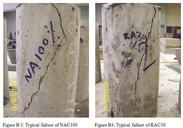
173 APPENDIX-B University of Stellenbosch Page 153
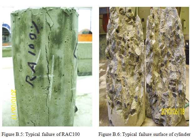
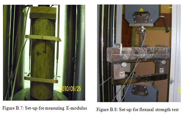
174 University of Stellenbosch Page 154
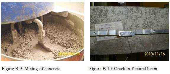
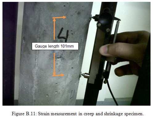
175 University of Stellenbosch Page 155
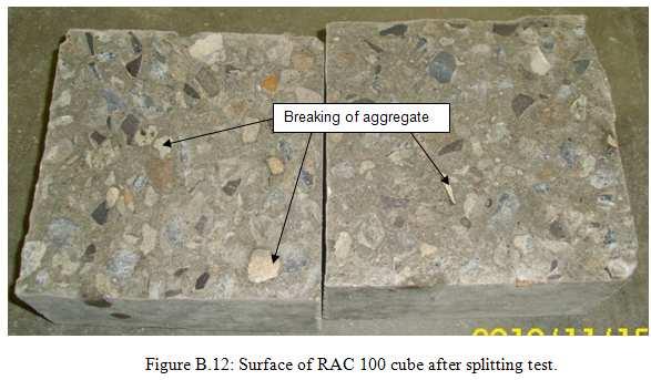
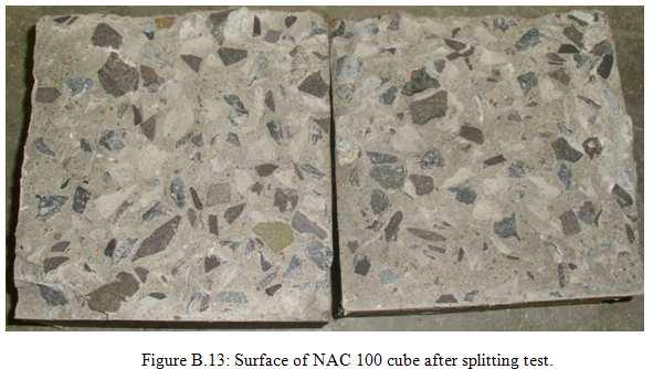
176 University of Stellenbosch Page 156
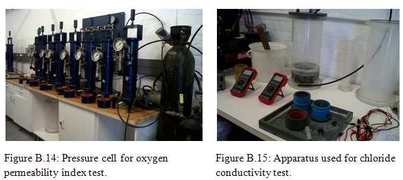
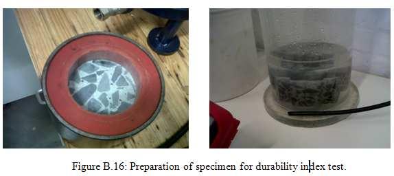
177 University of Stellenbosch Page 157
Study of Partial Replacement of Natural Aggregate by Recycled Aggregate on Concrete
 Study of Partial Replacement of Natural Aggregate by Recycled Aggregate on Concrete Lalramsanga 1, Laldintluanga H 2 1 M.Tech, Civil Engineering Department, Bharath University, India 2 Assistant Professor,
Use of Demolished Concrete Wastes As Coarse Aggregates in High Strength Concrete Production
 Use of Demolished Concrete Wastes As Coarse Aggregates in High Strength Concrete Production Anagha Kalpavalli Civil Department M S Ramaiah Institute of Technology Bangalore, India Dr. S. M. Naik Civil
Utilisation of Recycled Aggregate as Coarse Aggregate in Concrete
 Utilisation of Recycled Aggregate as Coarse Aggregate in Concrete Yong, P.C. 1 and Teo, D.C.L. 2 Abstract In this rapid industrialised world, recycling construction material plays an important role to
Keywords - Recycled Coarse Aggregate (RCA), Compressive Strength, C&D Construction and Demolition Waste
, Compressive Strength, C&D Construction and Demolition Waste") Volume-, Issue-, Mar.-1 EFFECTIVENESS OF USING RECYCLED COARSE AGGREGATES (RCA) IN MAKING HIGH STRENGTH CONCRETE 1 SRINIVAS ANGADI, 2 S SELVAPRAKASH, J S R PRASAD 1,2 Assistant Professor, Institute of
Volume-, Issue-, Mar.-1 EFFECTIVENESS OF USING RECYCLED COARSE AGGREGATES (RCA) IN MAKING HIGH STRENGTH CONCRETE 1 SRINIVAS ANGADI, 2 S SELVAPRAKASH, J S R PRASAD 1,2 Assistant Professor, Institute of
Use of Brick Masonry from Construction and Demolition Waste as Aggregates in Concrete
 Use of Brick Masonry from Construction and Demolition Waste as Aggregates in Concrete Tara Cavalline, PE and David C. Weggel, Ph.D., PE UNC Charlotte 2012 International Concrete Sustainability Conference
Recycled aggregate concrete (RAC)- A sustainable approach for construction industry
- A sustainable approach for construction industry") Recycled aggregate concrete (RAC)- A sustainable approach for construction industry Rajindervir Singh 1, Department of Civil Engineering, Punjab Agricultural University, Ludhiana, Punjab, India Jagmeet
Recycled aggregate concrete (RAC)- A sustainable approach for construction industry Rajindervir Singh 1, Department of Civil Engineering, Punjab Agricultural University, Ludhiana, Punjab, India Jagmeet
A Study on Mechanical Properties of Fiber Reinforced High Strength Concrete using Recycled Coarse Aggregate
 IJIRST International Journal for Innovative Research in Science & Technology Volume 3 Issue 07 December 2016 ISSN (online): 2349-6010 A Study on Mechanical Properties of Fiber Reinforced High Strength
Mechanical Properties of Concrete with Admixed Recycled Aggregate
 Mechanical Concrete with Admixed Recycled Aggregate Shin Elizabeth Shaji Department Civil Engineering Mar Baselios College Engineering and Technology Thiruvananthapuram, India Mr.Jithin J S Department
STUDY ON CONCRETE REPLACED WITH CRUSHED CONCRETE FINE AGGREGATE
 STUDY ON REPLACED WITH CRUSHED FINE AGGREGATE Mrs. Roopa G Sindigi 1, Mr. Devaraja R 2, Mr. Paramesh G A 3 1 Associate Professor, Department of Civil Engineering, Islamiah Institute of technology, Bengaluru-560076
Study of Properties of Concrete using GGBS and Recycled Concrete Aggregates
 Study of Properties of Concrete using GGBS and Recycled Concrete Aggregates Jayalakshmi Sasidharan Nair ICET Muvattupuzha, India Abstract Concrete is playing a significant role in the growth of infrastructural
CONCRETE USING RECYCLED AGGREGATES
 International Journal of Civil Engineering and Technology (IJCIET) Volume 8, Issue 9, September 017, pp. 413 419, Article ID: IJCIET_08_09_049 Available online at http://http://www.iaeme.com/ijciet/issues.asp?jtype=ijciet&vtype=8&itype=9
Recycled Aggregate Concrete, a Sustainable Option from Demolition Concrete Waste- A Percentage Replacement Method
 Recycled Aggregate Concrete, a Sustainable Option from Demolition Concrete Waste- A Percentage Replacement Method Praveen Mathew 1, Jeevan Jacob 2, Leni Stephen 3, Thomas Paul 4 Assistant Professor, Civil
COMPARISON OF PROPERTIES OF FINE AGGREGATE OBTAINED FROM RECYCLED CONCRETE WITH THAT OF CONVENTIONAL FINE AGGREGATES
 COMPARISON OF PROPERTIES OF FINE AGGREGATE OBTAINED FROM RECYCLED CONCRETE WITH THAT OF CONVENTIONAL FINE AGGREGATES Faizanul Haque 1, Syed S.Ashraf 2, Rajat Kumar 3, Ashish Aggrawal 4, Rahil A.Khan 5
Aggregates in Concrete
 Aggregates in Concrete Definitions and Importance of Aggregates Aggregate is a rock like material Used in many civil engineering and construction applications including: Portland cement concrete Asphalt
International Journal of Engineering and Techniques - Volume 4 Issue 3, May June 2018
 RESEARCH ARTICLE OPEN ACCESS Mechanical Properties of Field Demolished Aggregate Concrete Vidya.B 1, Sravani.N 2, Manisha.K, Lakshmana Rao.G 4, Chandra Sekhar.O 5 1 Assistant professor, Department of Civil
Performance of Recycled Aggregate Concrete for M40 Grade
 Performance of Recycled Aggregate Concrete for M40 Grade V.Surya Kiran 1, V.Bala Krishna 2, P.Sowjanya 3 1PG Student, Department of Civil Engineering, SVKR college of Engineering, Andhra Pradesh, India
USAGE OF C&D WASTE IN CONCRETE AS A REPLACEMENT OF NATURAL AGGREGATE
 USAGE OF C&D WASTE IN CONCRETE AS A REPLACEMENT OF NATURAL AGGREGATE ABSTRACT Nikhil Kaushik & V V Arora National Council for Cement and Building Materials, India Construction and demolition (C&D) waste
Properties of Concrete Containing Recycled Fine Aggregate and fly ash
 Properties of Concrete Containing Recycled Fine Aggregate and fly ash S. F. U. Ahmed Dept. of Civil Engineering. Curtin University. Synopsis: This paper reports the properties of concrete containing recycled
Recycling of Concrete
 Recycling of Concrete by T. NAWA Hokkaido University, Graduated School of Engineering Faculty, Division of Sustainable Engineering The Need for Construction and Demolition Waste Minimization In 20 century
Vimalkumar N Patel 1, C D Modhera 2, Krunali Savalia 3 ABSTRACT
 Effect of recycled coarse aggregate manufactured from different industry waste with mineral admixtures on the fresh and hardened properties of concrete Vimalkumar N Patel 1, C D Modhera 2, Krunali Savalia
Evaluation of the Physical Properties of Unbound Base Layer Containing Recycled Aggregates
 International Journal of Environmental Science and Development, Vol. 6, No. 4, April 5 Evaluation of the Physical Properties of Unbound Base Layer Containing Recycled Aggregates H. Taherkhani Abstract
DEVELOPMENT AND STUDY OF BEHAVIOR OF SELF-COMPACTING CONCRETE USING RECYCLED AGGREGATES
 DEVELOPMENT AND STUDY OF BEHAVIOR OF SELF-COMPACTING CONCRETE USING RECYCLED AGGREGATES Arjun B 1, M.Rame Gowda 2 1 M.Tech Student, Department of Civil Engineering, Adichunchanagiri Institute of Technology,
Topic 1 - Properties of Concrete. 1. Quick Revision
 Topic 1 - Properties of Concrete 1. Quick Revision 1.1 Constituent Materials of concrete Concrete is composed mainly of three materials, namely, cement, water and aggregate, and sometimes additional material,
Recycled Concrete Aggregate in Transportation Projects
 Recycled Concrete Aggregate in Transportation Projects 1 Background Aggregates in transportation construction 2.241 billion metric tons of crushed stone (2006) Transportation infrastructure 95% of production
Key Words Student Paper, Technology, Construction Management and Engineering Technology
 Influence of Recycled Aggregates on Mechanical Properties of High Performance Concrete Justin Benge, Purdue University Calumet Jose Pena, Purdue University Calumet Ivan Ortiz, Purdue University Calumet
Reconnaissance of Strength Characteristics of Recron Polyester Fiber Recycled Aggregate Concrete
 Reconnaissance of Strength Characteristics of Recron Polyester Fiber Recycled Aggregate Concrete Mr.V.V.S.Sharma Assistant Professor, Department of Civil Engineering Vishnu Institute of Technology Vishnupur,
IJSRD - International Journal for Scientific Research & Development Vol. 2, Issue 07, 2014 ISSN (online):
:") IJSRD - International Journal for Scientific Research & Development Vol. 2, Issue 07, 2014 ISSN (online): 2321-013 An Experimental Investigation on Strength Behavior of Concrete by Replacing N.C.A with
IJSRD - International Journal for Scientific Research & Development Vol. 2, Issue 07, 2014 ISSN (online): 2321-013 An Experimental Investigation on Strength Behavior of Concrete by Replacing N.C.A with
Comparative Study on performance of concrete with Natural sand and Robo sand
 Comparative Study on performance of with Natural sand and Robo sand P. Bhanu Prakash Reddy #1, V.Sowjanya Vani *2, N.Sunil #3 #1 PG Student, Department of Civil Engineering, GITAM University, Visakhapatnam,
Study of Concrete Involving Use of Quarry dust as Partial Replacement of Fine Aggregates
 IOSR Journal of Engineering (IOSRJEN) ISSN (e): 2250-3021, ISSN (p): 2278-8719 Vol. 05, Issue 02 (February. 2015), V3 PP 05-10 www.iosrjen.org Study of Concrete Involving Use of Quarry dust as Partial
What s in the Mix. Aim of this presentation Basic principles of mix design Overview of constituents Cement Aggregates Coarse Fine.
 What s in The Mix What s in the Mix The aim of this lecture is not to teach you how to perform a mix design but hopefully to help you understand the mix and how it is designed. Aim of this presentation
EXPERIMENTAL INVESTIGATION ON DURABILITY PROPERTIES OF RECYCLED AGGREGATES CONCRETE
 EXPERIMENTAL INVESTIGATION ON DURABILITY PROPERTIES OF RECYCLED AGGREGATES CONCRETE P. Nagi reddy 1, K.Prasadh reddy 2 1Asst. Professor, Dept. Of Civil engineering, Newton s institute of science& technology,
Mechanical Behaviour of Concrete with Recycled Aggregate
 Mechanical Behaviour of Concrete with Recycled Aggregate A. Caggiano 1, C. Faella 2, C. Lima 3, E. Martinelli 4, M. Mele 5, A. Pasqualini 6, R. Realfonzo 7, M. Valente 8 ABSTRACT: This study is aimed at
INFLUENCE OF RECYCLED CONCRETE AGGREGATES ON STRENGTH PARAMETERS OF CONCRETE
 INFLUENCE OF RECYCLED CONCRETE AGGREGATES ON STRENGTH PARAMETERS OF CONCRETE Jitender Sharma 1, Sandeep Singla 2 1 (Civil Engineering, RIMT-IET/PTU, INDIA) 2 (Civil Engineering, RIMT-IET/PTU, INDIA) ABSTRACT
Analysis of Effects of Recycled Aggregates on Properties of Concrete
 Analysis of Effects of Recycled Aggregates on Properties of Concrete Er.Sunil Kumar 1, Er.Vikram Dhillon 2, Er. Jatin Goyal 3 M.Tech Scholar, Department of Civil Engineering, JCDMCOE, Sirsa, India Assistant
STRUCTURAL BEHAVIOUR OF SINGLY REINFORCED OPS BEAMS
 STRUCTURAL BEHAVIOUR OF SINGLY REINFORCED OPS BEAMS D. C. L. Teo 1, M. A. Mannan 2, V. J. Kurian Civil Engineering Program, School of Engineering and Information Technology Universiti Malaysia Sabah, 88999
INTERNATIONAL JOURNAL OF CIVIL AND STRUCTURAL ENGINEERING Volume 6, No 2, 2015
 INTERNATIONAL JOURNAL OF CIVIL AND STRUCTURAL ENGINEERING Volume 6, No 2, 2015 Copyright by the authors - Licensee IPA- Under Creative Commons license 3.0 Research article ISSN 0976 4399 Effect of replacement
EXPERIMENTAL INVESTIGATION IN DEVELOPMENT LOW COST CONCRETE BY USING BRICK POWDER AND QUARTZ DUST
 EXPERIMENTAL INVESTIGATION IN DEVELOPMENT LOW COST CONCRETE BY USING BRICK POWDER AND QUARTZ DUST B.Venkata Srinivasarao M.Tech scholar, Department of Civil Engineering, Chintalapudi Engineering College,
Compressive Strength of Concrete Using Recycled Concrete Aggregate as Complete Replacement of Natural Aggregate
 Compressive Strength of Concrete Using Recycled Concrete Aggregate as Complete Replacement of Natural Aggregate Daniel Yaw Osei, Lecturer, Department of Civil Engineering, Cape Coast Polytechnic, Cape
Flexural Strength Properties of Recycled Aggregate Concrete
 Flexural Strength Properties of Recycled Aggregate Concrete K. Usha Nandhini 1, S. Jayakumar 2, S.Kothandaraman 3 1 Research Scholar of Civil Engineering Department, Pondicherry Engineering College, Pondicherry,
High-Strength Structural Concrete with Recycled Aggregates
 High-Strength Structural Concrete with Recycled Aggregates Arem Naresh P.G Student, Dept of Civil Engineering, Siddhartha Institute of Engineering & Technology, Puttur, A.P.India. ABSTRACT: Recycled aggregates
Fundamentals of Concrete
 Components Cement Water Fine Aggregate Coarse Aggregate Fundamentals of Range in Proportions Advantages of Reducing Water Content: Increased strength Lower permeability Fundamentals of Increased resistance
IJRASET: All Rights are Reserved
 Study on Replacement Level of Concrete Waste as Fine Aggregate in Concrete J. Vengadesh Marshall Raman 1, M. Sriram 2 1 Assistant Professor, Mailam Engineering college, Mailam, Villupuram(Dt) 2 Assistant
EXPERIMENTAL ANALYSIS ON RECYCLED WASTE GLASS IN CONCRETE A.Bharavi
 EXPERIMENTAL ANALYSIS ON RECYCLED WASTE GLASS IN CONCRETE A.Bharavi ABSTRACT Disposal of more than 300 tones waste glass daily derived from postconsumer beverage bottles is one of the major environmental
Concrete with Aggregates from Construction and Demolition Waste in Colombia
 Concrete with Aggregates from Construction and Demolition Waste in Colombia Pedro Quiroga and Nancy Torres Escuela Colombiana de Ingeniería, AK 45 No. 205-59, Bogotá, Colombia, E-mail: ,
Use of steel slag in concrete mixtures
 Use of steel slag in concrete mixtures Nasser Al-Nuaimi, Ramzi Taha, Abdulazeez Kilayil, and Abdelhamid Ben Salem Qatar University, Department of Civil and Architectural Engineering, Doha, Qatar E-mail:
Laboratory Analysis of Fly Ash Mix Cement Concrete for Rigid Pavement.
 RESEARCH ARTICLE OPEN ACCESS Laboratory Analysis of Fly Ash Mix Cement Concrete for Rigid Pavement. Er.Amit Kumar Ahirwar 1, Prof. Rajesh Joshi 2, Er. Kapil Soni 3, 1 Scholar M.Tech (Construction, Technology
The Mechanical Properties of Concrete Prepared with Recycled Aggregates and Crushed Bricks
 The Mechanical Properties of Concrete Prepared with Recycled Aggregates and Crushed Bricks E. Abuharrira, A. Mustafa, M. Ali 1 and A. Elwakeel 2 Abstract This paper demonstrates the effect of introducing
CHAPTER 3 MATERIAL PROPERTIES AND MIX PROPORTIONS
 45 CHAPTER 3 MATERIAL PROPERTIES AND MIX PROPORTIONS 3.1 GENERAL In the present investigation, it was planned to cast M40 & M50 grade concrete with and without supplementary cementitious material such
International Journal of Engineering and Innovative Technology (IJEIT) Volume 2, Issue 4, October 2012
 Volume 2, Issue 4, October 2012") International Journal of Engineering and Innovative Technology (IJEIT) Volume 2, Issue 4, October 2012 A Sustainable Method for Consuming Waste Concrete and Limestone Khalid M. Shaheen 1, Ehab E. Aziz
International Journal of Engineering and Innovative Technology (IJEIT) Volume 2, Issue 4, October 2012 A Sustainable Method for Consuming Waste Concrete and Limestone Khalid M. Shaheen 1, Ehab E. Aziz
Utilization of Waste Foundry Sand and Waste Ceramic Tiles as Partial Replacement for Fine and Coarse Aggregates in Concrete
 Utilization of Waste Foundry Sand and Waste Ceramic Tiles as Partial Replacement for Fine and Coarse Aggregates in Concrete Shruthi H.G 1, Pujitha Ganapathi C², Chaithra R³, Sachin Gowda M 4, Nagesh B.S
STUDY ON THE PERMEABILITY OF THE RECYCLED AGGREGATE CONCRETE USING FLY ASH
 STUDY ON THE PERMEABILITY OF THE RECYCLED AGGREGATE CONCRETE USING FLY ASH V. Bhikshma, Osmania University, India K. Divya, Osmania University, India 37th Conference on OUR WORLD IN CONCRETE & STRUCTURES:
Studies on Scrap Tyre Added Concrete for Rigid Pavements
 From the SelectedWorks of Innovative Research Publications IRP India Winter December 1, 2014 Studies on Scrap Tyre Added Concrete for Rigid Pavements Innovative Research Publications, IRP India, Innovative
Roller Compacted Concrete for M30
 Roller Compacted Concrete for M30 Durga Prasad Student, Department of Civil Engineering, MVR College of Engineering. K.Prudhvi Assistant Professor, Department of Civil Engineering, MVR College of Engineering.
Following are key codes & standards to remember for Civil Estimators to prepare the tender/bid proposal in correct manner.
 CODES & STANDARDS FOR ON-SITE TESTING LABORATORY Following are key codes & standards to remember for Civil Estimators to prepare the tender/bid proposal in correct manner. Codes & Standards are published
Durability And Performance Characteristics Of Recycled Aggregate Concrete
 Durability And Performance Characteristics Of Recycled Aggregate Concrete KK Sagoe Crentsil T Brown AH Taylor CSIRO Building Construction and Engineering Victoria Australia Summary: In recent years, the
with SF. Table 1 shows details of physical properties of concrete mix components. 2.3 Selection of water to cement ratio Mortar mixing was firstly con
 コンクリート工学年次論文集,Vol.36,No.1,214 -Technical Paper- STRENGTH CHARACTERISTICS AND EFFECTIVE CHLORIDE DIFFUSION COEFFICIENT OF RUBBERIZED CONCRETE Nurazuwa MD NOOR *1, Hidenori HAMADA *2, Yasutaka SAGAWA *3
Replacement of Coarse Aggregate by Demolished Brick Waste in Concrete
 IJSTE - International Journal of Science Technology & Engineering Volume 4 Issue 2 August 2017 ISSN (online): 2349-784X Replacement of Coarse Aggregate by Demolished Brick Waste in Concrete Dr. M. N. Hiremath
STRENGTH STUDY ON LATERITE CONCRETE WITH AND WITHOUT SILICA FUME
 STRENGTH STUDY ON LATERITE CONCRETE WITH AND WITHOUT SILICA FUME Lekshmy Rajan 1, Anup Joy 2 1 PG Scholar, Structural Engineering, Department of Civil Engineering, Sree Buddha College of Engineering, Pattoor,
INTERNATIONAL JOURNAL OF CIVIL AND STRUCTURAL ENGINEERING Volume 3, No 1, 2012
 INTERNATIONAL JOURNAL OF CIVIL AND STRUCTURAL ENGINEERING Volume 3, No 1, 2012 Copyright by the authors - Licensee IPA- Under Creative Commons license 3.0 Research article ISSN 0976 4399 Performance of
Aggregates. Introduction. Inert, granular, inorganic materials, which normally consist of stone or stone-like solids.
 Introduction Inert, granular, inorganic materials, which normally consist of stone or stone-like solids. Usage: Alone road bases, fill, drainage layers Particulate Composites - Portland cement concrete
An Experimental Study on Partial Replacement of Cement by Ggbs and Natural Sand by Quarry Sand in Concrete
 An Experimental Study on Partial Replacement of Cement by Ggbs and Natural Sand by Quarry Sand in Concrete Chaithra H L 1, Pramod K 2, Dr. Chandrashekar A 3 1 PG Student, Dept of Civil Engineering, K V
USE OF WASTE COCONUT SHELLS AS SUBSTITUTE FOR COARSE AGGREGATE IN LIGHT-WEIGHT CONCRETE MIXES
 USE OF WASTE COCONUT SHELLS AS SUBSTITUTE FOR COARSE AGGREGATE IN LIGHT-WEIGHT CONCRETE MIXES M.B.M. De Costa 1, D.D.T. Dasanayaka 2, M.N. Tantirimudalige 3, K.M.L.A. Udamulla 4 and T.C. Ekneligoda 5 1,2,3,4,5
A. HIGH-STRENGTH CONCRETE (HSC)
") EFFECTS OF SILICA FUME ON PROPERTIES OF HIGH-STRENGTH CONCRETE Nasratullah Amarkhail Graduate School of Science and Technology, Department of Architecture and Building Engineering Kumamoto University Kumamoto
EFFECTS OF SILICA FUME ON PROPERTIES OF HIGH-STRENGTH CONCRETE Nasratullah Amarkhail Graduate School of Science and Technology, Department of Architecture and Building Engineering Kumamoto University Kumamoto
Experimental Study on Concrete and Cement Plaster Using Partial Replacement of Quarry Rock Dust as Fine Aggregate
 IJSRD - International Journal for Scientific Research & Development Vol. 5, Issue 01, 2017 ISSN (online): 2321-0613 Experimental Study on Concrete and Cement Plaster Using Partial Replacement of Quarry
STRENGTH PROPERTIES OF PARTIAL REPLACEMENT OF COCONUT SHELLS AS COARSE AGGREGATE IN CONCRETE
 Journal of Research in Engineering and Applied Sciences STRENGTH PROPERTIES OF PARTIAL REPLACEMENT OF COCONUT SHELLS AS COARSE AGGREGATE IN CONCRETE K. Rajasekhar and K. Spandana Assistant Professor, Department
Impact of Fly Ash and Silpozz as Alternative Cementitious Material in Crusher Dust Concrete [1]
![Impact of Fly Ash and Silpozz as Alternative Cementitious Material in Crusher Dust Concrete [1]](/thumbs/89/97974119.jpg "Impact of Fly Ash and Silpozz as Alternative Cementitious Material in Crusher Dust Concrete [1]") Impact of Fly Ash and Silpozz as Alternative Cementitious Material in Crusher Dust Concrete [1] S. Jena, [2] K. C. Panda, [3] P. Sarangi [1] Assistant Professor, [2] Associate Professor, [3] Assistant
Impact of Fly Ash and Silpozz as Alternative Cementitious Material in Crusher Dust Concrete [1] S. Jena, [2] K. C. Panda, [3] P. Sarangi [1] Assistant Professor, [2] Associate Professor, [3] Assistant
PREPARATION OF CONCRETE USING GOLD MINE WASTE
 PREPARATION OF CONCRETE USING GOLD MINE WASTE PROJECT REFERENCE NO.: 40S_BE_1708 COLLEGE : PDA COLLEGE OF ENGINEERING, KALABURGI BRANCH : DEPARTMENT OF CIVIL ENGINEERING GUIDE : DR. SURESH G. PATIL STUDENTS
Pennoni Associates, Inc.
 in Bethlehem, Pennsylvania, USA has demonstrated proficiency for the testing of construction materials and has conformed to the requirements established in AASHTO R 18 and the AASHTO Accreditation policies
SUITABILITY OF SINTERED FLY ASH LIGHTWEIGHT AGGREGATE IN STRUCTURAL CONCRETE
 ABSTRACT SUITABILITY OF SINTERED FLY ASH LIGHTWEIGHT AGGREGATE IN STRUCTURAL CONCRETE V V Arora, P N Ojha & Mantu Gupta National Council for Cement and Building Materials, India The paper presents the
EFFECT OF PARTIAL REPLACEMENT OF COARSE AGGREGATE BY JHAMA CLASS BRICK IN CONCRETE
 EFFECT OF PARTIAL REPLACEMENT OF COARSE AGGREGATE BY JHAMA CLASS BRICK IN CONCRETE Mr. G. S. Patil M.E. student P.D.V.V.P.C.O.E., Ahmednagar. maheshgirawale@gmail.com Mr. P. B. Autade Assi. Prof. Dept.
Environmentally-friendly concretes for sustainable building
 Environmentally-friendly concretes for sustainable building V. Corinaldesi & G. Moriconi Department SIMAU, Università Politecnica delle Marche, Ancona, Italy Abstract The concept of sustainable development
Assessment of Recycled Aggregate Concrete
 Modern Applied Science October, 2009 Assessment of Recycled Aggregate Concrete Ismail Abdul Rahman Faculty of Civil and Environmental Engineering Faculty of Mechanical and Manufacturing Engineering, Universiti
Recycling Of Concrete Waste Material from Construction Demolition
 American Journal of Engineering Research (AJER) eissn: 23200847 pissn : 23200936 Volume5, Issue4, pp182191 www.ajer.org Research Paper Open Access Recycling Of Concrete Waste Material from Construction
Flood Testing Laboratories, Inc.
 in Chicago, Illinois, USA has demonstrated proficiency for the testing of construction materials and has conformed to the requirements established in AASHTO R 18 and the AASHTO Accreditation policies established
Puducherry , India. Puducherry , India.
 International Journal of Scientific & Engineering Research Volume 8, Issue 6, June-2017 50 EXPERIMENTAL INVESTIGATIONS ON CONCRETE WITH e-plastic WASTE A.Muthadhi *, A. Mohamed Basid +, R. Madivarma +,
Influence of Silica Fume & Recycled Concrete Aggregates on Mechanical Properties of Concrete
 Influence of Silica Fume & Recycled Concrete Aggregates on Mechanical Properties of Concrete Ranjodh Singh 1, Sudhir Arora 2 1 Assistant Professor, DAV University, Jalandhar, 2 Assistant Professor at DAV
Study on Strength Parameter of Conventional Concrete with Fly Ash and Quarry Dust as a Supplement
 American Journal of Materials Research 2018; 5(2): 35-39 http://www.aascit.org/journal/ajmr ISSN: 2375-3919 Study on Strength Parameter of Conventional Concrete with Fly Ash and Quarry Dust as a Supplement
EXPERIMENTAL STUDY OF POLYPROPYLENE FIBRE INCOPORATED CONCRETE
 EXPERIMENTAL STUDY OF POLYPROPYLENE FIBRE INCOPORATED CONCRETE T.Nanda kumar 1, V.Johnpaul.,M.E 2 and Dr.N.Balasundaram 3 1 PG Student, Department of Civil Engineering, Karpagam University, Coimbatore
What s in the Mix. Aim of this presentation Overview of mix design Overview of constituents Cement Aggregates Coarse Fine.
 What s in The Mix What s in the Mix Aim of this presentation Overview of mix design Overview of constituents Cement Aggregates Coarse Fine Water SCM s Aim of a Mix Design Mix Design is a Scientific Art
A Study on Effective Utilization of Wastes from Construction Industry in Road Construction
 International Journal of Engineering Inventions e-issn: 2278-7461, p-issn: 2319-6491 Volume, Issue 2 [November 2] PP: 1-6 A Study on Effective Utilization of Wastes from Construction Industry in Road Construction
Standard Testing & Engineering, LLC
 Standard Testing & Engineering, LLC dba Standard Testing & Engineering Company in Oklahoma City, Oklahoma, USA has demonstrated proficiency for the testing of construction materials and has conformed to
3- Highway Materials Aggregates
 3- Highway Materials Aggregates Highway Materials/ Aggregates Aggregates are granular mineral particles that are widely used for highway bases, subbases, and backfill. Aggregate are also used in combination
Comparision of Strength For Concrete With Rock Dust And Natural Sand Concrete As Fine Aggregate
 ISSN: 8-96, Vol. 5, Issue 11, (Part - ) November 15, pp.7-51 RESEARCH ARTICLE OPEN ACCESS Comparision of Strength For Concrete With And Natural Sand Concrete As Fine Aggregate V.Ashok Kumar 1, GVD Kiran
A Study on Mechanical Properties of Concrete Subjected to High Temperatures
 International Journal of Civil and Structural Engineering Research ISSN 2348-767 (Online) A Study on Mechanical Properties of Concrete Subjected to High s A. HARIKA¹, Dr. C. SASHIDHAR², Dr. T SURESH BABU³
USE OF FLY ASH, RICE HUSK ASH AND QUARRY DUST FOR MAKING GREEN CONCRETE
 USE OF FLY ASH, RICE HUSK ASH AND QUARRY DUST FOR MAKING GREEN CONCRETE 1 Aishwarya Sushil Sangolkar, 2 Dr. A.M. Badar, 3 Mr. S.R. Satone 1 PG Student, 2 Professor, 3 Assistant Professor Department Of
Strength properties of concrete with partial replacement of sand by bottom ash
 Strength properties of concrete with partial replacement of sand by bottom ash K. Soman Divya Sasi K.A Abubaker MBITS, M.G University Assistant Professor Consulting Structural Engineer MBITS, M.G University
EXPERIMENTAL INVESTIGATION ON STRENGTH AND DURABILITY CHARACTERISTICS OF HIGH PERFORMANCE CONCRETE USING GGBS AND MSAND
 EXPERIMENTAL INVESTIGATION ON STRENGTH AND DURABILITY CHARACTERISTICS OF HIGH PERFORMANCE CONCRETE USING GGBS AND MSAND Christina Mary V. and Kishore CH. Faculty of Building and Environment, Sathyabama
To Improve Mechanical Properties of Concrete Paver Blocks
 IOSR Journal of Mechanical and Civil Engineering (IOSR-JMCE) e-issn: 2278-1684,p-ISSN: 2320-334X, Volume 14, Issue 3 Ver. V. (May - June 2017), PP 147-151 www.iosrjournals.org To Improve Mechanical Properties
PHYSICAL AND MECHANICAL PROPERTIES OF RECYCLED AGGREGATES AND TREATED RECYCLED AGGREGATES
 International Journal of Technical Innovation in Modern Engineering & Science (IJTIMES) Impact Factor: 5.22 (SJIF-217), e-issn: 2455-2585 Volume 4, Issue 8, August-218 PHYSICAL AND MECHANICAL PROPERTIES
CHAPTER 6 POLYPROPYLENE FIBRE REINFORCED GEOPOLYMER CONCRETE COMPOSITES
 113 CHAPTER 6 POLYPROPYLENE FIBRE REINFORCED GEOPOLYMER CONCRETE COMPOSITES 6.1 GENERAL This chapter describes the effect of addition of polypropylene fibres on the strength characteristics of geopolymer
Effect of Recycled Coarse Aggregate on Concrete Properties
 Effect of Recycled Coarse Aggregate on Concrete Properties Fathei Ramadan salehlamein 1, Mochamad.Solikin 2, Ir.sriSunarjono 3 Student, Post Graduate Civil Engineering Programs Universities MUHAMMADIYAH
UTILIZATION OF PLASTIC WASTE IN CONCRETE AS A PARTIAL REPLACEMENT OF FINE AGGREGATE
 UTILIZATION OF PLASTIC WASTE IN CONCRETE AS A PARTIAL REPLACEMENT OF FINE AGGREGATE S. Das 1*, M. T. Alam 2 & I. Chowdhury 2 1 Institute of Earthquake Engineering Research, Chittagong University of Engineering
An Experimental Investigation on Flexural Behavior of Recycle Aggregate Fiber Reinforcement Concrete
 International Research Journal of Engineering and Technology (IRJET) e-issn: 239-006 Volume: 02 Issue: 04 July-201 www.irjet.net p-issn: 239-0072 An Experimental Investigation on Flexural Behavior of Recycle
EFFECT ON MECHANICAL PROPERTIES OF CONCRETE USING NYLON FIBERS
 EFFECT ON MECHANICAL PROPERTIES OF CONCRETE USING NYLON FIBERS Nitin 1, Dr. S.K. Verma 2 1 PG student, Dept. of Civil Engineering (Structures), PEC University of technology, Chandigarh, India. 2 Associate
The Use of Recycled Building Rubble in the Reconstruction of Demolished Buildings
 The Use of Recycled Building Rubble in the Reconstruction of Demolished Buildings Hisham Qasrawi, Senior lecturer, Civil Engineering, Faculty of Engineering, The Hashemite University Email: Qasrawi@hu.edu.jo
Correlation between flexural strength of natural aggregate concrete and recycled aggregate concrete
 Correlation between flexural strength of natural aggregate concrete and recycled aggregate concrete Manjunath M 1 and Prakash K B 2 1 Research scholar, Dept. of Civil engineering, Walchand College of Engineering,
Crushed concrete as concrete aggregate in the manufacture of reinforced concrete structures
 Crushed concrete as concrete aggregate in the manufacture of reinforced concrete structures Myhammet Fachratov 1,* 1 Moscow State University of Civil Engineering, Yaroslavskoe shosse, 26, Moscow, 129337,
International Journal on Emerging Technologies 7(1): 5-10(2016)
: 5-10(2016)") e t International Journal on Emerging Technologies 7(1): 5-10(2016) ISSN No. (Print) : 0975-8364 ISSN No. (Online) : 2249-3255 An Experimental Study on Strength of Concrete by Partial Replacement of Cement
e t International Journal on Emerging Technologies 7(1): 5-10(2016) ISSN No. (Print) : 0975-8364 ISSN No. (Online) : 2249-3255 An Experimental Study on Strength of Concrete by Partial Replacement of Cement
Strength Properties of Concrete Using Crumb Rubber with Partial Replacement of Fine Aggregate
 Strength Properties of Concrete Using Crumb Rubber with Partial Replacement of Fine Aggregate S.Selvakumar 1, R.Venkatakrishnaiah 2 P.G. Student, Department of Civil Engineering, Adhiparasakthi Engineering
Strength Characteristics of Concrete Mix by Replacing Fine Aggregates with Industrial Sand
 International Journal of Scientific and Research Publications, Volume 6, Issue 5, May 2016 729 Strength Characteristics of Concrete Mix by Replacing Fine Aggregates with Industrial Sand Gaurav Sharma *,