The Pultex Pultrusion Design Manual
|
|
|
- Marsha Hill
- 6 years ago
- Views:
Transcription

1 The Pultex Pultrusion Design Manual of Standard and Custom Fiber Reinforced Polymer Structural Profiles Imperial Version Volume 5 Revision 6 Featuring Pultex Standard Structural Profiles Pultex SuperStructural Profiles Nuclear test tower constructed using Pultex Standard Structural Profiles Creative Pultrusions, Inc. reserves the right to edit and modify literature, please consult the web site for the most current version of this document.
2 The first Pultex Design Manual was published in The New and Improved Pultex Pultrusion Design Manual of Standard and Custom Fiber Reinforced Polymer Structural Profiles, 2004 Edition, Volume 5 Revision 6 is a tool for engineers to specify Pultex pultruded standard structural profiles. Creative Pultrusions, Inc. consistently improves its information to function as a solid reference for engineers. No portion of this Design Manual may be reproduced in any form without the prior written consent of Creative Pultrusions, Inc. Volume 5 - Revision 6 Copyright 2017 by Creative Pultrusions, Inc. All Rights Reserved Creative Pultrusions, Flowgrip, Pultex, Supergrate, SUPERPILE, Superplank, SuperLoc, SuperWale and Superdeck are registered trademarks of Creative Pultrusions, Inc. Superstud!, Superstud! /Nuts!, SUPURTUF, Tuf-dek, SuperCap and SuperRod are trademarks of Creative Pultrusions, Inc. Contents i
3 The New and Improved Pultex Pultrusion Design Manual of Standard and Custom Fiber Reinforced Polymer Structural Profiles, including Imperial Measurements Table of Contents Volume 5 - Revision 6 Page Numbers Chapter 1 Introduction To Pultrusion Pultex Pultex Pultrusion Process Process Advantages... 3 Raw Materials Used in the Pultrusion Process Pultex Resin Systems Chapter 2 Value Engineering Design Benefits Applications Cost Analysis for Standard and Custom Profiles Raw Material Advantages... 4 Fabrication Advantages... 4 Shipping Advantages... 4 Chapter 3 Physical And Mechanical Properties Introduction to Design with Pultruded Composites... 1 Fiber Properties... 1 Resin Properties... 2 Fillers... 2 Imperial Material Properties Sheets Material Properties of Pultex Fiber Reinforced Polymer Structural Profiles Material Properties of Pultex Fiber Reinforced Polymer Flat Sheets Material Properties of Pultex Fiber Reinforced Polymer Rods and Bars... 7 Material Properties of Superstud!/Nuts! Square Nuts and Isoplast* Flanged Hex Nuts Fiber Reinforced Polymer Fastener Systems... 8 Material Properties of Pultex SuperStructural Profiles Wide Flange and I-Sections Material Properties of Pultex SuperStructural Profiles Angles Procedures for Obtaining Properties Safety Factors Elements of Sections Imperial Elements of Section *Trademark of The Dow Chemical Company ii Contents
4 The New and Improved Pultex Pultrusion Design Manual of Standard and Custom Fiber Reinforced Polymer Structural Profiles, including Imperial Measurements Table of Contents Volume 5 - Revision 6 Page Numbers Chapter 4 Load Tables For Flexural Members And Connections Beam Deflections... 1 Allowable Stresses... 1 Lateral Torsional Buckling Stress Calculations for Channels Local and Global Buckling of FRP Channels Beam Deflection Formula Examples of Beam Selection of Pultex Profiles used as Flexural Members Channel Selection Example Nomenclature Introduction to Pultex SuperStructural Profiles Comparison of Standard Structural Profiles and Pultex SuperStructural Profiles Span/Deflection Ratio Conversion Tables Allowable Uniform Load Tables Connections Clip Connection Load Tables with Pultex SuperStructural Profiles Bolt Hole Bearing Capacity Design Example Using the Clip Connection Charts Moment of Capacity of Pultex SuperStructural Angles Designing a Connection with a Coped Flange End Notes Chapter 5 Load Tables For Compression Members Load Tables For Compression Members... 1 Introduction... 2 Pultex Column Test Program Nomenclature... 9 Tables for Allowable Compressive Stresses and Loads Imperial Tables for Allowable Compressive Stresses and Loads Biography Chapter 6 Environmental Considerations Temperature... 1 Weathering... 1 UV Stabilizers... 1 Resistance to Chemicals and Reagents... 2 Chemical Compatibility Guide Contents iii
5 The New and Improved Pultex Pultrusion Design Manual of Standard and Custom Fiber Reinforced Polymer Structural Profiles, including Imperial Measurements Table of Contents Volume 5 - Revision 6 Page Numbers Chapter 7 Custom Profile Design Wall-Section Thickness... 1 Radius Design Shrinkage... 2 Surface Appearance and Performance Parting Lines... 3 Localized Stiffening... 3 Undercuts... 3 Dimensional Tolerances... 3 Designer Checklist Notes... 6 Chapter 8 Quality Assurance And Standard Tolerances Quality Assurance System... 1 Standard Tolerances Standard Dimensional Tolerances for Pultruded Shapes Fabrication (CPQ )...9 Chapter 9 Fabrication Techniques Fabrication Techniques Fabrication of Pultex Structural Profiles Adhesives/Bonding... 3 Advantage of Adhesives Bonded Shear Joint Concepts Surface Preparations... 5 Adhesives Comparison Guide used with Pultex Profiles... 6 Comparison of Joining Techniques... 6 Machining Operations... 7 Cutting Procedures... 7 Operating Tips Drilling... 8 Grinding... 9 Turning Routing Punching Press Tonnage Requirements Shear Angle in Punching Other Useful Guidelines for Punching Shearing iv Contents
6 The New and Improved Pultex Pultrusion Design Manual of Standard and Custom Fiber Reinforced Polymer Structural Profiles, including Imperial Measurements Table of Contents Volume 5 - Revision 6 Page Numbers Chapter 9 Fabrication Techniques (cont d) Painting Surface Preparation Joining Pultex Structural Profiles Mechanical Fastenings Notes Chapter 10 Writing Specifications For Pultex Structural Profiles Writing Specifications Appendices Appendix A Appendix B Works Cited... 1 Pultex Product Availability List Imperial Pultex Product Availability List Creative Pultrusions, Inc. believes the information put forth in this Design Manual to be as accurate and reliable as we can ascertain as of the date of publication. However, Creative Pultrusions, Inc. does not warrant that the information hereunder will not infringe the claims of any United States or other patents covering products or processes, or the use thereof in combination with other products or in the operation of any process. User also agrees to indemnify and hold Creative Pultrusions, Inc. harmless from and against any and all losses, damages, and expenses (including attorney fees and other costs of defending any action) that Creative Pultrusions, Inc. may sustain or incur as a result of any claim, in connection with the use of the information in this manual. Contents v
7

8 Chapter 1 Introduction to Pultrusion Pultex standard structural profiles are used in many highly-corrosive applications. Established in 1973, Creative Pultrusions is located in Alum Bank, Pennsylvania, and is a subsidiary of Hill & Smith Holdings PLC, an international group with leading positions in the design, manufacture and supply of infrastructure products and galvanizing services to global markets. It serves its customers from facilities principally in the UK, France, USA, Thailand, Sweden, Norway, India and Australia. Headquartered in the UK and quoted on the London Stock Exchange (LSE: HILS.L), Hill & Smith Holdings PLC employs some 3,800 staff across 55 sites, principally in 8 countries. Pultex is the registered trademark of Creative Pultrusions, Inc. (CP) for products made by the pultrusion process. Pultex profiles are Pultruded Fiber Reinforced Polymer (FRP) components, manufactured from a wide variety of high performance thermosetting resins and reinforcements, classifying pultrusion as a structural engineering material. As a result, Pultex profiles have been used extensively in many industries for construction, corrosion-resistant, electrical/electronic, transportation, consumer and water/wastewater applications. Within the last two decades, the pultrusion process has been used by the design engineer as having the capability of manufacturing products that solve many modern problems. As a result, high-strength, lightweight and maintenance-free products and structures have been designed and built. The New and Improved Pultex Pultrusion Design Manual is developed to aid the design engineer in understanding the pultrusion process and how various elements of the process and design affect the performance and cost of the final product. The information provided is the result of many years of participation with industries worldwide. Applications vary from the development of new high-performance springs and bumpers for the automotive industry to corrosion-resistant structural I-beams, channels and angles for the chemical processing industry. With The New and Improved Pultex Pultrusion Design Manual, you, the design engineer, will share in the knowledge and experience to assist in the design of your future pultrusion requirements. Chapter 1 1


9 Bridges are easily installed in hard-to-access areas. Fiberglass platform systems are ideal in highly corrosive areas. An integrated building system is lightweight, easy to erect and maintenance-free. Pultex Pultrusion Process 2 Chapter 1


10 Pultex Pultrusion Process (cont d) Pultrusion is a continuous molding process using fiber reinforcement in polyester or other thermosetting resin matrices. Pre-selected reinforcement materials, such as fiberglass roving, mat or cloth, are drawn through a resin bath in which all material is thoroughly impregnated with a liquid thermosetting resin. The wet-out fiber is formed to the desired geometric shape and pulled into a heated steel die. Once inside the die, the resin cure is initiated by controlling precise elevated temperatures. The laminate solidifies in the exact cavity shape of the die, as it is continuously pulled by the pultrusion machine. Process Advantages The process provides maximum flexibility in the design of pultruded FRP profiles. Currently, profiles up to 72 inches wide and 21 inches high are possible. Since the process is continuous, length variations are limited to shipping capabilities. Specific strength characteristics can be designed into the composite, optimizing laminate performance for a particular application by strategic placement of high performance reinforcements. Color is uniform throughout the cross section of the profile, eliminating the need for many painting requirements. Processing capabilities include the production of both simple and complex profiles, eliminating the need for much post-production assembly of components. Pultex profiles can result in more satisfactory performance of your finished products and structures. Raw Materials Used in the Pultrusion Process Each resin mix is formulated carefully to suit application requirements. Roving and mat are of major importance in determining physical properties. Resin Selected high performance polyester resins are combined with suitable fillers, catalysts, UV inhibitors and pigments to formulate the resinous matrix, binding the fibers together and providing the structural corrosion resistance and other properties required. Although the vast majority of applications can be serviced by the variety of polyester resins available, certain application requirements of higher strength or corrosion resistance can be satisfied with the selection of vinyl ester. Chapter 1 3
11 Roving Fiberglass roving provides the high longitudinal strength of pultruded products. The amount and location of these reinforcements can be determined in the design stage and can alter the subsequent physical properties of the finished product. Roving also provides the tensile strength needed to pull the other reinforcements through the die; therefore, it is a necessary ingredient in the profile design. Mat Continuous strand mat provides the most economical method of obtaining a high degree of transverse physical properties. The mats are layered with roving; this process forms the basic composition found in most pultruded products. The ratio of mat to roving determines the relationship of transverse to longitudinal physical properties. Veil Since pultrusion is a low-pressure process, fiberglass reinforcements normally appear close to the surface of the product. These can affect the appearance, corrosion resistance or handling of the products. Surface veils can be added to the laminate construction to displace the reinforcement from the surface adding a resin-rich finish to the profile. The two most commonly used veils are A-glass and polyester. Pultex Resin Systems Resin mixtures, glass content and their combination can be altered to achieve special properties in a profile due to the versatility of the pultrusion process. The specific resin formula may be adjusted for each profile due to processing requirements. Table 1-1 Available Resin Systems Pultex Resin Series 1500 Polyesters 1525 Fire Retardant Polyesters 1600 Vinyl esters 1625 Fire Retardant Vinyl esters 2020 Low Profile Modified Polyester Resin System Characteristics Good chemical resistance combined with high mechanical and electrical properties. A flame spread rating of 25 or less when tested per ASTM E-84 plus the attributes of 1500 Series profiles. UL 94 VO rating also available on request. Excellent corrosion resistance, as well as, improved physical properties and elevated service temperature capabilities. Same as Series 1600 plus the added bonus of a 25 or less rating per ASTM E84 and low smoke generation. Profiles requiring optimum surface finish Typical Applications Standard Structurals used in moderately corrosive environments Crossing gate arms Dunnage bars Ladders Fire retardant standard structurals High performance standard structurals High performance standard structurals for severely corrosive environments Transportation 4 Chapter 1


12 Table 1-1 Available Resin Systems (cont d) Pultex Resin Series Characteristics Halogen free, low flame and smoke. Typical Applications 3535 Mass Transit Modified Polyester Electrical Reference The Pultex Product Availability List for stocked items. Other special resin systems are available; please contact the Engineering Department of Creative Pultrusions, Inc. Woven and Stitched Fabric When the mix of required physical properties is not satisfied by conventional mat roving construction, selected fabrics can be used to meet the end use requirements. Varieties of these products can be used by themselves or in conjunction with the standard mat roving construction to obtain the necessary results. The fiberglass fabrics are available in balanced, high longitudinal, high transverse or ± 45 multi-ply construction. Since these materials are more costly, the composites using these reinforcements are more expensive than standard construction pultrusion. Other Reinforcing Material Carbon and aramid fibers are also used in the pultrusion process in roving, woven fabric forms, or in combination with fiberglass. These high modulus fibers add considerable stiffness to the composite. Care must be taken when designing profiles with carbon and aramid fiber materials since they are more costly. The composite should be designed for optimum performance. Surfacing veils enhance the finished profile and increase corrosion resistance. Woven/stitched goods increase transverse properties of pultruded profiles. Chapter 1 5
13

14 Chapter 2 Value Engineering Design Benefits Many advantages exist in using Pultex Profiles, compared to conventional materials, such as steel, aluminum, wood or other plastics. Analyzing the benefits of Pultex can mean a cost savings to you. The first step is to compile the total cost of the application, which includes: tooling, raw materials and any required fabrication. Costs are easily obtained from the Sales and Estimating Department of Creative Pultrusions. The second step is to add the cost savings that would be realized by you and the end user, in comparison to using conventional construction materials. These savings are realized in reduced maintenance cost, lower installation cost and reduced freight, due to lighter weight properties. Savings in the life cycle of the product should be considered with the product s original cost when making cost comparisons. Light weight, high strength and electrical insulating properties make FRP profiles ideal for third-rail coverboard on electrical mass transit systems around the world. Chapter 2 1
15 Table 2-1 Features & Benefits of Pultex Profiles Features Description Benefits Strength Unit strength in tension, flexure, and compression is approximately 20 times that of steel when properties are combined on the basis of unit density Structural design capabilities Optional strength in desired directions Exceptionally high impact strengths Lightweight Corrosion Resistance Electrical Insulation Part Consolidation Dimensional Stability Thermal Insulation Applications Density of Pultex is 20% of steel and 60% of aluminum Unaffected by a wide range of corrosive chemicals and environments Structural strength and rigidity are provided with dielectric material. Many individual components can be combined into one large profile. Stretch-, warp-, and swell-resistant over a wide range of temperatures and physical stresses. Low thermal conductivity rating of 1/250 of aluminum; 1/60 of steel Higher performance at less weight Reduced shipping costs Reduced operational energy demands Reduced labor expense for installations Easily handled Assembled and installed with ease Minimal maintenance costs Long-term safety Installation longevity and increased service life Outdoor storage capabilities Lower cost performance ratio Less need for replacements Less components for assemblies Non-magnetic Additional safety factors Predictable insulation values Reduced assembly costs Reduced inventory requirements Smooth aerodynamic surfaces Improved reliability No permanent set under high stress Reduced damage to structure assemblies Easy to repair misused parts Close tolerances Reduced insulation thickness requirements Reduced energy operation requirements No condensation problems Construction/Industrial Bridges Bulk head frames Cable trays Complete building systems Cooling tower components Flooring supports Grating and supports Pipe supports Prefabricated walkways, platforms and handrail systems Structural supports for process equipment Trusses and joists Wind blades Window frames 2 Chapter 2
16 Applications (cont d) Automotive Consumer Automobile springs Automotive leaf springs and bumpers Bus components Bus window latch supports Dunnage bars Roll-up doors/ insulated roll-up door panels Spring bumpers Tank supports Truck/trailer wall posts Ladders Light poles Mop, broom and brush handles Pruning poles Rake handles Shovel handles Wastewater Cell partitions Scrubber components Traveling water screens Water/waste water treatment sludge flights Electrical Marine Composite utility poles Crossarms Crossing gate arms Electrical enclosures Mist eliminators Mounting braces & backboards Switch gear components Third rail coverboards Walk-in refrigeration door jambs Boat dock power posts Fender pilings Sheetpiles Cost Analysis for Standard and Custom Profiles Careful study of end-use requirements for an application will establish the potential for use of Pultex. If possible, designs should be drawn and the commercial feasibility determined. The applied cost of the end uses of a pultruded profile is the sum of the tooling, raw material and fabrication, plus the additional consideration of transportation, assembly and/or erection/installation cost. In many cases of mechanical design or prototyping, standard Pultex Profiles can be used. The most economical alternative for the designer is to evaluate the material, as it may eliminate elements of cost, such as development time, tooling, and manufacturing for limited quantity runs. Even custom profiles can be effectively fabricated and/or assembled from available standard profiles, aiding the designer in determining the feasibility of an idea with minimal cost. Chapter 2 3
17 Tooling Costs When the feasibility is determined and a custom profile is required, the following factors must be considered: 1. Products selected from the list of available Pultex standard structural profiles involve no additional tooling cost and are normally available in any quantity through the distribution network. 2. Tooling costs for custom pultruded profiles are dependent on the complexity of the profile and the volume requirements, and are often less than those for traditional materials. Raw Material Advantages Pultex 1500 and 1525 Series are produced with high performance grades of polyester resin, continuous strand mat and roving. The combination provides a quality product that is economically priced. When the application requires higher performance ratings for standard or custom profiles, it can be engineered with specialized reinforcements and resins. Although premium raw materials also affect the cost of a product by adding complexity and possibly lowering production rates, the benefits realized can usually justify the additional costs. Highperformance resins or specialized reinforcements can improve usable life or ultimate strength of a profile. Fabrication Advantages Creative Pultrusions provides a full-service Fabrication Network that offers painting, punching, multihead drilling and assembly. If you choose to do your own fabrication, Creative Pultrusions can provide recommendations on methods and equipment to be used based on extensive experience. Chapter 9 provides many helpful hints in determining the optimum fabrication techniques. Shipping Advantages Shipping of components or sections is one segment of costs sometimes neglected in early design stages. It particularly applies to glass-reinforced products, such as pultrusions, due to their lower density. In most shipments, the volume of a shipping container is completely filled before the maximum shipping weight is reached; therefore, it is important for the designer to consider this fact when designing the profile. The ability to stack or crate the profile will affect the end-product costs. Another consideration is length. Since pultrusion is a continuous process, it allows the designer to use any length product possible. The only limitation is that profiles must be practical shipping lengths. Standard shipping lengths are usually 45 feet or less to fit the length of most common carriers. Rods or smaller profiles, which can be coiled, have a theoretically unlimited length, although there are some process limitations. Chapter 2 4
18 Chapter 3 Physical and Mechanical Properties Continuous Strand Mat Continuous Roving Surface Veil Continuous Strand Mat Pultrusion Composite Diagram Continuous Roving Continuous Strand Mat Surface Veil Introduction To Design With Pultruded Composites A pultrusion is a composite of several materials and reinforcements. It presents the opportunity to design product components with properties to meet specific needs. Fiber reinforcements and loadings can be varied to produce a wide range of structural properties in the end product. Typical structural items contain 45% to 75% glass by weight. This composite type is widely used in the pultrusion industry for determining the standard mechanical properties of pultrusion, and can be modified, if necessary, for special applications. Tensile strengths, for example, can vary from 40 MPa to 1000 MPa, depending on the glass loading, fiber orientation and resin selection. Fiber Properties A variety of continuous and woven reinforcement types is also available to the designer. The four major types are E-GLASS, S-GLASS, ARAMID and CARBON. The primary type used is E-glass. Other reinforcements are more costly; and, therefore, used more sparingly in construction. Table 3-1 Typical Properties of Fibers Used in Pultruded Structural Profiles Properties are displayed below for virgin fibers, as manufactured. Property E-Glass S-Glass Aramid Carbon Density lbs/in Tensile Strength (psi) 500, , , , ,000 Tensile Modulus (10 6 psi) Elongation to break (%) Fiber reinforcements are available in a variety of single-strand woven, braided, stitched, and knitted goods, thus adding to the range of properties of the end composite. Chapter 3 1
19 Resin Properties Determination of resin is controlled by factors such as corrosive environments, temperature exposure, and flame retardancy. Polyesters are the primary resins used in pultrusion. A wide range of polyesters is available with distinct characteristics. The capabilities and needs for these various resins can only be determined by end-use applications. For the selection of a particular polyester, the designer should consult Creative Pultrusions. Fire-retardant polyesters are also available. Fire retardancy can be altered with the proper blending of different resins. Some of the obtainable results on flammability specifications and tests are presented further in the Material Properties. For superior fire retardancy, phenolic or other specialty resins may be used. Vinyl ester resins are also commonly used in the pultrusion process. They are used to improve the chemical resistance of the laminate. Because of their chemistry with glass reinforcements, physical properties of the laminate can be expected to increase up to 15%. Epoxy resins are typically used with carbon fiber reinforcements in applications in which high stiffness and strength requirements are critical. They can also be used with E-glass to improve the physical properties. Table 3-2 Typical Properties of Resins Used in Pultruded Structural Profiles Property Polyester Vinyl ester Epoxy Test Method Tensile Strength (psi) 11,200 11,800 11,000 ASTM D638 % Elongation ASTM D638 Flexural Strength (psi) 17,800 20,000 16,700 ASTM D790 Flexural Modulus (10 6 psi) ASTM D790 Heat Distortion Temperature ( F) ASTM D648 Short Beam Shear (psi) 4,500 5,500 8,000 ASTM D2344 Fillers Various fillers are also used in the pultrusion process. Aluminum silicate (kaolin clay) is used for improved chemical resistance, opacity, good surface finish and improved insulation properties. Calcium carbonate offers improved surfaces, whiteness, opacity and general lowering of costs. Alumina trihydrate and antimony trioxide are used for fire retardancy. Alumina trihydrate can also be used in conjunction with clays for improved insulation properties. 2 Chapter 3
20 MATERIAL PROPERTIES Pultex Fiber Reinforced Polymer Structural Profiles Rectangular Tubes, Channels, Angles, Square Tubes, Round Tubes Includes all angles except 4 x 1/4, 4 x 3/8, 6 x 3/8 and 6 x 1/2, which are SuperStructurals. Please consult the Pultex Fiber Reinforced Polymer SuperStructural Profiles Angles Material Properties 1500 Series - Thermoset Polyester Olive Green 1525 Series - Thermoset Polyester Class 1 FR Slate Gray (Dark Gray) 1625 Series - Thermoset Vinyl Ester Class 1 FR Beige The following data was derived from ASTM coupon and full section testing. The results are average values based on random sampling and testing of production lots. Composite materials are not homogeneous; and therefore, the location of the coupon extraction can cause variances in the coupon test results. Creative Pultrusions publishes an average value of random samples from production lots. Property (coupon values) ASTM Test Units 1500/1525 Series 1625 Series Mechanical Tensile Strength (LW) D638 psi 33,000 37,500 Tensile Strength (CW) D638 psi 7,500 8,000 Tensile Modulus (LW) D psi Tensile Modulus (CW) D psi Compressive Strength (LW) D695 psi 33,000 37,500 Compressive Strength (CW) D695 psi 16,500 20,000 Compressive Modulus (LW) D psi Compressive Modulus (CW) D psi Flexural Strength (LW) D790 psi 33,000 37,500 Flexural Strength (CW) D790 psi 11,000 12,500 Flexural Modulus (LW) D psi Flexural Modulus (CW) D psi Modulus of Elasticity Full Section psi (Channels) Full Section psi (Square and Rectangular Tubes) Full Section psi Shear Modulus Full Section psi Interlaminar Shear (LW) 3 D2344 psi 4,500 4,500 Shear Strength By Punch (PF) D732 psi 5,500 6,000 Notched Izod Impact (LW) D256 ft-lbs/in Notched Izod Impact (CW) D256 ft-lbs/in 4 5 Maximum Bearing Strength (LW) D953 psi 30,000 30,000 Maximum Bearing Strength (CW) D953 psi 18,000 18,000 Poisson s Ratio (LW) D3039 in/in Poisson s Ratio (CW) D3039 in/in In-plane Shear (LW) Modified D psi 7,000 7,000 LW = lengthwise CW = crosswise PF = perpendicular to laminate face Additional properties located on page 4 Chapter 3 3
21 MATERIAL PROPERTIES Pultex Fiber Reinforced Polymer Structural Profiles Rectangular Tubes, Channels, Angles, Square Tubes, Round Tubes Includes all angles except 4 x 1/4, 4 x 3/8, 6 x 3/8 and 6 x 1/2, which are SuperStructurals. Please consult the Pultex Fiber Reinforced Polymer SuperStructural Profiles Angles Material Properties Property (coupon values) ASTM Test Units 1500/1525 Series 1625 Series Physical Barcol Hardness 1 D Water Absorption D570 % Max Density D792 lbs/in Specific Gravity D Coefficient of Thermal Expansion (LW) D in/in/ F Thermal Conductivity (PF) C177 BTU-in/ft 2 /hr/ F 4 4 Electrical Arc Resistance (LW) D495 seconds Dielectric Strength (LW) D149 KV/in Dielectric Strength (PF) D149 volts/mil Dielectric Constant (PF) Pultex uses a synthetic surface veil that reduces the Barcol Hardness, but does not reflect lack of cure. 2 Full section testing based on a 3-point bend with simply supported end conditions (Reference The New and Improved Pultex Pultrusion Global Design Manual, Appendix B, for details). 3 Tested on a 3:1, span to depth ratio. 4 Follow ASTM D2344, but rotate coupon 90 (cut section of coupon length faces up). 5 In-plane Shear (CW) values for square tubes and rectangular tubes = 2,500 psi; angles = 3,800 psi ASTM Test Value Value Property Flammability Classification UL94 (VO) (VO) Tunnel Test ASTM E Max 25 Max Flammability Extinguishing ASTM D635 Self extinguishing Self extinguishing NBS Smoke Chamber ASTM E UNC 13 UNC 11 UNC 10 UNC 8 UNC Creative Pultrusions, Inc. believes the information put forth in this property sheet to be as accurate and reliable as of the date of publication. However, we assume no obligation or liability, which may arise as a result of its use. While Creative Pultrusions, Inc. has no knowledge that the information put forth infringes any valid patent, it assumes no responsibility with respect thereto and each user must satisfy oneself that one s intended application process or product infringes no patent. 4 Chapter 3
22 MATERIAL PROPERTIES Pultex Fiber Reinforced Polymer Flat Sheets 1500 Series - Thermoset Polyester Olive Green 1525 Series - Thermoset Polyester Class 1 FR Slate Gray (Dark Gray) 1625 Series - Thermoset Vinyl Ester Class 1 FR Beige The following data was derived from ASTM coupon and full section testing. The results are average values based on random sampling and testing of production lots. Composite materials are not homogeneous; and therefore, the location of the coupon extraction can cause variances in the coupon test results. Creative Pultrusions publishes an average value of random samples from production lots. Property (coupon values) ASTM Test Units 1500/1525 Series 1625 Series Mechanical Flexural Strength, Flatwise (LW) D790 psi 35,000 35,000 Flexural Strength, Flatwise (CW) D790 psi 15,000 15,000 Flexural Modulus, Flatwise (LW) D psi Flexural Modulus, Flatwise (CW) D psi Tensile Strength (LW) D638 psi 20,000 20,000 Tensile Strength (CW) D638 psi 10,000 10,000 Tensile Modulus (LW) D psi Tensile Modulus (CW) D psi Compressive Strength, Edgewise (LW) D695 psi 24,000 24,000 Compressive Strength, Edgewise (CW) D695 psi 16,000 16,000 Compressive Modulus, Edgewise (LW) D psi Compressive Modulus, Edgewise (CW) D psi Notched Izod Impact (LW) D256 ft-lbs/in Notched Izod Impact (CW) D256 ft-lbs/in 5 5 Bearing Strength (LW) D953 psi 32,000 32,000 Bearing Strength (CW) D953 psi 32,000 32,000 Poisson s Ratio (LW) D3039 in/in Poisson s Ratio (CW) D3039 in/in Physical Barcol Hardness 1 D Water Absorption D570 % Max Density D792 lbs/in Specific Gravity D Coefficient of Thermal Expansion (LW) D in/in/ F Electrical Arc Resistance (LW) D495 seconds Dielectric Strength (LW) D149 KV/in Dielectric Strength (PF) D149 volts/mil Dielectric Constant (PF) Pultex uses a synthetic surface veil that reduces the Barcol Hardness, but does not reflect lack of cure. Additional Properties located on page 6 Chapter 3 5
23 MATERIAL PROPERTIES Pultex Fiber Reinforced Polymer Flat Sheets (cont d) ASTM Test Value Value Property Flammability Classification UL94 (VO) (VO) Tunnel Test ASTM E Max 25 Max Flammability Extinguishing ASTM D635 Self extinguishing Self extinguishing NBS Smoke Chamber ASTM E Creative Pultrusions, Inc. believes the information put forth in this property sheet to be as accurate and reliable as of the date of publication. However, we assume no obligation or liability, which may arise as a result of its use. While Creative Pultrusions, Inc. has no knowledge that the information put forth infringes any valid patent, it assumes no responsibility with respect thereto and each user must satisfy oneself that one s intended application process or product infringes no patent. 6 Chapter 3
24 MATERIAL PROPERTIES Pultex Fiber Reinforced Polymer Rods And Bars 1500 Series - Thermoset Polyester Olive Green 1525 Series - Thermoset Polyester Class 1 FR Slate Gray (Dark Gray) 1625 Series - Thermoset Vinyl Ester Class 1 FR Beige The following data was derived from ASTM coupon and full section testing. The results are average values based on random sampling and testing of production lots. Composite materials are not homogeneous; and therefore, the location of the coupon extraction can cause variances in the coupon test results. Creative Pultrusions publishes an average value of random samples from production lots. Rod and Bar stock contain longitudinal reinforcements only. Property (coupon values) ASTM Test Units Test Results Mechanical Tensile Strength (LW) D638 psi 100,000 Tensile Modulus (LW) D psi 6.0 Compressive Strength (LW) D695 psi 60,000 Flexural Strength (LW) D790 psi 100,000 Flexural Modulus (LW) D psi 6.0 Notched Izod Impact (LW) D256 ft-lb/in 40 Physical Barcol Hardness Units D Water Absorption D570 % Max.25 Density D792 lbs/in Coefficient of Thermal Expansion (LW) D in/in/ F 3.0 LW - lengthwise Creative Pultrusions, Inc. believes the information put forth in this property sheet to be as accurate and reliable as of the date of publication. However, we assume no obligation or liability, which may arise as a result of its use. While Creative Pultrusions, Inc. has no knowledge that the information put forth infringes any valid patent, it assumes no responsibility with respect thereto and each user must satisfy oneself that one s intended application process or product infringes no patent. Chapter 3 7
25 MATERIAL PROPERTIES Superstud! /Nuts! Square Nuts and Isoplast * Flanged Hex Nuts Fiber Reinforced Polymer Fastener System Physical/Mechanical Properties Type of Nut ASTM Test 3/8" 16 UNC Diameter /Threads per Inch 1/2" 13 UNC 5/8" 11 UNC 3/4" 10 UNC 1" 8 UNC Ultimate Thread Shear Strength CP Square Nut lbs ,880 2,198 2,692 6,616 CP Molded Hex Nut lbs. 1,509 2,088 2,586 3,451 6,522 Flexural Strength D790 psi 64,405 68,703 65,170 58,119 54,421 Units Flexural Modulus 2 D psi Ultimate Double Shear Strength B565 load lb. 4,142 7,071 7,186 11,446 22,987 Dielectric Strength D149 kv/in Water Absorption 24 hr Immersion D570 % Coefficient of Thermal Expansion (LW) D in/in/ F Maximum Recommended Torque Strength Using CP Square Nut Lubricated with SAE 10W30 Motor Oil 1 CP Square Nut ft-lbs CP Molded Hex Nut ft-lb Stud Weight lb/ft lb/ft Flammability CP Square Nut D635 Self-Extinguishing on All CP Molded Hex Nut Thickness Nut CP Square Nut in CP Molded Hex Nut in Width Nut CP Square Nut in CP Molded Hex Nut in Applies to single nut only. 2 Values statistically derived per ASTM D7290 on the actual studs. 3 Appropriate safety factors shall be applied. 4 Single Shear can be estimated by dividing the double shear value in half. 5 Flexural strength governed by compression failure. Therefore, flexural and compression strength are the same in bending. *Trademark of The Dow Chemical Company Note: Superstud! is intended to be used only with the CP molded and square nuts. Steel nuts are excluded. Creative Pultrusions, Inc. believes the information put forth in this property sheet to be as accurate and reliable as of the date of publication. However, we assume no obligation or liability which may arise as a result of its use. While Creative Pultrusions, Inc. has no knowledge that the information put forth infringes any valid patent, it assumes no responsibility with respect thereto and each user must satisfy oneself that one s intended application process or product infringes no patent. 8 Chapter 3
26 MATERIAL PROPERTIES Pultex Fiber Reinforced Polymer SuperStructural Profiles Wide Flange Sections and I-Sections 1500 Series - Thermoset Polyester Olive Green 1525 Series - Thermoset Polyester Class 1 FR Slate Gray (Dark Gray) 1625 Series - Thermoset Vinyl Ester Class 1 FR Beige Pultex SuperStructural Profiles are identified with imprinted veil. The following data was derived from ASTM coupon and full section testing. The results are average values based on random sampling and testing of production lots. Composite materials are not homogeneous; and therefore, the location of the coupon extraction can cause variances in the coupon test results. Creative Pultrusions publishes an average value of random samples from production lots. Property (coupon values) ASTM Test Units 1500/1525 Series 1625 Series Full Section Modulus of Elasticity Full Section psi (1/2" thick profiles) Full Section psi (1/4" & 3/8" thick profiles) Full Section psi Shear Modulus (Modulus of Rigidity) Full Section psi Flexural Strength Full Section 2 psi 33,000 33,000 Flange Section - Mechanical Tensile Strength (LW) D638 psi 40,000 46,000 Tensile Modulus (LW) D psi Compressive Strength (LW) D695 psi 45,770 52,500 Compressive Strength (CW) D695 psi 17,800 20,400 Compressive Modulus (LW) D psi Compressive Modulus (CW) D psi Flexural Strength (LW) D790 psi 42,800 49,200 Flexural Modulus (LW) D psi Interlaminar Shear (LW) 5 D2344 psi 4,000 4,500 Shear Strength By Punch (PF) D732 psi 5,500 6,000 Notched Izod Impact (LW) D256 ft-lbs/in Notched Izod Impact (CW) D256 ft-lbs/in Maximum Bearing Strength (LW) D953 psi 33,000 38,000 Maximum Bearing Strength (CW) 3 D953 psi 23,000 26,500 Poisson s Ratio (LW) D3039 in/in Poisson s Ratio (CW) D3039 in/in Web Section - Mechanical Tensile Strength (LW) D638 psi 30,300 35,000 Tensile Strength (CW) D638 psi 10,500 12,000 Tensile Modulus (LW) D psi Tensile Modulus (CW) D psi Compressive Strength (LW) D695 psi 37,500 43,125 Compressive Strength (CW) D695 psi 14,200 16,330 Chapter 3 9
27 MATERIAL PROPERTIES Pultex Fiber Reinforced Polymer SuperStructural Profiles Wide Flange Sections and I-Sections (cont d) Property (coupon values) ASTM Test Units 1500/1525 Series 1625 Series Web Section - Mechanical Compressive Modulus (LW) D psi Compressive Modulus (CW) D psi Flexural Strength (LW) D790 psi 43,320 49,800 Flexural Strength (CW) D790 psi 17,360 19,900 Flexural Modulus (LW) D psi Flexural Modulus (CW) D psi Interlaminar Shear (LW) 5 D2344 psi 3,400 3,900 Shear Strength By Punch (PF) D732 psi 5,500 6,000 Notched Izod Impact (LW) D256 ft-lbs/in Notched Izod Impact (CW) D256 ft-lbs/in Maximum Bearing Strength (LW) D953 psi 33,980 39,000 Maximum Bearing Strength (CW) 3 D953 psi 30,000 34,500 Poisson s Ratio (LW) D3039 in/in Poisson s Ratio (CW) D3039 in/in In-plane Shear (LW) Modified D psi 7,000 7,000 Physical Barcol Hardness 1 D Water Absorption D570 % Max Density D792 lbs/in Specific Gravity D Coefficient of Thermal Expansion (LW) D in/in/ F Thermal Conductivity (PF) C177 BTU-in/ft 2 /hr/ F 4 4 Electrical Arc Resistance (LW) D495 seconds Dielectric Strength (LW) D149 KV/in Dielectric Strength (PF) D149 volts/mil Dielectric Constant (PF) LW = lengthwise CW = crosswise PF = perpendicular to laminate face 1 Pultex uses a synthetic veil that reduces the Barcol Hardness, but does not reflect lack of cure. 2 Full section testing is based on a 3-point bend with simply supported end conditions (Reference The New and Improved Pultex Pultrusion Global Design Manual Appendix for details). 3 Crosswise bearing strength of the Web sections of 1/4" profiles = 20,500 psi. 4 Follow ASTM D2344, but rotate coupon 90 (cut section of coupon length faces up). 5 Tested on a 3:1, span to depth ratio. ASTM Test Value Value Property Flammability Classification UL94 (VO) (VO) Tunnel Test ASTM E Max 25 Max Flammability Extinguishing ASTM D635 Self extinguishing Self extinguishing NBS Smoke Chamber ASTM E Creative Pultrusions, Inc. believes the information put forth in this property sheet to be as accurate and reliable as of the date of publication. However, we assume no obligation or liability, which may arise as a result of its use. While Creative Pultrusions, Inc. has no knowledge that the information put forth infringes any valid patent, it assumes no responsibility with respect thereto and each user must satisfy oneself that one s intended application process or product infringes no patent. 10 Chapter 3
28 MATERIAL PROPERTIES Pultex Fiber Reinforced Polymer SuperStructural Profiles Angles SuperStructural Angle sizes are: 4 x 1/4, 4 x 3/8, 6 x 3/8 and 6 x 1/ Series - Thermoset Polyester Olive Green 1525 Series - Thermoset Polyester Class 1 FR Slate Gray (Dark Gray) 1625 Series - Thermoset Vinyl Ester Class 1 FR Beige Pultex SuperStructural Profiles are identified with imprinted veil. The following data was derived from ASTM coupon and full section testing. The results are average values based on random sampling and testing of production lots. Composite materials are not homogeneous; and therefore, the location of the coupon extraction can cause variances in the coupon test results. Creative Pultrusions publishes an average value of random samples from production lots. Property (coupon values) ASTM Test Units 1500/1525 Series 1625 Series Mechanical Tensile Strength (LW) D638 psi 31,000 35,600 Tensile Strength (CW) D638 psi 16,500 18,900 Tensile Modulus (LW) D psi Tensile Modulus (CW) D psi Compressive Strength (LW) D695 psi 38,800 44,500 Compressive Strength (CW) D695 psi 25,500 29,000 Compressive Modulus (LW) D psi Compressive Modulus (CW) D psi Flexural Strength (LW) D790 psi 43,500 50,000 Flexural Strength (CW) D790 psi 24,000 27,500 Flexural Modulus (LW) D psi Flexural Modulus (CW) D psi Modulus of Elasticity Full Section psi Shear Modulus Full Section psi Interlaminar Shear (LW) 4 D2344 psi 3,400 3,900 Shear Strength By Punch (PF) D732 psi 5,500 6,000 Notched Izod Impact (LW) D256 ft-lbs/in Notched Izod Impact (CW) D256 ft-lbs/in Maximum Bearing Strength (LW) D953 psi 33,000 38,000 Maximum Bearing Strength (CW) D953 psi 33,000 38,000 Poisson s Ratio (LW) D3039 in/in Poisson s Ratio (CW) D3039 in/in In-Plane Shear (LW) Modified D psi 7,000 7,000 In-Plane Shear (LW) Full Section* psi 3,400 3,900 (through heel of angle) *Note: Based on Full Section Connection Test Additional properties located on page 13 Chapter 3 11
29 MATERIAL PROPERTIES Pultex Fiber Reinforced Polymer SuperStructural Profiles Angles SuperStructural Angle sizes are: 4 x 1/4, 4 x 3/8, 6 x 3/8 and 6 x 1/2 Property (coupon values) ASTM Test Units 1500/1525 Series 1625 Series Physical Barcol Hardness 1 D Water Absorption D570 % Max Density D792 lbs/in Specific Gravity D Coefficient of Thermal Expansion (LW) D in/in/ F Thermal Conductivity (PF) C177 BTU-in/ft 2 /hr/ F 4 4 Electrical Arc Resistance (LW) D495 seconds Dielectric Strength (LW) D149 KV/in Dielectric Strength (PF) D149 volts/mil Dielectric Constant (PF) LW = lengthwise CW = crosswise PF = perpendicular to laminate face 1 Pultex uses a synthetic surface veil that reduces the Barcol Hardness, but does not reflect lack of cure. 2 Full section testing based on a 3-point bend simply supported. 3 Follow ASTM D2344, but rotate coupon 90 (cut section of coupon length faces up). 4 Tested on a 3:1, span to depth ratio. ASTM Test Value Value Property Flammability Classification UL94 (VO) (VO) Tunnel Test ASTM E84 25 Max 25 Max Flammability Extinguishing ASTM D635 Self extinguishing Self extinguishing NBS Smoke Chamber ASTM E Creative Pultrusions, Inc. believes the information put forth in this property sheet to be as accurate and reliable as of the date of publication. However, we assume no obligation or liability, which may arise as a result of its use. While Creative Pultrusions, Inc. has no knowledge that the information put forth infringes any valid patent, it assumes no responsibility with respect thereto and each user must satisfy oneself that one s intended application process or product infringes no patent. 12 Chapter 3
30 Procedures For Obtaining Properties The typical properties listed in this manual were obtained using random samples selected from the production line, in tests performed according to ASTM or other standard procedures. These tests are defined in detail in the referenced standards. A short description is provided herein as an introduction for the designer. Flexural Properties (ASTM D790) Flexural strengths are determined by placing a specimen on supports. A center load is applied until failure occurs and the load of failure is the ultimate flexural strength. Compressive Strength (ASTM D695) The ultimate compressive strength of a material is the force required to rupture a specimen, calculated to psi values. Bearing Strength of Plastics (ASTM D953) This procedure is for determining the ultimate bearing capacity of a specimen. Please note that this procedure is not being used for 4% elongation. Consult Creative Pultrusions, Inc. for 4% hole elongation bearing load numbers. Tensile Strength (ASTM D638) A coupon is used to determine the modulus of elasticity of the material based on a ratio of stress and strain. Izod Impact (ASTM D256) Impact values are determined by clamping a notched specimen, typically 1-inch, in a testing device, employing a swinging pendulum to apply the force. The amount of force required to break the specimen is then calculated in foot pounds per inch of notch in prepared specimens. Shear Strength by Punch Tool (ASTM D732) Shear strength values are obtained by mounting a specimen in a punch-type fixture with a 1-inch diameter punch. The strengths are then determined by force/area. Barcol Hardness (ASTM D2583) Barcol hardness is determined by the resistance of a coupon to the indentation of a spring-driven indentor. Reinforced materials will have a wide range of values; therefore, ten readings are taken and the average is reported. Water Absorption (ASTM D570) Coupons are immersed in water for twenty-four hours or longer. The percentage of weight increase is then reported as water absorption. This value is important when profiles are to be used in electrical and corrosive applications. Specific Gravity (ASTM D792) Specific gravity is the ratio of the weight of a material to an equal amount of water. Specific gravity is important in pricing. Chapter 3 13
31 Arc Resistance (ASTM D495) Arc resistance is a measure of the ability of the laminate to resist the conduction of a high-voltage, lowcurrent charge to arc the surface. Dielectric Strength (ASTM D149) Dielectric strength is a measure of a profile as an insulator. Two electrodes are placed on either side of a coupon. If a current passes through the laminate, this constitutes failure. Short-time in oil is the most commonly used method for pultrusion. Longitudinal values are obtained using 1-inch sections and the current is applied parallel to the fiber orientation. Coefficient of Thermal Expansion - CTE (ASTM D696) CTE value is obtained by measuring the linear expansion of a coupon in temperature ranges of -30 C to +30 C. Thermal Conductivity (ASTM C177) The thermal conductivity test is performed using a guarded hot plate. The thermal transmission values of the specimen are then recorded. The above tests are primarily used for the determination of published physical values. Weathering (ASTM G53) The weathering test is very useful for profiles used in outdoor exposures. The test is performed by exposing coupons to artificial weather conditions, simulating the deterioration caused by sunlight and water, as rain or dew. The extent of this test and the results obtained are determined by the end-use application. Table 3-7 Typical Electrical Properties of Pultex Profiles Electrical Property Pultex & 1625 Series Dielectric Strength, ASTM D149 (tested perpendicular to laminate face) 7.9 kv/mm Dielectric Strength, ASTM D149 (tested lengthwise) 1.58 kv/mm Dielectric Constant, 60 Hz., ASTM D150 (tested perpendicular to laminate face) 5.2 Dissipation Factor 60 Hz., ASTM D150 (tested perpendicular to laminate face) 0.03 Arc Resistance, ASTM-D495 (indicates reported value-measured in longitudinal 120 Seconds direction) 14 Chapter 3
32 Safety Factors Because empirical mathematical analysis of strength characteristics of a composite are difficult to predict, reliance on experimentally derived properties has been used. Factors of safety have thus been used to compensate for any uncertainties or variables involved with the composite material. Current practices have used safety factors from 2 to 10, depending on the application. When using standard structural profiles, it is common practice to use a safety factor of 3 for shear and 2 for bending. It is acceptable to use a safety factor of 1 for deflection, as full section bending tests can verify the E-Modulus of a particular profile. Elements Of Sections The Elements of Section Tables contain the properties of profiles which are stocked or produced from tooling owned by Creative Pultrusions. It is good practice to check on availability before designing from these lists. The properties were calculated from nominal dimensions. Actual size will vary within the parameters allowed by the ASTM D3917 specification. Some of the section weights are calculated based on density and slight variances may occur. Chapter 3 15
33 Elements of Sections Pultex Equal Leg Angles Part Thick- X-X axis or Y-Y axis Number Depth(h) Width(b) ness(t) Area Weight I S r rz in in in in 2 lb/ft in 4 in 3 in in AE AE AE AE AE AE AE AE AE AE AE AE AE AE AE AE AE AE Chapter 3
34 Pultex Square Tubes Part Width or Thick- X-X axis or Y-Y axis Number Depth(h) ness(t) Area Weight I S r in in in 2 lb/ft in 4 in 3 in TQ TQ TQ TQ TQ TQ TQ TQ TQ TQ TQ TQ TQ TQ CT TQ Pultex Round Tubes Part Outside Inside Thick- X-X axis Number Diameter (D) Diameter (d) ness(t) Area Weight I S r in in in in 2 lb/ft in 4 in 3 in TU TU TU TU TU TU TU TU TU TU TU TU TU TU Chapter 3 17
35 Pultex Wide Flange Sections Part Thick- X-X axis Y-Y axis Design Number Depth(h) Width(b) ness(t) Area Weight I S r I S r J Cw in in in in 2 lb/ft in 4 in 3 in in 4 in 3 in in 4 in 6 IW IW IW IW IW IW IW IW IW Pultex I-Sections Part Thick- X-X axis Y-Y axis Design Number Depth(h) Width(b) ness(t) Area Weight I S r I S r J Cw in in in in 2 lb/ft in 4 in 3 in in 4 in 3 in in 4 in 6 IB IB IB IB IB IB IB IB IB Chapter 3
36 Pultex Rectangular Tubes Part Thick- X-X axis Y-Y axis Number Depth(h) Width(b) ness(t) Area Weight I S r I S r in in in in 2 lb/ft in 4 in 3 in in 4 in 3 in TR TR TR TR TR *TR TR TR TR **TR TR TR *Contains internal webs **Contains internal webs. Special properties apply, consult Creative Pultrusions, Inc. Chapter 3 19
37 Pultex Unequal Leg Angles Part Thick- X-X axis Y-Y axis Number Depth(h) Width(b) ness(t) Area Weight I S r I S r in in in in 2 lb/ft in 4 in 3 in in 4 in 3 in AU AU AU AU AU AU AU AU AU AU AU AU AU AU AU AU AU AU AU AU AU AU Chapter 3
38 Pultex Channels Part Thick- X-X axis Y-Y axis Number Depth(h) Width(b) ness(t) Area Weight I S r I S r in in in in 2 lb/ft in 4 in 3 in in 4 in 3 in CH CH CH CH CH CH CH CH CH CH CH CH CH CH CH CH CH CH CH CH CH CH Pultex Solid Round Rods Part X-X axis or Y-Y axis Number Diameter(d) Area Weight I S r in in 2 lb/ft in 4 in 3 in SO < SO SO SO SO SO SO SO SO Chapter 3 21
39 Pultex Solid Bars Part X-X axis Y-Y axis Number Depth(h) Width(b) Area Weight I S r I S r in in in 2 lb/ft in 4 in 3 in in 4 in 3 in SQ < < SQ SQ SQ Pultex Sludge Flights Part X-X axis Y-Y axis Number Depth(h) Width(b) Area Weight I S r I S r in in in 2 lb/ft in 4 in 3 in in 4 in 3 in SF SF Chapter 3
40 Chapter 4 Load Tables for Flexural Members and Connections Beam Deflections - A pultruded beam will be designed for deflection, strength and buckling. Fiber reinforced composite beams exhibit both flexural and shear deflections. Shear deflections are most apparent when the spans to depth ratios are less than 20. At short spans, the shear deflections comprise a significant portion of the actual deflections; therefore, the designer should always account for shear deflections when designing with composites. Reference Pultex Fiber Reinforced Polymer Structural Profiles Material Properties Sheets for the appropriate properties of the profiles for which you are utilizing in your design. Although coupon testing is a good quality control method, composite materials are not homogeneous and will exhibit different properties in the web and flange areas. Deflection predictions should be made with values based on full section testing. Please reference Appendix B per ASTM D198 for full section testing procedure. The Allowable Uniform Load Tables were calculated using physical properties that were derived from full section testing. The Load Tables are based on simply supported end conditions with uniformly distributed loads. For beam loadings and end conditions not represented in the Allowable Uniform Load Tables, reference the Beam Deflection Formula and relative design tables. The following formula was used to predict the deflections in The Allowable Uniform Load Tables: = 5wL 4 + w L 2 Where: 384 EI 8AG A = ka w (in 2 ) A w = Shear area of profile (in 2 ) (Ref. Table 2) k = Shear coefficients (Ref. Table 2) E x = Modulus of elasticity (psi) G = Modulus of rigidity (Shear Modulus) (psi) I = Moment of inertia (in 4 ) L = Length of span (in) = Deflection (in) w = Load on the beam (lbs./in) Allowable Stresses Fiber reinforced composite beams exhibit compressive, flexural, and shear stresses under various load conditions. The dominating failure mode for long span flexural members is typically local buckling of the compressive flange, while short spans are dominated by in-plane shear failures. Safety Factors The allowable stresses used in The Allowable Uniform Load Tables are based on the ultimate compressive buckling, flexural and shear strengths with applied safety factors. Specifically, a 2.5 safety factor is used for local buckling and flexural stresses while a 3 safety factor is used for shear. The following shear and flexure formula were used to predict the Allowable Loads. V=f v (A w ); where f v = allowable shear stress = 7,000/3 = 2,333psi (Equation P-4) M= f b (S x ); where f b = allowable flexural stress = 33,000/2.5 = 13,200 psi (Equation P-5) The New and Improved Pultex Pultrusion Design Manual Chapter 4 1
41 Local Buckling of the Compression Flange for Wide Flange, I-Sections, Square Tube and Rectangular Tube Sections The local compression buckling strength of pultruded wide flange, I-Sections, square tubes and rectangular tubes can be determined by utilizing the following equations. The local bucking equations were derived from University research. (Reference Step by Step Design Equations for Fiber-reinforced Plastic Beams for Transportation Structures)Davalos,Barbero and Qiao x cr 2 t f 12 b 2 q 2 Ex E y p Ey xy 2G xy f f f f f (Equation P-3) Where, x is the critical stress, and p and q are constants that are defined by the coefficient of restraint () at the junction of the plates: I/W sections: p ; q ; 2b b f E y f b f ; b E 2 w y w Box sections: E y f b bf E bw p 2.0 ; q 1.0 ; ; bf y w Where: x cr b b b f b w E x E y f G xy p q t w = Critical buckling stress in (psi) = Half the width of the compression flange for I/W sections (in) = The width of the compression flange for box sections, b=b f (in) = Width of the compression flange (in) = Height of the section (in) = Longitudinal modulus of elasticity (psi) = Transverse modulus of elasticity (psi) = Flange = Modulus of rigidity (Shear Modulus) (psi) = Constant defined by the coefficient of restraint () = Constant defined by the coefficient of restraint () = Thickness of the compression flange (in) = Coefficient of restraint of the compression plates = Web 2 The New and Improved Pultex Pultrusion Design Manual Chapter 4
42 Lateral-Torsional Buckling The Allowable Uniform Loads in the Allowable Uniform Load Tables are derived assuming that adequate lateral support is provided for the flexural members. The degree of lateral support for structures is difficult to predict. Figures a. d. represent common bracing scenarios that are considered to provide adequate lateral support. Note that the bracing intervals must be adequate. In the event that lateral support is not used, the designer must investigate lateral torsional buckling criteria. The Allowable Uniform Load Tables contain a column titled Allowable load, laterally unsupported beam global buckling capacity. Please note that the global buckling load tables include a 2.5x safety factor. For I-Sections or Wide Flange Sections, the lateral torsional buckling load for various loading conditions can be determined by using the following equation: Design Equation for Lateral-Torsional Buckling M cr C b KL b E KL y b 2 C w I y E y I y G J (Equation P-1) Where, for Wide Flange Sections and I-Sections 2 h I C w 1 4 J 2 3 y 3 3 bt f ht w The New and Improved Pultex Pultrusion Design Manual Chapter 4 3
43 C w = Warping constant (in 6 ) J = Torsion constant (in 4 ) C b = Moment variation constant (Ref. Table 4-1) M cr = Critical moment (in-lbs.) L b = Unsupported length between points that have lateral restraint (in) E y = Modulus of elasticity for bending about minor axis y-y (psi) (Use same value as Ex, for simplicity. Values are very similar) E y E x G = Shear modulus (psi) K = Effective length coefficient (Ref. Table 4-1) I y = Moment of Intertia about the minor axis C b is a moment gradient adjuster, that depends on the type of load and end restraint conditions. Values for C b can be located in Table 4-1. Table 4-1 Lateral Buckling Coefficient for Various End Conditions 1 Lateral Support about y-axis Moment gradient adjuster (C b ) Effective length coefficient (K) None None Full None Full None Full None Full The New and Improved Pultex Pultrusion Design Manual Chapter 4
44 Stress Calculations for Channels INTRODUCTION Channel sections are used extensively in composite structures. Due to the fact that channel sections are rarely, if ever loaded through the shear center (see Figure 1), a firm understanding of the behavior of loaded channels must be understood. The following design equations were developed based on combined experimental, analytical and numerical study of five FRP channel sections, which are representative of the shapes currently used in practice. The information gained from the five channel sections was used to derive the local and lateral buckling loads for all of the channel sections produced by CPI. The five beams studied include the following channels 4 x1-1/8 x1/4, 6 x1-5/8 x1/4, 6 x1-11/16 x3/8, 8 x2-3/16 /3/8, 10 x2-3/4 x1/2. All the five channel sections were analyzed, and the developed analytical solutions and design formulas were compared with the commercial finite element modeling using ANSYS (Qiao 2003). y t Shear center x e h Centroid x t w y Figure 1 FRP channel shapes Local Buckling of FRP Channels A variational formulation of Ritz method (Qiao and Zou 2002; Qiao and Zou 2003) was used to establish an eigenvalue problem, and the flange and web critical local buckling coefficients were determined. In the local buckling analysis, the panels of FRP channel shapes were simulated as discrete laminated plates or panels (Figure 2) (Qiao et al. 2001), and the effects of restraint at the flange-web connection are considered. The flange of pultruded FRP channel sections were modeled as a discrete panel with elastic restraint at one unloaded edge and free at the other unloaded edge (restrained-free (RF) condition) and subjected to uniform distributed axial in-plane force along simply supported loaded edges; whereas for the web, the panel is modeled as a discrete plate with equal elastic restraints at two unloaded edges (restrained-restrained (RR) condition) (Figure 2b). The New and Improved Pultex Pultrusion Design Manual Chapter 4 5
45 y Free edge w N cr b Flange a N cr x Restraint from web (a) discrete plate of flange h y Restraint from flange N cr b Web N cr a x Restraint from flange (b) discrete plate of web Figure 2 Modeling of Local Buckling of FRP Channel Shapes For the flange panels under compression, the formula of plate local buckling strength, (N x ) cr, with elastically restrained at one unloaded edge and free at the other (Figure 2a) is given as (Qiao and Zou 2003) 3 t N x cr 12b 2 f 2 40(4 6 3 ) G 20(2 3 ) E yv 2 ( ) xy xy (2 ) ( ) (1) where, E x, E y, G xy and v xy are the material properties of the channel sections. t and b f are the thickness and width of the flange; is the coefficient of restraint for flange-web connection and is given as bw 1 (2) w 2 b f 6 ( b ) Gxy 1 2 f 2 ( b ) ( E E E v 2G ) where b w is the width of the web panel (Figure 2). The critical aspect ratio ( = a/b, where a is the length of the panel) of the flange panel is defined as x y y xy xy E x E y 6 The New and Improved Pultex Pultrusion Design Manual Chapter 4
 ( 2) E y 1 4 Thus, the critical stress due to the local buckling of the channel can be computed as N x cr cr t (4) The explicit formulas for the critical aspect ratio ( = a/b, where a =")
 supports can be recommended and properly designed.")
46 where m is the number of buckling half waves. 2 ( ) E x cr m 2 (3) ( 2) E y 1 4 Thus, the critical stress due to the local buckling of the channel can be computed as N x cr cr t (4) The explicit formulas for the critical aspect ratio ( = a/b, where a = length and b = width) are also given in Equation (3). From Equation (3), the desirable locations of restraint supports or bracings can be obtained. Based on the critical aspect ratios for local buckling, the number and locations of restraint (or lateral) supports can be recommended and properly designed. Lateral Buckling of FRP Channels Figure 3 Experimental testing for lateral buckling of FRP channel shapes Since two back-to-back channels have similar behavior of I-section, the lateral buckling behavior of a single channel may be similar to the one of I-section; however, the applied load in the channel section must be acted at the shear center of the channel section (see Figure 1). For uniform FRP channel section (i.e., both the web and flanges have the same material properties and thickness), the shear center (e in Figure 1) can be simply defined as (Boresi and Schmidt 2003): 3b 2 f 3w e or (5) b 6b h 6w where b f (= w) and b w (= h) are the widths of flange and web, respectively (Figure 1). w 2 f The New and Improved Pultex Pultrusion Design Manual Chapter 4 7
47 For long-span FRP channel beams without lateral supports and with relatively large slenderness ratios, lateral buckling is prone to happen. Based on Vlasov s theory (Pandey et al. 1995), a simplified engineering equation for lateral buckling of an I section is adapted for prediction of lateral buckling of channel section. The lateral buckling of channel sections under a tip load (cantilever beam) through the shear center is approximated as: where P cr Ex I yy JG (6) 2 L 19.3 ( 13)( 1 ( 10) ) JGL 2 I ww JG 3 3 xy f f f xy w w w 2( G ) t b ( G ) t b 3 3 I ww x f f w f x f f f x w w w ( E ) t b b ( E ) t b ( E ) t b and I yy is the moment of inertial of the channel section along the weak axis. The P cr or tip load applied through the shear center that causes the channel to lateral buckle can be related back to a moment applied to the beam. The moment relation can be used to predict the lateral buckling capacity of channel sections for any given load scenario. The buckling loads derived from Equation (5) were characterized for all the channel sections offered by CPI. Master Design Curves Based on the design formulas and critical loads for local buckling and global (lateral) buckling, a master design chart for stability of FRP channel beams was developed. The master design curve provides the relationship between moment capacity and unbraced length. 8 The New and Improved Pultex Pultrusion Design Manual Chapter 4
48 The moment capacity can be utilized for channel beams with various end conditions and load scenarios. The moment charts are based on equation (6): M P L cr cr (7) where the maximum load P cr was determined from the cantilever beam loadings. The ultimate local buckling moment is also applied to the charts. The ultimate local buckling moment should always be evaluated against the ultimate lateral or global buckling capacity. Corresponding to the lateral or global buckling, the critical stress can be defined as M cr h cr I 2 (8) where I xx is the moment of inertial of the channel section along the strong axis (Figure 1), and h is the height of the channel. xx To facilitate the design of stability of FRP channel sections, a step-by-step design guideline is recommended as follows: 1. Obtain the channel material properties from the Channel Material Property Sheets. 2. Use Eq. (1) to predict the local buckling strength of flange. 3. Predict the global (lateral) buckling of channel sections using Eq. (6). Obtain the critical stress of the channel using Eq. (4) or (8) based on the mode of buckling (either local or lateral buckling). 4. Determine the shear capacity based on Equation P Determine the flexural capacity based on Equation P-5. To simplify the complex equations, reference Local and Global Buckling of FRP Channels Equation Solutions spreadsheet on the following page. For information on Ultimate Moment Capacity versus Lateral Restraint, reference graphs in Uniform Load Table Section. Please reference Example 4 and 5 of the Examples Section for details on how to use the channel load tables. The New and Improved Pultex Pultrusion Design Manual Chapter 4 9
49 Local and Global Buckling of FRP Channels Part# CH340 3 x 7/8 x 1/4 t I yy bw 3 n bf n H 3 n E+10 JG L 24 Ncr 13,423 I ww 198,077 cr I xx Part# CH342 3 x 1-1/2 x 1/4 t I yy bw 3 n bf 1.5 n H 3 n JG L 24 Ncr 6,469 I ww 962,402 cr I xx Part# CH440 4 x 1-1/8 x 1/4 t I yy bw 4 n bf 1.12 n H 4 n E+10 JG L 24 Ncr 8,705 I ww 725,127 cr I xx Part# CH540 5 x 1-3/8 x 1/4 t I yy bw 5 n bf n H 5 n E+10 JG L 18 Ncr 5,909 I ww 2,075,020 cr I xx Part# CH640 6 x 1-5/8 x 1/4 t I yy bw 6 n bf n H 6 n JG L 24 Ncr 4,307 I ww 4,903,292 cr I xx Part# CH662 6 x 1-11/16 x 3/8 t I yy bw 6 n bf n H 6 n E+10 JG L 24 Ncr 12,852 I ww 8,374,797 cr I xx Part# CH740 7 x 2 x 1/4 t I yy bw 7 n bf 2 n H 7 n E+10 JG L 24 Ncr 2,654 I ww 12,372,070 cr I xx Part# CH840 8 x 2-3/16 x 1/4 t I yy bw 8 n bf n H 8 n JG L 24 Ncr 2,349 I ww 21,129,723 cr I xx Part# CH860 8 x 2-3/16 x 3/8 t I yy bw 8 n bf n H 8 n JG L 36 Ncr 7,927 I ww 32,032,657 cr I xx Part# CH /2 x 2-3/4 x 1/2 t I yy bw 11.5 n bf 2.75 n H 11.5 n JG L 36 Ncr 13,523 I ww 176,076,416 cr I xx Part# CH x 2-3/4 x 1/2 t I yy bw 10 n bf 2.75 n E H 10 n E+11 JG L 44 Ncr 10,139 I ww 154,934,814 cr I xx Part# CH x 4 x 1/2 t I yy 13.7 bw 24 n bf 4 n H 24 n JG L 40 Ncr 6,695 I ww 2,205,821,187 cr I xx The New and Improved Pultex Pultrusion Design Manual Chapter 4
50 Beam Deflection Formula Uniform load on simple beam Total Equiv. Uniform Load wl wl wl max. (at midpoint) 384 EI 8 G A w x x l 2lx x 24 EI wl R is V 2 1 V x w x 2 2 wl M max. (at midpoint) 8 w x M x l x 2 Note: Reference Table 4-2. Shear Areas and Shear Coefficients for Various Cross Sections A', A'=kA w. Uniform load on beam fixed at both ends Total Equiv. Uniform Load max. M M 1 (at midpoint) x R is V V max. (at ends) (at midpoint) M x x 2 wl 3 4 w l 384 EI 2 w x 24 EI 2 l wl 2 1 w 2 w l 12 w l 24 w x l 6 l x l 2 wl 8 G A 2 x 2 6 x 2 Point load on simply supported beam Total max. M Equiv. max. (at (at M Uniform x x point when point when of of Load x x load) 1 2 load) 1 2 V 2P 3 P l 48 EI Px 48 EI P 2 P l 4 Px 2 Pl 4 G A 3 l 2 4 x 2 The New and Improved Pultex Pultrusion Design Manual Chapter 4 11
51 Point load on beam with fixed ends Total M max. Equiv. max. (at M Uniform x (at center x when when midpoint) and Load x ends) x 1 2 V 1 2 P 3 P l 192 EI Px 2 48 EI 2 l P 2 P l 8 P 8 4 x l P l 4 G A 3 l 4 x Point load on cantilever beam Total Equiv. Uniform Load 8P max. M max. at at free end R is fixed end M V x x 3 P l 3 EI P 6 EI P P l Px P l G A 2 l 3 3 l 2 x x 3 Uniform load on cantilever beam Total Equiv. Uniform Load 4 wl max. (at free end) R is V V x x 4 w l 8 EI w 24 EI wl wx 2 wl 2 G A x 4 4 l 3 x 3 l 4 M max. (at fixed end) M x wl 2 w x The New and Improved Pultex Pultrusion Design Manual Chapter 4
 8 Pa l Pa EI 6 EI P Pa when x a P x 6 2 l 8 EI 2 a 6 Pa G A Table 4-2 Shear Areas and Shear Coefficients for Various Cross Sections for calculating A', A' =")
52 Two Concentrated Loads Equally Spaced on a Simply Supported Beam Total x Px 2 2 when x a 3 la 3 a x Pa 2 2 when x a and ( l - a) 3 lx 3 x a M Equiv. Uniform max. at max. (between M x x Load center R is V loads) 8 Pa l Pa EI 6 EI P Pa when x a P x 6 2 l 8 EI 2 a 6 Pa G A Table 4-2 Shear Areas and Shear Coefficients for Various Cross Sections for calculating A', A' = ka w Cross Section Type Shear Area k Cross Section Type Shear Area k Rectangular Section A w= bd 5/6 Channel Section A w= 2bt 5/6 I or W-Section A w= 2bt 5/6 Channel Section A w= ht 1 I or W-Section A w= th 1 Solid Round A w= 2 8/9 Square Tube A w= 2th 1 Angle Section A w= th 1 Rectangular Tube A w= 2tb 5/6 Circular Tube A w= 2 Rt 1/4 Note: Arrows indicate direction of shear forces k = Shear coefficient A w = Shear area Note: Values are approximated for simplicity. For exact shear coefficients reference Timoshenko's Beam Theory. The New and Improved Pultex Pultrusion Design Manual Chapter 4 13
53 Examples of Beam Selection of Pultex Profiles used as Flexural Members Example 1. Design Parameters Select a Pultex Wide Flange Section capable of withstanding a uniform load of 90 lbs./ft., over a simply supported span of 17', with a deflection limit of L/180. The beam is laterally supported and has an assumed weight of 4.92 lbs./ft. Solution Refer to the Allowable Uniform Load Tables. The load tables do not take into account the weight of the beam; therefore, add the weight of the section to the design load. From the Allowable Uniform Load Tables, reference the 6" x 6" x 3/8" Wide Flange Section. Locate the span column and find the 17' span and look across the columns to the L/180 column. The number in the space represents a uniform load of 95 lbs./ft. This load is more than the design load of 90 lbs./ft lbs./ft (assumed weight of selected beam) = lbs./ft. Therefore, the section is adequate. Select a 6" x 6" x 3/8" Wide Flange Section. Example 2. Design Parameters Select a Pultex Wide Flange Section that is simply supported and is capable of withstanding a laterally unsupported load of 200 lbs/ft at a span of 21' with a deflection less than L/240. Solution Reference the Allowable Uniform Load Tables. Select a member size to begin the process. Locate the 8" x 8" x 3/8" Wide Flange Section and the span of 21'. Locate the Allowable load, laterally unsupported beam, global buckling capacity and locate the 21ft. span and load interface. The maximum load is 87 lbs./ft and is not adequate; therefore, select a larger Wide Flange Section. Select a 10" x 10" x 1/2" Wide Flange Section. Locate the 21' span and Maximum Load Laterally Unsupported column. The maximum load is 261 lbs./ft with a 2x safety factor. The 261 lbs./ft. load is greater than the design load plus the weight of the Wide Flange Section; therefore, the 10" x 10" x 1/2" beam is adequate. Scanning across the columns, notice that the 211 lbs./ft. design load is less than the 229 lbs./ft. load in the L/240 column; therefore, the deflection will be less than L/240. Select a 10" x 10" x 1/2" Wide Flange Section. Example 3. Design Parameters Determine the maximum allowable point load and deflection of a laterally unsupported 6" x 6" x 3/8" Wide Flange Section that is simply supported at a span of 12'. The beam is to be used in a 10% concentration of Potassium Hydroxide. Solution Step 1. Reference equation (P-1) for lateral-torsional buckling. M cr C b KL b 2 E y CwI KL b y E I GJ y y C w = Warping constant (in 6 ) J = Torsion constant (in 4 ) C b = Moment gradient adjuster M cr = Critical moment (in-lbs.) L = Unsupported length (in) = Modulus of elasticity for bending about minor axis (psi) E y E E y 14 The New and Improved Pultex Pultrusion Design Manual Chapter 4
54 Example 3. (cont d) G = Shear modulus (psi) K = Effective length coefficient (ref. Table 1) Step 2. Use equation (P-2) to predict the critical moment M cr. Obtain the moment variation constant C b from Table 1. C b is 1.35 for the simply supported beam with no end constraints and a point load (Table 4-1.) L is the laterally unsupported length of 12' or 144". E is the modulus of elasticity (reference the Pultex Fiber Reinforced Polymer Structural Profiles Material Properties Sheet) E = 4.0e6 psi. G is the modulus of rigidity (Shear Modulus) (reference the Pultex Fiber Reinforced Polymer Structural Profiles Material Properties Sheet) G = 500,000 psi C w is the warping constant; a value can be located in the Elements of Section in the Design Manual. For the 6" x 6" x 3/8" Wide Flange Section, C w = in 6. J is torsion constant, a value can be found in the Elements of Section in the Design Manual. For the 6" x 6" x 3/8"Wide Flange Section, J = in 4. I y is the moment if inertia about the weak axis, I y = in 4. (from Elements of Section) K is the effective length coefficient from Table 1., K = 1. Step 3. Equate M cr M cr 1.35 (1)144" M cr = 133, lbs-in 2 4e6 psi (1)144" (119.84in 6 )(13.32in 4 ) (4.0e6 psi)(13.32in 4 )(5e5 psi)(.316in 4 ) For a simply supported span with a point load at mid span, the maximum moment is given by M= PL/4. Where: P = point load in (lbs.) L = length of span (in), equals L b in the present case. Therefore, calculate P lbs-in = P(144")/4 P= 3,710 lbs. Apply the desired safety factor. In this case, use a 2.5 safety factor. Therefore, P allowable = 1,484 lbs. Step 4. Calculate the allowable deflection with the 1,484 lb. load PL 1 PL 4 GA' From the beam deflection equations, determine the equation for the simply supported, mid-span, point load condition. Where: A' = ka w = Deflection (in) P = Concentrated load (lbs.);i.e., P allowable = 1,484 lbs. L = length of span (in) 144" G = Modulus of rigidity (Shear modulus) (psi) i.e., 500,000 psi E = Full section modulus of elasticity (psi), i.e., 4.0e6 psi I x = Moment of inertia (in 4 ), i.e., 40.76in 4 EI The New and Improved Pultex Pultrusion Design Manual Chapter 4 15
55 Example 3. (cont d) A = ka w, i.e. 1(2.25in 2 )=2.25in 2 A w = Cross sectional area of web (in 2 )(t)(h) k = Shear Coefficient Reference Table 4-2. (Shear area of common cross sections), i.e.,(table 4-2) Step 5. Solve for deflection = 0.614" or L/235 (1484lbs.)(144") (4e6 psi)(40.76in 1 (1484lbs.)(144") 2 ) 4 (5e5 psi)(2.25in ) Step 6. Determine if the flexural strength is adequate. 3 4 f = M/S x Where: f = flexural stress (psi) M = maximum moment (lbs.-in) S x = Section modulus (in 3 ) From the Elements of Section of The New and Improved Design Manual for Pultrusion of Standard and Custom Fiber Reinforced Polymer Structural Profiles, determine S x for the 6"x6"x3/8" Wide Flange Section. S x = in 3. From the Pultex SuperStructural Profiles for Wide Flange Sections and I-Sections Material Properties Sheets, determine the ultimate flexural strength and apply the proper safety factor, which in the present case is 2.5. f = 33,000 psi ultimate flexural strength. (33,000 psi/2.5) = (P144"/4)/13.59in 3 P flexural = 4,983 lbs. P flexural > P allowable therefore, the strength is adequate. Step 7. Calculate the Critical Buckling load and determine if it is adequate. From equation (P-3): Where: x cr 2 t f 12 b 2 q 2 Ex E y p Ey xy 2G xy f b p 0.3 ; q ; b f f f E y f b f ; b E 2 w f y w f x cr b b b f b w E x E y 16 = Critical buckling stress in (psi) = Half the width of the compression flange for I/W sections (in) = The width of the compression flange for box sections, b=b f (in) = width of the compression flange (in) = Height of the section (in) = Longitudinal modulus of elasticity (psi) = Transverse modulus of elasticity (psi) The New and Improved Pultex Pultrusion Design Manual Chapter 4
56 f G xy p q t x cr = Flange = Modulus of rigidity (Shear Modulus) (psi) = Constant defined by the coefficient of restraint () = Constant defined by the coefficient of restraint () = Thickness of the compression flange (in) = Coefficient of restraint of the compression plates = 22,647 psi Step 7. The allowable local buckling load is determined by evaluating the critical buckling stress to bending stress and applying the appropriate safety factor. In this case use 2.5. Use =M/S x where, M=PL/4 Therefore, P =( x cr S x 4)/L P buckling =(22,647psi*13.58*4)/144" = 8,542 lbs./2.5 P allowable =3,417 lbs.> P global buckling 1,484 lbs; therefore, global buckling governs the design. The design is governed by M cr Lateral Torsional Buckling (Global buckling) and is limited to 1,484 lbs. Reference the Chemical Compatibility Guide to determine the proper Pultex Series. Choose Pultex 1625 Series. Channel Selection Example Example 4. Determine the Channel section that is required to support a uniform load of 70 lbs./ft at a span of 24 with a maximum deflection criteria of L/D= 180. Step 1. Locate the channel uniform load tables in chapter 4. Next, locate the Simply Supported Beam with Uniform Loads at various L/D ratio section of the allowable uniform load tables. Step 2. Locate the column with the 180 heading. This stands for the L/D ratio of 180. Next, refer to the left hand side of the page until you see the Span section. Locate the 24 span section. Find the intersection of the 24 span and the L/D ratio of 180. Step 3. Page through the channel sections until a number greater than or equal to 70 lbs/ft is obtained. You will conclude that an 11-1/2 x2-3/4 x1/2 channel is required. The actual value is 72 lbs/ft. Step 4. Scan across the columns and review the allowable uniform loads. The allowable uniform loads will be based on the shear, flexural, local buckling and lateral support spacing. The lowest number between the values at the 24 span will dictate the allowable uniform load according to the strength of the beam. The L/D=180 column is based strictly on deflection. Step 5. Referencing the 24 span tab, once concludes that the lowest value is 271 lbs./ft with lateral restraint and 12 lbs./ft with lateral restraints. As one can conclude, lateral restraint is very important. The New and Improved Pultex Pultrusion Design Manual Chapter 4 17
57 Example 4. (cont d) Step 6. Determine the number of lateral restraints and the maximum spacing by referencing the Maximum Lateral Support Spacing column. One can conclude that the maximum spacing distance is 36. Therefore, in order for the charts to hold true, a minimum of nine restraints with a maximum spacing of 36 is required. Note: The lateral restraint spacing can be modified, however the loads must be reevaluated based on the lateral restraint spacing. The graphs that depict the ultimate moment capacity versus lateral restraint can be utilized to make the necessary adjustments to the allowable uniform loads. Example 5. Determine the lateral spacing of the diaphragms that are necessary for a structure of two 8 x2-3/16 x3/8 channels that are positioned 36 apart and span 20. The structure is required to hold an ultimate point load of 4,000 lbs. located over the center of the 20 span. The 4,000 lbs. had been factored to include a 2.5 times safety factor. Step 1. Locate the Ultimate Moment Capacity versus Lateral Restraint graph in the channel uniform load tables. Reference the 8 x2-3/16 x3/8 graph. Step 2. Determine the moment acting on the two channels. The moment is calculated by PL/4 for the simply supported structure with a point load in the middle. The corresponding moment is 20,000 lb.*ft. Step 3. In referencing the graph and concluding that the two channels will be required to resist a total moment of 20,000 lb*ft. One concludes that one of the channels must support a moment of 10,000 lb.*ft. Scan across the graph at the 10,000 lb.*ft mark. The lateral buckling curve is intersected at approximately the 48 bracing spacing. Therefore, the channels must be braced at a maximum support spacing of 48. One must note that the values are not factored and that appropriate safety factors must be applied. In this case the factors were applied to the 4,000 lb. point load prior to determining the lateral spacing required. Step 4. Design the structure with diaphragms spaced at 48 on center. The deflection and shearing, flexural and local compression stresses should always be checked. 18 The New and Improved Pultex Pultrusion Design Manual Chapter 4
58 Nomenclature = Deflection (in) = 1-( xy yx ) = Coefficient of restraint of the compression plates c = Compressive stress (psi) cr x = Critical buckling stress in (psi) xy = Poisson s ratio (longitudinal) yx = Poisson s ratio (transverse) a = Unsupported length or region over which N x acts (length of beam) inches A w = Shear area of profile (Table 2) (in 2 ) A = ka w, Shear coefficient x shear area of profile (in 2 ) b = Half the width of the compression flange for I/W sections (in) b = The width of the compression flange for box sections, b=b f (in) = Width of the compression flange (in) b f b w = Height of the section (in) C b = Moment Variation Constant C w = Warping Constant (in 6 ) D = Deflection (in) D 11, D 22 = Flexural rigidity in 1, 2 and radial directions E x ore y = Modulus of elasticity of the major or minor axis(psi) E y local = Local transverse modulus of Elasticity (psi) f = Flange f b = Flexural stress (psi) f v = Shear stress (psi) G = Shear modulus (modulus of rigidity) (psi) G xy = Shear modulus (psi) h = Depth of section (in) I x or y = Moment of Inertia about desired axis (in 4 ) J = Torsion Constant (in 4 ) K = Effective length coefficient k = Shear coefficient (Table 2.) L = Length (inches) L b = Unsupported length between points that have lateral restraint (in) M = Maximum moment (in-lbs) M cr = Critical Moment that causes lateral buckling (in-lbs) P = Point load (lbs.) p = Constant defined by the coefficient of restraint () q = Constant defined by the coefficient of restraint () r = Radius of gyration (in) S x = Section modulus (in 3 ) t = Thickness of compression flange (in) V = Shear Force (lbs.) Wt. = Weight of profile in lbs./ft W lb = Maximum load governed by critical local buckling (lbs./ft) W f = Maximum load governed by flexural stress (lbs./ft) W v = Maximum load governed by shear strength (lbs./ft) W lu = Maximum laterally unsupported load (lbs./ft) L/D = Ratio of length of the span to the deflection The New and Improved Pultex Pultrusion Design Manual Chapter 4 19
59 Channel Section Nomenclature a = the length of the plate (panel) b = the width of the plate (panel) b f (= w) = the widths of flange (Figure 1) b w (= h) = the widths of web (Figure 1) E x = the panel stiffness in x-direction E y = the panel stiffness in y-direction G xy = the panel in-plane shear stiffness h = the height of the channel (Figure 1) I xx = the moment of inertial of the channel section along the strong axis I yy = the moment of inertial of the channel section along the weak axis I ww = the warping stiffness of the channel section JG = the torsional stiffness of the channel section L = the span length m = the number of buckling half waves M cr = the critical moment of the channel section subject to buckling (N x ) cr = the plate local buckling strength P cr = the lateral buckling load through the shear center of channel section t = the thickness the flange v xy = the panel Poisson s ratio w = the widths of the channel (Figure 1) = the coefficient of restraint for flange-web connection cr = the critical aspect ratio cr = the critical stress 20 The New and Improved Pultex Pultrusion Design Manual Chapter 4
60 Introduction to Pultex SuperStructural Profiles Product Advantage Summary When comparing pultruded fiber reinforced polymer composites to traditional building materials such as steel, one will notice that the strengths of the materials are generally comparable while the stiffness characteristics are dissimilar. For example, the modulus of elasticity of steel is approximately 29E6 psi., while the modulus of elasticity of a typical pultruded Wide Flange Section is E6 psi. The stiffness difference is 11.5 times between the two materials. In an effort to improve stiffness, Creative Pultrusions, has modified the fiber architecture of selected structural profiles. The result improved the modulus of elasticity from E6 psi to E6 psi., an average improvement in E-Modulus of 49%. Pultex SuperStructural profiles offer the designer the ability to design longer spans with heavier loads. The most important advantage is a more economical design, as material and labor costs are greatly reduced. The following example is a comparison of a standard pultruded section to a Pultex SuperStructural profile. Example 1.0 Reference Creative Pultrusions former Design Guide, Volume 5, Revision 6, Allowable Uniform Load Tables, page The allowable uniform load of a standard 6" x 6" x 3/8" Wide Flange Section at a span of 10 and L/D ratio of 360 is 149 lbs./ft. Referencing The New and Improved Pultex Pultrusion Design Manual, the allowable uniform load for the same loading, span and deflection criteria is 220 lbs./ ft. The difference is a 48% increase in E-Modulus. The graph below demonstrates the difference between the Pultex SuperStructural 6" x 6" x 3/8" Wide Flange Section and a standard pultruded 6" x 6" x 3/8" Wide Flange Section. The graph demonstrates the allowable uniform loads for each beam at various spans with the deflection limit of L/D = 360. (Uniform Load (lbs./ft Pultex SuperStructural vs Pultex Standard Structural Allowable Uniform Load Comparison 48% increase in E-Modulus Span (ft) Pultex SuperStructural Profiles 6" x 6" x 3/8" Wide Flange Section Pultex Standard Structural Profiles 6" x 6" x 3/8" Wide Flange Section Comparison of Standard Structural Profiles and Pultex SuperStructural Profiles The New and Improved Pultex Pultrusion Design Manual Chapter 4 21
61 Project example: Plating Tank Cover Design 1. Standard Structural Project Design Factors Description: Plating tank cover 10' x 60' Design load: 80 psf Maximum deflection: L/180 or.67" Service temperature: 80F 5% concentration of Chromic Acid Step 1. Based on the 80 psf + the 3.46 psf DL of Flowgrip, determine the allowable beam spacing. Step 2. Reference Creative Pultrusions former Design Guide, Volume 5, Revision 6. For a 6"x6"x3/8" Wide Flange Beam, the allowable uniform load at L/180 is 298 lbs/ft. Step 3. Determine the allowable spacing by dividing the allowable load by the design load, i.e., (298 lbs/ft)/83.46lbs/ft 2 = 3.57' O.C. Step 4. Space the 3.5' O.C. (Note: beam weight excluded) Bill of Materials for Standard Structural Project Design Item Quantity Price $ Total 6"x6"x3/8" W-Section; 1625; Spaced 3.5' O.C. 19 $24.28/ft $5, Flowgrip Solid Panel 21 $33.14/ft $13, Misc., i.e., fasteners, adhesive Total Material Price $18, Pultex SuperStructural Profiles Pultex Standard Structural Profiles 2. Pultex SuperStructural Project Design Factors Description: Plating tank cover 10' x 60' Design load: 80 psf Maximum deflection: L/180 or.67" Service temperature: 80F 5% concentration of Chromic Acid Step 1. Determine the maximum span of Flowgrip Solid Floor Panel. a. Reference page 7 of the Solutions that Work---The Most Complete Line of Grating and Access Structure Products in the Industry Note: The Flowgrip Solid Floor Panel will span 60" and satisfy the above design criteria. (The beam spacing is based on 5' O.C.) 22 The New and Improved Pultex Pultrusion Design Manual Chapter 4
62 Step 2. Determine which Wide Flange Section profile will satisfy the loading condition above. a. 80 psf x 5' panel width = 400 lbs/ft live load on the beams. b. Calculate the dead load. Assume that a 6" x 6" x 3/8" Wide Flange Section profile is sufficient. c. The weight of the 6" x 6" x 3/8" section is 4.92 lbs/ft. d. Calculate the weight of the Flowgrip 3.46 psf x 5' = 17.3 lbs/ft. Step 3. Determine the total live load (LL) and dead load (DL) combination. a. 400 lbs/ft LL lbs/ft DL lbs/ft DL = lbs./ft. Step 4. Determine if the 6" x 6" x 3/8" Wide Flange Section profile is adequate. a. Reference the 6" x 6" x 3/8" Wide Flange Section in the Allowable Uniform Load Tables. b. Locate the 10' span row and look across to the l/180 deflection column. c. The Pultex SuperStructural 6" x 6" x 3/8" Wide Flange Section will hold 441 lbs/ft and deflect less than L/180; therefore, the 6" x 6" x 3/8" Wide Flange Section profile is adequate. Step 5. Space all beams at 5' O.C. across the 10' section of the span. Bill of Materials for Pultex SuperStructural Project Design Item Quantity Price $ Total 6"x6"x3/8" W-Section; 1625; Spaced 5' O.C. 13 $24.28/ft $3, Flowgrip Solid Floor Panel 21 20' $33.14/ft $13, Misc., i.e., fasteners, adhesives Total Material Price $17, Pultex SuperStructural vs Pultex Standard Structural Profiles Price Advantage Comparison $19,000 $18,993 $18,500 $18,000 $17,500 $17,000 $16,500 $17,391 Pultex SuperStructural Pultex Standard Profiles Structural Profiles Total Material Cost The New and Improved Pultex Pultrusion Design Manual Chapter 4 23
63 Span/Deflection Ratio Conversion Tables Span Span L/D=80 L/D=100 L/D=150 L/D=180 L/D=240 L/D=360 L/D=500 feet Inches Deflection (in) The New and Improved Pultex Pultrusion Design Manual Chapter 4
64 Span/Deflection Ratio Conversion Tables - Cont d Span Span L/D=80 L/D=100 L/D=150 L/D=180 L/D=240 L/D=360 L/D=500 feet Inches Deflection (in) The New and Improved Pultex Pultrusion Design Manual Chapter 4 25
65 Allowable Uniform Load Tables Pultex SuperStructural Profiles Wide Flange Sections 3" x 3" x 1/4" (Part# IW 340) Ultimate In-Plane Shear Strength (psi) 7,000 Simply Supported beam with Uniform 1500/1525/1625 Series Ultimate Flexural Strength (psi) 33,000 Loads at various L/D ratios E =4.0x10 6 psi G =5.0x10 5 psi Ultimate Local Buckling Strength (psi) 40,261 (lbs/ft) Ix=3.23 in 4 Sx=2.15 in 3 Simply Supported with a Uniform Load Maximum Lb = 2 ft. Aw=.75 in 2 Wt.=1.85 lbs/ft Laterally Supported beams L/D ratio Span (feet) Allowable load, laterally unsupported beam global buckling capacity, 2.5x Safety Factor (lbs/ft) Allowable load, local compression buckling capacity, 2.5x Safety Factor (lbs/ft) Allowable load, flexural capacity, 2.5x Safety Factor (lbs/ft) Allowable load, In-plane shear of the web capacity, 3x Safety Factor (lbs/ft) Note: Bold numbers in the Factored Load Tables represent the governing load 4" x 4" x 1/4" (Part # IW 440) Ultimate In-Plane Shear Strength (psi) 7,000 Simply Supported beam with Uniform 1500/1525/1625 Series Ultimate Flexural Strength (psi) 33,000 Loads at various L/D ratios E =4.0x10 6 psi G =5.0x10 5 psi Ultimate Local Buckling Strength (psi) 22,647 (lbs/ft) Ix=8.05 in 4 Sx=4.03 in 3 Simply Supported with a Uniform Load Maximum Lb = 2.5 ft. Aw=1.00 in 2 Wt.=2.86 lbs/ft Laterally Supported beams L/D ratio Span (feet) Allowable load, laterally unsupported beam global buckling capacity, 2.5x Safety Factor (lbs/ft) Allowable load, local compression buckling capacity, 2.5x Safety Factor (lbs/ft) Allowable load, flexural capacity, 2.5x Safety Factor (lbs/ft) Allowable load, In-plane shear of the web capacity, 3x Safety Factor (lbs/ft) Note: Bold numbers in the Factored Load Tables represent the governing load 26 The New and Improved Pultex Pultrusion Design Manual Chapter 4
66 Pultex SuperStructural Profiles Wide Flange Sections 6" x 6" x 1/4" (Part # IW 640) Ultimate In-Plane Shear Strength (psi) 7,000 Simply Supported beam with Uniform 1500/1525/1625 Series Ultimate Flexural Strength (psi) 33,000 Loads at various L/D ratios E =4.0x10 6 psi G =5.0x10 5 psi Ultimate Local Buckling Strength (psi) 10,065 (lbs/ft) Ix=28.58 in 4 Sx=9.53 in 3 Simply Supported with a Uniform Load Maximum Lb = 3.5 ft. Aw=1.50 in 2 Wt.=3.83 lbs/ft Laterally Supported beams L/D ratio Span (feet) Allowable load, laterally unsupported beam global buckling capacity, 2.5x Safety Factor (lbs/ft) Allowable load, local compression buckling capacity, 2.5x Safety Factor (lbs/ft) Allowable load, flexural capacity, 2.5x Safety Factor (lbs/ft) Allowable load, In-plane shear of the web capacity, 3x Safety Factor (lbs/ft) Note: Bold numbers in the Factored Load Tables represent the governing load The New and Improved Pultex Pultrusion Design Manual Chapter 4 27
67 Pultex SuperStructural Profiles Wide Flange Sections 6" x 6" x 3/8" (Part # IW 660) Ultimate In-Plane Shear Strength (psi) 7,000 Simply Supported beam with Uniform 1500/1525/1625 Series Ultimate Flexural Strength (psi) 33,000 Loads at various L/D ratios E =4.0x10 6 psi G =5.0x10 5 psi Ultimate Local Buckling Strength (psi) 22,647 (lbs/ft) Ix=40.76 in 4 Sx=13.59 in 3 Simply Supported with a Uniform Load Maximum Lb = 3.5 ft. Aw=2.25 in 2 Wt.=5.79 lbs/ft Laterally Supported beams L/D ratio Span (feet) Allowable load, laterally unsupported beam global buckling capacity, 2.5x Safety Factor (lbs/ft) Allowable load, local compression buckling capacity, 2.5x Safety Factor (lbs/ft) Allowable load, flexural capacity, 2.5x Safety Factor (lbs/ft) Allowable load, In-plane shear of the web capacity, 3x Safety Factor (lbs/ft) Note: Bold numbers in the Factored Load Tables represent the governing load 28 The New and Improved Pultex Pultrusion Design Manual Chapter 4
68 Pultex SuperStructural Profiles Wide Flange Sections 8" x 8" x 3/8" (Part # IW 860) Ultimate In-Plane Shear Strength (psi) 7,000 Simply Supported beam with Uniform 1500/1525/1625 Series Ultimate Flexural Strength (psi) 33,000 Loads at various L/D ratios E =4.0x10 6 psi G =5.0x10 5 psi Ultimate Local Buckling Strength (psi) 12,739 (lbs/ft) Ix= in 4 Sx=25.09 in 3 Simply Supported with a Uniform Load Maximum Lb = 5 ft. Aw=3.00 in 2 Wt.=7.77 lbs/ft Laterally Supported beams L/D ratio Span (feet) Allowable load, laterally unsupported beam global buckling capacity, 2.5x Safety Factor (lbs/ft) Allowable load, local compression buckling capacity, 2.5x Safety Factor (lbs/ft) Allowable load, flexural capacity, 2.5x Safety Factor (lbs/ft) Allowable load, In-plane shear of the web capacity, 3x Safety Factor (lbs/ft) Note: Bold numbers in the Factored Load Tables represent the governing load The New and Improved Pultex Pultrusion Design Manual Chapter 4 29
69 Pultex SuperStructural Profiles Wide Flange Sections 8" x 8" x 1/2" (Part # IW 880) Ultimate In-Plane Shear Strength (psi) 7,000 Simply Supported beam with Uniform 1500/1525/1625 Series Ultimate Flexural Strength (psi) 33,000 Loads at various L/D ratios E =3.9x10 6 psi G =5.0x10 5 psi Ultimate Local Buckling Strength (psi) 22,443 (lbs/ft) Ix= in 4 Sx=32.20 in 3 Simply Supported with a Uniform Load Maximum Lb = 5 ft. Aw=4.00 in 2 Wt.=10.39 lbs/ft Laterally Supported beams L/D ratio Span (feet) Allowable load, laterally unsupported beam global buckling capacity, 2.5x Safety Factor (lbs/ft) Allowable load, local compression buckling capacity, 2.5x Safety Factor (lbs/ft) Allowable load, flexural capacity, 2.5x Safety Factor (lbs/ft) Allowable load, In-plane shear of the web capacity, 3x Safety Factor (lbs/ft) Note: Bold numbers in the Factored Load Tables represent the governing load 30 The New and Improved Pultex Pultrusion Design Manual Chapter 4
70 Pultex SuperStructural Profiles Wide Flange Sections 10" x 10" x 3/8" (Part # IW 960) Ultimate In-Plane Shear Strength (psi) 7,000 Simply Supported beam with Uniform 1500/1525/1625 Series Ultimate Flexural Strength (psi) 33,000 Loads at various L/D ratios E =4.0x10 6 psi G =5.0x10 5 psi Ultimate Local Buckling Strength (psi) 8,153 (lbs/ft) Ix= in 4 Sx=40.09 in 3 Simply Supported with a Uniform Load Maximum Lb = 6 ft. Aw=3.75 in 2 Wt.=9.59 lbs/ft Laterally Supported beams L/D ratio Span (feet) Allowable load, laterally unsupported beam global buckling capacity, 2.5x Safety Factor (lbs/ft) Allowable load, local compression buckling capacity, 2.5x Safety Factor (lbs/ft) Allowable load, flexural capacity, 2.5x Safety Factor (lbs/ft) Allowable load, In-plane shear of the web capacity, 3x Safety Factor (lbs/ft) Note: Bold numbers in the Factored Load Tables represent the governing load The New and Improved Pultex Pultrusion Design Manual Chapter 4 31
71 Pultex SuperStrucural Profiles Wide Flange Sections 10" x 10" x 1/2" (Part # IW 980) Ultimate In-Plane Shear Strength (psi) 7,000 Simply Supported beam with Uniform 1500/1525/1625 Series Ultimate Flexural Strength (psi) 33,000 Loads at various L/D ratios E =3.9x10 6 psi G =5.0x10 5 psi Ultimate Local Buckling Strength (psi) 14,364 (lbs/ft) Ix= in 4 Sx=51.87 in 3 Simply Supported with a Uniform Load Maximum Lb = 6 ft. Aw=5.0 in 2 Wt.=12.92 lbs/ft Laterally Supported beams L/D ratio Span (feet) Allowable load, laterally unsupported beam global buckling capacity, 2.5x Safety Factor (lbs/ft) Allowable load, local compression buckling capacity, 2.5x Safety Factor (lbs/ft) Allowable load, flexural capacity, 2.5x Safety Factor (lbs/ft) Allowable load, In-plane shear of the web capacity, 3x Safety Factor (lbs/ft) Note: Bold numbers in the Factored Load Tables represent the governing load 32 The New and Improved Pultex Pultrusion Design Manual Chapter 4
72 Pultex SuperStructural Profiles Wide Flange Sections 12" x 12" x 1/2" (Part # IW 982) Ultimate In-Plane Shear Strength (psi) 7,000 Simply Supported beam with Uniform 1500/1525/1625 Series Ultimate Flexural Strength (psi) 33,000 Loads at various L/D ratios E =3.9x10 6 psi G =5.0x10 5 psi Ultimate Local Buckling Strength (psi) 9,975 (lbs/ft) Ix= in 4 Sx=76.21 in 3 Simply Supported with a Uniform Load Maximum Lb = 7 ft. Aw=6.0 in 2 Wt.=15.65 lbs/ft Laterally Supported beams L/D ratio Span (feet) Allowable load, laterally unsupported beam global buckling capacity, 2.5x Safety Factor (lbs/ft) Allowable load, local compression buckling capacity, 2.5x Safety Factor (lbs/ft) Allowable load, flexural capacity, 2.5x Safety Factor (lbs/ft) Allowable load, In-plane shear of the web capacity, 3x Safety Factor (lbs/ft) Note: Bold numbers in the Factored Load Tables represent the governing load The New and Improved Pultex Pultrusion Design Manual Chapter 4 33
73 Pultex SuperStructural Profiles I-Sections 3" x 1-1/2" x 1/4" (Part # IB 340) Ultimate In-Plane Shear Strength (psi) 7,000 Simply Supported beam with Uniform 1500/1525/1625 Series Ultimate Flexural Strength (psi) 33,000 Loads at various L/D ratios E =4.0x10 6 psi G =5.0x10 5 psi Ultimate Local Buckling Strength (psi) 146,307 (lbs/ft) Ix=1.8 in 4 Sx=1.2 in 3 Simply Supported with a Uniform Load Maximum Lb = 1 ft. Aw=.75 in 2 Wt.=1.22 lbs/ft Laterally Supported beams L/D ratio Span (feet) Allowable load, laterally unsupported beam global buckling capacity, 2.5x Safety Factor (lbs/ft) Allowable load, local compression buckling capacity, 2.5x Safety Factor (lbs/ft) Allowable load, flexural capacity, 2.5x Safety Factor (lbs/ft) Allowable load, In-plane shear of the web capacity, 3x Safety Factor (lbs/ft) Note: Bold numbers in the Factored Load Tables represent the governing load 4" x 2" x 1/4" (Part # IB 440) Ultimate In-Plane Shear Strength (psi) 7,000 Simply Supported beam with Uniform 1500/1525/1625 Series Ultimate Flexural Strength (psi) 33,000 Loads at various L/D ratios E =4.0x10 6 psi G =5.0x10 5 psi Ultimate Local Buckling Strength (psi) 82,298 (lbs/ft) Ix=4.53 in 4 Sx=2.27 in 3 Simply Supported with a Uniform Load Maximum Lb = 1.25 ft. Aw=1.0 in 2 Wt.=1.65 lbs/ft Laterally Supported beams L/D ratio Span (feet) Allowable load, laterally unsupported beam global buckling capacity, 2.5x Safety Factor (lbs/ft) Allowable load, local compression buckling capacity, 2.5x Safety Factor (lbs/ft) Allowable load, flexural capacity, 2.5x Safety Factor (lbs/ft) Allowable load, In-plane shear of the web capacity, 3x Safety Factor (lbs/ft) Note: Bold numbers in the Factored Load Tables represent the governing load 34 The New and Improved Pultex Pultrusion Design Manual Chapter 4
74 Pultex SuperStructural Profiles I-Sections 6" x 3" x 1/4" (Part # IB 640) Ultimate In-Plane Shear Strength (psi) 7,000 Simply Supported beam with Uniform 1500/1525/1625 Series Ultimate Flexural Strength (psi) 33,000 Loads at various L/D ratios E =4.0x10 6 psi G =5.0x10 5 psi Ultimate Local Buckling Strength (psi) 36,577 (lbs/ft) Ix=16.17 in 4 Sx=5.39 in 3 Simply Supported with a Uniform Load Maximum Lb = 1.75 ft. Aw= 2.25 in 2 Wt.=2.49 lbs/ft Laterally Supported beams L/D ratio Span (feet) Allowable load, laterally unsupported beam global buckling capacity, 2.5x Safety Factor (lbs/ft) Allowable load, local compression buckling capacity, 2.5x Safety Factor (lbs/ft) Allowable load, flexural capacity, 2.5x Safety Factor (lbs/ft) Allowable load, In-plane shear of the web capacity, 3x Safety Factor (lbs/ft) Note: Bold numbers in the Factored Load Tables represent the governing load The New and Improved Pultex Pultrusion Design Manual Chapter 4 35
75 Pultex SuperStructural Profiles I-Sections 6" x 3" x 3/8" (Part # IB 660) Ultimate In-Plane Shear Strength (psi) 7,000 Simply Supported beam with Uniform 1500/1525/1625 Series Ultimate Flexural Strength (psi) 33,000 Loads at various L/D ratios E =4.0x10 6 psi G =5.0x10 5 psi Ultimate Local Buckling Strength (psi) 82,298 (lbs/ft) Ix=22.93 in 4 Sx=7.64 in 3 Simply Supported with a Uniform Load Maximum Lb = 1.75 ft. Aw= 2.25 in 2 Wt.=3.67 lbs/ft Laterally Supported beams L/D ratio Span (feet) Allowable load, laterally unsupported beam global buckling capacity, 2.5x Safety Factor (lbs/ft) Allowable load, local compression buckling capacity, 2.5x Safety Factor (lbs/ft) Allowable load, flexural capacity, 2.5x Safety Factor (lbs/ft) Allowable load, In-plane shear of the web capacity, 3x Safety Factor (lbs/ft) Note: Bold numbers in the Factored Load Tables represent the governing load 36 The New and Improved Pultex Pultrusion Design Manual Chapter 4
76 Pultex SuperStructural Profiles I-Sections 8" x 4" x 3/8" (Part # IB 860) Ultimate In-Plane Shear Strength (psi) 7,000 Simply Supported beam with Uniform 1500/1525/1625 Series Ultimate Flexural Strength (psi) 33,000 Loads at various L/D ratios E =4.0x10 6 psi G =5.0x10 5 psi Ultimate Local Buckling Strength (psi) 46,292 (lbs/ft) Ix=56.71 in 4 Sx=14.18 in 3 Simply Supported with a Uniform Load Maximum Lb = 2.5 ft. Aw= 3.0 in 2 Wt.=5.17 lbs/ft Laterally Supported beams L/D ratio Span (feet) Allowable load, laterally unsupported beam global buckling capacity, 2.5x Safety Factor (lbs/ft) Allowable load, local compression buckling capacity, 2.5x Safety Factor (lbs/ft) Allowable load, flexural capacity, 2.5x Safety Factor (lbs/ft) Allowable load, In-plane shear of the web capacity, 3x Safety Factor (lbs/ft) Note: Bold numbers in the Factored Load Tables represent the governing load The New and Improved Pultex Pultrusion Design Manual Chapter 4 37
77 Pultex SuperStructural Profiles I-Sections 8" x 4" x 1/2" (Part # IB 880) Ultimate In-Plane Shear Strength (psi) 7,000 Simply Supported beam with Uniform 1500/1525/1625 Series Ultimate Flexural Strength (psi) 33,000 Loads at various L/D ratios E =3.9x10 6 psi G =5.0x10 5 psi Ultimate Local Buckling Strength (psi) 81,587 (lbs/ft) Ix=72.48 in 4 Sx=18.12 in 3 Simply Supported with a Uniform Load Maximum Lb = 2.5 ft. Aw= 4.0 in 2 Wt.=6.81 lbs/ft Laterally Supported beams L/D ratio Span (feet) Allowable load, laterally unsupported beam global buckling capacity, 2.5x Safety Factor (lbs/ft) Allowable load, local compression buckling capacity, 2.5x Safety Factor (lbs/ft) Allowable load, flexural capacity, 2.5x Safety Factor (lbs/ft) Allowable load, In-plane shear of the web capacity, 3x Safety Factor (lbs/ft) Note: Bold numbers in the Factored Load Tables represent the governing load 38 The New and Improved Pultex Pultrusion Design Manual Chapter 4
78 Pultex SuperStructural Profiles I-Sections 10" x 5" x 3/8" (Part # IB 960) Ultimate In-Plane Shear Strength (psi) 7,000 Simply Supported beam with Uniform 1500/1525/1625 Series Ultimate Flexural Strength (psi) 33,000 Loads at various L/D ratios E =4.0x10 6 psi G =5.0x10 5 psi Ultimate Local Buckling Strength (psi) 29,627 (lbs/ft) Ix= in 4 Sx=22.71 in 3 Simply Supported with a Uniform Load Maximum Lb = 3 ft. Aw= 3.75 in 2 Wt.=6.43 lbs/ft Laterally Supported beams L/D ratio Span (feet) Allowable load, laterally unsupported beam global buckling capacity, 2.5x Safety Factor (lbs/ft) Allowable load, local compression buckling capacity, 2.5x Safety Factor (lbs/ft) Allowable load, flexural capacity, 2.5x Safety Factor (lbs/ft) Allowable load, In-plane shear of the web capacity, 3x Safety Factor (lbs/ft) Note: Bold numbers in the Factored Load Tables represent the governing load The New and Improved Pultex Pultrusion Design Manual Chapter 4 39
79 Pultex SuperStructural Profiles I-Sections 10" x 5" x 1/2" (Part # IB 980) Ultimate In-Plane Shear Strength (psi) 7,000 Simply Supported beam with Uniform 1500/1525/1625 Series Ultimate Flexural Strength (psi) 33,000 Loads at various L/D ratios E =3.9x10 6 psi G =5.0x10 5 psi Ultimate Local Buckling Strength (psi) 52,215 (lbs/ft) Ix= in 4 Sx=29.29 in 3 Simply Supported with a Uniform Load Maximum Lb = 3.5 ft. Aw= 5.0 in 2 Wt.=8.51 lbs/ft Laterally Supported beams L/D ratio Span (feet) Allowable load, laterally unsupported beam global buckling capacity, 2.5x Safety Factor (lbs/ft) Allowable load, local compression buckling capacity, 2.5x Safety Factor (lbs/ft) Allowable load, flexural capacity, 2.5x Safety Factor (lbs/ft) Allowable load, In-plane shear of the web capacity, 3x Safety Factor (lbs/ft) Note: Bold numbers in the Factored Load Tables represent the governing load 40 The New and Improved Pultex Pultrusion Design Manual Chapter 4
80 Pultex SuperStructural Profiles I-Sections 12 x 6 x1/2 (Part # IB 982) Ultimate In-Plane Shear Strength (psi) 7,000 Simply Supported beam with Uniform 1500/1525/1625 Series Ultimate Flexural Strength (psi) 33,000 Loads at various L/D ratios E= 3.9 x 10 6 psi G = 5.0 x 10 5 psi Ultimate Local Buckling Strength (psi) 36,261 (lbs/ft) Ix= in 4 Sx=43.13 in 3 Simply Supported with a Uniform Load Maximum Lb = 3.5 ft. Aw= 6.0 in 2 Wt.= lbs/ft Laterally Supported beams L/D ratio Span (feet) Allowable load, laterally unsupported beam global buckling capacity, 2.5x Safety Factor (lbs/ft) Allowable load, local compression buckling capacity, 2.5x S.F. (lbs/ft) Allowable load, flexural capacity, 2.5x Safety Factor (lbs/ft) Allowable load, In-plane shear of the web capacity, 3x Safety Factor (lbs/ft) The New and Improved Pultex Pultrusion Design Manual Chapter 4 41
81 42 Pultex Standard Structural Profiles Channels 3" x 7/8" x 1/4" (Part # CH 340) Ultimate In-Plane Shear Stress (psi) 7, /1525/1625 Series Ultimate Flexural Stress (psi) 33,000 Ex =2.8x10 6 psi Ey =1.0x10 6 psi Ultimate Local Flange Buckling Stress (psi) 53,692 Simply Supported beam with Uniform Ix=1.02 in 4 G =5.0x10 5 psi Ultimate Lateral-torsional Buckling Stress Loads at various L/D ratios Aw=.56 in 2 Sx=.68 in 3 with Maximum Lateral Support bracing (psi) 56,328 (lbs/ft) Wt.=0.81 lbs/ft Simply Supported Beam with a Uniform Load Span (feet) Number of lateral restraints per total span (Including Ends) Maximu m lateral support spacing (inches) Allowable load without lateral support 2.5x safety factor (lbs/ft) Load Tables Based on Laterally Supported Beams Unless Noted Allowable load, local compression buckling capacity of flange, 2.5x safety factor (lbs/ft) Allowable load based on the beam flexural capacity, 2.5x safety factor (lbs/ft) Load Tables Based on Minimum Lateral Support L/D ratio Allowable load, In-plane shear parallel to the web, capacity, 3x safety factor (lbs/ft) **** Note: Bold numbers in the Factored Load Tables represent the governing load Reduction for weight of profile has not been applied to the charts The New and Improved Pultex Pultrusion Design Manual Chapter 4 42 The New and Improved Pultex Pultrusion Design Manual Chapter 4
82 The New and Improved Pultex Pultrusion Design Manual Chapter 4 43 The New and Improved Pultex Pultrusion Design Manual Chapter 4 43
83 Pultex Standard Structural Profiles Channels 44 3" x 1-1/2" x 1/4" (Part # CH 342) Ultimate In-Plane Shear Stress (psi) 7, /1525/1625 Series Ultimate Flexural Stress (psi) 33,000 Ex =2.8x10 6 psi Ey =1.0x10 6 psi Ultimate Local Flange Buckling Stress (psi) 25,876 Simply Supported beam with Uniform Ix=1.61 in 4 G =5.0x10 5 psi Ultimate Lateral-torsional Buckling Stress Loads at various L/D ratios Aw=.75 in 2 Sx=1.07 in 3 with Maximum Lateral Support bracing (psi) 27,372 (lbs/ft) Wt.=1.04 lbs/ft Simply Supported Beam with a Uniform Load Load Tables Based on Minimum Lateral Support L/D ratio Load Tables Based on Laterally Supported Beams Unless Noted Allowable load, In-plane shear parallel to the web, capacity, 3x safety factor (lbs/ft) Allowable load based on the beam flexural capacity, 2.5x safety factor (lbs/ft) Allowable load, local compression buckling capacity of flange, 2.5x safety factor (lbs/ft) Allowable load without lateral support 2.5x safety factor (lbs/ft) Maximum lateral support spacing (inches) Number of lateral restraints per total span (Including Ends) Span (feet) **** Note: Bold numbers in the Factored Load Tables represent the governing load Reduction for weight of profile has not been applied to the charts The New and Improved Pultex Pultrusion Design Manual Chapter 4 44 The New and Improved Pultex Pultrusion Design Manual Chapter 4
84 The New and Improved Pultex Pultrusion Design Manual Chapter 4 45 The New and Improved Pultex Pultrusion Design Manual Chapter
85 46 Pultex Standard Structural Profiles Channels 4" x 1-1/8" x 1/4" (Part # CH 440) Ultimate In-Plane Shear Stress (psi) 7, /1525/1625 Series Ultimate Flexural Stress (psi) 33,000 Ex =2.8x10 6 psi Ey =1.0x10 6 psi Ultimate Local Flange Buckling Stress (psi) 34,820 Simply Supported beam with Uniform Ix=2.62 in 4 G =5.0x10 5 psi Ultimate Lateral-torsional Buckling Stress Loads at various L/D ratios Aw=1.0 in 2 Sx=1.31 in 3 with Maximum Lateral Support bracing (psi) 36,181 (lbs/ft) Wt.=1.07 lbs/ft Simply Supported Beam with a Uniform Load Load Tables Based on Minimum Lateral Suppor L/D ratio Load Tables Based on Laterally Supported Beams Unless Noted Allowable load, In-plane shear parallel to the web, capacity, 3x safety factor (lbs/ft) Allowable load based on the beam flexural capacity, 2.5x safety factor (lbs/ft) Allowable load, local compression buckling capacity of flange, 2.5x safety factor (lbs/ft) Allowable load without lateral support 2.5x safety factor (lbs/ft) Maximum lateral support spacing (inches) Number of lateral restraints per total span (Including Ends) Span (feet) **** Note: Bold numbers in the Factored Load Tables represent the governing load Reduction for weight of profile has not been applied to the charts The New and Improved Pultex Pultrusion Design Manual Chapter 4 46 The New and Improved Pultex Pultrusion Design Manual Chapter 4
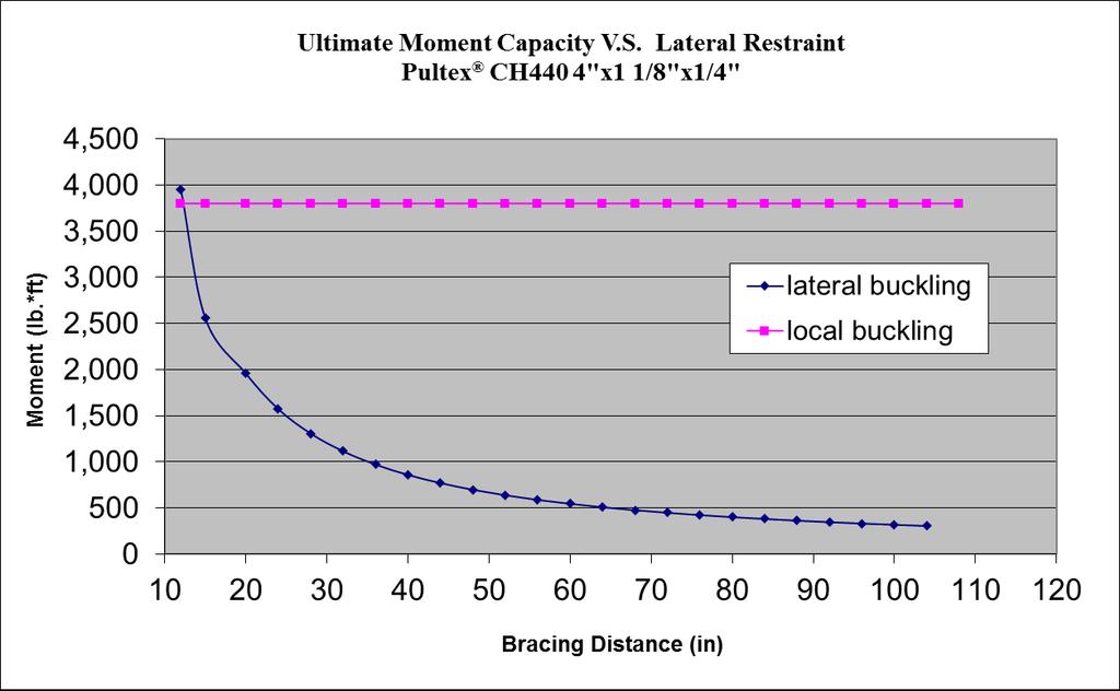
86 The New and Improved Pultex Pultrusion Design Manual Chapter 4 47 The New and Improved Pultex Pultrusion Design Manual Chapter 4 47
87 48 Pultex Standard Structural Profiles Channels 5" x 1-3/8" x 1/4" (Part # CH 540) Ultimate In-Plane Shear Stress (psi) 7, /1525/1625 Series Ultimate Flexural Stress (psi) 33,000 Ex =2.8x10 6 psi Ey =1.0x10 6 psi Ultimate Local Flange Buckling Stress (psi) 23,636 Simply Supported beam with Uniform Ix=5.42 in 4 G =5.0x10 5 psi Ultimate Lateral-torsional Buckling Stress Loads at various L/D ratios Aw=1.25 in 2 Sx=2.17 in 3 with Maximum Lateral Support bracing (psi) 24,262 (lbs/ft) Wt.=1.40 lbs/ft Simply Supported Beam with a Uniform Load Load Tables Based on Minimum Lateral Support L/D ratio Load Tables Based on Laterally Supported Beams Unless Noted Allowable load, In-plane shear parallel to the web, capacity, 3x safety factor (lbs/ft) Allowable load based on the beam flexural capacity, 2.5x safety factor (lbs/ft) Allowable load, local compression buckling capacity of flange, 2.5x safety factor (lbs/ft) Allowable load without lateral support 2.5x safety factor (lbs/ft) Maximum lateral support spacing (inches) Number of lateral restraints per total span (Including Ends) Span (feet) **** **** **** **** **** **** **** **** Note: Bold numbers in the Factored Load Tables represent the governing load Reduction for weight of profile has not been applied to the charts The New and Improved Pultex Pultrusion Design Manual Chapter 4 48 The New and Improved Pultex Pultrusion Design Manual Chapter 4
88 The New and Improved Pultex Pultrusion Design Manual Chapter 4 49 The New and Improved Pultex Pultrusion Design Manual Chapter 4 49
89 50 Pultex Standard Structural Profiles Channels 6" x 1-5/8" x 1/4" (Part # CH 640) Ultimate In-Plane Shear Stress (psi) 7, /1525/1625 Series Ultimate Flexural Stress (psi) 33,000 Ex =2.8x10 6 psi Ey =1.0x10 6 psi Ultimate Local Flange Buckling Stress (psi) 17,228 Simply Supported beam with Uniform Ix=9.62 in 4 G =5.0x10 5 psi Ultimate Lateral-torsional Buckling Stress Loads at various L/D ratios Aw=1.50 in 2 Sx=3.20 in 3 with Maximum Lateral Support bracing (psi) 17,344 (lbs/ft) Wt.=1.75 lbs/ft Simply Supported Beam with a Uniform Load Load Tables Based on Minimum Lateral Support L/D ratio Load Tables Based on Laterally Supported Beams Unless Noted Allowable load, In-plane shear parallel to the web, capacity, 3x safety factor (lbs/ft) Allowable load based on the beam flexural capacity, 2.5x safety factor (lbs/ft) Allowable load, local compression buckling capacity of flange, 2.5x safety factor (lbs/ft) Allowable load without lateral support 2.5x safety factor (lbs/ft) Maximum lateral support spacing (inches) Number of lateral restraints per total span (Including Ends) Span (feet) **** **** **** **** **** **** **** **** **** **** **** **** **** **** **** **** **** **** Note: Bold numbers in the Factored Load Tables represent the governing load Reduction for weight of profile has not been applied to the charts The New and Improved Pultex Pultrusion Design Manual Chapter 4 50 The New and Improved Pultex Pultrusion Design Manual Chapter 4
90 The New and Improved Pultex Pultrusion Design Manual Chapter 4 51 The New and Improved Pultex Pultrusion Design Manual Chapter 4 51
91 52 Pultex Standard Structural Profiles Channels 6" x 1-11/16" x 3/8" (Part # CH 662) Ultimate In-Plane Shear Stress (psi) 7, /1525/1625 Series Ultimate Flexural Stress (psi) 33,000 Ex =2.8x10 6 psi Ey =1.0x10 6 psi Ultimate Local Flange Buckling Stress (psi) 34,272 Simply Supported beam with Uniform Ix=13.42 in 4 G =5.0x10 5 psi Ultimate Lateral-torsional Buckling Stress Loads at various L/D ratios Aw=2.25 in 2 Sx=4.47 in 3 with Maximum Lateral Support bracing (psi) 38,167 (lbs/ft) Wt.=2.61 lbs/ft Simply Supported Beam with a Uniform Load Load Tables Based on Minimum Lateral Support L/D ratio Load Tables Based on Laterally Supported Beams Unless Noted Allowable load, In-plane shear parallel to the web, capacity, 3x safety factor (lbs/ft) Allowable load based on the beam flexural capacity, 2.5x safety factor (lbs/ft) Allowable load, local compression buckling capacity of flange, 2.5x safety factor (lbs/ft) Allowable load without lateral support 2.5x safety factor (lbs/ft) Maximum lateral support spacing (inches) Number of lateral restraints per total span (Including Ends) Span (feet) The New and Improved Pultex Pultrusion Design Manual Chapter **** **** **** **** **** **** **** Note: Bold numbers in the Factored Load Tables represent the governing load Reduction for weight of profile has not been applied to the charts 52 The New and Improved Pultex Pultrusion Design Manual Chapter 4
92 The New and Improved Pultex Pultrusion Design Manual Chapter 4 53 The New and Improved Pultex Pultrusion Design Manual Chapter 4 53
93 Pultex Standard Structural Profiles Channels 54 7" x 2" x 1/4" (Part # CH 740) Ultimate In-Plane Shear Stress (psi) 7, /1525/1625 Series Ultimate Flexural Stress (psi) 33,000 Ex =2.8x10 6 psi Ey =1.0x10 6 psi Ultimate Local Flange Buckling Stress (psi) 10,616 Simply Supported beam with Uniform Ix=16.42 in 4 G =5.0x10 5 psi Ultimate Lateral-torsional Buckling Stress Loads at various L/D ratios Aw=1.75 in 2 Sx=4.69 in 3 with Maximum Lateral Support bracing (psi) 11,525 (lbs/ft) Wt.=2.03 lbs/ft Simply Supported Beam with a Uniform Load Load Tables Based on Minimum Lateral Support L/D ratio Load Tables Based on Laterally Supported Beams Unless Noted Allowable load, In-plane shear parallel to the web, capacity, 3x safety factor (lbs/ft) Allowable load based on the beam flexural capacity, 2.5x safety factor (lbs/ft) Allowable load, local compression buckling capacity of flange, 2.5x safety factor (lbs/ft) Allowable load without lateral support 2.5x safety factor (lbs/ft) Maximum lateral support spacing (inches) Number of lateral restraints per total span (Including Ends) Span (feet) The New and Improved Pultex Pultrusion Design Manual Chapter **** **** **** **** **** **** **** **** **** **** **** **** **** **** **** **** **** **** **** **** **** **** **** **** **** **** **** **** **** Note: Bold numbers in the Factored Load Tables represent the governing load Reduction for weight of profile has not been applied to the charts 54 The New and Improved Pultex Pultrusion Design Manual Chapter 4
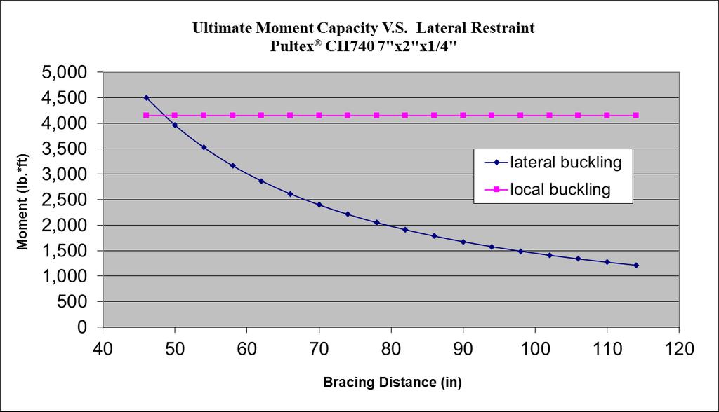
94 The New and Improved Pultex Pultrusion Design Manual Chapter 4 55 The New and Improved Pultex Pultrusion Design Manual Chapter 4 55
95 56 Pultex Standard Structural Profiles Channels 14 x 6 x 1/2" (Part # CH 802) Ultimate In-Plane Shear Stress (psi) 7, /1525/1625 Series Ultimate Flexural Stress (psi) 33,000 Ex =4.0x10 6 psi Ey =1.5x10 6 psi Ultimate Local Flange Buckling Stress (psi) 6,506 Simply Supported beam with Uniform Ix= in 4 G =5.0x10 5 psi Ultimate Lateral-torsional Buckling Stress Loads at various L/D ratios Aw=7.0 in 2 Sx=49.87 in 3 with Maximum Lateral Support bracing (psi) 6,643 (lbs/ft) Wt.=10.41 lbs/ft Simply Supported Beam with a Uniform Load Span (feet) Number of lateral restraints per total span (Including Ends) Maximum lateral support spacing (inches) Allowable load without lateral support 2.5x safety factor (lbs/ft) Load Tables Based on Laterally Supported Beams Unless Noted Allowable load, local compression buckling capacity of flange, 2.5x safety factor (lbs/ft) Allowable load based on the beam flexural capacity, 2.5x safety factor (lbs/ft) Load Tables Based on Minimum Lateral Support L/D ratio Allowable load, In-plane shear parallel to the web, capacity, 3x safety factor (lbs/ft) **** **** **** **** **** **** **** **** **** **** **** **** **** **** **** **** **** **** **** **** **** **** **** **** **** **** **** **** **** **** **** **** **** **** **** **** **** **** **** **** **** **** **** **** **** Note: Bold numbers in the Factored Load Tables represent the governing load Reduction for weight of profile has not been applied to the charts The New and Improved Pultex Pultrusion Design Manual Chapter 4 56
96 Pultex Standard Structural Profiles Channels 14 x 6 x 1/2" (Part # CH 802) Ultimate In-Plane Shear Stress (psi) 7, /1525/1625 Series Ultimate Flexural Stress (psi) 33,000 Ex =4.0x10 6 psi Ey =1.5x10 6 psi Ultimate Local Flange Buckling Stress (psi) 6,506 Simply Supported beam with Uniform Ix= in 4 G =5.0x10 5 psi Ultimate Lateral-torsional Buckling Stress Loads at various L/D ratios Aw=7.0 in 2 Sx=49.87 in 3 with Maximum Lateral Support bracing (psi) 6,643 (lbs/ft) Wt.=10.41 lbs/ft Simply Supported Beam with a Uniform Load Span (feet) Number of lateral restraints per total span (Including Ends) Maximum lateral support spacing (inches) Allowable load without lateral support 2.5x safety factor (lbs/ft) Load Tables Based on Laterally Supported Beams Unless Noted Allowable load, local compression buckling capacity of flange, 2.5x safety factor (lbs/ft) Allowable load based on the beam flexural capacity, 2.5x safety factor (lbs/ft) Load Tables Based on Minimum Lateral Support L/D ratio Allowable load, In-plane shear parallel to the web, capacity, 3x safety factor (lbs/ft) **** **** **** **** **** **** **** **** **** **** **** **** **** **** **** **** **** **** **** **** **** **** **** **** **** **** **** **** **** **** **** **** **** **** **** **** **** **** **** **** **** **** **** **** **** **** **** **** **** **** **** Note: Bold numbers in the Factored Load Tables represent the governing load Reduction for weight of profile has not been applied to the charts The New and Improved Pultex Pultrusion Design Manual Chapter
97 58 The New and Improved Pultex Pultrusion Design Manual Chapter 4 58
98 Pultex Standard Structural Profiles Channels 8" x 2-3/16" x 1/4" (Part # CH 840) Ultimate In-Plane Shear Stress (psi) 7, /1525/1625 Series Ultimate Flexural Stress (psi) 33,000 Ex =2.8x10 6 psi Ey =1.0x10 6 psi Ultimate Local Flange Buckling Stress (psi) 9,396 Simply Supported beam with Uniform Ix=24.30 in 4 G =5.0x10 5 psi Ultimate Lateral-torsional Buckling Stress Loads at various L/D ratios Aw=2.0 in 2 Sx=6.07 in 3 with Maximum Lateral Support bracing (psi) 10,158 (lbs/ft) Wt.=2.42 lbs/ft Simply Supported Beam with a Uniform Load Span (feet) Number of lateral restraints per total span (Including Ends) Maximum lateral support spacing (inches) Allowable load without lateral support 2.5x safety factor (lbs/ft) Load Tables Based on Laterally Supported Beams Unless Noted Allowable load, local compression buckling capacity of flange, 2.5x safety factor (lbs/ft) Allowable load based on the beam flexural capacity, 2.5x safety factor (lbs/ft) Load Tables Based on Minimum Lateral Support L/D ratio Allowable load, In-plane shear parallel to the web, capacity, 3x safety factor (lbs/ft) **** **** **** **** **** **** **** **** **** **** **** **** **** **** **** **** **** **** **** **** **** **** **** **** **** **** **** **** **** **** **** **** **** **** **** **** **** **** Note: Bold numbers in the Factored Load Tables represent the governing load Reduction for weight of profile has not been applied to the charts The New and Improved Pultex Pultrusion Design Manual Chapter 4 59 The New and Improved Pultex Pultrusion Design Manual Chapter 4 59
99 60 The New and Improved Pultex Pultrusion Design Manual Chapter 4 The New and Improved Pultex Pultrusion Design Manual Chapter 4
100 Pultex Standard Structural Profiles Channels 8" x 2-3/16" x 3/8" (Part # CH 860) Ultimate In-Plane Shear Stress (psi) 7, /1525/1625 Series Ultimate Flexural Stress (psi) 33,000 Ex =2.8x10 6 psi Ey =1.0x10 6 psi Ultimate Local Flange Buckling Stress (psi) 21,139 Simply Supported beam with Uniform Ix=33.75 in 4 G =5.0x10 5 psi Ultimate Lateral-torsional Buckling Stress Loads at various L/D ratios Aw=3.0 in 2 Sx=8.43 in 3 with Maximum Lateral Support bracing (psi) 12,800 (lbs/ft) Wt.=3.57 lbs/ft Simply Supported Beam with a Uniform Load Span (feet) Number of lateral restraints per total span (Including Ends) Maximum lateral support spacing (inches) Allowable load without lateral support 2.5x safety factor (lbs/ft) Load Tables Based on Laterally Supported Beams Unless Noted Allowable load, local compression buckling capacity of flange, 2.5x safety factor (lbs/ft) Allowable load based on the beam flexural capacity, 2.5x safety factor (lbs/ft) Load Tables Based on Minimum Lateral Support L/D ratio Allowable load, In-plane shear parallel to the web, capacity, 3x safety factor (lbs/ft) **** **** **** **** **** **** **** **** Note: Bold numbers in the Factored Load Tables represent the governing load Reduction for weight of profile has not been applied to the charts The New and Improved Pultex Pultrusion Design Manual Chapter 4 61 The New and Improved Pultex Pultrusion Design Manual Chapter 4 61

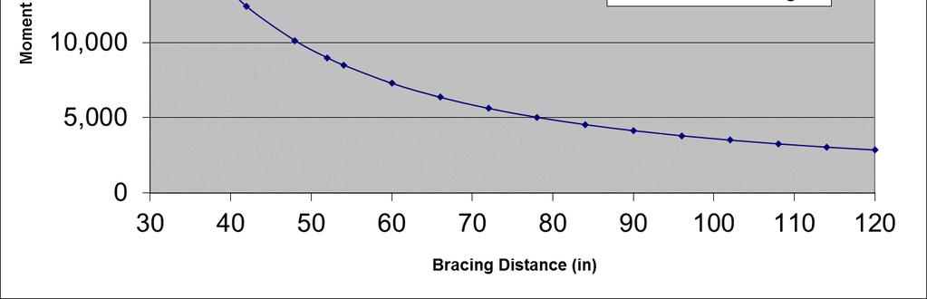
101 62 The New and Improved Pultex Pultrusion Design Manual Chapter 4 62 The New and Improved Pultex Pultrusion Design Manual Chapter 4
102 Pultex Standard Structural Profiles Channels 11-1/2" x 2-3/4" x 1/2" (Part # CH 995) Ultimate In-Plane Shear Stress (psi) 7, /1525/1625 Series Ultimate Flexural Stress (psi) 33,000 Ex =2.8x10 6 psi Ey =1.0x10 6 psi Ultimate Local Flange Buckling Stress (psi) 27,046 Simply Supported beam with Uniform Ix= in 4 G =5.0x10 5 psi Ultimate Lateral-torsional Buckling Stress Loads at various L/D ratios Aw=5.75 in 2 Sx=21.67 in 3 with Maximum Lateral Support bracing (psi) 30,452 (lbs/ft) Wt.=6.69 lbs/ft Simply Supported Beam with a Uniform Load Span (feet) Number of lateral restraints per total span (Including Ends) Maximum lateral support spacing (inches) Allowable load without lateral support 2.5x safety factor (lbs/ft) Load Tables Based on Laterally Supported Beams Unless Noted Allowable load, local compression buckling capacity of flange, 2.5x safety factor (lbs/ft) Allowable load based on the beam flexural capacity, 2.5x safety factor (lbs/ft) Load Tables Based on Minimum Lateral Support L/D ratio Allowable load, In-plane shear parallel to the web, capacity, 3x safety factor (lbs/ft) **** **** **** **** **** **** **** **** **** Note: Bold numbers in the Factored Load Tables represent the governing load Reduction for weight of profile has not been applied to the charts The New and Improved Pultex Pultrusion Design Manual Chapter 4 63 The New and Improved Pultex Pultrusion Design Manual Chapter 4 63
103 64 The New and Improved Pultex Pultrusion Design Manual Chapter 4 64 The New and Improved Pultex Pultrusion Design Manual Chapter 4
104 Pultex Standard Structural Profiles Channels 10" x 2-3/4" x 1/2" SuperStructural (Part # CH 980) Ultimate In-Plane Shear Stress (psi) 7, /1525/1625 Series Ultimate Flexural Stress (psi) 33,000 Ex =3.5x10 6 psi Ey =1.5x10 6 psi Ultimate Local Flange Buckling Stress (psi) 20,278 Simply Supported beam with Uniform Ix=86.87 in 4 G =5.0x10 5 psi Ultimate Lateral-torsional Buckling Stress Loads at various L/D ratios Aw=5.0 in 2 Sx=17.37 in 3 with Maximum Lateral Support bracing (psi) 21,102 (lbs/ft) Wt.=5.94 lbs/ft Simply Supported Beam with a Uniform Load Span (feet) Number of lateral restraints per total span (Including Ends) Maximum lateral support spacing (inches) Allowable load without lateral support 2.5x safety factor (lbs/ft) Load Tables Based on Laterally Supported Beams Unless Noted Allowable load, local compression buckling capacity of flange, 2.5x safety factor (lbs/ft) Allowable load based on the beam flexural capacity, 2.5x safety factor (lbs/ft) Load Tables Based on Minimum Lateral Support L/D ratio Allowable load, Inplane shear parallel to the web, capacity, 3x safety factor (lbs/ft) **** **** **** **** **** **** **** **** **** **** **** **** **** Note: Bold numbers in the Factored Load Tables represent the governing load Reduction for weight of profile has not been applied to the charts The New and Improved Pultex Pultrusion Design Manual Chapter 4 65 The New and Improved Pultex Pultrusion Design Manual Chapter 4 65
105 66 The New and Improved Pultex Pultrusion Design Manual Chapter 4 66 The New and Improved Pultex Pultrusion Design Manual Chapter 4
106 Pultex Standard Structural Profiles Channels 24" x 4" x 15/32" (Part # CH 994) Ultimate In-Plane Shear Stress (psi) 7, /1525/1625 Series Ultimate Flexural Stress (psi) 33,000 Ex =2.8x10 6 psi Ey =1.0x10 6 psi Ultimate Local Flange Buckling Stress (psi) 14,184 Simply Supported beam with Uniform Ix= in 4 G =5.0x10 5 psi Ultimate Lateral-torsional Buckling Stress Loads at various L/D ratios Aw=11.32 in 2 Sx=82.0 in 3 with Maximum Lateral Support bracing (psi) 14,419 (lbs/ft) Wt.=11.88 lbs/ft Simply Supported Beam with a Uniform Load Span (feet) Number of lateral restraints per total span (Including Ends) Maximum lateral support spacing (inches) Allowable load without lateral support 2.5x safety factor (lbs/ft) Load Tables Based on Laterally Supported Beams Unless Noted Allowable load, local compression buckling capacity of flange, 2.5x safety factor (lbs/ft) Allowable load based on the beam flexural capacity, 2.5x safety factor (lbs/ft) Load Tables Based on Minimum Lateral Support L/D ratio Allowable load, In-plane shear parallel to the web, capacity, 3x safety factor (lbs/ft) **** **** **** **** **** **** **** **** **** **** **** **** **** **** **** **** **** **** **** **** **** **** **** **** **** **** **** **** **** **** **** **** **** **** **** **** **** **** **** **** **** **** **** Note: Bold numbers in the Factored Load Tables represent the governing load Reduction for weight of profile has not been applied to the charts The New and Improved Pultex Pultrusion Design Manual Chapter 4 67 The New and Improved Pultex Pultrusion Design Manual Chapter 4 67
107 68 The New and Improved Pultex Pultrusion Design Manual Chapter 4 The New and Improved Pultex Pultrusion Design Manual Chapter 4 68
108 Pultex Standard Structural Profiles Channels 18" x 2-1/2" x 1/4" (Part # CH 810) Ultimate In-Plane Shear Stress (psi) 7, /1525/1625 Series Ultimate Flexural Stress (psi) 33,000 Ex =2.8x10 6 psi Ey =1.0x10 6 psi Ultimate Local Flange Buckling Stress (psi) 11,064 Simply Supported beam with Uniform Ix= in4 G =5.0x10 5 psi Ultimate Lateral-torsional Buckling Stress Loads at various L/D ratios Aw=4.5 in2 Sx=22.75 in3 with Maximum Lateral Support bracing (psi) 32,750 (lbs/ft) Wt.= 4.86 lbs/ft Simply Supported Beam with a Uniform Load Span (feet) Number of lateral restraints per total span (Including Ends) Maximum lateral support spacing (inches) Allowable load without lateral support 2.5x safety factor (lbs/ft) Load Tables Based on Laterally Supported Beams Unless Noted Allowable load, local compressio n buckling capacity of flange, 2.5x safety factor (lbs/ft) Allowable load based on the beam flexural capacity, 2.5x safety factor (lbs/ft) Load Tables Based on Minimum Lateral Support L/D ratio Allowable load, In-plane shear parallel to the web, capacity, 3x safety factor (lbs/ft) **** **** **** **** **** **** **** **** **** **** **** **** **** **** **** **** **** **** **** **** **** **** **** **** **** **** **** **** **** **** **** **** **** **** **** **** **** **** **** **** **** Note: Bold numbers in the Factored Load Tables represent the governing load Reduction for weight of profile has not been applied to the charts The New and Improved Pultex Pultrusion Design Manual Chapter 4 69 The New and Improved Pultex Pultrusion Design Manual Chapter
109 70 The New and Improved Pultex Pultrusion Design Manual Chapter 4 70 The New and Improved Pultex Pultrusion Design Manual Chapter 4
110 Pultex Standard Structural Profiles Square Tubes 1-1/2" x 1-1/2" x 1/4" (Part # TQ 142) Ultimate In-Plane Shear Strength 7, /1525/1625 Series Ultimate Flexural Strength (psi) 33,000 Simply Supported beam with E = 3.2x10 6 psi G =4.2x10 5 psi Ultimate Local Buckling Strength 126,511 Uniform Loads at various Ix=.33 in 4 Sx= 44 in 3 Simply Supported with a Uniform Load L/D ratios (lbs/ft) Aw=.75 in 2 Wt.= 1.02 lbs/ft Laterally Supported beams L/D ratio Span (feet) Allowable load, local compression buckling capacity, 2.5x Safety Factor (lbs/ft) Allowable load, flexural capacity, 2.5x Safety Factor (lbs/ft) Allowable load, In-plane shear of the web capacity, 3x Safety Factor (lbs/ft) Note: Bold numbers in the Factored Load Tables represent the governing load 1-3/4" x 1-3/4" x 1/8" (Part # TQ 126) Ultimate In-Plane Shear Strength 7, /1525/1625 Series Ultimate Flexural Strength (psi) 33,000 Simply Supported beam with E =3.2x10 6 psi G =4.2x10 5 psi Ultimate Local Buckling Strength 23,237 Uniform Loads at various Ix=.35 in 4 Sx=.40 in 3 Simply Supported with a Uniform Load L/D ratios (lbs/ft) Aw=.438 in 2 Wt.=.56 lbs/ft Laterally Supported beams L/D ratio Span (feet) Allowable load, local compression buckling capacity, 2.5x Safety Factor (lbs/ft) Allowable load, flexural capacity, 2.5x Safety Factor (lbs/ft) Allowable load, In-plane shear of the web capacity, 3x Safety Factor (lbs/ft) Note: Bold numbers in the Factored Load Tables represent the governing load The New and Improved Pultex Pultrusion Design Manual Chapter 4 71
111 Pultex Standard Structurals Square Tubes 1-3/4" x 1-3/4" x 1/4" (Part # TQ 144) Ultimate In-Plane Shear Strength (psi) 7, /1525/1625 Series Ultimate Flexural Strength (psi) 33,000 Simply Supported beam with E =3.2x10 6 psi G =4.2x10 5 psi Ultimate Local Buckling Strength (psi) 92,947 Uniform Loads at various I x =.57 in 4 S x =.67 in 3 Simply Supported with a Uniform Load L/D ratios (lbs/ft) A w =.875 in Wt.=1.12 lbs/ft Laterally Supported beams L/D ratio Allowable load, local compressio n buckling capacity, 2.5x Safety Factor Allowable load, flexural capacity, 2.5x Safety Factor (lbs/ft) Allowable load, Inplane shear of the web capacity, 3x Safety Span (feet) Note: Bold numbers in the Factored Load Tables represent the governing load 2" x 2" x 1/8" (Part # TQ 220) Ultimate In-Plane Shear Strength (psi) 7, /1525/1625 Series Ultimate Flexural Strength (psi) 33,000 Simply Supported beam E =3.2x10 6 psi G =4.2x10 5 psi Ultimate Local Buckling Strength (psi) 17,791 with Uniform Loads at various Ix=.53 in 4 Sx=.53 in 3 Simply Supported with a Uniform Load L/D ratios (lbs/ft) Aw=.5 in 2 Wt.=.73 lbs/ft Laterally Supported beams L/D ratio Allowable load, local compression buckling capacity, 2.5x Safety Factor (lbs/ft) Allowable load, flexural capacity, 2.5x Safety Factor (lbs/ft) Allowable load, In-plane shear of the web capacity, 3x Safety Factor (lbs/ft) Span (feet) Note: Bold numbers in the Factored Load Tables represent the governing load 72 The New and Improved Pultex Pultrusion Design Manual Chapter 4
112 Pultex Standard Structural Profiles Square Tubes 2" x 2" x 1/4" (Part # TQ 240) Ultimate In-Plane Shear Strength (psi) 7, /1525/1625 Series Ultimate Flexural Strength (psi) 33,000 Simply Supported beam E =3.2x10 6 psi G =4.2x10 5 psi Ultimate Local Buckling Strength (psi) 71,162 with Uniform Loads at various Ix=.89 in 4 Sx=.89 in 3 Simply Supported with a Uniform Load L/D ratios (lbs/ft) Aw=1.0 in 2 Wt.=1.50 lbs/ft Laterally Supported beams L/D ratio Span (feet) Allowable load, local compression buckling capacity, 2.5x Safety Factor (lbs/ft) Allowable load, flexural capacity, 2.5x Safety Factor (lbs/ft) Allowable load, In-plane shear of the web capacity, 3x Safety Factor (lbs/ft) Note: Bold numbers in the Factored Load Tables represent the governing load 2.11" x 2.11" x.20" (Part # TQ 230) Ultimate In-Plane Shear Strength (psi) 7, /1525/1625 Series Ultimate Flexural Strength (psi) 33,000 Simply Supported beam with E =3.2x10 6 psi G =4.2x10 5 psi Ultimate Local Buckling Strength (psi) 40,919 Uniform Loads at various Ix=.91 in 4 Sx=.86 in 3 Simply Supported with a Uniform Load L/D ratios (lbs/ft) Aw=.84 in 2 Wt.=1.23 lbs/ft Laterally Supported beams L/D ratio Span (feet) Allowable load, local compression buckling capacity, 2.5x Safety Factor (lbs/ft) Allowable load, flexural capacity, 2.5x Safety Factor (lbs/ft) Allowable load, In-plane shear of the web capacity, 3x Safety Factor (lbs/ft) Note: Bold numbers in the Factored Load Tables represent the governing load The New and Improved Pultex Pultrusion Design Manual Chapter 4 73
113 Pultex Standard Structural Profiles Square Tubes 2-1/2" x 2-1/2" x 1/4" (Part # TQ 242) Ultimate In-Plane Shear Strength (psi) 7, /1525/1625 Series Ultimate Flexural Strength (psi) 33,000 Simply Supported beam with E =3.2x10 6 psi G =4.2x10 5 psi Ultimate Local Buckling Strength (psi) 45,544 Uniform Loads at various Ix= 1.90 in 4 Sx= 1.52 in 3 Simply Supported with a Uniform Load L/D ratios (lbs/ft) Aw=1.25 in 2 Wt.=1.87 lbs/ft Laterally Supported beams L/D ratio Span (feet) Allowable load, local compression buckling capacity, 2.5x Safety Factor (lbs/ft) Allowable load, flexural capacity, 2.5x Safety Factor (lbs/ft) Allowable load, In-plane shear of the web capacity, 3x Safety Factor (lbs/ft) Note: Bold numbers in the Factored Load Tables represent the governing load 2.47 x 2.47 x 0.220" (Part # TQ 247) Ultimate In-Plane Shear Strength (psi) 7, /1525/1625 Series Ultimate Flexural Strength (psi) 33,000 Simply Supported beam with E =3.2x10 6 psi G =4.2x10 5 psi Ultimate Local Buckling Strength (psi) 36,131 Uniform Loads at various Ix= 1.67 in 4 Sx= 1.35 in 3 Simply Supported with a Uniform Load L/D ratios (lbs/ft) Aw=1.09 in 2 Wt.=1.53 lbs/ft Laterally Supported beams L/D ratio Span (feet) Allowable load, local compression buckling capacity, 2.5x Safety Factor (lbs/ft) Allowable load, flexural capacity, 2.5x Safety Factor (lbs/ft) Allowable load, In-plane shear of the web capacity, 3x Safety Factor (lbs/ft) Note: Bold numbers in the Factored Load Tables represent the governing load 74 The New and Improved Pultex Pultrusion Design Manual Chapter 4
114 Pultex Standard Structural Profiles Square Tubes 3" x 3" x 1/4" (Part # TQ 340) Ultimate In-Plane Shear Strength (psi) 7, /1525/1625 Series Ultimate Flexural Strength (psi) 33,000 Simply Supported beam E =3.2x10 6 psi G =4.2x10 5 psi Ultimate Local Buckling Strength (psi) 31,628 with Uniform Loads at various Ix= 3.47 in 4 Sx= 2.31 in 3 Simply Supported with a Uniform Load L/D ratios (lbs/ft) Aw=1.5 in 2 Wt.=2.22 lbs/ft Laterally Supported beams L/D ratio Span (feet) Allowable load, local compression buckling capacity, 2.5x Safety Factor (lbs/ft) Allowable load, flexural capacity, 2.5x Safety Factor (lbs/ft) Allowable load, In-plane shear of the web capacity, 3x Safety Factor (lbs/ft) Note: Bold numbers in the Factored Load Tables represent the governing load The New and Improved Pultex Pultrusion Design Manual Chapter 4 75
115 Pultex Standard Structural Profiles Square Tubes 3-1/2" x 3-1/2" x 3/8" (Part # TQ 360) Ultimate In-Plane Shear Strength (psi) 7, /1525/1625 Series Ultimate Flexural Strength (psi) 33,000 Simply Supported beam with E =3.2x10 6 psi G =4.2x10 5 psi Ultimate Local Buckling Strength (psi) 52,283 Uniform Loads at various Ix= 7.71 in 4 Sx= 4.40 in 3 Simply Supported with a Uniform Load L/D ratios (lbs/ft) Aw=2.62 in 2 Wt.=3.84 lbs/ft Laterally Supported beams L/D ratio Span (feet) Allowable load, local compression buckling capacity, 2.5x Safety Factor (lbs/ft) Allowable load, flexural capacity, 2.5x Safety Factor (lbs/ft) Allowable load, In-plane shear of the web capacity, 3x Safety Factor (lbs/ft) Note: Bold numbers in the Factored Load Tables represent the governing load 76 The New and Improved Pultex Pultrusion Design Manual Chapter 4
116 Pultex Standard Structural Profiles Square Tubes 4" x 4" x 1/4" (Part # TQ 440) Ultimate In-Plane Shear Strength (psi) 7, /1525/1625 Series Ultimate Flexural Strength (psi) 33,000 Simply Supported beam with E =3.2x10 6 psi G =4.2x10 5 psi Ultimate Local Buckling Strength (psi) 17,791 Uniform Loads at various Ix= 8.75 in 4 Sx= 4.37 in 3 Simply Supported with a Uniform Load L/D ratios (lbs/ft) Aw=2.0 in 2 Wt.=3.10 lbs/ft Laterally Supported beams L/D ratio Span (feet) Allowable load, local compression buckling capacity, 2.5x Safety Factor (lbs/ft) Allowable load, flexural capacity, 2.5x Safety Factor (lbs/ft) Allowable load, In-plane shear of the web capacity, 3x Safety Factor (lbs/ft) Note: Bold numbers in the Factored Load Tables represent the governing load The New and Improved Pultex Pultrusion Design Manual Chapter 4 77
117 Pultex Standard Structural Profiles Square Tubes 6" x 6" x 3/8" (Part # TQ 660) Ultimate In-Plane Shear Strength (psi) 7, /1525/1625 Series Ultimate Flexural Strength (psi) 33,000 Simply Supported beam E =3.2x10 6 psi G =4.2x10 5 psi Ultimate Local Buckling Strength 17,791 with Uniform Loads at various Ix= in 4 Sx= in 3 Simply Supported with a Uniform Load L/D ratios (lbs/ft) Aw=4.5 in 2 Wt.=7.58 lbs/ft Laterally Supported beams L/D ratio Span (feet) Allowable load, local compression buckling capacity, 2.5x Safety Factor (lbs/ft) Allowable load, flexural capacity, 2.5x Safety Factor (lbs/ft) Allowable load, In-plane shear of the web capacity, 3x Safety Factor (lbs/ft) Note: Bold numbers in the Factored Load Tables represent the governing load 78 The New and Improved Pultex Pultrusion Design Manual Chapter 4
118 Pultex Standard Structural Profiles Rectangular Tubes 4.40" x 1.43" x 0.13" (Part # TR 420) Ultimate In-Plane Shear Strength (psi) 7, /1525/1625 Series Ultimate Flexural Strength (psi) 33,000 Simply Supported beam E =3.2x10 6 psi G =4.2x10 5 psi Ultimate Local Buckling Strength (psi) 37,249 with Uniform Loads at various Ix=2.89 in 4 Sx=1.31 in 3 Simply Supported with a Uniform Load L/D ratios (lbs/ft) Aw=1.14 in 2 Wt.=1.10 lbs/ft Laterally Supported beams L/D ratio Allowable load, local compression buckling capacity, 2.5x Safety Factor (lbs/ft) Allowable load, flexural capacity, 2.5x Safety Factor (lbs/ft) Allowable load, In-plane shear of the web capacity, 3x Safety Factor (lbs/ft) Span (feet) Note: Bold numbers in the Factored Load Tables represent the governing load 4.74" x 1.72" x 0.125" (Part # TR 422) Ultimate In-Plane Shear Strength (psi) 7, /1525/1625 Series Ultimate Flexural Strength (psi) 33,000 Simply Supported beam with E =3.2x10 6 G =4.2x10 5 psi Ultimate Local Buckling Strength (psi) 23,824 Uniform Loads at various Ix=4.20 in 4 Sx=1.77 in 3 Simply Supported with a Uniform Load L/D ratios (lbs/ft) Aw=1.18 in 2 Wt.=1.36 lbs/ft Laterally Supported beams L/D ratio Span (feet) Allowable load, local compression buckling capacity, 2.5x Safety Factor (lbs/ft) Allowable load, flexural capacity, 2.5x Safety Factor (lbs/ft) Allowable load, In-plane shear of the web capacity, 3x Safety Factor (lbs/ft) Note: Bold numbers in the Factored Load Tables represent the governing load The New and Improved Pultex Pultrusion Design Manual Chapter 4 79
119 Pultex Standard Structural Profiles Rectangular Tubes 5.07" x 2" x 0.132" (Part # TR 522) Ultimate In-Plane Shear Strength (psi) 7, /1525/1625 Series Ultimate Flexural Strength (psi) 33,000 Simply Supported beam with E =3.2x10 6 psi G =4.2x10 5 psi Ultimate Local Buckling Strength (psi) 19,663 Uniform Loads at various Ix=5.65 in 4 Sx=2.23 in 3 Simply Supported with a Uniform Load L/D ratios (lbs/ft) Aw=1.34 in 2 Wt.=1.53 lbs/ft Laterally Supported beams L/D ratio Span (feet) Allowable load, local compression buckling capacity, 2.5x Safety Factor (lbs/ft) Allowable load, flexural capacity, 2.5x Safety Factor (lbs/ft) Allowable load, In-plane shear of the web capacity, 3x Safety Factor (lbs/ft) Note: Bold numbers in the Factored Load Tables represent the governing load 80 The New and Improved Pultex Pultrusion Design Manual Chapter 4
120 Pultex Standard Structural Profiles Rectangular Tubes 6" x 2" x 0.135" Multicell (Part # TR 620) Ultimate In-Plane Shear Strength (psi) 7, /1525/1625 Series Ultimate Flexural Strength (psi) 33,000 Simply Supported beam with E =3.2x10 6 G =4.2x10 5 psi Ultimate Local Buckling Strength (psi) 20,540 Uniform Loads at various Ix=9.34 in 4 Sx=3.11 in 3 Simply Supported with a Uniform Load L/D ratios (lbs/ft) Aw=1.62 in 2 Wt.=1.92 lbs/ft Laterally Supported beams L/D ratio Span (feet) Allowable load, local compression buckling capacity, 2.5x Safety Factor (lbs/ft) Allowable load, flexural capacity, 2.5x Safety Factor (lbs/ft) Allowable load, In-plane shear of the web capacity, 3x Safety Factor (lbs/ft) Note: Bold numbers in the Factored Load Tables represent the governing load The New and Improved Pultex Pultrusion Design Manual Chapter 4 81
121 Pultex Standard Structural Profiles Rectangular Tubes 2" x 6" x 0.135" Multicell (Part # TR 620) Ultimate In-Plane Shear Strength (psi) 7, /1525/1625 Series Ultimate Flexural Strength (psi) 33,000 Simply Supported beam with E =3.2x10 6 psi G =4.2x10 5 psi Ultimate Local Buckling Strength (psi) 20,751 Uniform Loads at various Ix=1.61 in 4 Sx=1.61 in 3 Simply Supported with a Uniform Load L/D ratios (lbs/ft) Aw=.88 in 2 Wt.=1.92 lbs/ft Laterally Supported beams L/D ratio Span (feet) Allowable load, local compression buckling capacity, 2.5x Safety Factor (lbs/ft) Allowable load, flexural capacity, 2.5x Safety Factor (lbs/ft) Allowable load, In-plane shear of the web capacity, 3x Safety Factor (lbs/ft) Note: Bold numbers in the Factored Load Tables represent the governing load 82 The New and Improved Pultex Pultrusion Design Manual Chapter 4
122 Pultex Standard Structural Profiles Rectangular Tubes 6" x 4" x 1/4" (Part # TR 640) Ultimate In-Plane Shear Strength (psi) 7, /1525/1625 Series Ultimate Flexural Strength (psi) 33,000 Simply Supported beam with Uniform E =3.2x10 6 psi G =4.2x10 5 psi Ultimate Local Buckling Strength (psi) 17,753 Loads at various L/D ratios Ix=22.31 in 4 Sx=7.44 in 3 Simply Supported with a Uniform Load (lbs/ft) Aw=3.0 in 2 Wt.=3.87 lbs/ft Laterally Supported beams L/D ratio Span (feet) Allowable load, local compression buckling capacity, 2.5x Safety Factor (lbs/ft) Allowable load, flexural capacity, 2.5x Safety Factor (lbs/ft) Allowable load, Inplane shear of the web capacity, 3x Safety Factor (lbs/ft) Note: Bold numbers in the Factored Load Tables represent the governing load The New and Improved Pultex Pultrusion Design Manual Chapter 4 83
123 Pultex Standard Structural Profiles Rectangular Tubes 7" x 4" x 1/4 " (Part # TR 740) Ultimate In-Plane Shear Strength (psi) 7, /1525/1625 Series Ultimate Flexural Strength (psi) 33,000 Simply Supported beam with Uniform E =3.2x10 6 psi G =4.2x10 5 psi Ultimate Local Buckling Strength (psi) 17,702 Loads at various L/D ratios Ix=33.61 in 4 Sx=9.61 in 3 Simply Supported with a Uniform Load (lbs/ft) Aw=3.5 in 2 Wt.=4.09 lbs/ft Laterally Supported beams L/D ratio Span (feet) Allowable load, local compression buckling capacity, 2.5x Safety Factor (lbs/ft) Allowable load, flexural capacity, 2.5x Safety Factor (lbs/ft) Allowable load, In-plane shear of the web capacity, 3x Safety Factor (lbs/ft) Note: Bold numbers in the Factored Load Tables represent the governing load 84 The New and Improved Pultex Pultrusion Design Manual Chapter 4
124 Pultex Standard Structural Profiles Rectangular Tubes 7" x 4" x 3/8" (Part # TR 760) Ultimate In-Plane Shear Strength (psi) 7, /1525/1625 Series Ultimate Flexural Strength (psi) 33,000 Simply Supported beam with Uniform E =3.2x10 6 psi G =4.2x10 5 psi Ultimate Local Buckling Strength (psi) 39,830 Loads at various L/D ratios Ix=47.58 in 4 Sx=13.60 in 3 Simply Supported with a Uniform Load (lbs/ft) Aw=5.25 in 2 Wt.=6.21 lbs/ft Laterally Supported beams L/D ratio Span (feet) Allowable load, local compression buckling capacity, 2.5x Safety Factor (lbs/ft) Allowable load, flexural capacity, 2.5x Safety Factor (lbs/ft) Allowable load, In-plane shear of the web capacity, 3x Safety Factor (lbs/ft) Note: Bold numbers in the Factored Load Tables represent the governing load The New and Improved Pultex Pultrusion Design Manual Chapter 4 85
125 Pultex Standard Structural Profiles Rectangular Tubes 8" x 1" x0.125" (Part # TR 815) Ultimate In-Plane Shear Strength (psi) 7, /1525/1625 Series Ultimate Flexural Strength (psi) 33,000 Simply Supported beam with Uniform E =2.5x10 6 psi G =4.2x10 5 psi Ultimate Local Buckling Strength (psi) 9,504 Loads at various L/D ratios Ix=0.41 in 4 Sx=0.81 in 3 Simply Supported with a Uniform Load (lbs/ft) Aw=0.58 in 2 Wt.=1.88 lbs/ft Laterally Supported beams L/D ratio Span (feet) Allowable load, local compression buckling capacity, 2.5x Safety Factor (lbs/ft) Allowable load, flexural capacity, 2.5x Safety Factor (lbs/ft) Allowable load, In-plane shear of the web capacity, 3x Safety Factor (lbs/ft) Note: Bold numbers in the Factored Load Tables represent the governing load 86 The New and Improved Pultex Pultrusion Design Manual Chapter 4
126 Pultex Standard Structural Profiles Rectangular Tubes 8" x 4" x 1/4" (Part # TR 842) Ultimate In-Plane Shear Strength (psi) 7, /1525/1625 Series Ultimate Flexural Strength (psi) 33,000 Simply Supported beam with Uniform E =3.2x10 6 psi G =4.2x10 5 psi Ultimate Local Buckling Strength (psi) 17,673 Loads at various L/D ratios Ix=46.80 in 4 Sx=11.70 in 3 Simply Supported with a Uniform Load (lbs/ft) Aw=4.0 in 2 Wt.=4.70 lbs/ft Laterally Supported beams L/D ratio Span (feet) Allowable load, local compression buckling capacity, 2.5x Safety Factor (lbs/ft) Allowable load, flexural capacity, 2.5x Safety Factor (lbs/ft) Allowable load, In-plane shear of the web capacity, 3x Safety Factor (lbs/ft) Note: Bold numbers in the Factored Load Tables represent the governing load The New and Improved Pultex Pultrusion Design Manual Chapter 4 87
127 Pultex Standard Structural Profiles Rectangular Tubes 8" x 4" x 3/8" (Part # TR 860) Ultimate In-Plane Shear Strength (psi) 7, /1525/1625 Series Ultimate Flexural Strength (psi) 33,000 Simply Supported beam with Uniform E =3.2x10 6 psi G =4.2x10 5 psi Ultimate Local Buckling Strength (psi) 39,764 Loads at various L/D ratios Ix=66.63 in 4 Sx=16.66 in 3 Simply Supported with a Uniform Load (lbs/ft) Aw=6.0 in 2 Wt.=6.71 lbs/ft Laterally Supported beams L/D ratio Span (feet) Allowable load, local compression buckling capacity, 2.5x Safety Factor (lbs/ft) Allowable load, flexural capacity, 2.5x Safety Factor (lbs/ft) Allowable load, In-plane shear of the web capacity, 3x Safety Factor (lbs/ft) Note: Bold numbers in the Factored Load Tables represent the governing load 88 The New and Improved Pultex Pultrusion Design Manual Chapter 4
128 E = 2.0x 10 6 psi Weight = 1.18 lb/ft 2 1/8" (Part # FS 020) All Allowable Uniform Loads are in lbs./ft 2. Pultex 1500/1525 & 1625 Series Sheet Spanning in Lengthwise Direction span L/D (inches) E =.8x 10 6 psi Weight = 1.18 lb/ft 2 1/8" (Part # FS020) All Allowable Uniform Loads are in lbs./ft 2. Pultex 1500/1525 & 1625 Series span Pultex Standard Structural Profiles Flat Sheets Sheet Spanning in Crosswise Direction L/D (inches) Pultex Standard Structural Profiles Flat Sheets E = 2.0x 10 6 psi Weight = 2.30 lb/ft 2 1/4" (Part # FS 040) All Allowable Uniform Loads are in lbs./ft 2. Pultex 1500/1525 & 1625 Series Sheet Spanning in Lengthwise Direction span L/D (inches) E =.8x 10 6 psi Weight = 2.30 lb/ft 2 1/4" (Part # FS 040) All Allowable Uniform Loads are in lbs./ft 2. Pultex 1500/1525 & 1625 Series Sheet Spanning in Crosswise Direction span L/D (inches) The New and Improved Pultex Pultrusion Design Manual Chapter 4 89
129 Pultex Standard Structural Profiles Flat Sheets E = 2.0x 10 6 psi Weight = 3.47 lb/ft 2 3/8" (Part # FS 060) All Allowable Uniform Loads are in lbs./ft 2. Pultex 1500/1525 & 1625 Series Sheet Spanning in Lengthwise Direction span L/D (inches) E =.8x 10 6 psi Weight = 3.47 lb/ft 2 3/8" (Part # FS 060) All Allowable Uniform Loads are in lbs./ft 2. Pultex 1500/1525 & 1625 Series span Sheet Spanning in Crosswise Direction L/D (inches) The New and Improved Pultex Pultrusion Design Manual Chapter 4
130 E = 2.0x 10 6 psi Weight = 4.77 lb/ft 2 1/2" (Part # FS 080) All Allowable Uniform Loads are in lbs./ft 2. Pultex 1500/1525 & 1625 Series Sheet Spanning in Lengthwise Direction span L/D (inches) E =.8x 10 6 psi Weight = 4.77 lb/ft 2 1/2" (Part # FS 080) All Allowable Uniform Loads are in lbs./ft 2. Pultex 1500/1525 & 1625 Series span Pultex Standard Structural Profiles Flat Sheets Sheet Spanning in Crosswise Direction L/D (inches) The New and Improved Pultex Pultrusion Design Manual Chapter 4 91
131 E = 2.0x 10 6 psi Weight = 5.77 lb/ft 2 5/8" (Part # FS 090) All Allowable Uniform Loads are in lbs./ft 2. Pultex 1500/1525 & 1625 Series Sheet Spanning in Lengthwise Direction span (inches) E =.8x 10 6 psi Weight = 5.77 lb/ft 2 5/8" (Part # FS 090) All Allowable Uniform Loads are in lbs./ft 2. Pultex 1500/1525 & 1625 Series span Pultex Standard Structural Profiles Flat Sheets L/D Sheet Spanning in Crosswise Direction (inches) L/D 92 The New and Improved Pultex Pultrusion Design Manual Chapter 4
132 E = 2.0x 10 6 psi Weight = 7.49 lb/ft 2 3/4"(Part # FS 100) All Allowable Uniform Loads are in lbs./ft 2. Pultex 1500/1525 & 1625 Series Sheet Spanning in Lengthwise Direction span L/D (inches) E =.8x 10 6 psi Weight = 7.49 lb/ft 2 3/4" (Part # FS 100) All Allowable Uniform Loads are in lbs./ft 2. Pultex 1500/1525 & 1625 Series span Pultex Standard Structural Profiles Flat Sheets Sheet Spanning in Crosswise Direction L/D (inches) The New and Improved Pultex Pultrusion Design Manual Chapter 4 93
133 E = 2.0x 10 6 psi Weight = 9.46 lb/ft 2 1" (Part # FS 110) All Allowable Uniform Loads are in lbs./ft 2. Pultex 1500/1525 & 1625 Series Sheet Spanning in Lengthwise Direction span L/D (inches) E =.8x 10 6 psi Weight = 9.46 lb/ft 2 1" (Part # FS 110) All Allowable Uniform Loads are in lbs./ft 2. Pultex 1500/1525 & 1625 Series span Pultex Standard Structural Profiles Flat Sheets Sheet Spanning in Crosswise Direction L/D (inches) The New and Improved Pultex Pultrusion Design Manual Chapter 4
134 Clip Connection Load Tables with Pultex SuperStructural Angles The following Clip Connection Load Tables were developed based on full section testing of the Pultex SuperStructural angles. The experimental procedure can be located in Appendix A. The load tables were developed based on the following: 1. Experimental test results 2. Room temperature (73) 3. A safety factor has not been applied. All loads are ultimate unless noted. 4. An ultimate bearing strength of 33,000 psi 5. A 4% hole deformation bearing stress of 12,000 psi 6. No damage to the composite materials 7. No chemical exposure 8. Bolted connection only; no adhesive. 9. Full section shear strength through angle heel = 3,400 psi (1500/1525 Series); 3,900 psi (1625 Series) Note: Clip angle connection dimensions are governed by internal dimensions of beams and external dimensions of the flanges on the columns. 1500/1525 Series Pultex SuperStructural Angles Clip Angle Angle Thickness Connection (in) Length (in) Bolt Hole Dia. (in) Bolt Dia. (in) # of Angles in Connection # of Bolts in Shear # of Bolts through Beam Web # of Bolts Connected to Column Ultimate Shear Load through Angle Heels (lbs.) Ultimate Bearing Load of Connection (lbs.) Allowable Bearing Load for 4% Hole Deformation (lbs.) Clip Angle Ultimate Load before Failure (lbs.) 3/8 4 1/2 9/16 1/ ,475 24,750 9,000 11,475 3/8 4 1/2 11/16 5/ ,475 30,938 11,250 11,475 1/2 4 1/2 9/16 1/ ,300 33,000 12,000 15,300 1/2 4 1/2 11/16 5/ ,300 41,250 15,000 15, /1525 Series Pultex SuperStructural Angles Clip Angle Thickness (in) Angle Connection Length (in) Bolt Hole Dia. (in) Bolt Dia. (in) # of Angles in Connection # of Bolts in Shear # of Bolts through Beam Web # of Bolts Connected to Column Ultimate Shear Load through Angle Heels (lbs.) Ultimate Bearing Load of Connection (lbs.) Allowable Bearing Load for 4% Hole Deformation (lbs.) Clip Angle Ultimate Load before Failure (lbs.) 3/8 6 9/16 1/ ,300 24,750 9,000 15,300 3/8 6 11/16 5/ ,300 30,938 11,250 15,300 1/2 6 9/16 1/ ,400 33,000 12,000 20,400 1/2 6 11/16 5/ ,400 41,250 15,000 20,400 The New and Improved Pultex Pultrusion Design Manual Chapter 4 95
135 1500/1525 Series Pultex SuperStructural Angles Clip Angle Thickness (in) Angle Connection Length (in) Bolt Hole Dia. (in) Bolt Dia. (in) # of Angles in Connection # of Bolts in Shear # of Bolts through Beam Web # of Bolts Connected to Column Ultimate Shear Load through Angle Heels (lbs.) Ultimate Bearing Load of Connection (lbs.) Allowable Bearing Load for 4% Hole Deformation (lbs.) Clip Angle Ultimate Load before Failure (lbs.) 3/8 8 1/4 9/16 1/ ,038 37,125 13,500 21,038 3/8 8 1/4 11/16 5/ ,038 46,406 16,875 21,038 1/2 8 1/4 9/16 1/ ,050 49,500 18,000 28,050 1/2 8 1/4 11/16 5/ ,050 61,875 22,500 28, Series Pultex SuperStructural Angles Clip Angle Thickness (in) Angle Connection Length (in) Bolt Hole Dia. (in) Bolt Dia. (in) # of Angles in Connection # of Bolts in Shear # of Bolts through Beam Web # of Bolts Connected to Column Ultimate Shear Load through Angle Heels (lbs.) Ultimate Bearing Load of Connection (lbs.) Allowable Bearing Load for 4%Hole Deformation (lbs.) Clip Angle Ultimate Load before Failure (lbs.) 3/8 4 1/2 9/16 1/ ,163 24,750 9,000 13,163 3/8 4 1/2 11/16 5/ ,163 30,938 11,250 13,163 1/2 4 1/2 9/16 1/ ,550 33,000 12,000 17,550 1/2 4 1/2 11/16 5/ ,550 41,250 15,000 17, The New and Improved Pultex Pultrusion Design Manual Chapter 4
136 1625 Series Pultex SuperStructural Angles Clip Angle Thickness (in) Angle Connection Length (in) Bolt Hole Dia. (in) Bolt Dia. (in) # of Angles in Connection # of Bolts in Shear # of Bolts through Beam Web # of Bolts Connected to Column Ultimate Shear Load through Angle Heels (lbs.) Ultimate Bearing Load of Connection (lbs.) Allowable Bearing Load for 4% Hole Deformation (lbs.) Clip Angle Ultimate Load before Failure (lbs.) 3/8 6 9/16 1/ ,550 24,750 9,000 17,550 3/8 6 11/16 5/ ,550 30,938 11,250 17,550 1/2 6 9/16 1/ ,400 33,000 12,000 23,400 1/2 6 11/16 5/ ,400 41,250 15,000 23, Series Pultex SuperStructural Angles Clip Angle Thickness (in) Angle Connection Length (in) Bolt Hole Dia. (in) Bolt Dia. (in) # of Angles in Connection # of Bolts in Shear # of Bolts through Beam Web # of Bolts Connected to Column Ultimate Shear Load through Angle Heels (lbs.) Ultimate Bearing Load of Connection (lbs.) Allowable Bearing Load for 4% Hole Deformation (lbs.) Clip Angle Ultimate Load before Failure (lbs.) 3/8 8 1/4 9/16 1/ ,131 37,125 13,500 24,131 3/8 8 1/4 11/16 5/ ,131 46,406 16,875 24,131 1/2 8 1/4 9/16 1/ ,175 49,500 18,000 32,175 1/2 8 1/4 11/16 5/ ,175 61,875 22,500 32,175 Note: The maximum slip of the connection at failure is approximately 0.35"without adhesive. The maximum slip of the connection at failure is approximately 0.101" with adhesive. The adhesive does not affect the ultimate load capacity of the connection, but does affect the amount of slip of the connection. The New and Improved Pultex Pultrusion Design Manual Chapter 4 97
137 Member Thickness (inches) Bolt Hole Bearing Capacity of Pultex SuperStructural Beams and Columns Tables 4-3 and 4-4 represent the bearing capacity of the flange and web sections of various beams and columns. The load table is based on the following: 1. The ultimate lengthwise bearing strength of the flange sections is 33,000 psi. 2. The ultimate crosswise bearing strength of the web section is 30,000 psi. 3. The 4% hole deformation longitudinal bearing strength of the flange is 12,000 psi. 4. The 4% hole deformation transverse bearing strength of the web is 11,000 psi. 5. No safety factors are applied. 6. Testing performed at room temperature (73F) 7. No adhesive is used. 8. Bolt torque is not considered. Table 4-3 Bolt Hole Bearing Capacity of Pultex SuperStructural Columns and Beams for 1500/1525 Series Design Chart Bolt Diameter (inches) # of Bolts in Column # of Bolts in Beam 4% Hole Deformation Beam Web Bearing Load in Transverse Direction (lbs.) Ultimate Beam Web Bearing Load in Transverse Direction (lbs.) 4% Hole Deformation Column Flange Bearing Load in Longitudinal Direction (lbs.) Ultimate Column Flange Bearing Load in Longitudinal Direction (lbs.) 1/4 1/ ,563 3,000 8,250 1/4 1/ ,875 5,125 6,000 16,500 1/4 1/ ,813 7,688 9,000 24,750 3/8 1/ ,063 5,625 4,500 12,375 3/8 1/ ,125 11,250 9,000 24,750 3/8 1/ ,188 16,875 13,500 37,125 1/2 1/ ,750 7,500 6,000 16,500 1/2 1/ ,500 15,000 12,000 33,000 1/2 1/ ,250 22,500 18,000 49,500 1/4 5/ ,172 3,203 3,750 10,313 1/4 5/ ,344 6,406 7,500 20,625 1/4 5/ ,516 9,609 11,250 30,938 3/8 5/ ,578 7,031 5,625 15,469 3/8 5/ ,156 14,063 11,250 30,938 3/8 5/ ,734 21,094 16,875 46,406 1/2 5/ ,438 9,375 7,500 20,625 1/2 5/ ,875 18,750 15,000 41,250 1/2 5/ ,313 28,125 22,500 61,875 Note: Values are representative for bolted connections without adhesives. Transverse bearing stress of 1/4" Pultex SuperStructural profiles, Web sections = 20,500 psi., 4% Elongation = 7,500 psi 98 The New and Improved Pultex Pultrusion Design Manual Chapter 4
138 Member Thickness (inches) Bolt Diameter (inches) Table 4-4 Hole Bearing Capacity of Pultex SuperStructural Columns and Beams for 1625 Series Design Chart # of Bolts in Column # of Bolts in Beam 4% Hole Deformation Beam Web Bearing Load in Transverse Direction (lbs.) Ultimate Beam Web Bearing Load in Transverse Direction (lbs.) 4% Hole Deformation Column Flange Bearing Load in Longitudinal Direction (lbs.) Ultimate Column Flange Bearing Load in Longitudinal Direction (lbs.) 1/4 1/ ,175 2,938 3,500 9,500 1/4 1/ ,350 5,875 7,000 19,000 1/4 1/ ,525 8,813 10,500 28,500 3/8 1/ ,372 6,469 5,250 14,250 3/8 1/ ,744 12,938 10,500 28,500 3/8 1/ ,116 19,406 15,750 42,750 1/2 1/ ,163 8,625 7,000 19,000 1/2 1/ ,325 17,250 14,000 38,000 1/2 1/ ,488 25,875 21,000 57,000 1/4 5/ ,469 3,672 4,375 11,875 1/4 5/ ,938 7,344 8,750 23,750 1/4 5/ ,406 11,016 13,125 35,625 3/8 5/ ,965 8,086 6,563 17,813 3/8 5/ ,930 16,172 13,125 35,625 3/8 5/ ,895 24,258 19,688 53,438 1/2 5/ ,953 10,781 8,750 23,750 1/2 5/ ,906 21,563 17,500 47,500 1/2 5/ ,859 32,344 26,250 71,250 Note: Values are representative for bolted connections without adhesives. Transverse bearing stress of 1/4" Pultex SuperStructural profiles 1625 Series, Web sections = 23,500 psi., 4% elongation = 9,400 psi Connection Fastener Edge Distance and Torque Level Recommendations 2 Ratio of distance to fastener diameter Range Edge Distance- End Edge Distance- Side Pitch (Distance between holes) Reference: Structural Plastics Design Manual Recommended Low Torque High Torque ASTM A % of Bolt Proof Load 75% of Bolt Proof Load Bolt Torque Torque Size ft-lbs. (N m) ft-lbs. (N m) 1/2" (39) 57 (77) 5/8" (77) 113 (153) Bolt recommendations based on ASTM A325 grade five coarse threaded bolts Connection testing performed with grade 8 oversized washers (2.5 times hole dia.) Proof strength for ASTM A325 bolt equals 75,000 psi (0.5 GPa) The New and Improved Pultex Pultrusion Design Manual Chapter 4 99
139 Design Example Using the Clip Connection Charts Task Design a connection for a 6" x 6" x 3/8" Wide Flange Section beam that is clipped into a 8" x 8" x 3/8" Wide Flange Section column. (Reference drawing below.) Given Design load on connection is a static load of 6,000 lbs. The corrosive environment requires 1625 Series. Operating temperature = 73F. Minimum Safety Factor = 2.5 Solution: 1. Reference the 1625 Series of Pultex SuperStructural angle clip connection charts for the 4.5" clip angle length (depth of the 6" x 6" x 3/8" section dictates the 4.5" angle length). 2. First, investigate the 3/8" thick angles. Looking across to the Ultimate Load Before Failure Column, the ultimate load of the 3/8" thick clip angle connection is 13,163 lbs. 3. The design load is 6,000 lbs.(2.5 S.F.) = 15,000 lbs.; therefore, the 3/8" section is not adequate. 4. Investigate the 1/2" thick angles. The Ultimate load is 17,550 lbs.; therefore, the 1/2" angle is adequate. 5. Specify the 4" x 4" x 1/2" angle 4.5" long 1625 Series of Pultex SuperStructural angle. 6. Determine the bearing capacity of the two holes in the web of the 6" x 6" x 3/8" Wide Flange Section and the bearing capacity of the four holes in the column. 7. Reference the Hole Bearing Capacity of Pultex Columns and Beams Design Chart. Determine the row that satisfies the desired bolting condition and member sizes. 8. Enter the row for the 3/8" member thickness and two bolts in the beam. The ultimate beam web bearing load in the transverse direction is 16,172 lbs. for the 5/8" diameter bolts. The design load with the 2.5 S.F. is 15,000 lbs.; the connection is adequate. 10. From Table 1a, the column bearing load is adequate at 35,625 lbs. 100 The New and Improved Pultex Pultrusion Design Manual Chapter 4
140 Moment Capacity of Pultex SuperStructural Angles Table M om ent Capacity of 3/8" thick Pultex SuperStructural A ngles 1500/1525/1625 Series Ultim ate M om ent at Failure = 506 in-lbs./in M om ent (in-lbs./in) Moment capacity is in (in-lbs.) per longitudinal inch of angle Table Moment Capacity of 3/8" thick Pultex SuperStructural Angles 1500/1525/1625 Series 1 Ultimate Moment at Failure = 150 in-lbs./in Moment (in-lbs./in) Moment capacity is in (in-lbs.) per longitudinal inch of angle The New and Improved Pultex Pultrusion Design Manual Chapter 4 101
141 Table Moment Capacity of 1/2" thick Pultex SuperStructural Angles 1500/1525/1625 Series Degrees of Rotation 2 1 Ultimate Moment at Failure = 235 in Moment (in-lbs./in) Moment capacity is in (in-lbs.) per longitudinal inch of angle Table Moment Capacity of 1/2" thick Pultex SuperStructural Angles 1500/1525/1625 Series Ultimate M oment at Failure = 954 in-lbs./in M om ent (in-lbs./in) Moment capacity is in (in-lbs.) per longitudinal inch of angle 102 The New and Improved Pultex Pultrusion Design Manual Chapter 4
142 Designing a Connection With a Coped Flange When designing a connection with a coped flange, block shear must be checked to insure that the connection is adequate. The two factors affecting block shear are the transverse tensile and shear strengths of the web section of the beam. Values for transverse tensile strength and in-plane shear strengths can be located in the Material Properties Sheets of Pultex Fiber Reinforced Polymer Structural Profiles and Pultex SuperStructural Profiles for Wide Flange Sections and I-Sections. The procedure for determining the block shear (V block ) allowable load is as follows: Example Coped Flange Connection Figure 4-1 Figure Determine the in-plane shear and tensile strengths of the beam profile with which you are designing. (Material Properties Sheets of Pultex Fiber Reinforced Polymer Structural Profiles and Pultex SuperStructural Profiles for Wide Flange Sections and I-Sections). 2. Determine the shear length (Lv) of the bolted connection. (Reference Figure 4-2) 3. Determine the net tensile length (Lt) of the bolted connection. (Reference Figure 4-2) 4. Apply the proper safety factors to the connection. (Use 2 for demonstration.) Determine if V block allowable is greater than the design load. Design a framed connection using a Pultex SuperStructural 6" x 6" x 3/8" Wide Flange Section coped into an Pultex SuperStructural 8" x 8" x 3/8" beam. The holes are 9/16" to accommodate 1/2" bolts. (Reference Figure 4-1) 1. Referencing the Material Properties Sheets for Pultex SuperStructural Profiles, the in-plane shear and tensile strengths of the web section are 7,000 psi and 10,500 psi, respectively. 2. Calculate the shear length (Lv) of the Figure 1. connection, i.e., ( /16-9/32) = 2.53" 3. Calculate the net tension length (Lt) of the above connection, i.e., (1.5.5(9/16)) =1.219" 4. Apply the proper safety factors to the transverse shear and tensile strengths, i.e., (Allowable shear = 7,000/2 = 3,500 psi) (Allowable tension = 10,500/2 = 5,250 psi) 5. Calculate the allowable shear force for block shear V block i.e., (5000(1.219)(.375) + 3,500(2.53)(.375) = 5,720 lbs. 6. Compare V block allowable to the design load. 3 The New and Improved Pultex Pultrusion Design Manual Chapter 4 103
143 Endnotes 1 Task Committee on Design of the Structural Plastics Research Council of the Technical Council on Research of the American Society of Civil Engineers. Structural Plastics Design Manual Vol. 2. New York: American Society of Civil Engineers, 1984, pg Task Committee on Design of the Structural Plastics Research Council of the Technical Council on Research of the American Society of Civil Engineers. Structural Plastics Design Manual Vol. 1. New York: American Society of Civil Engineers, 1984, pg Bank, L.C. Bolted Connections for Pultruded Frame Structures. Diss. The Catholic University of America, 1996, pg Boresi, A.P. and Schmidt, R.J Advanced Mechanics of Materials. 6 th edition, John Wiley & Sons, Inc. New York, NY. 5 Pandey, M.D., Kabir, M.Z., and Sherbourne, A.N "Flexural-torsional stability of thin-walled composite I-section beams," Composites Engineering, 5(3): Qiao, P.Z, Davalos, J.F., and Wang, J.L "Local buckling of composite FRP shapes by discrete plate analysis," Journal of Structural Engineering, ASCE, 127 (3): Qiao, P.Z. and Zou, G.P Local Buckling of Composite Fiber-Reinforced Plastic Wide-Flange Sections, Journal of Structural Engineering, ASCE, 129(1): Qiao, P.Z. and Zou, G.P. (2002). Local Buckling of Elastically Restrained Fiber- Reinforced Plastic Plates and its Applications to Box-Sections, Journal of Engineering Mechanics, ASCE, 128 (12): Qiao, P.Z Design equations and guidelines for fiber-reinforced polymer (FRP) composite channel sections, Final Report to Creative Pultrusions, Inc., July pages. 104 The New and Improved Pultex Pultrusion Design Manual Chapter 4
144 Chapter 5 Load Tables for Compression Members The objective of Chapter 5 is to provide engineers with a quantifiable baseline for designing with Pultex FRP columns. Creative Pultrusions, through its comprehensive column load test program, provides the most current, thorough manual for the practical design of Pultex FRP columns. Full section column tests were performed by Professor Robert L. Yuan, Ph.D., P.E., at The University of Texas at Arlington, Arlington, Texas. The protocol of full section column tests included more than 300 structural Pultex FRP product specimens: I, W, Round, Square and Angle Sections. The test protocol required the analysis of short, intermediate and long columns, ranging from one to twenty foot section lengths. The tests were conducted in a reaction frame in the vertical position, using pinned-pinned end conditions, with the corresponding effective length coefficient (K) of one. Column design equations, for practical column applications with various end conditions, are available and completely supported by the extensive column load test results. The columns were axially compressed, with measurements taken of the axial deflections and lateral center displacements. Axial load versus lateral displacements were plotted and the ultimate loads determined. The ultimate load is defined as the points on the plots, where the loads no longer increase due to local, global or bearing failure. Creative Pultrusions recognizes that some published results for column load information are inconsistent within the pultrusion industry. The column load tests, conducted by Creative Pultrusions, used true pinned-pinned end conditions with minimum friction effects. The results of this testing protocol correspond to a strong baseline confidence to which engineers can design and provide conclusions. Chapter 5 1
145 Introduction The research work presented in the Load Tables for Compression Members represents a thorough investigation on the behavior of Pultex FRP columns, produced by Creative Pultrusions, to be used as supporting members for civil engineering structures. Five section configurations of Pultex FRP composite columns are studied in the research, as shown in Figure 5-1. Two sections have closed configurations: square tube and round tube; the other three are thinwalled open sections: wide-flange, I, and angle sections. More than 300 column members, with three specimens each, were tested. Figure 5-1 The thicknesses are 1/8" and 1/4" for square tube sections. The dimensions of the square tubes vary from 1.5" to 4". For round tube sections, the thicknesses are 1/8" and 1/4". The diameters of the round tube are 1.5" and 2". For Wide Flange Sections, the thicknesses of flanges and webs are 1/4" and 3/8". The dimension of the Wide Flange Section ranges from 4" to 10". For I-Sections, the thicknesses of flanges and webs are 1/4" and 3/8". The dimensions of I-Sections are 4" x 2" and 8" x 4". For angle sections, the thicknesses of the flanges are 1/4", 3/8" and 1/2". The dimensions of the angle section are 3" x 3", 4" x 4" and 6" x 6". The objectives of the research are to provide: 1. the column load data for five section configurations, taking into consideration the length of the column and the effective length factor, K ; 2. the allowable compressive stresses; 3. the allowable axial compressive loads; 4. software and/or design equations for predicting load capacity of columns with various section configurations; and 5. written explanations to relate experimental data with the design equations and procedures. 2 Chapter 5


146 Pultex FRP Column Test Program The length of the composite column varies from 1' to 20' to include short, intermediate, and long column members. Full scale column tests are performed by an axial compressive load in a vertical position as shown in Figure 5-2. Figure 5-2 MTS Machine Reaction Frame Short vertical column members were tested on a MTS machine; long column members were tested on a 30-ft. reaction frame. During the test, a microprofiler was used to generate the displacement rate of loading at a 0.1 in./min. The measurements included strains, ultimate loads, axial displacements and lateral deflections. The composite materials for the column members are constructed of polyester-based and vinyl ester-based resin matrices, with and without fire retardancy, reinforced with E-glass fibers. Analysis and Discussion Columns with Box Sections (Imperial) For the short columns with box sections, the ultimate load capacity is a function of the bearing strength of the composite material and the column cross-sectional area. In general, the bearing strength of a structural composite is approximately 30 ksi; therefore, the ultimate strength of short columns with box sections depends upon the cross-sectional area; for a given area, the columns with box sections appear to have the highest ultimate load capacities among the columns with other section configurations. For a given wall thickness of a box section, the ultimate load capacity appears to increase linearly with an increase in the section dimensions, e.g., for thickness t = 1/4", length L = 2 ft., the ultimate load strength was 40 kips for 1 3/4" x 1 3/4" box section; 58 kips for 2" x 2" section; and 88 kips for a 3" x 3" section. Chapter 5 3
147 For the long columns, the ultimate column strength is a function of the slenderness ratio KL/r. The column strength decreases with an increase in the slenderness ratio. For columns with box sections, the dividing line at the slenderness ratio for short and long columns appears to be 35. For columns with KL/r less than 35, the bearing strength of the composite controls the ultimate load. For columns with KL/r greater than 35, global buckling strength controls the ultimate load. Columns with Round Sections Similar to the columns with box sections, the ultimate load capacity of the short round column is also a function of the bearing strength of the composites and column cross-sectional area. For a given area and length, the ultimate column strength of a short round column is approximately 20% less than that of a short box column. For the long round columns, the ultimate column strength is a function of the slenderness ratio KL/r. The round column strength decreases with an increase in the slenderness ratio. For round columns, the dividing line at the slenderness ratio appears to be between 30 to 40. For round columns with KL/r greater than 40, the columns have the characterization of an Euler behavior. For round columns with KL/r less than 30, bearing mode of failure dominates the ultimate column strength. At KL/r = 25, the ultimate stress of the round column from test results is less than the bearing strength of 30 ksi of the composites; therefore, the prediction curve in the short round column region becomes an inclined straight line. Columns with Wide Flange Sections From experimental results, the ultimate strength of columns with Wide Flange Sections is about 30 percent of the ultimate strength of columns with box sections for a given cross-sectional dimension and member length. For the long columns, the ultimate column strength is a function of the slenderness ratio KL/r. The column strength decreases with an increase in the slenderness ratio. For columns with Wide Flange Sections, the dividing line at the slenderness ratio for short and long columns appears to be in the range of 40 to 60. For columns with KL/r less than 60, the column ultimate load depends on one-half of the flange width to the flange thickness ratio of b f /2t f. The higher the b f /2t f ratio, the less the ultimate load capacity. Columns with I-Sections Similar to the columns with Wide Flange Sections, the ultimate load capacity of the columns with I-sections is a function of the slenderness ratio KL/r. The column strength decreases with an increase in the slenderness ratio. For columns with I-sections, the dividing line at the slenderness ratio for short and long columns appears to be in the range of 30 to 40. For columns with KL/r greater than 40, the Euler characteristics of the column with I-sections are close to that of the column with Wide Flange Sections; however, for I-section columns with KL/r less than 30, the ultimate stress is significantly higher than the ultimate stress of the Wide Flange Section column due to a smaller b f /t f ratio. The crippling of the flange in the testing of I-section columns was not observed. At KL/r = 30, the ultimate stress of the I-section column from test results is less than the bearing strength of 30 ksi of the composites; therefore, the prediction curve in short I-section column regions becomes an inclined straight line. 4 Chapter 5
148 Columns with Angle Sections Columns with angle sections were axially loaded at the centroid of the section. The ultimate load capacity is a function of the slenderness ratio KL/r. The column strength decreases with an increase in the slenderness ratio. For columns with angle sections, the dividing line at the slenderness ratio for short and long columns appears to be in the range of 45 to 60. For columns with KL/r greater than 60, the Euler characteristics of the column with angle section is close to that of the column with Wide Flange Sections; however, for the angle-section columns with KL/r less than 45, the ultimate stress is significantly lower than that of the Wide Flange Section columns due to a larger b f /t f ratio and localized instability. The crippling of the flange in the testing of angle-section columns was observed for all specimens; the local buckling instigated a torsion and global buckling of the column. In the short angle section column region, the ultimate column strength is sensitive to the b f /t f ratio. For a b f /t f greater than 8, the ultimate strength of the column with angle section decreases significantly. Column Load Design Equations The Column Load Design Equations for E-glass reinforced polymer columns are based on a large group of data points from full section tests of composite columns. The observed column failure can be categorized into two modes: bearing failure and local/global instability. Figure 5-3 depicts a general behavior for all fiber reinforced polymer columns. The curve can be divided into two groups: short column and long column, as the plotted compressive stress versus slenderness ratio. The short columns generally fail in bearing deformation or local buckling mode; the long columns generally fail in the global buckling mode Compressive Stress vs. Slenderness Ratio Figure 5-3 Compressive Stress, ksi Slenderness Ratio, KL/r Chapter 5 5
149 Design Equations for Box Sections For short columns with box sections, a bearing failure due to axial compressive loading governs the design equation as follows: ult Where P ult = Ultimate axial load (lbs.) A = Cross-sectional area (in 2 ) ult = Bearing strength of the composite (psi) Columns with Round- and I-Sections P ult A For short columns with round- and I-sections, the columns fail due to a combination of axial load and bending moment. The design equations consider the interaction of bearing and flexural buckling failure. A linear equation is developed from the test results for the transition behavior as follows: ult 1 KL 30 (ksi) for short Pultex FRP Round Section columns (2) 7 r ult 5 KL 25 (ksi) for short Pultex FRP I Section columns (3) 38 r Where ult = Ultimate compressive stress (ksi) K = Effective length coefficient L = Column length (in) when used in above equation r = Radius of gyration of the section (in) Columns with Wide Flange Sections For short columns with Wide Flange Sections, local buckling or crippling occurs on the flanges. According to the test results, the ultimate local buckling stress, ult,l of the Pultex FRP composite Wide Flange Section column can be predicted by the modified buckling equation of thin plate for isotropic materials as follows: ult 2 E t k 2 12(1 ) b f f 2 (psi) for short Pultex FRP Wide Flange Section columns (4) Where: E = Modulus of elasticity in the loading direction (psi) = Poisson s ratio t f = Thickness of the local flange element (in) b f = Width of the local flange element (in) = 0.8, a coefficient to account for the orthotropic material of the composite k = 0.5 is recommended for the non-stiffened outstanding flanges of the Wide Flange Section k = 4.0 is recommended for the stiffened outstanding webs of the Wide Flange Section 6 Chapter 5
150 It should be noted that the ultimate local buckling strength needs to be checked against bearing strength. The lower value will be used for the ultimate strength of the short composite column with the Wide Flange Section. Then, the ultimate strength of the short column is compared with the flexural buckling strength to determine the dividing point for short and long columns. Columns with Angle Sections For short columns with angle sections, the local buckling of the flange occurs, as in the column with the Wide Flange Section. Thus, the design Equation (4) can also be applied to predict the ultimate strength of the short columns with angle sections. Design Equations for Long Columns The flexural buckling, known as Euler buckling, is the general behavior of long, slender Pultex FRP columns under axial compression loads. According to the test results, the ultimate buckling strength of the composite columns was in agreement with the Euler buckling equation: (psi) ult, Euler for all long Pultex 2 E KL r 2 FRP columns (5) The equation can be applied to the long Pultex FRP composite columns with square-, round-, I-, W-, and angle- sections; however, for columns with angle-sections, flexural-torsional buckling governs the ultimate strength. In the test, the coupling of the flexural and torsional buckling was observed in a form of lateral deflection and global twisting for the angle-section columns. The ultimate flexural-torsional buckling stress can be approximated by the lower value from equation (5) for flexural buckling strength about the weak axis, or from the torsional buckling equation as follows: ult, ft E t f 2(1 ) b f 2 (psi) for short Pultex FRP Angle columns (6) According to the test results, the coefficient = 0.8 is recommended for Equation (6) to account for the orthotropic material of the composite, where b f is the width of the local flange element (in); one-half the width for Wide Flange Sections; whole leg width for angle sections. The effective length coefficient, K-value, in the equation, accounts for the different end conditions. The K-value is recommended in Table 1. for Pultex FRP composite columns with various end supports. Chapter 5 7
151 Table 5-1 Effective Length Coefficient, K-Value End Conditions Recommended K-Value 1. Pinned-Pinned Fixed-Fixed Pinned-Fixed Fixed-Translation Fixed Fixed-Translation Free Pinned-Translation Fixed 2.00 Note: Buckled Shape of Column Displayed by Dashed Line 8 Chapter 5
152 Nomenclature A = Cross-sectional area (in 2 ) b f = Width of local flange element; width of angle leg or ½ width of a Wide Flange Beam (in) E = Modulus of elasticity in the loading direction (psi) Fa = Allowable compressive stress (psi) I x,i y = Moment of Inertia (in 4 ) k = Flange stiffness factor 0.5 for non-stiffened outstanding flanges of the Wide Flange Section; 4.0 for stiffened K = Effective length coefficient L = Length of column (ft); (in) when used in KL/r equation Pa = Allowable axial load (lbs.) r = Radius of gyration of the section (in) S = Section Modulus (in 3 ) t f = Thickness of local flange element (in) = Poisson s Ratio (.36 in/in) = 0.8, a coefficient to account for the orthotrophic material of the composite ult = Ultimate compressive or bearing stress of the composite (psi) ult,l = Ultimate local buckling stress (psi) ult,euler = Ultimate Euler buckling stress (psi) ult,ft = Ultimate flexural-torsional buckling stress (psi) Chapter 5 9
153 Tables for Allowable Compressive Stresses and Loads The following tables provide information for the allowable stresses (Fa) and the allowable loads (Pa) for columns with square tube sections, round sections, Wide Flange Sections, I-sections and angle-sections. The tables represent sections used as compressive members (columns). The tables were developed based on the following criteria: 1. Experimental test results 2. Room temperature (73 F) 3. A safety factor of S.F. = A value of K = A value of E = 3x10 6 psi 6. =.36 in/in 7. No damages on the composite columns 8. Tables display KL/r values to 200 for reference. It is recommended that KL/r be limited to Chapter 5
154 Tables for Allowable Compressive Stresses and Loads Pultex Standard Structural Profiles Equal Leg Angles 2" x 2" x 1/4" (Part# AE 240) Pultex 1500/1525/1625 Series A =.92 in 2, rz =.38 in Allowable Axial Stresses and Loads Effective Column Length (KL) (ft.) KL/r Fa (psi) Pa (lbs.) Short Column Long Column Long Column Long Column Long Column Long Column Long Column Long Column Long Column Long Column Long Column Long Column Long Column Long Column Long Column Chapter 5 11
155 Pultex Standard Structural Profiles Equal Leg Angles 3" x 3" x 1/4" (Part# AE 340) Pultex 1500/1525/1625 Series A = 1.42 in 2, rz =.58 in Allowable Axial Stresses and Loads Effective Column Length (KL) (ft.) KL/r Fa (psi) Pa (lbs.) Short Column Short Column Short Column Short Column Short Column Long Column Long Column Long Column Long Column Long Column Long Column Long Column Long Column Long Column Long Column Long Column Long Column Long Column Long Column 12 Chapter 5
156 Pultex Standard Structural Profiles Equal Leg Angles 3" x 3" x 3/8" (Part# AE 360) Pultex 1500/1525/1625 Series A = 2.1 in 2, rz =.58 in Allowable Axial Stresses and Loads Effective Column Length (KL) (ft.) KL/r Fa (psi) Pa (lbs.) Short Column Short Column Short Column Long Column Long Column Long Column Long Column Long Column Long Column Long Column Long Column Long Column Long Column Long Column Long Column Long Column Long Column Long Column Long Column Long Column Long Column Chapter 5 13
157 Pultex Standard Structural Profiles Equal Leg Angles 4" x 4" x 1/4" (Part# AE 440) Pultex 1500/1525/1625 Series A = 1.92 in 2, rz =.79 in Allowable Axial Stresses and Loads Effective Column Length (KL) (ft.) KL/r Fa (psi) Pa (lbs.) Short Column Short Column Short Column Short Column Short Column Short Column Short Column Short Column Short Column Short Column Short Column Long Column Long Column Long Column Long Column Long Column Long Column Long Column Long Column Long Column Long Column Long Column Long Column 14 Chapter 5
158 Pultex Standard Structural Profiles Equal Leg Angles 4" x 4" x 3/8" (Part# AE 460) Pultex 1500/1525/1625 Series A = 2.84 in 2, rz =.78 in Allowable Axial Stresses and Loads Effective Column Length (KL) (ft.) KL/r Fa (psi) Pa (lbs.) Short Column Short Column Short Column Short Column Short Column Short Column Short Column Long Column Long Column Long Column Long Column Long Column Long Column Long Column Long Column Long Column Long Column Long Column Long Column Long Column Long Column Long Column Long Column Chapter 5 15
159 Pultex Standard Structural Profiles Equal Leg Angles 4" x 4" x 1/2" (Part# AE 480) Pultex 1500/1525/1625 Series A = 3.72 in 2, rz =.78 in Allowable Axial Stresses and Loads Effective Column Length (KL) (ft.) KL/r Fa (psi) Pa (lbs.) Short Column Short Column Short Column Short Column Long Column Long Column Long Column Long Column Long Column Long Column Long Column Long Column Long Column Long Column Long Column Long Column Long Column Long Column Long Column Long Column Long Column Long Column Long Column Long Column Long Column 16 Chapter 5
160 Pultex Standard Structural Profiles Equal Leg Angles 6" x 6" x 3/8" (Part# AE 660) Pultex 1500/1525/1625 Series A = 4.34 in 2, rz = 1.18 in Allowable Axial Stresses and Loads Effective Column Length (KL) (ft.) KL/r Fa (psi) Pa (lbs.) Short Column Short Column Short Column Short Column Short Column Short Column Short Column Short Column Short Column Short Column Short Column Short Column Short Column Short Column Short Column Short Column Short Column Long Column Long Column Long Column Long Column Long Column Long Column Long Column Long Column Long Column Long Column Long Column Long Column Long Column Long Column Long Column Long Column Long Column Long Column Long Column Long Column Long Column Long Column Chapter 5 17
161 Pultex Standard Structural Profiles Equal Leg Angles 6" x 6" x 1/2" (Part# AE 680) Pultex 1500/1525/1625 Series A = 5.72 in 2, rz = 1.18 in Allowable Axial Stresses and Loads Effective Column Length (KL) (ft.) KL/r Fa (psi) Pa (lbs.) Short Column Short Column Short Column Short Column Short Column Short Column Short Column Short Column Short Column Short Column Short Column Short Column Long Column Long Column Long Column Long Column Long Column Long Column Long Column Long Column Long Column Long Column Long Column Long Column Long Column Long Column Long Column Long Column Long Column Long Column Long Column Long Column Long Column Long Column Long Column Long Column Long Column Long Column Long Column 18 Chapter 5
162 2" x 2" x 1/4" (Part# TQ 240) Pultex 1500/1525/1625 Series A = 1.73 in 2, r =.72in Allowable Axial Stresses and Loads Pultex Standard Structural Profiles Square Tubes Effective Column Length (KL) (ft.) KL/r Fa (psi) Pa (lbs.) Short Column Short Column Long Column Long Column Long Column Long Column Long Column Long Column Long Column Long Column Long Column Long Column Long Column Long Column Long Column Long Column Long Column Long Column Long Column Long Column Long Column Long Column Long Column Chapter 5 19
163 Pultex Standard Structural Profiles Square Tubes 2-1/2" x 2-1/2" x 1/4" (Part# TQ 242) Pultex 1500/1525/1625 Series A = 2.24 in 2, r =.92 in Allowable Axial Stresses and Loads Effective Column Length (KL) (ft.) KL/r Fa (psi) Pa (lbs.) Short Column Short Column Short Column Long Column Long Column Long Column Long Column Long Column Long Column Long Column Long Column Long Column Long Column Long Column Long Column Long Column Long Column Long Column Long Column Long Column Long Column Long Column Long Column 20 Chapter 5
164 Pultex Standard Structural Profiles Square Tubes 2.47" x 2.47" x 0.220" (Part# TQ 247) Pultex 1500/1525/1625 Series A = 1.97 in 2, r =.92 in Allowable Axial Stresses and Loads Effective Column Length (KL) (ft.) KL/r Fa (psi) Pa (lbs.) Short Column Short Column Short Column Long Column Long Column Long Column Long Column Long Column Long Column Long Column Long Column Long Column Long Column Long Column Long Column Long Column Long Column Long Column Long Column Long Column Long Column Long Column Long Column Chapter 5 21
165 Pultex Standard Structural Profiles Square Tubes 3" x 3" x 1/4" (Part# TQ 340) Pultex 1500/1525/1625 Series A = 2.74 in 2, r = 1.12 in Allowable Axial Stresses and Loads Effective Column Length (KL) (ft.) KL/r Fa (psi) Pa (lbs.) Short Column Short Column Short Column Short Column Long Column Long Column Long Column Long Column Long Column Long Column Long Column Long Column Long Column Long Column Long Column Long Column Long Column Long Column Long Column Long Column Long Column Long Column Long Column Long Column Long Column Long Column Long Column Long Column Long Column Long Column Long Column 22 Chapter 5
166 Pultex Standard Structural Profiles Square Tubes 3-1/2" x 3-1/2" x 3/8" (Part# TQ 360) Pultex 1500/1525/1625 Series A = 4.68 in 2, r = 1.28 in 3 Allowable Axial Stresses and Loads Effective Column Length (KL) (ft.) KL/r Fa (psi) Pa (lbs.) Short Column Short Column Short Column Short Column Short Column Long Column Long Column Long Column Long Column Long Column Long Column Long Column Long Column Long Column Long Column Long Column Long Column Long Column Long Column Long Column Long Column Long Column Long Column Long Column Long Column Long Column Long Column Long Column Long Column Long Column Long Column Chapter 5 23
167 Pultex Standard Structural Profiles Square Tubes 4" x 4" x 1/4" (Part# TQ 440) Pultex 1500/1525/1625 Series A = 3.73 in 2, r = 1.53 in Allowable Axial Stresses and Loads Effective Column Length (KL) (ft.) KL/r Fa (psi) Pa (lbs.) Short Column Short Column Short Column Short Column Short Column Short Column Short Column Long Column Long Column Long Column Long Column Long Column Long Column Long Column Long Column Long Column Long Column Long Column Long Column Long Column Long Column Long Column Long Column Long Column Long Column Long Column Long Column Long Column Long Column Long Column Long Column 24 Chapter 5
168 Pultex Standard Structural Profiles Square Tubes 6" x 6" x 3/8" (Part# TQ 660) Pultex 1500/1525/1625 Series A = 8.48 in 2, r = 2.3 in Allowable Axial Stresses and Loads Effective Column Length (KL) (ft.) KL/r Fa (psi) Pa (lbs.) Short Column Short Column Short Column Short Column Short Column Short Column Long Column Long Column Long Column Long Column Long Column Long Column Long Column Long Column Long Column Long Column Long Column Long Column Long Column Long Column Long Column Long Column Chapter 5 25
169 Pultex Standard Structural Profiles Round Tubes 1-3/4" x 1/4" (Part# TU 142) Pultex 1500/1525/1625 Series A = 1.18 in 2, r =.54 in Allowable Axial Stresses and Loads Effective Column Length (KL) (ft.) KL/r Fa (psi) Pa (lbs.) Short Column Short Column Long Column Long Column Long Column Long Column Long Column Long Column Long Column Long Column Long Column Long Column Long Column Long Column Long Column 26 Chapter 5
170 2" x 1/4" (Part# TU 240) Pultex 1500/1525/1625 Series A = 1.37 in 2, r =.62 in Allowable Axial Stresses and Loads Pultex Standard Structural Profiles Round Tubes Effective Column Length (KL) (ft.) KL/r Fa (psi) Pa (lbs.) Short Column Short Column Long Column Long Column Long Column Long Column Long Column Long Column Long Column Long Column Long Column Long Column Long Column Long Column Long Column Long Column Long Column Long Column Long Column Chapter 5 27
171 Pultex Standard Structural Profiles Round Tubes 2-1/2" x 1/4" (Part# TU 242) Pultex 1500/1525/1625 Series A = 1.77 in 2, r =.80 in Allowable Axial Stresses and Loads Effective Column Length (KL) (ft.) KL/r Fa (psi) Pa (lbs.) Short Column Short Column Short Column Long Column Long Column Long Column Long Column Long Column Long Column Long Column Long Column Long Column Long Column Long Column Long Column Long Column Long Column Long Column Long Column Long Column Long Column Long Column Long Column 28 Chapter 5
172 Pultex Standard Structural Profiles Round Tubes 3" x 1/4" (Part# TU 340) Pultex 1500/1525/1625 Series A = 2.16 in 2, r =.98 in Allowable Axial Stresses and Loads Effective Column Length (KL) (ft.) KL/r Fa (psi) Pa (lbs.) Short Column Short Column Short Column Short Column Long Column Long Column Long Column Long Column Long Column Long Column Long Column Long Column Long Column Long Column Long Column Long Column Long Column Long Column Long Column Long Column Long Column Long Column Long Column Long Column Long Column Long Column Long Column Chapter 5 29
173 Pultex Standard Structural Profiles Round Tubes 3-1/2" x 1/4" (Part# TU 342) Pultex 1500/1525/1625 Series A = 2.84 in 2, r = 1.14 in Allowable Axial Stresses and Loads Effective Column Length (KL) (ft.) KL/r Fa (psi) Pa (lbs.) Short Column Short Column Short Column Short Column Short Column Long Column Long Column Long Column Long Column Long Column Long Column Long Column Long Column Long Column Long Column Long Column Long Column Long Column Long Column Long Column Long Column Long Column Long Column Long Column Long Column Long Column Long Column 30 Chapter 5
174 Pultex Standard Structural Profiles Wide Flange Sections 3" x 3" x 1/4" (Part# IW 340) Pultex 1500/1525/1625 Series A = 2.17 in 2, r =.71 in Allowable Axial Stresses and Loads Effective Column Length (KL) (ft.) KL/r Fa (psi) Pa (lbs.) Short Column Short Column Long Column Long Column Long Column Long Column Long Column Long Column Long Column Long Column Long Column Long Column Long Column Long Column Long Column Long Column Long Column Long Column Long Column Long Column Long Column Chapter 5 31
175 Pultex Standard Structural Profiles Wide Flange Sections 4" x 4" x 1/4" (Part# IW 440) Pultex 1500/1525/1625 Series A = 2.92 in 2, r =.95 in Allowable Axial Stresses and Loads Effective Column Length (KL) (ft.) KL/r Fa (psi) Pa (lbs.) Short Column Short Column Short Column Short Column Short Column Long Column Long Column Long Column Long Column Long Column Long Column Long Column Long Column Long Column Long Column Long Column Long Column Long Column Long Column Long Column Long Column 32 Chapter 5
176 Pultex Standard Structural Profiles Wide Flange Sections 6" x 6"x 1/4" (Part# IW 640) Pultex 1500/1525/1625 Series A = 4.42 in 2, r = 1.42 in Allowable Axial Stresses and Loads Effective Column Length (KL) (ft.) KL/r Fa (psi) Pa (lbs.) Short Column Short Column Short Column Short Column Short Column Short Column Short Column Short Column Short Column Short Column Short Column Short Column Short Column Long Column Long Column Long Column Long Column Long Column Long Column Long Column Long Column Long Column Long Column Long Column Long Column Long Column Long Column Long Column Long Column Chapter 5 33
177 Pultex Standard Structural Profiles Wide Flange Sections 6" x 6" x 3/8" (Part# IW 660) Pultex 1500/1525/1625 Series A = 6.56 in 2, r = 1.42 in Allowable Axial Stresses and Loads Effective Column Length (KL) (ft.) KL/r Fa (psi) Pa (lbs.) Short Column Short Column Short Column Short Column Short Column Short Column Short Column Short Column Long Column Long Column Long Column Long Column Long Column Long Column Long Column Long Column Long Column Long Column Long Column Long Column Long Column Long Column Long Column Long Column Long Column Long Column Long Column Long Column Long Column 34 Chapter 5
178 Pultex Standard Structural Profiles Wide Flange Sections 8" x 8" x 3/8" (Part# IW 860) Pultex 1500/1525/1625 Series A = 8.82 in 2, r = 1.90 in Allowable Axial Stresses and Loads Effective Column Length (KL) (ft.) KL/r Fa (psi) Pa (lbs.) Short Column Short Column Short Column Short Column Short Column Short Column Short Column Short Column Short Column Short Column Short Column Short Column Short Column Short Column Short Column Short Column Long Column Long Column Long Column Long Column Long Column Long Column Long Column Long Column Long Column Long Column Long Column Long Column Long Column Long Column Long Column Chapter 5 35
179 Pultex Standard Structural Profiles Wide Flange Sections 8" x 8" x 1/2" (Part# IW 880) Pultex 1500/1525/1625 Series A = in 2, r = 1.90 in Allowable Axial Stresses and Loads Effective Column Length (KL) (ft.) KL/r Fa (psi) Pa (lbs.) Short Column Short Column Short Column Short Column Short Column Short Column Short Column Short Column Short Column Short Column Short Column Short Column Long Column Long Column Long Column Long Column Long Column Long Column Long Column Long Column Long Column Long Column Long Column Long Column Long Column Long Column Long Column Long Column Long Column Long Column Long Column 36 Chapter 5
180 Pultex Standard Structural Profiles Wide Flange Sections 10" x 10" x 3/8" (Part# IW 960) Pultex 1500/1525/1625 Series A = in 2, r = 2.37 in Allowable Axial Stresses and Loads Effective Column Length (KL) (ft.) KL/r Fa (psi) Pa (lbs.) Short Column Short Column Short Column Short Column Short Column Short Column Short Column Short Column Short Column Short Column Short Column Short Column Short Column Short Column Short Column Short Column Short Column Short Column Short Column Short Column Short Column Short Column Long Column Long Column Long Column Long Column Long Column Long Column Long Column Long Column Long Column Long Column Long Column Long Column Chapter 5 37
181 Pultex Standard Structural Profiles Wide Flange Sections 10" x 10" x 1/2" (Part# IW 980) Pultex 1500/1525/1625 Series A = in 2, r = 2.37 in Allowable Axial Stresses and Loads Effective Column Length (KL) (ft.) KL/r Fa (psi) Pa (lbs.) Short Column Short Column Short Column Short Column Short Column Short Column Short Column Short Column Short Column Short Column Short Column Short Column Short Column Short Column Short Column Short Column Short Column Short Column Short Column Long Column Long Column Long Column Long Column Long Column Long Column Long Column Long Column Long Column Long Column Long Column Long Column Long Column Long Column Long Column 38 Chapter 5
182 Pultex Standard Structural Profiles Wide Flange Sections 12" x 12" x 1/2" (Part# IW 982) Pultex 1500/1525/1625 Series A = in 2, r = 2.84 in Allowable Axial Stresses and Loads Effective Column Length (KL) (ft.) KL/r Fa (psi) Pa (lbs.) Short Column Short Column Short Column Short Column Short Column Short Column Short Column Short Column Short Column Short Column Short Column Short Column Short Column Short Column Short Column Short Column Short Column Short Column Short Column Short Column Short Column Short Column Short Column Long Column Long Column Long Column Long Column Long Column Long Column Long Column Long Column Long Column Long Column Long Column Chapter 5 39
183 Pultex Standard Structural Profiles I-Sections 3" x 1-1/2" x 1/4" (Part# IB 340) Pultex 1500/1525/1625 Series A = 1.42 in 2, r =.31 in Allowable Axial Stresses and Loads Effective Column Length (KL) (ft.) KL/r Fa (psi) Pa (lbs.) Short Column Long Column Long Column Long Column Long Column Long Column Long Column Long Column Pultex Standard Structural Profiles I-Sections 4" x 2" x 1/4" (Part# IB 440) Pultex 1500/1525/1625 Series A = 1.92 in 2, r =.41 in Allowable Axial Stresses and Loads Effective Column Length (KL) (ft.) KL/r Fa (psi) Pa (lbs.) Short Column Long Column Long Column Long Column Long Column Long Column Long Column Long Column Long Column Long Column Long Column Long Column 40 Chapter 5
184 Pultex Standard Structural Profiles I-Sections 6" x 3" x 1/4" (Part# IB 640) Pultex 1500/1525/1625 Series A = 2.92 in 2, r =.62 in Allowable Axial Stresses and Loads Effective Column Length (KL) (ft.) KL/r Fa (psi) Pa (lbs.) Short Column Short Column Long Column Long Column Long Column Long Column Long Column Long Column Long Column Long Column Long Column Long Column Long Column Long Column Long Column Long Column Long Column Long Column Chapter 5 41
185 Pultex Standard Structural Profiles I-Sections 6" x 3" x 3/8" (Part# IB 660) Pultex 1500/1525/1625 Series A = 4.31 in 2, r =.62 in Allowable Axial Stresses and Loads Effective Column Length (KL) (ft.) KL/r Fa (psi) Pa (lbs.) Short Column Short Column Long Column Long Column Long Column Long Column Long Column Long Column Long Column Long Column Long Column Long Column Long Column Long Column Long Column Long Column Long Column 42 Chapter 5
186 Pultex Standard Structural Profiles I-Sections 8" x 4" x 3/8" (Part# IB 860) Pultex 1500/1525/1625 Series A = 5.81 in 2, r =.82 in Allowable Axial Stresses and Loads Effective Column Length (KL) (ft.) KL/r Fa (psi) Pa (lbs.) Short Column Short Column Short Column Short Column Long Column Long Column Long Column Long Column Long Column Long Column Long Column Long Column Long Column Long Column Long Column Long Column Long Column Long Column Long Column Long Column Long Column Long Column Long Column Chapter 5 43
187 Pultex Standard Structural Profiles I-Sections 8" x 4" x 1/2" (Part# IB 880) Pultex 1500/1525/1625 Series A = 7.67 in 2, r =.83 in Allowable Axial Stresses and Loads Effective Column Length (KL) (ft.) KL/r Fa (psi) Pa (lbs.) Short Column Short Column Short Column Short Column Long Column Long Column Long Column Long Column Long Column Long Column Long Column Long Column Long Column Long Column Long Column Long Column Long Column Long Column Long Column Long Column Long Column Long Column 44 Chapter 5
188 Pultex Standard Structural Profiles I-Sections 10" x 5" x 3/8" (Part# IB 960) Pultex 1500/1525/1625 Series A = 7.31 in 2, r = 1.03 in Allowable Axial Stresses and Loads Effective Column Length (KL) (ft.) KL/r Fa (psi) Pa (lbs.) Short Column Short Column Short Column Short Column Short Column Long Column Long Column Long Column Long Column Long Column Long Column Long Column Long Column Long Column Long Column Long Column Long Column Long Column Long Column Long Column Long Column Long Column Long Column Long Column Long Column Chapter 5 45
189 Pultex Standard Structural Profiles I-Sections 10" x 5" x 1/2" (Part# IB 980) Pultex 1500/1525/1625 Series A = 9.67 in 2, r = 1.03 in Allowable Axial Stresses and Loads Effective Column Length (KL) (ft.) KL/r Fa (psi) Pa (lbs.) Short Column Short Column Short Column Short Column Short Column Long Column Long Column Long Column Long Column Long Column Long Column Long Column Long Column Long Column Long Column Long Column Long Column Long Column Long Column Long Column Long Column Long Column Long Column Long Column Long Column 46 Chapter 5
190 Pultex Standard Structural Profiles I-Sections 12" x 6" x 1/2" (Part# IB 982) Pultex 1500/1525/1625 Series A = in 2, r = 1.23 in Allowable Axial Stresses and Loads Effective Column Length (KL) (ft.) KL/r Fa (psi) Pa (lbs.) Short Column Short Column Short Column Short Column Short Column Short Column Long Column Long Column Long Column Long Column Long Column Long Column Long Column Long Column Long Column Long Column Long Column Long Column Long Column Long Column Long Column Long Column Long Column Long Column Long Column Long Column Long Column Long Column Chapter 5 47
191 Biography Dr. Robert Yuan Dr. Robert Yuan has been a faculty member with the University of Texas at Arlington (UTA), Arlington, Texas, since He is a professor in the Department of Civil and Environmental Engineering and has been teaching courses in the area of structural design and analysis, structural mechanics, and structural materials. Dr. Robert L. Yuan received his Ph.D. degree in theoretical and applied mechanics from the University of Illinois in 1968, and his M.S. and B.S. degrees in Structural Engineering in 1964 and 1960, respectively. His research specialties include (1) properties and behavior of reinforced concrete and prestressed concrete; (2) fiber-reinforced polymer composites for civil engineering structure applications; and (3) experimental mechanics. Dr. Yuan has published over 40 refereed papers and 60 technical reports. He has spoken at more than 50 national and international conferences. Dr. Yuan has supervised 19 master theses and 10 doctoral dissertations. He is the faculty advisor of the Chi Epsilon student chapter, a national honor society for civil engineers. Dr. Yuan received the Outstanding Engineering Teacher Award in 1976, and the Haliburton Research in Excellence Award in 1986 at UTA. Publications Technical Papers The Effect of Environmental Exposure on the Behavior of Pultruded Mechanical Connections, Proceedings of ICE '97, Vol. 1, pp. 14F1 14F6 (with Shane E. Weyant). Hydrothermal Effects on the Bearing Strength of FRP Composite Joints, Proceedings of ASCE/MEC '96, Vol. 1, pp (with Stephanie Hurd). Study of Mechanical Connections for GFRP Laminated Structures, Proceedings of ACMBS '96, Vol. 1, pp (with C.J. Lui and T. Daley). Vibration Analysis of GFRP Composite Box Beams, Proceedings of ICCE '96, Vol. 1, pp (with S. Seangatith). Optimization of GFRP Composite Bridge Railing Systems, Proceedings of Fourth National Bridge Research Conference, pp , 1996 (with S. Seangatith). The Effects of End Support Conditions on the Behavior of GFRP Composite Columns, Proceedings of ICCI '96, Vol. 1, pp (with Z. Hashcm). Presentations at National & International Meetings The Effect of Environmental Exposure on the Behavior of Pultruded Mechanical Connections, SPI/ICE Conference, Nashville, Tennessee, January 27, Hydrothermal Effects on the Bearing Strength of FRP Composite Joint, ASCE/MEC Conference, Washington, D.C., November 11, Study of Mechanical Connection for GFRP Laminated Structures, ACMBS Conference, Montreal, Canada, August 14, Chapter 5
192 Presentations at National & International Meetings (cont d) Vibration Analysis of GFRP Composite Box Beams, ICCE/3 Conference, New Orleans, Louisiana, July 23, Optimization of GFRP Composite Bridge Railing Systems, Fourth National Bridge Research Conference, June 19, Chapter 5 49
193
194 Chapter 6 Environmental Considerations Pultrusions are used in many varied applications. Through experience and laboratory testing, Pultex Profiles have been evaluated in a variety of environments. The resulting guidelines should be considered if the pultrusion is to be exposed to environmental attack. Temperature Pultrusion experiences some property loss from continuous exposure to high temperatures. It is, therefore, recommended that property loss be taken into consideration during design using the following guidelines for Pultex 1500/1525 Series and 1625 Series. Table 6-1 Property Retention at Varying Temperatures Ultimate Stress Modulus of Elasticity Temperature Pultex 1500/1525 Series Pultex 1625 Series 100 F 85% 90% 125 F 70% 80% 150 F 50% 80% 175 F Not Recommended 75% 200 F Not Recommended 50% 100 F (37 C) 100% 100% 125 F (51 C) 90% 95% 150 F (65 C) 85% 90% 175 F (79 C) Not Recommended 88% 200 F (93 C) Not Recommended 85% In applications requiring greater strength retention, it is possible to select a higher performance resin system specifically designed for elevated temperatures. An example is Pultex 1625 Series Vinyl Ester, which has better strength retention of properties at elevated temperatures. Creative Pultrusions can design additional resin systems to achieve higher temperature ratings. Contact Creative Pultrusions early in the design stages so that confirmation testing can be performed for various temperatures and environments to verify suitability. Weathering Most plastic materials undergo some decay and change in appearance during prolonged exposure to outdoor weathering. In order to minimize this effect with pultruded profiles, various options are available. UV Stabilizers Pultex 1500/1525 Series and 1600/1625 Series contain a UV inhibitor for protection against sunlight. It will retard the effect of outdoor weathering, but eventually the profile surface will degrade. A condition, fiber blooming, will occur on the surface of the profile with subsequent slight deterioration in physical properties. Chapter 6 1
195 Surfacing Veils To enhance the weathering characteristics further, a synthetic veil is applied to the composite surface during processing. The veil enhances weatherability and corrosion resistance by adding resin thickness to the surface of the product. It provides a smooth glass-free surface, eliminating any possibility of exposing glass fiber. Coatings The optimum method of maintaining surface appearance during outdoor exposure is to apply a coating to the surface. Two-component, UV stabilized, urethane coatings work very well with this application. A 0.38 mm dry coating will provide protection for many years with minimal change in appearance. A coatings manufacturer should be contacted in order to determine the best coating for the application. Resistance To Chemicals And Reagents Pultex is resistant to a wide range of organic and inorganic substances. 1500/1525 Series is based on isophthalic polyester. 1600/1625 Series is based on vinyl ester. Concentration Of Solution The percentage of the reagent in the solution or environment will affect the overall performance of the pultruded profile. Time Of Chemical Exposure Time of chemical exposure must be identified whether the application involves intermittent exposures, exposure to fumes, complete submersion or only an occasional splash. 2 Chapter 6
196 Chemical Compatibility Guide The Chemical Compatibility Guide describes various resin series and presents a detailed chemical resistance guide to assist engineers in recommending the type of resin to be used in each application. Pultex Selection Guide Pultex 1500 Series Polyester Resin Pultex 1525 Series Flame Retardant Polyester Resin Pultex 1625 Series Flame Retardant Vinyl Ester Resin Thermosetting resins are used in a wide range of fiberglass reinforced profiles. Conventional fabrication methods are used, coupled with sealing all cut holes and ends, to enhance the corrosion resistance. The general guidelines in selection of resin types depend on the following: the corrosion environment normal operating concentration, including minimum and maximum concentration normal operating temperature, including minimum and maximum temperature The Chemical Compatibility Guide provides up-to-date information regarding the chemical resistance for Pultex Profiles. The data presented in the Chemical Compatibility Guide on the following pages covers the effect of chemicals on pultruded fiber reinforced profiles. This chart is provided as a guide only. Evaluate these recommendations in a laboratory or actual field trial prior to use. Temperatures are not the minimum or maximum, but represent standard test conditions. Some products may be suitable at higher temperatures. Individual testing would be required. Contact Creative Pultrusions for chemicals, temperatures, or both, for any special application. Resin systems can be designed for special needs. Chapter 6 3
197 Chemical Compatibility Guide Acetic Acid Calcium Bisultite Supergrate Supergrate Flowgrip Pultruded Grating Molded Grating Pultex Structural Profiles Polyester Vinyl ester Polyester Vinyl ester Polyester Vinyl ester 1500/1525 Srs Srs. Temp Temp Temp Temp Temp Temp Temp Temp Chemical Environment Concentratio Max. Max. Max. Max. Max. Max. Max. Max. n Percentage F/C F/C F/C F/C F/C F/C F/C F/C ACETIC ACID 0-50 NR 100/38 100/38 100/38 100/38 150/65 NR 100/38 ACETIC ANYDRIDE -- NR NR NR NR NR NR NR NR ACETONE 100 NR NR NR NR NR NR NR NR ACRYLONITRILE 100 NR NR NR NR NR NR NR NR ALCOHOL, BUTYL -- NR NR NR NR NR NR NR NR ALCOHOL, ETHYL 10 NR 150/65 NR 150/65 NR 150/65 NR 150/65 ALCOHOL, ETHYL 100 NR NR NR NR NR NR NR NR ALCOHOL, ISOPROPYL 10 NR 150/65 NR 150/65 NR 150/65 NR 150/65 ALCOHOL, ISOPROPYL 100 NR NR NR NR NR NR NR NR ALCOHOL, METHYL 10 NR 150/65 NR 150/65 NR 150/65 NR 150/65 ALCOHOL, METHYL 100 NR NR NR NR NR NR NR NR ALCOHOL, METHYL ISOBUTYL -- NR 150/65 NR 150/65 NR 150/65 NR 150/65 ALCOHOL, SECONDARY BUTYL -- NR 150/65 NR 150/65 NR 150/65 NR 150/65 ALUM /65 150/65 150/65 150/65 150/65 180/82 150/65 150/65 ALUM POTASSIUM /38 100/38 100/38 100/38 120/49 150/65 100/38 100/38 ALUMINUM CHLORIDE 10 NR 150/65 NR 150/65 100/38 180/82 NR 150/65 ALUMINUM HYDROXIDE 5-20 NR 150/65 NR 150/65 100/38 180/82 NR 150/65 ALUMINUM POTASSIUM SULFATE /65 150/65 150/65 150/65 150/65 150/65 150/65 150/65 AMMONIA, AQUEOUS 0-10 NR 100/38 NR 100/38 NR 100/38 NR 100/38 AMMONIA, GAS -- NR 100/38 NR 100/38 100/38 NR NR 100/38 AMMONIUM ACETATE 25 NR 100/38 NR 100/38 120/49 150/65 NR 100/38 AMMONIUM BICARBONATE 15 NR 120/49 NR 120/49 120/49 150/65 NR 120/49 AMMONIUM BISULFITE -- NR 120/49 NR 120/49 NR 120/49 NR 120/49 AMMONIUM CARBONATE 25 NR 100/38 NR 100/38 120/49 150/65 NR 100/38 AMMONIUM CITRATE 10 NR 120/49 NR 120/49 120/49 180/82 NR 120/49 AMMONIUM FLUORIDE -- NR 120/49 NR 120/49 NR 120/49 NR 120/49 AMMONIUM HYDROXIDE 5 NR 120/49 NR 120/49 NR 120/49 NR 120/49 AMMONIUM HYDROXIDE 10 NR 120/49 NR 120/49 NR 120/49 NR 120/49 AMMONIUM HYDROXIDE 20 NR 120/49 NR 120/49 NR 120/49 NR 120/49 AMMONIUM NITRATE /49 150/65 120/49 150/65 150/65 180/82 120/49 150/65 AMMONIUM PERSULFATE 5-20 NR 150/65 NR 150/65 150/65 180/82 NR 150/65 AMMONIUM PHOSPHATE -- NR 120/49 NR 120/49 NR 120/49 NR 120/49 AMMONIUM SULFATE /49 150/65 120/49 150/65 150/65 180/82 120/49 150/65 ARESENIOUS ACID -- NR 160/71 NR 160/71 NR 160/71 NR 160/71 BARIUM ACETATE 100 NR NR NR NR 100/38 150/65 NR NR BARIUM CARBONATE 100 NR NR NR NR 100/38 150/65 NR NR BARIUM CHLORIDE 100 NR 100/38 NR 100/38 100/38 150/65 NR 100/38 BARIUM HYDROXIDE 10 NR NR NR NR 100/38 150/65 NR NR BARIUM SULFATE 100 NR 100/38 NR 100/38 120/49 150/65 NR 100/38 BARIUM SULFIDE 10 NR NR NR NR 100/38 150/65 NR NR BEER -- NR 120/49 NR 120/49 NR 120/49 NR 120/49 BENZENE 100 NR NR NR NR 100/38 150/65 NR NR BENZENE IN KEROSENE 5 NR 160/71 NR 160/71 NR 160/71 NR 160/71 BENZENE SULFURIC ACID /38 150/65 100/38 150/65 150/65 180/82 100/38 150/65 BENZOIC ACID 5-20 NR 100/38 NR 100/38 120/49 150/65 NR 100/38 O-BENZOYL BENZOIC ACID -- NR 160/71 NR 160/71 NR 160/71 NR 160/71 BENZYL ALCOHOL 100 NR NR NR NR NR 100/38 NR NR BENZYL CHLORIDE 100 NR NR NR NR NR 100/38 NR NR BORAX /38 150/65 100/38 150/65 100/38 150/65 100/38 150/65 BRASS PLATING SOLUTION -- NR 160/71 NR 160/71 NR 160/71 NR 160/71 BUTYL ACETATE -- NR NR NR NR NR NR NR NR BUTYRIC ACID 5-30 NR 120/49 NR 120/49 100/38 150/65 NR 120/49 BUTYLENE GLYCOL /65 150/65 150/65 150/65 150/65 150/65 150/65 150/65 CADMIUM CHLORIDE -- NR 160/71 NR 160/71 NR 160/71 NR 160/71 CADMIUM CYANIDE PLATING -- NR 120/49 NR 120/49 NR 120/49 NR 120/49 CALCIUM BISULTITE /65 160/71 150/65 160/71 150/65 160/71 150/65 160/71 4 Chapter 6
198 Chemical Compatibility Guide (cont d) Supergrate Supergrate Calcium Carbonate - Dichloroethylene Flowgrip Pultruded Grating Molded Grating Pultex Structural Profiles Polyester Vinyl ester Polyester Vinyl ester Polyester Vinyl ester 1500/1525 Srs Srs. Temp Temp Temp Temp Temp Temp Temp Temp Concentratio Max. Max. Max. Max. Max. Max. Max. Max. n Chemical Environment Percentage F/C F/C F/C F/C F/C F/C F/C F/C CALCIUM CARBONATE 10 NR 100/38 NR 100/38 120/49 150/65 NR 100/38 CALCIUM CHLORIDE 10 NR 100/38 NR 100/38 120/49 150/65 NR 100/38 CALCIUM CHLORATE 10 NR 100/38 NR 100/38 120/49 150/65 NR 100/38 CALCIUM HYDROXIDE 5-20 NR 100/38 NR 100/38 100/38 150/65 NR 100/38 CALCIUM HYPOCHLORITE 10 NR 120/49 NR 120/49 100/38 150/65 NR 120/49 CALCIUM NITRATE 5 120/49 150/65 120/49 150/65 120/49 150/65 120/49 150/65 CALCIUM SULFATE /49 150/65 120/49 150/65 120/49 150/65 120/49 150/65 CALCIUM SULFITE /65 160/71 150/65 160/71 150/65 160/71 150/65 160/71 CAPRYLIC ACID -- NR 160/71 NR 160/71 NR 160/71 NR 160/71 CARBON DIOXIDE /65 160/71 150/65 160/71 150/65 160/71 150/65 160/71 CARBON DISULFIDE 100 NR NR NR NR NR NR NR NR CARBON MONOXIDE GAS /38 150/65 100/38 150/65 150/65 150/65 100/38 150/65 CARBON TETRACHLORIDE 100 NR 100/38 NR 100/38 NR 120/49 NR 100/38 CARBONIC ACID /38 120/49 100/38 120/49 120/49 150/65 100/38 120/49 CARBON METHYL CELLULOSE -- NR 120/49 NR 120/49 NR 120/49 NR 120/49 CASTOR OIL /65 150/65 150/65 150/65 150/65 150/65 150/65 150/65 CHLORINATED WAX 10 NR 120/49 NR 120/49 120/49 150/65 NR 120/49 CHLORINE DIOXIDE/AIR -- NR 160/71 NR 160/71 NR 160/71 NR 160/71 CHLORINE DIOXIDE,WET GAS -- NR 160/71 NR 160/71 NR 160/71 NR 160/71 CHLORINE DRY GAS -- NR 160/71 NR 160/71 NR 160/71 NR 160/71 CHLORINE WET GAS -- NR 160/71 NR 160/71 NR 160/71 NR 160/71 CHLORINE LIQUID -- NR NR NR NR NR NR NR NR CHLORINE WATER 10 NR 120/49 NR 120/49 NR 120/49 NR 120/49 CHLOROACETIC ACID 0-50 NR 100/38 NR 100/38 NR 100/38 NR 100/38 CHLOROBENZENE -- NR NR NR NR NR NR NR NR CHLOROFORM 100 NR NR NR NR NR NR NR NR CHLOROSULFONIC ACID -- NR NR NR NR NR NR NR NR CHROMIC ACID 5 NR 100/38 NR 100/38 100/38 150/65 NR 100/38 CHROMIC ACID 20 NR 120/49 NR 120/49 NR 120/49 NR 120/49 CHROMIC ACID 30 NR NR NR NR NR NR NR NR CHROMIUM SULFATE /65 160/71 150/65 160/71 150/65 160/71 150/65 160/71 CITRIC ACID /49 150/65 120/49 150/65 120/49 150/65 120/49 150/65 COCONUT OIL -- NR 160/71 NR 160/71 NR 160/71 NR 160/71 COPPER CHLORIDE 5 150/65 180/82 150/65 180/82 150/65 180/82 150/65 180/82 COPPER CYANIDE 5 150/65 180/82 150/65 180/82 150/65 180/82 150/65 180/82 COPPER FLUORIDE -- NR 160/71 NR 160/71 NR 160/71 NR 160/71 COPPER NITRATE /65 NR 150/65 NR 150/65 NR 150/65 NR COPPER BRITE PLATING -- NR 120/49 NR 120/49 NR 120/49 NR 120/49 COPPER PLATING SOLUTION -- NR 160/71 NR 160/71 NR 160/71 NR 160/71 COPPER MATTE DIPPING BATH -- NR 160/71 NR 160/71 NR 160/71 NR 160/71 COPPER PICKLING BATH -- NR 160/71 NR 160/71 NR 160/71 NR 160/71 COPPER SULFATE /65 160/71 150/65 160/71 150/65 160/71 150/65 160/71 CORN OIL 100 NR 100/38 NR 100/38 120/49 150/65 NR 100/38 CORN STARCH-SLURRY -- NR 160/71 NR 160/71 NR 160/71 NR 160/71 CORN SUGAR 100 NR 150/65 NR 150/65 150/65 180/82 NR 150/65 COTTONSEED OIL -- NR 160/71 NR 160/71 NR 160/71 NR 160/71 CRUDE OIL 100 NR 150/65 NR 150/65 150/65 180/82 NR 150/65 CYCLOHEXENE -- NR 120/49 NR 120/49 NR 120/49 NR 120/49 CYCLOHEXENE VAPOR -- NR NR NR NR 100/38 150/65 NR NR DEIONIZED WATER /65 150/65 150/65 150/65 150/65 150/65 150/65 150/65 DETERGENTS SULFONATED -- NR 160/71 NR 160/71 NR 160/71 NR 160/71 DI-AMMONIUM PHOSPHATE -- NR 160/71 NR 160/71 NR 160/71 NR 160/71 DIBROMOPHENOL -- NR NR NR NR NR NR NR NR DIBUTYL ETHER -- NR 120/49 NR 120/49 NR 120/49 NR 120/49 DICHLORO BENZENE -- NR NR NR NR NR NR NR NR DICHLOROETHYLENE -- NR NR NR NR NR NR NR NR Chapter 6 5
199 Chemical Compatibility Guide (cont d) Diethylene Glycol Hydrogen Sulfide Aqueous Supergrate Supergrate Flowgrip Pultruded Grating Molded Grating Pultex Structural Profiles Polyester Vinyl ester Polyester Vinyl ester Polyester Vinyl ester 1500/1525 Srs Srs. Temp Temp Temp Temp Temp Temp Temp Temp Concentratio Max. Max. Max. Max. Max. Max. Max. Max. n Chemical Environment Percentage F/C F/C F/C F/C F/C F/C F/C F/C DIETHYLENE GLYCOL -- NR 160/71 NR 160/71 NR 160/71 NR 160/71 DIETHYL ETHER 100 NR NR NR NR NR NR NR NR DIMENTHYL PHTHALATE -- NR 160/71 NR 160/71 NR 160/71 NR 160/71 DIOCTYL PHTHALATE -- NR 160/71 NR 160/71 NR 160/71 NR 160/71 DIPROPYLENE GLYCOL 100 NR 120/49 NR 120/49 100/38 150/65 NR 120/49 DODECYL ALCOHOL -- NR 160/71 NR 160/71 NR 160/71 NR 160/71 ESTER, FATTY ACIDS /65 160/71 150/65 160/71 150/65 160/71 150/65 160/71 ETHYL ACETATE 100 NR NR NR NR NR NR NR NR ETHYL BENZENE -- NR NR NR NR NR NR NR NR ETHYL ETHER -- NR NR NR NR NR NR NR NR ETHYLENE GLYCOL /38 150/65 100/38 150/65 150/65 180/82 100/38 150/65 ETHYLENE DICHLORIDE -- NR NR NR NR NR NR NR NR FATTY ACIDS /49 150/65 120/49 150/65 150/65 180/82 120/49 150/65 FERRIC CHLORIDE /49 150/65 120/49 150/65 150/65 180/82 120/49 150/65 FERRIC NITRATE /49 150/65 120/49 150/65 150/65 180/82 120/49 150/65 FERRIC SULFATE /49 150/65 120/49 150/65 150/65 180/82 120/49 150/65 FERROUS CHLORIDE /65 160/71 150/65 160/71 150/65 160/71 150/65 160/71 FERROUS NITRATE /65 160/71 150/65 160/71 150/65 160/71 150/65 160/71 FERROUS SULFATE /65 160/71 150/65 160/71 150/65 160/71 150/65 160/ FERTILIZER -- NR 120/49 NR 120/49 NR 120/49 NR 120/49 FLUOBORIC ACID -- NR 120/49 NR 120/49 NR 120/49 NR 120/49 FLUOSILICIC ACID -- NR 160/71 NR 160/71 NR 160/71 NR 160/71 FORMALDEHYDE 5-30 NR 100/38 NR 100/38 120/49 150/65 NR 100/38 FORMIC ACID 25 NR 100/38 NR 100/38 NR 120/49 NR 100/38 FUEL GAS -- NR 160/71 NR 160/71 NR 160/71 NR 160/71 FUEL OIL 100 NR 100/38 NR 100/38 100/38 120/49 NR 100/38 GAS NATURAL -- NR 160/71 NR 160/71 NR 160/71 NR 160/71 GASOLINE AUTO -- NR 160/71 NR 160/71 NR 160/71 NR 160/71 GASOLINE AVIATION -- NR 160/71 NR 160/71 NR 160/71 NR 160/71 GASOLINE ETHYL -- NR 160/71 NR 160/71 NR 160/71 NR 160/71 GASOLINE SOUR -- NR 160/71 NR 160/71 NR 160/71 NR 160/71 GLUCONIC ACID -- NR 160/71 NR 160/71 NR 160/71 NR 160/71 GLUCOSE /65 180/82 150/65 180/82 150/65 180/82 150/65 180/82 GLYCERIN /65 180/82 150/65 180/82 150/65 180/82 150/65 180/82 GLYCOL ETHYLENE /65 160/71 150/65 160/71 150/65 160/71 150/65 160/71 GLYCOL PROPYLENE /65 160/71 150/65 160/71 150/65 160/71 150/65 160/71 GLYCOLIC ACID -- NR 160/71 NR 160/71 NR 160/71 NR 160/71 GOLD PLATING SOLUTION -- NR 160/71 NR 160/71 NR 160/71 NR 160/71 HEPTANE /38 150/65 100/38 150/65 120/49 180/82 100/38 150/65 HEXANE /38 150/65 100/38 150/65 120/49 180/82 100/38 150/65 HEXALENE GLYCOL /65 160/71 150/65 160/71 150/65 160/71 150/65 160/71 HYDRAULIC FLUID 100 NR 120/49 NR 120/49 120/49 150/65 NR 120/49 HYDROBROMIC ACID /38 150/65 100/38 150/65 120/49 180/82 100/38 150/65 HYDROCHLORIC ACID NR 120/49 NR 120/49 100/38 150/65 NR 120/49 HYDROCYANIC ACID /65 160/71 150/65 160/71 150/65 160/71 150/65 160/71 HYDROFLUORIC ACID -- NR NR NR NR NR NR NR NR HYDROFLOUSILICIC ACID 10 NR 160/71 NR 160/71 NR 160/71 NR 160/71 HYDROZINE 100 NR NR NR NR NR NR NR NR HYDROGEN BROMIDE,DRY -- NR NR NR NR 100/38 150/65 NR NR HYDROGEN BROMIDE, WET GAS -- NR 160/71 NR 160/71 NR 160/71 NR 160/71 HYDROGEN CHLORIDE, DRY GAS -- NR 160/71 NR 160/71 NR 160/71 NR 160/71 HYDROGEN CHLORIDE, WET GAS -- NR 160/71 NR 160/71 NR 160/71 NR 160/71 HYDROGEN PEROXIDE -- NR 120/49 NR 120/49 NR 120/49 NR 120/49 HYDROGEN SULFIDE DRY -- NR 160/71 NR 160/71 NR 160/71 NR 160/71 HYDROGEN SULFIDE AQUEOUS -- NR 160/71 NR 160/71 NR 160/71 NR 160/71 6 Chapter 6
200 Chemical Compatibility Guide (cont d) Hydrogen Fluoride Vapors Nitric Acid Supergrate Supergrate Flowgrip Pultruded Grating Molded Grating Pultex Structural Profiles Polyester Vinyl ester Polyester Vinyl ester Polyester Vinyl ester 1500/1525 Srs Srs. Temp Temp Temp Temp Temp Temp Temp Temp Concentratio Max. Max. Max. Max. Max. Max. Max. Max. n Chemical Environment Percentage F/C F/C F/C F/C F/C F/C F/C F/C HYDROGEN FLUORIDE VAPORS -- NR NR NR NR NR NR NR NR HYDROSULFITE BLEACH -- NR 120/49 NR 120/49 NR 120/49 NR 120/49 HYPOCHLORUS ACID -- NR 160/71 NR 160/71 NR 160/71 NR 160/71 IRON PLATING SOLUTION -- NR 160/71 NR 160/71 NR 160/71 NR 160/71 IRON AND STEEL CLEANING BATH -- NR 160/71 NR 160/71 NR 160/71 NR 160/71 ISOPROPYL AMINE -- NR 100/38 NR 100/38 NR 100/38 NR 100/38 ISOPROPYL PALMITATE /65 160/71 150/65 160/71 150/65 160/71 150/65 160/71 JET FUEL -- NR 160/71 NR 160/71 NR 160/71 NR 160/71 KEROSENE -- NR 160/71 NR 160/71 NR 160/71 NR 160/71 LACTIC ACID -- NR 160/71 NR 160/71 NR 160/71 NR 160/71 LAUROYL CHLORIDE -- NR 160/71 NR 160/71 NR 160/71 NR 160/71 LAURIC ACID -- NR 160/71 NR 160/71 NR 160/71 NR 160/71 LEAD ACETATE 100 NR 120/49 NR 120/49 100/38 150/65 NR 120/49 LEAD CHLORIDE /49 150/65 120/49 150/65 120/49 150/65 120/49 150/65 LEAD NITRATE 10 NR 100/38 NR 100/38 100/38 150/65 NR 100/38 LEAD PLATING SOLUTION -- NR 160/71 NR 160/71 NR 160/71 NR 160/71 LEVULINIC ACID -- NR 160/71 NR 160/71 NR 160/71 NR 160/71 LINSEED OIL /65 160/71 150/65 160/71 150/65 160/71 150/65 160/71 LITHIUM BROMIDE /65 160/71 150/65 160/71 150/65 160/71 150/65 160/71 LITHIUM CHLORIDE 25 NR 120/49 NR 120/49 100/38 150/65 NR 120/49 LITHIUM SULFATE /65 160/71 150/65 160/71 150/65 160/71 150/65 160/71 LITHIUM HYDROXIDE 10 NR 120/49 NR 120/49 100/38 150/65 NR 120/49 MAGNESIUM BISULFITE -- NR 160/71 NR 160/71 NR 160/71 NR 160/71 MAGNESIUM CARBONATE /38 150/65 100/38 150/65 100/38 180/82 100/38 150/65 MAGNESIUM CHLORIDE /38 150/65 100/38 150/65 120/49 180/82 100/38 150/65 MAGNESIUM HYDROXIDE 10 NR 120/49 NR 120/49 100/38 150/65 NR 120/49 MAGNESIUM NITRATE 10 NR 120/49 NR 120/49 100/38 150/65 NR 120/49 MAGNESIUM SULFATE /38 120/49 100/38 120/49 100/38 150/65 100/38 120/49 MALEIC ACID /65 150/65 150/65 150/65 150/65 150/65 150/65 150/65 MERCURIC CHLORIDE /49 150/65 120/49 150/65 100/38 180/82 120/49 150/65 MERCUROUS CHLORIDE /49 150/65 120/49 150/65 120/49 180/82 120/49 150/65 METHANOL -- NR 160/71 NR 160/71 NR 160/71 NR 160/71 METHYLENE CHLORIDE -- NR NR NR NR NR NR NR NR METYL ETHYL 120F -- NR NR NR NR NR NR NR NR METHYL ISOBUTYL CARBITOL -- NR NR NR NR NR NR NR NR METHYL ISOBUTYL KETONE -- NR NR NR NR NR NR NR NR METHYL STYRENE -- NR NR NR NR NR NR NR NR MINERAL OIL /65 150/65 150/65 150/65 150/65 150/65 150/65 150/65 MOLYBDENUM DISULFIDE -- NR 160/71 NR 160/71 NR 160/71 NR 160/71 MONOCHLORIC ACETIC ACID -- NR NR NR NR NR NR NR NR MONOETHANOLAMINE -- NR NR NR NR NR NR NR NR MOTOR OIL /65 150/65 150/65 150/65 150/65 150/65 150/65 150/65 MYRISTIC ACID /71-160/71-160/71-160/71 NAPTHA /65 150/65 150/65 150/65 150/65 150/65 150/65 150/65 NICKEL CHLORIDE /49 150/65 120/49 150/65 150/65 180/82 120/49 150/65 NICKEL NITRATE /49 150/65 120/49 150/65 150/65 180/82 120/49 150/65 NICKEL PLATING: -- NR 160/71 NR 160/71 NR 160/71 NR 160/71.4% Boric Acid) NICKEL PLATING: -- NR 160/71 NR 160/71 NR 160/71 NR 160/71 (11% Nickel Sulfate, 2% Nickle Chloride, 1% Boric Acid) NICKEL PLATING: -- NR 160/71 NR 160/71 NR 160/71 NR 160/71 (44% Nickel Sulfate, 4% Ammonium Chloride, 4% Boric Acid) NICKEL SULFATE /49 150/65 120/49 150/65 150/65 180/82 120/49 150/65 NITRIC ACID 5-30 NR 100/38 NR 100/38 120/49 150/65 NR 100/38 Chapter 6 7
201 Chemical Compatibility Guide (cont d) Nitric Acid Fumes Silver Plating Solution Supergrate Supergrate Flowgrip Pultruded Grating Molded Grating Pultex Structural Profiles Polyester Vinyl ester Polyester Vinyl ester Polyester Vinyl ester 1500/1525 Srs Srs. Temp Temp Temp Temp Temp Temp Temp Temp Concentratio Max. Max. Max. Max. Max. Max. Max. Max. n Chemical Environment Percentage F/C F/C F/C F/C F/C F/C F/C F/C NITRIC ACID FUMES -- NR NR NR NR NR NR NR NR NIBROBEBZENE -- NR NR NR NR NR NR NR NR OCTONOIC ACID -- NR 160/71 NR 160/71 NR 160/71 NR 160/71 OIL, SOUR CRUDE 100 NR 120/49 NR 120/49 120/49 150/65 NR 120/49 OIL, SWEET CRUDE 100 NR 120/49 NR 120/49 120/49 150/65 NR 120/49 OLEIC ACID /49 150/65 120/49 150/65 120/49 180/82 120/49 150/65 OLEUM (FUMING SULFURIC) -- NR NR NR NR NR NR NR NR OLIVE OIL /65 160/71 150/65 160/71 150/65 160/71 150/65 160/71 OXALIC ACID /65 160/71 150/65 160/71 150/65 160/71 150/65 160/71 PEROXIDE BLEACH: /65 160/71 150/65 160/71 150/65 160/71 150/65 160/71 (2% Sodium Peroxide-96%.025% Epsom Salts, 5% Sodium Silicate 42 Be, 1.4% Sulfuric Acid 66 Be) PHENOL 10 NR NR NR NR NR 120/49 NR NR PHENOL SULFONIC ACID -- NR NR NR NR NR NR NR NR PHOSPHORIC ACID /38 150/65 100/38 150/65 120/49 180/82 100/38 150/65 PHOSPHORIC ACID FUMES /65 160/71 150/65 160/71 150/65 160/71 150/65 160/71 PHOSPHOROUS -- PENTOXIDE /65 160/71 150/65 160/71 150/65 160/71 150/65 160/71 PHOSPHOROUS TRICHLORIDE 100 NR NR NR NR NR 120/49 NR NR PHTHALIC ACID 100 NR 120/49 NR 120/49 100/38 150/65 NR 120/49 PICKLING ACIDS: /65 160/71 150/65 160/71 150/65 160/71 150/65 160/71 (Sulfuric And Hydrochloric) PICRIC ACID ALCOHOLIC /65 160/71 150/65 160/71 150/65 160/71 150/65 160/71 POLYVINYL ACETATE LATEX -- NR 160/71 NR 160/71 NR 160/71 NR 160/71 POLYVINYL ALCOHOL 100 NR 100/38 NR 100/38 NR 120/49 NR 100/38 POLYVINYL CHLORIDE LATEX -- NR 120/49 NR 120/49 NR 120/49 NR 120/49 With 35 (Parts Dop) POTASSIUM ALUMINUM SULFATE /49 150/65 120/49 150/65 150/65 180/82 120/49 150/65 POTASSIUM BICARBONATE -- NR 120/49 NR 120/49 100/38 150/65 NR 120/49 POTASSIUM BROMIDE 10 NR 120/49 NR 120/49 100/38 150/65 NR 120/49 POTASSIUM CARBONATE 10 NR 120/49 NR 120/49 150/65 180/82 NR 120/49 POTASSIUM CHLORIDE 100 NR 120/49 NR 120/49 100/38 150/65 NR 120/49 POTASSIUM DICHROMATE 100 NR 120/49 NR 120/49 100/38 150/65 NR 120/49 POTASSIUM FERRICYANIDE /65 160/71 150/65 160/71 150/65 160/71 150/65 160/71 POTASSIUM FERROCYANIDE /65 160/71 150/65 160/71 150/65 160/71 150/65 160/71 POTASSIUM HYDROXIDE 10 NR 150/65 NR 150/65 120/49 180/82 NR 150/65 POTASSIUM NITRATE /49 150/65 120/49 150/65 120/49 180/82 120/49 150/65 POTASSIUM PERMANGANTE /38 150/65 100/38 150/65 120/49 180/82 100/38 150/65 POTASSIUM PERSULFATE -- NR 160/71 NR 160/71 NR 160/71 NR 160/71 POTASSIUM SULFATE /49 150/65 120/49 150/65 150/65 180/82 120/49 150/65 PROPIONIC ACID 1-50 NR 120/49 NR 120/49 NR 120/49 NR 120/49 PROPIONIC ACID NR NR NR NR NR NR NR NR PROPYLENE GLYCOL /65 150/65 150/65 150/65 150/65 180/82 150/65 150/65 PULP PAPER MILL EFFLUENT -- NR 160/71 NR 160/71 NR 160/71 NR 160/71 PYRIDINE -- NR NR NR NR NR NR NR NR SALICYLIC ACID -- NR 140/60 NR 140/60 NR 140/60 NR 140/60 SEA WATER /65 150/65 150/65 150/65 150/65 150/65 150/65 150/65 SEWAGE TREATMENT -- NR 100/38 NR 100/38 NR 100/38 NR 100/38 SEBACIC ACID -- NR 160/71 NR 160/71 NR 160/71 NR 160/71 SELENIOUS ACID -- NR 160/71 NR 160/71 NR 160/71 NR 160/71 SILVER NITRATE /65 160/71 150/65 160/71 150/65 160/71 150/65 160/71 SILVER PLATING SOLUTION: -- NR 160/71 NR 160/71 NR 160/71 NR 160/71 (4% Silver Cyanide, 7% Potassium Cyanide,5% Sodium Cyanide, 2% Potassium Carbonate) 8 Chapter 6
202 Chemical Compatibility Guide (cont d) Soaps Superphosphoric Acid Supergrate Supergrate Flowgrip Pultruded Grating Molded Grating Pultex Structural Profiles Polyester Vinyl ester Polyester Vinyl ester Polyester Vinyl ester 1500/1525 Srs Srs. Temp Temp Temp Temp Temp Temp Temp Temp Concentratio Max. Max. Max. Max. Max. Max. Max. Max. n Chemical Environment Percentage F/C F/C F/C F/C F/C F/C F/C F/C SOAPS -- NR 160/71 NR 160/71 NR 160/71 NR 160/71 SODIUM ACETATE -- NR 160/71 NR 160/71 NR 160/71 NR 160/71 SODIUM BENZOATE -- NR 160/71 NR 160/71 NR 160/71 NR 160/71 SODIUM BICARBONATE /65 160/71 150/65 160/71 150/65 160/71 150/65 160/71 SODIUM BIFLUORIDE -- NR 160/71 NR 160/71 NR 160/71 NR 160/71 SODIUM BISULFATE /65 160/71 150/65 160/71 150/65 160/71 150/65 160/71 SODIUM BISULFITE /65 160/71 150/65 160/71 150/65 160/71 150/65 160/71 SODIUM BROMATE /65 140/60 150/65 140/60 150/65 140/60 150/65 140/60 SODIUM BROMIDE /65 160/71 150/65 160/71 150/65 160/71 150/65 160/71 SODIUM CARBONATE 0-25 NR 160/71 NR 160/71 NR 160/71 NR 160/71 SODIUM CHLORATE -- NR 160/71 NR 160/71 NR 160/71 NR 160/71 SODIUM CHLORIDE /65 160/71 150/65 160/71 150/65 160/71 150/65 160/71 SODIUM CHLORITE 25 NR 160/71 NR 160/71 NR 160/71 NR 160/71 SODIUM CHROMATE /65 160/71 150/65 160/71 150/65 160/71 150/65 160/71 SODIUM CYANIDE -- NR 160/71 NR 160/71 NR 160/71 NR 160/71 SODIUM DICHROMATE /65 160/71 150/65 160/71 150/65 160/71 150/65 160/71 SODIUM DI-PHOSPHATE /65 160/71 150/65 160/71 150/65 160/71 150/65 160/71 SODIUM FERRICYANIDE /65 160/71 150/65 160/71 150/65 160/71 150/65 160/71 SODIUM FLUORIDE -- NR 120/49 NR 120/49 NR 120/49 NR 120/49 SODIUM FLOURO SILICATE -- NR 120/49 NR 120/49 NR 120/49 NR 120/49 SODIUM HEXAMETAPHOSPHATES -- NR 100/38 NR 100/38 NR 100/38 NR 100/38 SODIUM HYDROXIDE 0-5 NR 150/65 NR 150/65 NR 150/65 NR 150/65 SODIUM HYDROXIDE 5-25 NR 150/65 NR 150/65 NR 150/65 NR 150/65 SODIUM HYDROXIDE 50 NR 150/65 NR 150/65 NR 150/65 NR 150/65 SODIUM HYDROSULFATE -- NR 160/71 NR 160/71 NR 160/71 NR 160/71 SODIUM HYPOCHLORITE 10 NR 120/49 NR 120/49 120/49 150/65 NR 120/49 SODIUM LAURYL SULFATE /65 160/71 150/65 160/71 150/65 160/71 150/65 160/71 SODIUM MONO-PHOSPHATE /65 160/71 150/65 160/71 150/65 160/71 150/65 160/71 SODIUM NITRATE /65 160/71 150/65 160/71 150/65 160/71 150/65 160/71 SODIUM SILICATE -- NR 120/49 NR 120/49 120/49 150/65 NR 120/49 SODIUM SULFATE /65 160/71 150/65 160/71 150/65 160/71 150/65 160/71 SODIUM SULFIDE -- NR 120/49 NR 120/49 120/49 150/65 NR 120/49 SODIUM SULFITE -- NR 120/49 NR 120/49 120/49 150/65 NR 120/49 SODIUM TETRA BORATE /65 160/71 150/65 160/71 150/65 160/71 150/65 160/71 SODIUM THIOCYANATE -- NR 160/71 NR 160/71 NR 160/71 NR 160/71 SODIUM THIOSULFATE -- NR 160/71 NR 160/71 NR 160/71 NR 160/71 SODIUM TRIPOLYOPHOSPHATE -- NR 160/71 NR 160/71 NR 160/71 NR 160/71 SODIUM XYLENE SULFONATE -- NR 160/71 NR 160/71 NR 160/71 NR 160/71 SODIUM SOLUTIONS -- NR 160/71 NR 160/71 NR 160/71 NR 160/71 SODIUM CRUDE OIL /65 160/71 150/65 160/71 150/65 160/71 150/65 160/71 SOVA OIL /65 160/71 150/65 160/71 150/65 160/71 150/65 160/71 STANNIC CHLORIDE /65 160/71 150/65 160/71 150/65 160/71 150/65 160/71 STANNOUS CHLORIDE /65 160/71 150/65 160/71 150/65 160/71 150/65 160/71 STEARIC ACID /65 160/71 150/65 160/71 150/65 160/71 150/65 160/71 STYRENE -- NR NR NR NR NR NR NR NR SUGAR, BEET AND CANE LIQUOR -- NR 160/71 NR 160/71 NR 160/71 NR 160/71 SUGAR, SUCROSE /65 160/71 150/65 160/71 150/65 160/71 150/65 160/71 SULFAMIC ACID -- NR 160/71 NR 160/71 NR 160/71 NR 160/71 SULFANILIC ACID -- NR 160/71 NR 160/71 NR 160/71 NR 160/71 SULFATED DETERGENTS -- NR 160/71 NR 160/71 NR 160/71 NR 160/71 SULFUR DIOXIDE, WET OR DRY -- NR 160/71 NR 160/71 NR 160/71 NR 160/71 SULFUR, TRIOXIDE/AIR -- NR 160/71 NR 160/71 NR 160/71 NR 160/71 SULFURIC ACID /65 160/71 150/65 160/71 150/65 160/71 150/65 160/71 SULFURIC ACID NR 160/71 NR 160/71 NR 160/71 NR 160/71 SULFURIC ACID NR 120/49 NR 120/49 NR 120/49 NR 120/49 SULFUROUS ACID 10 NR 100/38 NR 100/38 NR 100/38 NR 100/38 SUPERPHOSPHORIC ACID -- NR 160/71 NR 160/71 NR 160/71 NR 160/71 (76% P2O5) Chapter 6 9
203 Chemical Compatibility Guide (cont d) Tall Oil Zinc Sulfate Supergrate Supergrate Flowgrip Pultruded Grating Molded Grating Pultex Structural Profiles Polyester Vinyl ester Polyester Vinyl ester Polyester Vinyl ester 1500/1525 Srs Srs. Temp Temp Temp Temp Temp Temp Temp Temp Concentratio Max. Max. Max. Max. Max. Max. Max. Max. n Chemical Environment Percentage F/C F/C F/C F/C F/C F/C F/C F/C TALL OIL -- NR 150/65 NR 150/65 NR 150/65 NR 150/65 TANNIC ACID -- NR 120/49 NR 120/49 120/49 150/65 NR 120/49 TARTARIC ACID /65 160/71 150/65 160/71 150/65 160/71 150/65 160/71 THIONYL CHLORIDE -- NR NR NR NR NR NR NR NR TIN PLATING SOLUTION: -- NR 160/71 NR 160/71 NR 160/71 NR 160/71 (18%Stannous Fluoroborate, 7% Tin, 9% Fluoroboric Acid, 2% Boric Acid) TOLUENE -- NR NR NR NR NR NR NR NR TOLUENE SOLFONIC ACID -- NR 160/71 NR 160/71 NR 160/71 NR 160/71 TRANSFORMER OILS: -- NR NR NR NR NR NR NR NR (Mineral Oil Types, Chloro-phenyl Types) TRICHLOR ACETIC ACID 50 NR 160/71 NR 160/71 NR 160/71 NR 160/71 TRICHLORETHYLENE -- NR NR NR NR NR NR NR NR TRICHLOROPENOL -- NR NR NR NR NR NR NR NR TRICRESYL PHOSPHATE +A NR 120/49 NR 120/49 NR 120/49 NR 120/49 TRIDECYLBENZENE SULFONATE -- NR 160/71 NR 160/71 NR 160/71 NR 160/71 TRISODIUM PHOSPHATE -- NR 160/71 NR 160/71 NR 160/71 NR 160/71 TURPENTINE -- NR 100/38 NR 100/38 NR 100/38 NR 100/38 UREA -- NR 140/60 NR 140/60 NR 140/60 NR 140/60 VEGETABLE OILS /65 160/71 150/65 160/71 150/65 160/71 150/65 160/71 VINEGAR /65 160/71 150/65 160/71 150/65 160/71 150/65 160/71 VINYL ACETATE -- NR NR NR NR NR NR NR NR WATER: DEIONIZED /65 160/71 150/65 160/71 150/65 160/71 150/65 160/71 DEMINERALIZED /65 160/71 150/65 160/71 150/65 160/71 150/65 160/71 DISTILLED /65 160/71 150/65 160/71 150/65 160/71 150/65 160/71 FRESH /65 160/71 150/65 160/71 150/65 160/71 150/65 160/71 SALT /65 160/71 150/65 160/71 150/65 160/71 150/65 160/71 SEA /65 160/71 150/65 160/71 150/65 160/71 150/65 160/71 WHITE LIQUOR (Pulp Mill) -- NR 160/71 NR 160/71 NR 160/71 NR 160/71 XYLENE -- NR NR NR NR NR NR NR NR ZINC CHLORATE /65 160/71 150/65 160/71 150/65 160/71 150/65 160/71 ZINC NITRATE /65 160/71 150/65 160/71 150/65 160/71 150/65 160/71 ZINC PLATING SOLUTION: -- NR 120/49 NR 120/49 NR 120/49 NR 120/49 (9% Zinc Cyanide, 4% Sodium Cyanide, 9% Sodium Hydroxide) ZINC PLATING SOLUTION: -- NR 160/71 NR 160/71 NR 160/71 NR 160/71 (49% Zinc, Fluoroborate, 5% Ammonium Chloride, 6% Ammonium Fluoroborate) ZINC SULFATE /65 160/71 150/65 160/71 150/65 160/71 150/65 160/71 Chemical Compatibility Guide information is based on full immersion laboratory tests and resin manufacturers data. In some environments, splashing may lead to further corrosion than indicated due to the evaporation of water. Regular washdown is recommended in these situations. All data represents the best available information, is believed to be correct, and is not a warranty of product performance. User tests are recommended to determine actual suitability of service, for which CP will gladly supply samples. CP does not take responsibility for design or suitability of materials for service intended, nor will CP be held liable for consequential or special damages due to defective material or workmanship including, without limitation, labor charge and/or other expense of damage to properties resulting from loss of materials or profits, or increased expenses of operation. They are expected typical values. Depending on the individual resin formulation/fiber volume of the composite, additional testing may be needed. - - = All Concentrations NR = Not Recommended 10 Chapter 6

204 Chapter 7 Custom Profile Design Custom profiles are created from a wide variety of resin systems and an array of colors. Several items need to be considered in the cross-sectional design of a custom pultruded profile. The following elements are conducive to efficient profile production. Although not absolutes, there are important considerations that can affect the economics of the system from tooling costs to price per piece. Wall-Section Thickness The rate at which a profile is produced is determined by the curing time required for the thickest section: the thicker the section, the slower the cure rate. For example, a 1/8-inch thick profile can be produced at 3 4 feet per minute. In comparison, a 3/4-inch thick profile section has a production rate of approximately 6-inches per minute. Whenever possible, it is advantageous to design a section with uniform cross-sectional wall thickness. Pultruded profiles exhibit a 0% to 4% cross-sectional shrinkage during production. A uniform wall thickness aids in limiting the warpage of the end product, because shrinkage will be uniform. Symmetrical design, although not necessarily of uniform thickness, also helps in controlling warpage. Pultruded sections of.032 to 2 inch thickness, with solid rounds up to 3-inch diameters, are currently produced, but typical structural laminates range from.080 inches to 1 inch in thickness. Again, the thickness determines the pull rate; therefore, when rigidity is an important consideration, it is preferred to design deeper sections with a thinner wall. Radius Design Radius in pultruded profiles is the curved connection of two intersecting sections. With pultrusion, the best practice is to maintain uniformity of cross-section through the radius. It helps to prevent resin-rich areas that can crack or flake. Uniformity also aids in a more even distribution of glass reinforcement and helps to maintain consistent properties throughout the profile. While square corners are obtainable, generous radii aid in processing and in-feed guiding systems. Generous radii also help to distribute stress in corners or cross-sectional changes, resulting in stronger profiles. Although profile cross-section is the determining factor when calculating radii, a minimum of 1/16 inch is recommended for interior or exterior surfaces. The minimum radius is especially important on profiles Chapter 7 1
205 where surface appearance is critical, particularly where reinforcing ribs are necessary on the opposite side. A radius that is too generous can cause shrink marks and off-color areas in the profile. On dead-end sections, it is particularly helpful to maintain a radius of half the thickness. Shrinkage Pultruded profiles typically shrink 2% to 3% during processing. Since the shrinkage is caused by the resin, changes in the type of resin or resin content will affect the final profile shrinkage. Proper die design will allow for this shrinkage. Shrinkage, though a small percentage of the profile thickness, must be taken into consideration when establishing tolerances. Shrinkage can be controlled with low-shrink resin systems. These systems typically contain thermoplastics that lessen shrinkage. Some problems that may be experienced in the final product are: decreased weatherability; lower peak temperature usage; reduced corrosion resistance; and lessened paint and bonding agent adhesion. Shrinkage can also affect the angular relation of one section to another. Again, proper design of the die can lessen this problem, but variances do occur, and must be considered when establishing tolerances. Surface Appearance And Performance Pultrusions manufactured by a low-pressure process typically display a glass-rich surface. The surface can create several problems, such as pattern-through of reinforcing materials and exposure of glass fibers due to excessive wear or weathering. When pattern-through is a problem, there are several methods for surface improvement. Low-shrink resin systems can dramatically lessen this occurrence. By lowering resin shrinkage, the surface of the profile remains smooth and uniform. Finer fiber mats and surfacing veils also improve surfaces by creating a smooth backing and attract more resin to the surface, masking the coarser fibers beneath. Where pattern-through and exposed fibers are both a problem, a polymeric surface veil is available and used to create a resin-rich surface of up to.020 inches thick without detracting from the profile's performance. The surface improves the weatherability, ultraviolet resistance and corrosion resistance of the laminate. It will effectively coat the material with the base resin in-line and eliminate the need for secondary coating operations on areas other than end-cut or fabricated holes. Since pultrusion is a low-pressure process, fiberglass reinforcements normally appear close to the surface of the profile. The reinforcements can affect the appearance, corrosion resistance or handling of the product. Fiberglass and polymeric veils can be added to the laminate construction to depress the reinforcement from the surface. This is done to enhance the surface by adding a resin-rich finish to the profile. The two most commonly used products are A-glass and polymeric veils. To extend long life during outdoor exposure, urethane coatings are employed. In this secondary operation, a typical application is 25 to 40 microns. These coatings protect the profiles from UV degradation and are generally recommended when they will be exposed to a variety of weather conditions. They are also beneficial for profiles in which uniformity of color or variety of color is required in a low volume application. To determine the proper surface treatment, artificial weathering or accelerated corrosion tests can be employed. 2 Chapter 7
206 Parting Lines Pultruded dies are typically segmented to aid in machining and facilitate chrome plating of the die surface. Where these segments join in the assembled die, surface marks are created on the profile. These marks are referred to as parting lines. A parting line will appear as a straight, slightly raised area on the profile. On structural profiles, these lines are unimportant, as most of them are incorporated into ends or corners where they are fairly well concealed. On profiles where surface appearance is critical, these parting lines must be taken into consideration. It is best for the designer to consult with Creative Pultrusions to establish the part configuration and die segmentation to produce the best profile without dramatically affecting the tooling and price per piece due to difficulties. Localized Stiffening Although this section may seem contradictory to some earlier statements, localized strength and stiffening are obtainable by various methods. Distribution of glass loadings or changes in reinforcement types can provide localized strength. By replacing materials of lesser strength with higher strength, the end product physical properties can be altered to meet necessary requirements. Additional ribs or added thickness can also be used for reinforcing a profile as necessary. Creative Pultrusions can greatly aid the designer in cross-sectional development to best meet the end requirements. Undercuts Unlike some other processes, undercuts are obtainable with pultruded profiles. The main consideration when working with undercuts is the machining and plating of the tool. Dimensional Tolerances Standard tolerances for pultruded profiles have been established by the industry and ASTM committees. Workable tolerances are best established as a joint effort between the designer and the pultruder. As with most other processes, tight tolerances affect the costs of the end product. It is important to take this into consideration when establishing tolerances. Tolerances of particular segments of a cross-section are also an effective method of meeting the needs of both the designer and the pultruder. Chapter 7 3
207 CREATIVE PULTRUSIONS, INC 214 Industrial Lane Alum Bank, PA USA PHONE: FAX: Web Site: Designer Checklist 1. Company Information Company Name Name Department or Position Phone 2. Profile Application Information A. Profile Name Number New Design Profile Modification Existing Design Profile Application Present Material Used Current Material Cost Annual Volume Release Quantity B. Profile Dimensions Height Width Length Actual Print Attached Conceptual Sketch Attached Is sample available? Yes No Have you used FRP before? Yes No Were the results satisfactory? Yes No If no, please explain Color Surface Appearance/Cosmetic Requirements 4 Chapter 7
208 Designer Checklist (cont d) C. Properties Standard Custom Primary loads on part Critical properties required Electrical requirements Resin Fire Retardant Polyester Vinyl ester Other (please specify) ASTM NBS UL Fed. Spec Other D. Fabrication Drilling Punching Grinding Assembly Finishing Painting Bonding E. Environmental Considerations Chemical Exposure Type (s) Service Temperatures Intermittent Continuous Degree of Exposure Immersion Vapors Splash Concentration % by weight Indoor Outdoor F. Other Requirements/Comments Chapter 7 5
209 Notes 6 Chapter 7


210 Chapter 8 Quality Assurance and Standard Tolerances Profiles are subjected to rigorous testing, insuring customer specifications are met. Coupon testing is conducted to verify mechanical properties. Full section bending test is conducted to assure product performance. Quality Assurance System To provide consistency in the production of Pultex Profiles, a Quality Assurance System is followed. Inspection points have been established to cover incoming raw materials, various stages of production, and follow-up to production before shipment. In addition, routine quality audits are performed internally, and by large-contract customers, to assure adherence to our quality assurance system. Standard Tolerances A better understanding of the dimensional and physical property capabilities of the material can assist the designer in determining the performance limitations of the product before it is produced. In addition to those tolerances provided on the following pages, the designer should consult with the reference standards for background information and as a guideline in determining dimensional performance. ASTM 3647 ASTM D3917 ASTM D3918 Standard Practice for Classifying Reinforced Plastic Pultruded Products According to Composition Standard Specifications for Dimensional Tolerances of Thermosetting Glass Reinforced Plastic Pultruded Products Standard Definitions of Terms Relating to Reinforced Plastic Pultruded Products Chapter 8 1
211 Standard Tolerances Index I. Cross Sectional Dimensions A. Pultex Structural Profiles B. Pultex Round and Square Tubes C. Pultex Round and Square Bars D. Pultex Flat Sheets II. Straightness A. Pultex Rectangular Bars B. Pultex Rods and Square, Hexagonal, and Octagonal Bars C. Pultex Structural Profiles D. Pultex Round, Square and Rectangular Tubes E. Pultex Camber (Lateral Bow), Sheets and Plates III. Flatness A. Pultex Rods, Bars, and Structural Profiles B. Pultex Sheets and Plates C. Pultex Hollow Profiles IV. Twist A. Pultex Bars, Tubes and Structural Profiles V. Angularity VI. VII. Length Squareness of End Cut A. Pultex Structural Profiles B. Pultex Sheets and Plates VIII. STANDARD DIMENSIONAL TOLERANCES FOR PULTRUDED SHAPES FABRICATION 2 Chapter 8
212 Standard Tolerances of Pultex Standard Structural Profiles I. Cross Sectional Dimensions A. Pultex Structural Profiles Allowable deviation from nominal dimensions Angles I-Beams Channels Dimensions Tolerance ± Deviation ± Tolerance ± Deviation ± Tolerance ± Deviation ± Thickness (T) 10%.010" Minimum 10%.010" Minimum 10%.010" Minimum Flange (B) ± 4%.094" Maximum ± 4%.094" Maximum ± 4%.094" Maximum Depth (H) ± 4%.094" Maximum ± 4%.094" Maximum ± 4%.094" Maximum B. Pultex Round and Square Tubes Dimensions (D) or (B) All Dimensions (T) All Allowable deviation of depth at corners or diameter from specified ± 4% (.094 max) Tolerance ± 20% (±.010" min) C. Pultex Round and Square Bars Dimensions (D) or (B) Tolerances Allowable Deviation Width 4%.094" Maximum Chapter 8 3
213 D. Pultex Flat Sheets Dimensions Tolerances Allowable Deviation Width (D) Thickness (T).125" and under Over.125" 4% 15% 10%.094" Maximum.010" Minimum.050" Maximum II. Straightness A. Pultex Rectangular Bars * Allowable deviation from straight (D) Width of Profile Wall thickness Deviation Deviation per part Up to 1.499" Up to.094".050"/ft.050" x length (L) Up to 1.499" Over.094".040"/ft.040" x length (L) 1.500" and Over All.040"/ft.040" x length (L) Note: length of part (L) in feet/meters B. Pultex Rods and Square, Hexagonal, and Octagonal Bars* Allowable deviation from straight (D) Outside Dimensions Deviation Deviation per part All.030"/ft.030" x length (L) Note: length of part (L) in feet/meters *Note: Straightness is measured when weight of pultrusion minimizes the deviation by contact with flat surface. 4 Chapter 8
214 C. Pultex Structural Profiles, i.e., Channels, I-beams, Angles, etc.* Allowable deviation from straight (D) Length Deviation Deviation per part All.050"/ft.050" x length (L) * Note: length of part (L) in feet/meters D. Pultex Round, Square and Rectangular Tubes* Allowable deviation from straight (D) Diameter/Depth Deviation Deviation per part All.030"/ft.030" x length (L) Note: length of part (L) in feet/meters *Note: Straightness is measured when weight of pultrusion minimizes the deviation by contact with flat surface. E. Pultex Camber (Lateral Bow), Sheets and Plates* Chapter 8 5
215 Allowable deviation from straight (D) All Thicknesses.030" x length (L) III. Flatness A. Pultex Rods, Bars, Profiles and Structural Profiles Allowable deviation from flat (D) Width (B) Deviation Up to 1" 0.008" Over 1".008" x Width (B) In any 1 of width.008" *Note: Straightness is measured when weight of pultrusion minimizes the deviation by contact with flat surface. 6 Chapter 8
216 B. Pultex Sheets and Plates All Allowable deviation from flat (D).008" x Width (.250 max) C. Pultex Hollow Profiles Allowable deviation from flat (D) Thickness Dimensions up to 1" width (B) Dimensions over 1" width (B) Up to.187".012" in/in of width Over.187".008" in/in of width IV. Twist A. Pultex Bars, Tubes and Structural Profiles Allowable deviation from straight in degrees Width/Diameter Thickness of profile Twist per foot/meter Twist per part length (ft)(m) All Bars All 1 1 x length (ft) All Open Shapes All 1 1 x length (ft) All Closed Shapes All 1 1 x length (ft), 7 Max. Note: length of part (L) in feet/meters Chapter 8 7
217 V. Angularity All Pultex Structural Profiles Allowable deviation from specific angle Thickness Angles less than 90 Angles more than 90 Up to.749" ± 2 ± 2 VI. Length All Pultex Structural Profiles Allowable deviation from specific length Length up to 8 Length Over 8 to 24 Length Over ", ", - 0" + 3", - 0" VII. Squareness of End Cut Allowable deviation from square Profiles over 2" 1 Profiles 2" and under 2 Structural Profiles: The previous tolerances have been established for the production of Pultex Fiber Reinforced Polymer Structural Profiles and represent customer acceptance standards for these products. Custom Profiles: The selection, type and amount of fiberglass reinforcements, as well as the resin system used, directly affect dimensions of the finished product. These tolerances should be used as a guide between the end user and Creative Pultrusions in determining custom application specifications. 8 Chapter 8
218 VIII. Standard Dimensional Tolerances for Pultruded Shapes Fabrication (CPQ ) PULTRUSION LINE CUT LENGTHS: Length up to 8 ft. inclusive Over 8 ft. to 24 ft. inclusive Over 24 ft. +.25, 0 inches +.50, 0 inches + 3, 0 inches SECONDARY CUT LENGTHS Length up to 20 feet Over 20 feet to 30 feet Over 30 feet to 40 feet Over 40 feet (20 foot inclusive) (30 foot inclusive) (40 foot inclusive) +/ - 1/16 inch +/- 1/8 inch +/- 1/4 inch +/- 1/2 inch CNC or Custom Fixture Fabrications MITRE CUT or SQUARENESS OF END CUT: +/- 1 degree for profiles outside a 2 inch envelope, +/- 2 degrees for profiles within a 2 inch envelope, or as specified. Tolerances apply to the x and y axis. RIP TO WIDTH TOLERANCE: +/- 1/16 inch or as specified. HOLE DIAMETER TOLERANCE: +/-.020 inches up to 1 diameter inclusive or as specified (tighter dimensional tolerances are available upon request). HOLE or SLOTTED HOLE LOCATION TOLERANCE: +/- 1/16 inch keyed from one origin, nonaccumulative, or as specified. SLOTTED HOLE SIZE TOLERANCE: +/- 1/16 inch or as specified ROUT LENGTH TOLERANCE: +/- 1/16 inch or as specified. ROUT DEPTH TOLERANCE: +/- 1/16 inch or as specified ROUT LOCATION TOLERANCE: +/- 1/16 inch keyed from one origin, nonaccumulative, or as specified. NOTCH or CUT-OUT TOLERANCE: +/- 1/16 inch or as specified. NOTCH or CUT-OUT LOCATION TOLERANCE: +/- 1/16 inch keyed from one origin, nonaccumulative, or as specified. NOTES: Consult CPI when special tolerances are required. Tolerances are measured prior to resin sealing. Non-CNC Fabrications MITRE CUT or SQUARENESS OF END CUT: +/- 1 degree for profiles outside a 2 inch envelope, +/- 2 degrees for profiles within a 2 inch envelope, or as specified. Tolerances apply to the x and y axis. RIP TO WIDTH TOLERANCE: +/- 1/8 inch or as specified HOLE DIAMETER TOLERANCE: +/-.040 inches up to 1 diameter inclusive or as specified (tighter dimensional tolerances are available using CNC) HOLE or SLOTTED HOLE LOCATION TOLERANCE: +/- 1/8 inch keyed from one origin, nonaccumulative, or as specified. SLOTTED HOLE SIZE TOLERANCE +/- 1/8 inch or as specified. ROUT LENGTH TOLERANCE: +/- 1/8 inch or as specified. ROUT DEPTH TOLERANCE: As specified + or - 1/8 inch. ROUT LOCATION TOLERANCE: +/- 1/8 inch keyed from one origin, nonaccumulative, or as specified. NOTCH or CUT-OUT TOLERANCE: +/- 1/4 inch or as specified. NOTCH OR CUT-OUT LOCATION TOLERANCE: +/- 1/8 inch keyed from one origin, nonaccumulative, or as specified. NOTES: The above tolerances are for hand fabricated profiles without custom fixtures. Tighter tolerances may be achieved with the CNC and or custom-built fixtures. Consult CPI when special tolerances are required. Tolerances are measured prior to resin sealing. Chapter 8 9
219

220 Chapter 9 Fabrication Techniques Almost all fabricating methods currently used for wood, aluminum, steel or other materials are available for fabrication of fiber reinforced polymer pultrusions. To fabricate Pultex Profiles with complete success, the following techniques should be followed: Punches work better with a slight shear edge. Router bits should be diamond-coated. Many profiles are pre-fabricated, making on-site installation easy. Drilling speeds should take hole size and thickness into consideration. Cutting speeds should be moderately fast (3,450 rpm). Solvents, such as methylene chloride or acetone, should be used to prepare surface for bonding or coating. Lag screws are not recommended for fastening FRP to metal. Counter support is necessary when drilling hollow profiles. A medium coarse grinding wheel is preferable to the finer grades. Each operation requires some change in technique or some modifications of equipment. Chapter 9 1
221 When fabricating, the most important characteristics of pultrusion are: it is a fibrous material with a grain (very much like wood); it is quite abrasive; it will bend. Although working with a fiberglass profile is similar to working with wood, it is uniquely a pultrusion and has its own characteristics. Explaining the nature of pultrusion fabrication is the purpose of this section of the manual. Fabrication Of Pultex Structural Profiles Before fabricating Pultex Profiles, several characteristics of the product itself should be recognized. These considerations apply to every phase of each operation. 1. Fiberglass is extremely abrasive. Tools, such as saw blades, router bits or punches, will wear quickly. Production problems will occur unless this problem is anticipated. Frequent tool sharpening is common. Diamond-coated edges and blades are the best. Some re-tooling is common for heavy production. Maintaining an at-hand inventory of saw blades, punches and other cutting tools is recommended. 2. Fiberglass is dusty during fabrication. Minor health problems, such as skin irritation, may be experienced by some workers. Wear dusk masks or respirators, long-sleeved shirts or coats. Machines, such as saws, should have totally enclosed dustproof motors or better. Machines, their supports and their general vicinities should be cleaned frequently. Dust and glass particles will build and become abrasive; and the machine will become damaged. Vacuum hoses or vents should be placed near fabricating areas for dust collection. 3. Fiberglass, though strong, is also elastic. Pultex is typically produced in 20-foot lengths. Because of its greater length, increase in elasticity, warpage or twist may be experienced. Rigid support is needed for all fabrication procedures. Clamps, tie-downs, and vices should be incorporated before and after a section is to be cut. Process designers should individualize clamp and support systems for each profile for each fabrication procedure. What is typical for aluminum is not necessarily appropriate for pultruded profiles. Rigidity is mandatory. 4. Fiberglass will degrade if exposed to friction. Ragged edges and material splits could result. Always use appropriate machine speeds in each operation. The greater the thickness, the slower the cutting or drilling speed. 5. Exposed fibers will absorb more moisture or other contaminants than resin-coated fibers. When Chapter 9 2
222 fabricating, the surface coating of resin is broken and fibers are exposed; therefore, it is always a good practice to coat fabricated areas with resin to prevent attack from the elements, whether it be corrosive agents or simple weathering. 6. All fastening procedures should be carefully appraised. Prototype testing should be included in the decision process. Experience has demonstrated that mechanical fasteners and a good adhesive bond are the best procedures. Choosing the correct adhesive is mandatory; bonding surfaces should be carefully prepared. Process engineering should know the final product application and environment when considering fastening systems. Fiberglass is a composite in which many variables are operating, such as ultra-violet exposure, chemical and temperature factors, and mechanical requirements. All fastening systems should take these variables into account. Never assume that what works with aluminum, bronze, or wood will suffice for FRP. Concurrently, never assume that it won't. It is best to check first. 7. Pultex Profiles are composites that are engineered into laminate sections. Do not rigidly impose the fabrication requirements of homogenous materials, such as aluminum or cold rolled steel, on FRP, without first considering the composite characteristics of Pultex. Properly understood, FRP will fabricate as well as any other material. Tolerances, punch clearances and hole sizing should be gauged to the fibrous characteristics of FRP. Adhesives/Bonding Consult Creative Pultrusions for adhesive recommendations for your needs. Adhesives are an integral factor in fastening Pultex Profiles. As has been detailed, adhesives should be used in combination with other fastening devices whenever possible. Thousands of formula for adhesives exist; the basic ones used with Pultex are: 1. Epoxies 2. Acrylics 3. Polyesters Advantages Of Adhesives Distribute stress more uniformly. Permit fabrication at a lower cost and weight for structures that are mechanically equivalent to or stronger than conventional assemblies. Chapter 9 3
223 Advantages of Adhesives (cont d) Bond thin sections to thick sections; thus, make use of the full strength of each section. Produce smooth surfaces. Eliminate defacing of exposed surfaces. Reduce weight. Join dissimilar materials. Accommodate differences in thermal expansion. Permit profile movement with flexible adhesives. Seal surfaces and joints. Accommodate thin or fragile profiles. Bonded Shear Joint Concepts The behavior of bonded joints is further challenged by several significant variables which requires an understanding of the mechanics of configuration necessary for efficient and successful design. Four basic stresses are associated with joint behavior: tensile, shear, cleavage and peel. Cleavage and peel stresses are both special cases of tensile stresses involving large stress gradients through the joint. Joints developing direct tension or shear stresses are stronger and more reliable than joints subjected to cleavage and peel stresses. Joint Stresses Cleavage Tensile Shear Peel Symmetry of load transfer through a joint is to be held in highest esteem. (This axiom is also true for any material and connectors, such as bolts or welds.) Non-symmetrical joints induce couples, which must be resisted by cleavage or peel stresses. With adhesive joints, flexibility of either the adhesive or the joined components is an advantage because it permits the connecting elements to rotate into alignment with the applied forces, thereby reducing the couple effect in the glue line. The geometric design of the joint can be used to improve strength and efficiency; for example, where a single lap joint is a very inefficient joint, it can be improved by using a low-modulus adhesive or beveling the joined elements to introduce some flexibility. The eccentricity of Chapter 9 4
224 the joint may also be reduced by using a scarf type lap. (CAUTION: The desired stiffness of the joint must be observed if a joint is designed to maximize flexibility. Both cannot be achieved at the same time.) The strength of a single lap (or any other nonsymmetrical joint) is not proportional to its size due to the stress concentration at the edges. The usual mechanism of failure in an adhesive joint is a crack propagation process initiating at points of high tensile stress; thus, failure is progressive and limited to a very small localized region at any given time, indicating that the overall size of the joint may be irrelevant to the total strength of the joint. Anything done to avoid the stress concentration will improve the integrity of the joint. The use of mechanical fasteners in cleavage stress regions, and void or crack-free glue lines, are methods in which joints can be strengthened. Surface Preparations The bond strength of an adhesive can be no better than the lap sheer strength of the interlaminate material itself; in other words, surface is bonded to surface, resin to resin. The fiberglass reinforcement has little to do with achieving the bond strength. The major fact in bonding Pultex Profiles is this: because the profiles have been manufactured with a formulated mold-release, many adhesives will not react properly. Mold release agents rise to the surface of the profile during the manufacturing process. By removing this outer layer through proper surface preparation, the overly smooth surface can be abraded. Also, the majority of mold release agents will be removed. The procedures for surface preparation in painting can also apply. Guidelines For Surface Preparations 1. Wipe contaminated surfaces with a solvent---styrene, toluene or methyl alcohol. 2. Wipe surface dry. 3. Remove surface film by sanding or light sand-blasting. Surface gloss should be removed. 4. Air blast the surface to remove any remaining dust. (Avoid recontamination by re-handling!) 5. Mix and apply adhesive 3 to 5 mils thick. Be certain that all surfaces and any glass fibers have been covered. 6. Clamp, screw and/or fasten the bonded surface. 7. Allow for proper cure time: Ovens will shorten the cure time. A minimum of 20 to 24 hours is an average length of time for many adhesives to bond. A structure should not be exposed to its designed load limit until 48 hours have passed. 8. Always follow the adhesive manufacturer's recommendations. Chapter 9 5
225 Table 9-1 Adhesive Comparison Guide Used With Pultex Standard Structural and Pultex SuperStructural Profiles Important Details Epoxies Acrylics Product Advantages Strongest average lap shear can be approximately 1200 psi Lower cost Impurity tolerant Adheres to many surfaces Substrates Many use clean surfaces Metals, glass, plastics, ceramics Resistant to Moisture, acids, bases, salts Moisture, solvents, acids Dispensing Methods Meter mixing Hand mixing Meter mixing Hand mixing Strength Strength to 6000 psi Average 1200 psi Strength to 4000 psi Average 700 psi Cure time Varies Varies Formula available Thousands Many Upper temperature range Service Range -40 F and +160 F 250 F Maximum Cost relative to other adhesives Moderate Moderate Table 9-2 Comparison of Joining Techniques Mechanical Bonds Adhesive Bonds Seal (water tightness) No Yes Thermal insulation No Yes Electrical insulation No Yes Stress concentration at joint High Medium Strength/weight ratio Low Medium Aesthetics (smooth joints) Poor Good Fatigue endurance Poor Good Inspection Easy Difficult Skill required of fabricator Low High Sensitivity to peel loading No Yes Time to develop strength Immediate Varies Disassembly Possible Impossible Cutting/Sawing The most common cuts are: (1) straight lines, (2) angles, (3) ripping, and (4) concentric cuts. Different saws are not required for cutting profiles of different resin systems; however, adequate support is necessary for all cutting procedures. Clamps are the preferred method for the hold-down function. These clamps can be either air cylinder hold-downs or the wide range of welding clamps such as the De-Sta-Co type. Precise cuts can be made if the profile is fastened on each side of the cut-line. Because dust will obscure the cutting marks and the heat of the saw may burn the material, it is advisable to use water-cooled blades for heavy production cutting. Parameter for cutting: Anything can be cut; thickness is not an issue, shape is. Chapter 9 6
226 Table 9-3 Machining Operations Type of Saw Application Comments Circular Power Saw Straight cuts a) The hand model is good for on-site fabrication with and ripping small to moderate numbers of cuts. b) The table saw is a better model for accuracy and support use, and is recommended for volume slitting or cutting when equipped with the proper blade. Radial Arm Saw Straight cuts and ripping a) Good for large or thick sections. Water-cooled for large production. Blade sizes can be varied. Saber Saw/Band Saw Curved cuts a) Adequate for very small quantities. Diamond-coated blades will increase production. Hand Router Curved cuts a) Better for large production. Often the slot cut by the router bit will be wider or deeper than needed. It is a good practice to try the bit before designing fixtures; however, if properly done, this will yield precise results. Radial Arm Saw with Swivel Head angle cuts a) Can be used for mitering; 3,450 rpm recommended. Hack Saw Cutting rod stock a) Hand variety good for limited cuts teeth per mm. Power hack saw is better for large production. Tungsten carbide or diamond abrasive blades recommended. Keep plenty on hand as breakage is a problem. Cutting Procedures 1. Blades should always be diamond or carbide-coated for large production; diamond blades should be 30 to 40 mesh. 2. Tolerances should be no less than ± 1/16 inches for large productions. 3. Very often another more precise cutting is needed as a secondary procedure. 4. Precision cuts are also made with a (diamond-tipped) jig saw. 5. When mitering an end-cut, permit 1/2 to 1 inch waste area. 6. Infrequent circular cuts could use a metal cutting blade, although it will be dull after one cut. 7. Carbide-coated masonry blades are recommended for on-site fabrication. 8. For large section cuts, use the following: a) begin with a power band saw for multiple cuts b) use a circular saw and then invert material to finish the cuts Operating Tips 1. When the edges begin to fray, reduce the saw speed. 2. If pultruded profiles are covered with nico or veil material, cut the visible side face-up. Chapter 9 7
227 Operating Tips (cont d) 3. Use a light, even touch! 4. The thicker the profile, the slower the cut. Time must be taken and a saw with adequate horsepower used. 5. Excessively high speed will make the edges ragged and the diamonds will peel off the saw blade. Design Note For hollow sections with thin walls (.080 inches and under), counter supports may have to be designed to fit into the cavity. Or, you may need to purposely schedule a second-cut procedure. Unique custom profiles often require unique cut-off operations and equipment. Drilling Drilling Pultex Profiles is an easy, routine operation. Re-design of equipment is generally unnecessary. Standard twist drills are more than adequate for low production, but cobalt-bits are best for high production. Carbide-tipped bits are not required. Parameters for Drilling Drilling of Pultex Profiles is standard for sections with thicknesses of.187 inches or thicker. Holes drilled in Pultex Profiles are generally undersized by.002 inches to.005 inches. A 1/8-inch drill bit will not make a hole large enough for a 1/8-inch rivet. A No. 30 bit is necessary. Oversize the drill bit in order to compensate for any shrinkage variation in fastener dimensions. 1. Drill Pultex Profiles as you would drill hard wood. 2. Feed drills slowly, even with higher speeds. 3. For profiles with surfacing veils, drill from the visible side to the non-visible side. 4. Off-centering can be a problem in mass production; use bushings for this procedure. 5. For riveting holes, use supplier's recommended clearance. 6. For larger holes, a back-up plate of wood or receiving bushing will prohibit fracturing or breakouts on the backside of the material. Design Note For round, hollow profiles and custom, hollow profiles, use sturdy counter-supports from within the hollow sections. Chapter 9 8
228 Grinding Grinding of Pultex Profiles is not generally recommended; however, it is necessary for the following operations: 1. Notching 2. Recessing an internal wall in order to accommodate a flush fitting with another surface 3. Mounting secondary accessories or parts 4. Correcting inaccuracies in primary or secondary cuts (fragments, splinters) 5. Touching up edges Turning Parameters for Grinding Grinding may be used for any thickness; results may vary. Grinding Equipment Use any standard grinder. Air-powered equipment is preferred. Use carbide grinding wheels---especially for medium and coarse grit surfaces. (Fine surfaces will quickly clog.) Provide constant attention to the wheel surface. Grinding wheels need to be "dressed" or cleaned regularly. Operate at fairly high speeds. (1500 rpm plus) Centerless grinding for tubes and rods is very accurate. Use light pressure. Pultex Profiles can be turned with standard metal working equipment on either a limited or a largeproduction basis. Parameters For Turning Dimensional tolerance for turning Pultex Profiles should be equated with cold rolled steel tolerances. Operation feed and speed limits should be geared as if for brass or aluminum. Equipment For short production, steel tool cutters, with a single or multiple point, are satisfactory. For large or multiple production, carbide tool bits are a necessity. Round-nose lathe tools are best for good finishes. Chapter 9 9
229 Turning (cont d) Design Note Use water coolants. Use climb cutting, not under cutting. For round-nose lathe tools, observe these pointers: The tool should display tight tolerance. Single points may tear the material, with sharp corners being rounded instead. The surface speeds must be regulated according to the desired finish. The speed must be geared to the hardness of the material and the type of cutting. The material should be fed continuously and steadily. Stopping and starting will noticeably mark the fiberglass. The cutters should be set slightly above the center of the material when lathing. Fiberglass is a composite material; turning it should be executed only after ample experimentation. Get to know the tolerances and the degree of hardness of each profile. Gauge the turning procedures to a medium range derived from that experiment. Routing A router can cut a straight line or any angle. With a special bit, routers can be used for cutting radii, keyways and milling profiles. The router cuts tend to be smooth and even which makes this an excellent choice. Frayed edges may then be avoided. Thickness Routing is done on parts that are 1/8 to 1/2 inches thick. Equipment Two types of routing machines are used: A hand-held air-powered model of 0-4,500 rpms A medium-sized table model of ,000 rpms Tungsten-carbide coated rotary file bits are adequate for moderate production; however, the selfcleaning diamond-tipped, channeled or fluted bits serve even better for a routing operation. Chapter 9 10
230 Routing (cont d) Design Note Procedures 1. A coarser bit (36 mesh) will generally cut faster. Routing greatly improves when performed at a higher speed; however, with a 1/2-inch-thick profile, the pultrusion material will cause a great deal of friction. Caution should be exercised to avoid over-heating. 2. Use very light pressure when making router cuts. Forcing the bit could damage the material. A wide variety of router bits is available. As pultrusion gains the design flexibility of aluminum extrusions, routing will take on great significance. The versatility of the process adapts quite well to profile customization. Punching Fiberglass punches better than metal because it will spring back rather than bend. The amount of tonnage for punching is also somewhat less than aluminum, especially on a thinner profile. Punching is one of the most common fabrication methods. It is very important for a number of secondary processes, such as fastening. If the inherent qualities of fiberglass are taken into account, punching can be effortless. If not taken into account, problems may arise. It is also important to note that many basic rules applicable to metal are not applied when punching Pultex Profiles. Some differences to keep in mind are: The clearances between the punch and the die are not as generous with pultrusion. Hole sizing in pultrusion is typically "oversized" by as much as.002 to.030 inches. The standard 15% rule regarding die clearance and material thickness of metal does not apply to fiberglass. Standard metal punching equipment is often inadequate for pultrusion punching. The equipment must be realigned and/or fitted. Procedure 1. The abrasiveness of pultrusion must be compensated for in the method of punching: The punches need to be sharpened often. The dies will need to be replaced or sharpened. The overall tooling life may be shorter than the equivalent for metal punching. It is common for punched holes to be drilled again in a secondary procedure when dictated by tight tolerances. Chapter 9 11
231 Punching (cont d) 2. The fiberglass material will make dust and chips. A clearance of.001 inches is not adequate. Dust will clog the female die almost instantly; thus, a punch would quickly be off-center. The minimum clearance should always begin at.005 inches. For high-production lines or thicker sections of 3/16 inch or more, there is often a clearance of.010 to.020 inches. 3. All plastics are not the same. Extremely close tolerances can be maintained for some thermoplastics. Polyester, vinyl ester and epoxy thermosets are not as predictably tight; tolerances often have to be generous. Mat-reinforced pultrusion (thermoset) can be punched to closer tolerances than those containing high roving. 4. Reinforced fiberglass is resilient. The hold-down systems should be designed very carefully to compensate for this resiliency. Strippers are mandatory. Lubrication will gather the fiber and dust particles, thus quickly jamming the punch. A clean machine and work area at all times should eliminate this problem. 5. Pultex Profiles can deviate from specified tolerances regarding thickness, warpage, twist and straightness. Though the deviation may not extend beyond acceptable limits, punching accuracy and alignment may be affected. System designers must take into account the degree of variance from specified tolerances. System flexibility should be designed into the punching system. Due to the flexibility of a pultruded profile, proper clamp-down systems can alleviate most of the problems associated with profile deviations. Press Tonnage Requirements Test results illustrate the shear strength values for Pultex Profiles. The samples below were taken from one production run. The sample dimensions were circular coupons. Thickness = inches Circumference = inches Chapter 9 12
232 Results Sample #1 Break = 7,400 lbs. = 18,175 psi Sample #2 Break = 6,800 lbs. = 16,701 psi Sample #3 Break = 7,200 lbs. = 17,683 psi The average shear value for Pultex Profiles is 17,520 psi. Converted to pounds, the total is7,133 lbs. The press tonnage required to punch fiberglass:.130 inches thick = 3.56 tons. Punching a 15/16-inch diameter hole in 10-gauge half-hard 1/4-inch thick aluminum requires 3.80 tons. To determine the press tonnage values to punch Pultex Profiles, follow this procedure: Multiply the profile material thickness by the hole circumference to be punched by the shear value. Example: a 13/16-inch hole in a pultruded profile.077 inches thick is.077 inches (thickness) x inches (circumference) x 17,000 psi (punch shear) = 3,342 lbs. pressure. If 15 holes were going to be simultaneously punched, the number of holes would be multiplied by 3,342 pounds. In the above example, 50,130 pounds, or 25 tons of pressure, would be necessary for the multiple punch machine. Always use the 17,520 psi (120.8 MPa) shear value in the calculation. Equipment The following punching equipment is used routinely at Creative Pultrusions: Equipment Application (1) 3 Ton Press 1 to 6,000 pounds (1) 5 1/2 Ton Press Punching profiles of 1/8-inch thickness or smaller profiles from 1/8-3/16 inch thickness (1) 13 Ton Brake Press Punching profiles from 3/16-1/2 inch thickness Chapter 9 13
233 Design Note Most fabrication shops are already equipped to punch aluminum sheet metal and cold rolled steel. Their machinery can be used for punching Pultex Profiles, if the punches are appropriate for fiberglass. Holddown and support equipment should be evaluated for appropriateness, i.e., extra support. Shear Angle in Punching Rule: Optimum benefits for punching will be achieved when the punch is specially designed. Only a small portion of the cutting edge should penetrate the material at any given time. During the punching cycle, the goal is to subject the minimum amount of fiberglass to the smallest fraction of cutting edge on an even basis. The punch should function as much like a scissor edge as possible. To design shear angle into a punch, the following criteria can be observed: Shear strength of material Thickness Degree of resiliency Production needs Amount of hole clearance for fasteners Type of fasteners (if any) Round, flat-headed punches without shear edges are routinely used in punching small round holes on an industry-wide basis with success. Shear angle should be incorporated, if optimum benefits are desired. A shear angle that is equal to the material thickness will reduce the required tonnage by one-third. Providing a slighter shear angle is the most effective method. Shear angles are used, not only to reduce tonnage, but to obtain a cleaner punch hole. Doubling the shear angle to twice the material thickness of the profile is the recommended maximum angle. Shear angle should not exceed that limit. Chapter 9 14

234 Other Useful Guidelines for Punching 1. Some useful parameters are: Oversize all holes by.020 to.030 inches. The punched holes will range from.010 to.020 inches smaller than the punching die. The larger the hole, the cleaner the punch. Material thickness to be punched will range from.070 to.187 inches. 2. For riveting, punched holes occasionally have to be redrilled especially in parts with thickness of 1/8 inch or thicker. 3. Material Differences: Routing is one of many techniques used in fabrication. Mat-reinforced materials can be punched with exactness, especially when bushings are used. Profiles with surfacing veils are punched from the non-visible to visible side. 4. A laminate.070 inches thick by 43 feet long, with a hole punched every 2 inches, has been punched successfully. 5. For materials 3/16-inch thick, rivet holes can be placed every 6-8 inches; for bolting, the holes should be 8-12 inches (203.2 mm mm). 6. The depth of a punch should be twice the thickness of the laminate. 7. When punching hollow profiles, use strong counter supports, such as mandrels or bottom carriage rests. Chapter 9 15
Dynaform Fiberglass Structural Shapes
 Dynaform Fiberglass Structural Shapes Corrosion Resistant Lightweight Non-Conductive Low Installation Cost Long Service Life High Performance Composite Solutions QUALITY CERTIFIED ISO 9001-2000 F A C I
FRP Specifications. Section Fiberglass Reinforced Polymer (FRP) Structural Shapes/Plate and Fabrications REVISED
 Structural Shapes/Plate and Fabrications REVISED") FRP Specifications Section 06 71 00 Fiberglass Reinforced Polymer (FRP) Structural Shapes/Plate and Fabrications REVISED 11.2016 BRISTOL FACILITY 400 Commonwealth Ave., P. O. Box 580, Bristol, VA 24203-0580
FRP Specifications Section 06 71 00 Fiberglass Reinforced Polymer (FRP) Structural Shapes/Plate and Fabrications REVISED 11.2016 BRISTOL FACILITY 400 Commonwealth Ave., P. O. Box 580, Bristol, VA 24203-0580
Dynaform Structural Shapes
 CELEBRATING 50YEARS High Performance Composite Solutions Dynaform Structural Shapes Products Brochure Dynaform Structural Shapes Square Tube Channel Angle Wide Flange Beam Concrete Embedment Angles Custom
Dynaform Fiberglass Structural Shapes. Design Guide. High Performance Composite Solutions. Corrosion Resistant. Fire Retardant.
 Design Guide Dynaform Fiberglass Structural Shapes Corrosion Resistant Fire Retardant Low Maintenance Light Weight Long Service Life High Performance Composite Solutions Pultrusion Process Pultrusion is
Dynaform Structural Shapes
 CELEBRATING 50YEARS Building the World to Last HIGH PERFORMANCE COMPOSITE SOLUTIONS Dynaform Structural Shapes SI Units Dynaform Structural Shapes Square Tube Channel Angle Wide Flange Beam Concrete Embedment
INTRODUCTION TO EXTREN
 WHAT IS EXTREN INTRODUCTION TO EXTREN EXTREN is the registered trade name for a proprietary line of standard pultruded fiberglass structural shapes produced by Strongwell. The EXTREN line consists of more
Dynaform Fiberglass Structural Shapes. Design Guide. High Performance Composite Solutions. Corrosion Resistant. Fire Retardant.
 Design Guide Dynaform Fiberglass Structural Shapes Corrosion Resistant Fire Retardant Low Maintenance Light Weight Long Service Life High Performance Composite Solutions Coupon Properties - Structural
FRP Floor Panels Standard Specification
 1. Scope Furnish all labor, materials, equipment and incidentals necessary to install the fiberglass reinforced polymer (FRP) products as specified herein. The work covered by this section shall include
ENGINEERING SPECIFICATION NON-MAGNETIC RAISED FLOOR SYSTEM FOR MRI ROOM APPLICATIONS
 ENGINEERING SPECIFICATION NON-MAGNETIC RAISED FLOOR SYSTEM FOR MRI ROOM APPLICATIONS PULTRUDED DYNAFORM FIBERGLASS STRUCTURAL SHAPES FIBERGRATE COVERED TOP MICRO-MESH MOLDED GRATING WITH NON-MAGNETIC GRATING
ENGINEERING SPECIFICATION PULTRUDED DYNARAIL FIBERGLASS GUARDRAIL AND HANDRAIL. January 24,
 ENGINEERING SPECIFICATION PULTRUDED DYNARAIL FIBERGLASS GUARDRAIL AND HANDRAIL January 24, 2014 06610-1 SECTION 06610 FIBERGLASS REINFORCED PLASTICS (FRP) FABRICATIONS PULTRUDED TUBE GUARDRAIL AND HANDRAIL
ENGINEERING SPECIFICATION PULTRUDED DYNARAIL FIBERGLASS GUARDRAIL AND HANDRAIL. January 24,
 ENGINEERING SPECIFICATION PULTRUDED DYNARAIL FIBERGLASS GUARDRAIL AND HANDRAIL January 24, 2014 06610-1 SECTION 06610 FIBERGLASS REINFORCED PLASTICS (FRP) FABRICATIONS PULTRUDED TUBE GUARDRAIL AND HANDRAIL
WEIR PLATES & SCUM BAFFLES
 WEIR PLATES & SCUM BAFFLES Bedford Reinforced Plastics Weir Plates and Scum Baffles are available in any SIZE, any LENGTH and any CONFIGURATION Benefits Corrosion Resistant Maintenance Free Strong Easy
SECTION FRP GRATING, HANDRAIL, AND SUPPORTS
 PART 1 GENERAL 1.01 SCOPE OF WORK A. The Contractor shall furnish, fabricate (where necessary), and install all fiberglass reinforced plastic (FRP) items, with all appurtenances, accessories and incidentals
Dynaform Structural Shapes
 High Performance Composite Solutions Dynaform Structural Shapes Products Brochure Dynaform Structural Shapes Dynaform pultruded fiberglass structural shapes from Fibergrate Composite Structures Inc. are
FIBERGLASS STRUCTURAL SHAPES AND PLATE
 FIBERGLASS STRUCTURAL SHAPES AND PLATE Introduction Strongwell's 350,000 sq. ft. Bristol, Virginia facility is the world's largest pultrusion operation. What you see below is not the erection of a steel
ENGINEERING SPECIFICATION PULTRUDED DYNADECK INTERLOCKING FLOORING
 ENGINEERING SPECIFICATION PULTRUDED DYNADECK INTERLOCKING FLOORING January 24, 2014 06610-1 SECTION 06610 FIBERGLASS REINFORCED PLASTICS (FRP) FABRICATIONS PULTRUDED FIBERGLASS INTERLOCKING FLOORING PART
Structural PRODuctS PROForms and PROPlate
 Structural PRODuctS PROForms and PROPlate 1 CONTENTS 04 The Pultrusion Process 06 FRP vs. Traditional Materials 08 Typical Properties 12 Product Availability 14 Fabricating With FRP Products MANUFACTURED
ENGINEERING SPECIFICATION PULTRUDED DYNAFORM FIBERGLASS STRUCTURAL SHAPES FIBERGRATE MOLDED GRATING WITH GRATING PEDESTALS. January 24,
 ENGINEERING SPECIFICATION PULTRUDED DYNAFORM FIBERGLASS STRUCTURAL SHAPES FIBERGRATE MOLDED GRATING WITH GRATING PEDESTALS January 24, 2014 06600-1 SECTION 06610 FIBERGLASS REINFORCED PLASTICS (FRP) FABRICATIONS
GRATING PRODUCTS. PROGrid and PROGrate
 GRATING PRODUCTS PROGrid and PROGrate PROGrid and PROGrate Grating Products CONTENTS GRATING PRODUCTS 4 PROGrid Molded Grating 10 PROGrid High Capacity Molded Grating 12 PROGrate Pultruded Grating ACCESSORIES
PROForms Structural Shapes
 PROForms Structural Shapes WE VE BUILT OUR REPUTATION FOR SERVICE AND RELIABILITY BY HELPING CUSTOMERS SOLVE THEIR TOUGHEST CHALLENGES. Our PROForms FRP products are made in the USA under controlled qualityassurance
Assessment of fiberglass fortified plastic and rapid cooling tower
 International Research Journal of Mechanical Engineering Vol. 3 (5) pp. 313-316, May, 2015. Available online at www.internationalscholarsjournals.org International Scholars Journals Review Assessment of
Pultruded Grating. ADDED SAFETY - durable grit surface, permanently bonded, and baked to the grating surface, for a safe, slip-resistant walkway.
 Pultruded Grating Combining corrosion resistance, long life, and a maintenance-free design, our pultruded grating is superior to conventional metals. This advanced grating is also lightweight and easy
SECTION 16 FIBERGLASS FLOORING AND DECKING SYSTEMS
 SECTION 16 FIBERGLASS FLOORING AND DECKING SYSTEMS SAFPLANK FIBERGLASS PLANK SYSTEM SAFPLANK HD HEAVY DUTY DECKING SYSTEM SAFDECK FIBERGLASS DECKING SYSTEM STRONGDEK FIBERGLASS DECKING SYSTEM Look for
Introduction. Strongwell's 398,000 sq. ft. Bristol, Virginia facility is the world's largest pultrusion operation.
 Introduction Strongwell's 398,000 sq. ft. Bristol, Virginia facility is the world's largest pultrusion operation. What you see below is not the erection of a steel structure. Rather, it is a structure
PROForms Structural Shapes
 PROForms Structural Shapes Bedford occupies over 200,000 sq. ft. of manufacturing space including a state-of-the-art fabrication center at our central Pennsylvania headquarters. For more than 40 years,
PROForms Structural Shapes
 PROForms Structural Shapes Bedford occupies over 200,000 sq. ft. of manufacturing space including a state-of-the-art fabrication center at our central Pennsylvania headquarters. For more than 40 years,
ENGINEERING SPECIFICATION PULTRUDED DYNAFORM FIBERGLASS STRUCTURAL SHAPES. March 16,
 ENGINEERING SPECIFICATION PULTRUDED DYNAFORM FIBERGLASS STRUCTURAL SHAPES March 16, 2015 06610-1 SECTION 06610 FIBERGLASS REINFORCED PLASTICS (FRP) FABRICATIONS PULTRUDED FIBERGLASS STRUCTURAL SHAPES PART
Dynarail Safety Ladders & Cages
 CELEBRATING 50YEARS Building the World to Last HIGH PERFORMANCE COMPOSITE SOLUTIONS Dynarail Safety Ladders & Cages Dynarail Safety Ladder & Cages Combining corrosion resistance, long life and a low maintenance
PRODUCT SPECIFICATIONS PULTRUDED GRATING AND TREADS SECTION PART 1 GENERAL
 PRODUCT SPECIFICATIONS PULTRUDED GRATING AND TREADS SECTION 06600 PART 1 GENERAL 1.1 Related Documents A. Drawings and general provisions of Contract, including General and Supplementary Conditions and
Solving Corrosion Problems with VIPEL Composites
 Solving Corrosion Problems with VIPEL Composites Slide 1 Welcome to the seminar on Solving Corrosion Problems with Fiberglass Composites. The Solution is AOC VIPEL, CORROSION RESISTANT RESINS Slide 2 Shows
GEF Incorporated Innovative Solutions in Fiberglass FIBERGLASS STRUCTURAL SHAPES AND PLATE
 GEF Incorporated Innovative Solutions in Fiberglass FIBERGLASS STRUCTURAL SHAPES AND PLATE Introduction Strongwell's 398,000 sq. ft. Bristol, Virginia facility is the world's largest pultrusion operation.
FIBERGLASS HANDRAIL & LADDER SYSTEMS
 FIBERGLASS HANDRAIL & LADDER SYSTEMS Fiberglass Handrail Systems SAFRAIL system in a chemical plant. Internal connections make circular handrail systems such as these possible around tanks. SAFRAIL fiberglass
FIBERGLASS STRUCTURAL SHAPES AND PLATE
 FIBERGLASS STRUCTURAL SHAPES AND PLATE Introduction Strongwell's 398,000 sq. ft. Bristol, Virginia facility is the world's largest pultrusion operation. What you see below is not the erection of a steel
Range of Products. FRP Applications of Products
 Range of Products FRP Applications of Products Pultruded Profiles Pultrusion Process Arvind Composites is one of the largest Pultrusion manufacturer in India. We offer superior Pultrusion solutions for
FRP Specifications. Section Fiberglass Reinforced Polymer (FRP) Hollow Core Building Panels Products and Fabrications REVISED 11.
 Hollow Core Building Panels Products and Fabrications REVISED 11.") FRP Specifications Section 06 70 00 Fiberglass Reinforced Polymer (FRP) Hollow Core Building Panels Products and Fabrications REVISED 11.2016 BRISTOL FACILITY 400 Commonwealth Ave., P. O. Box 580, Bristol,
FRP Specifications Section 06 70 00 Fiberglass Reinforced Polymer (FRP) Hollow Core Building Panels Products and Fabrications REVISED 11.2016 BRISTOL FACILITY 400 Commonwealth Ave., P. O. Box 580, Bristol,
COMPOSOLITE FIBERGLASS BUILDING PANEL SYSTEM
 COMPOSOLITE FIBERGLASS BUILDING PANEL SYSTEM COMPOSOLITE Building Panel System Odor control covers at the Trinity River Waste Water Treatment Plant in Dallas, Texas, utilize COMPOSOLITE panels because
ENGINEERING SPECIFICATION PULTRUDED FIBERGLASS GRATING SAFE-T-SPAN HIGH LOAD CAPACITY (47% OPEN AREA) VINYL ESTER. January 24,
 VINYL ESTER. January 24,") ENGINEERING SPECIFICATION PULTRUDED FIBERGLASS GRATING SAFE-T-SPAN HIGH LOAD CAPACITY (47% OPEN AREA) VINYL ESTER January 24, 2014 06610-1 SECTION 06610 FIBERGLASS REINFORCED PLASTICS (FRP) FABRICATIONS
ENGINEERING SPECIFICATION PULTRUDED FIBERGLASS GRATING SAFE-T-SPAN HIGH LOAD CAPACITY (47% OPEN AREA) VINYL ESTER January 24, 2014 06610-1 SECTION 06610 FIBERGLASS REINFORCED PLASTICS (FRP) FABRICATIONS
Core Materials Options
 Core Materials Options Treadwell provides a range of core material options with comprehensive experience in pultruding over various materials including foam, balsa, polyethylene and aluminium. Maritime
FRP Specifications. Section Fiberglass Reinforced Polymer (FRP) Pultruded Grating/Treads and Fabrications REVISED
 Pultruded Grating/Treads and Fabrications REVISED") FRP Specifications Section 06 74 13 Fiberglass Reinforced Polymer (FRP) Pultruded Grating/Treads and Fabrications REVISED 11.2016 BRISTOL FACILITY 400 Commonwealth Ave., P. O. Box 580, Bristol, VA 24203-0580
FRP Specifications Section 06 74 13 Fiberglass Reinforced Polymer (FRP) Pultruded Grating/Treads and Fabrications REVISED 11.2016 BRISTOL FACILITY 400 Commonwealth Ave., P. O. Box 580, Bristol, VA 24203-0580
ENGINEERING SPECIFICATION. PULTRUDED PEDESTRIAN FIBERGLASS GRATING SAFE-T-SPAN T1210 VINYL ESTER and ISOPHTHALIC. October 25, 2004 Revision 1
 ENGINEERING SPECIFICATION PULTRUDED PEDESTRIAN FIBERGLASS GRATING SAFE-T-SPAN T1210 VINYL ESTER and ISOPHTHALIC 1 PART 1 - GENERAL 1.1 SCOPE OF WORK SECTION 06610 FIBERGLASS REINFORCED PLASTICS (FRP) FABRICATIONS
ARBORITE ARBORON / EPG INDUSTRIAL LAMINATE TECHNICAL DATA
 ARBORITE ARBORON / EPG INDUSTRIAL LAMINATE TECHNICAL DATA Manufacturer Arborite 385 Lafleur, Lasalle (Québec), H8R 3H7 Web site : www.arborite.com - Phone: 1-800-996-0366 Alternate manufacturing facility
When a standard or other referenced document referred to in this specification is superseded by an approved revision, the revision shall apply.
 I. References When a standard or other referenced document referred to in this specification is superseded by an approved revision, the revision shall apply. II. Listing The conduit shall be listed by
for TUF Environments FiberglassArchitectural Style Doors & Frames The Solution for Tuf Environments A division of Jamison Door Company
 FiberglassArchitectural Style Doors & Frames for TUF Environments A division of Jamison Door Company The Solution for Tuf Environments Jamotuf doors and frames offer: Durability Low maintenance Corrosion
CUSTOM PULTRUSIONS TECHNOLOGY CAPABILITIES
 CUSTOM PULTRUSIONS TECHNOLOGY CAPABILITIES SOLUTIONS Why Consider Custom Pultrusion? A custom pultruded part manufactured by Strongwell can be an excellent solution to a wide range of problems in practically
Premium Fiberglass Products. QUALITY SPEED RELIABILITY Molded - Pultruded - Treads - Structurals - Ladders - Handrails
 Premium Fiberglass Products QUALITY SPEED RELIABILITY Molded - Pultruded - Treads - Structurals - Ladders - Handrails 45,000 sq. ft. facility on 9+ acres Total solutions provider For over 20 years, Marco
FIBERGLASS BRIDGE AND BOARDWALK SYSTEMS
 FIBERGLASS BRIDGE AND BOARDWALK SYSTEMS Presented by Dustin Troutman 214 Industrial Lane, Alum Bank, PA 15521 www.creativepultrusions.com 814.839.4186 Toll Free: 888.CPI.PULL Fax: 814.839.4276 1 WHY FIBERGLASS
Product Specifications
 Product Specifications Bedford Standard Ladders Disclaimer BEDFORD REINFORCED PLASTICS INC. disclaims liability for any personal injury, property or other damages of any nature whatsoever, whether special,
When a standard or other referenced document referred to in this specification is superseded by an approved revision, the revision shall apply.
 I. References When a standard or other referenced document referred to in this specification is superseded by an approved revision, the revision shall apply. II. Listing The conduit shall be listed by
Introduction. Crossarm Design
 SUBJECT BCTC 287kV H-Frame Crossarm Finite Element Analysis Report AUTHOR Jeremy Mostoller DATE August 4, 2008 Introduction This report details the analysis and optimization of the glass fiber reinforced
EUROGRATE FIBERGLASS PULTRUDED GRATINGS
 EUROGRATE FIBERGLASS PULTRUDED GRATINGS What is Pultrusion Pultrusion is a continuous molding process in which fiberglass longitudinal roving, multidirectional mat and a synthetic surfacing veil are passed
DATASHEET SOS-DSP-05 GRP RISERDECK FLOORING BENEFITS
 Riserdeck is a new composite open mesh flooring system designed for easy installation within Mechanical and Electrical Service Riser Vents and Smoke Risers. Riserdeck has been established as a trading
GRP AUSTRALIA DESIGN GUIDE. Pultruded Sec ons. Part 1: Material and Sec onal Proper es. et in Touch
 et in Touch GRP AUSTRALIA DESIGN GUIDE Pultruded Sec ons Part 1: Material and Sec onal Proper es Email: sales@grpaustralia.com.au www.grpaustralia.com.au Sales Mob. 0413 746 342 NOTATIONS A Section area
Fiberstrut Parts Catalogue
 Fiberstrut s Catalogue 1 Technical Information Fiberstrut Fabrication The installation of fiberglass channels and accessories is similar to the installation of metallic channels and accessories. All standard
FIBERGLASS DECKING SYSTEMS
 EXCLUSIVELY FIBERGLASS DECKING SYSTEMS SAFPLANK, SAFPLANK HD, SAFDECK, STRONGDEK SAFPLANK SAFPLANK HD SAFDECK STRONGDEK SAFPLANK Interlocking Decking System SAFPLANK panels are used as air-tight drainage
ELECTRICAL DESIGN GUIDE
 ELECTRICAL DESIGN GUIDE MEDICAL HEADER ARMATURE TUBING SHAFT INSULATORS Engineered Double Sub-header Insulation composite Tubing tubing INTRODUCTION Since its establishment in 1949, Polygon Company has
January 1, 2012 AVAILABILITY LIST
 January 1, 2012 AVAILABILITY LIST EXTREN Structural Shapes and Plate...2 Special Composite Shapes...4 DURADEK and DURAGRID Pultruded Grating...6 DURAGRATE Molded Grating...8 DURATREAD TM Molded Stair Tread
FIBERGLASS REINFORCED PLASTIC (FRP) LAUNDER COVERS
 LAUNDER COVERS") FIBERGLASS REINFORCED PLASTIC (FRP) LAUNDER COVERS PART 1 GENERAL 1.1. SUMMARY A. This Section includes fiberglass reinforced plastic (FRP) launder covers for clarifier basins and other applications as
FIBERGLASS REINFORCED PLASTIC (FRP) LAUNDER COVERS PART 1 GENERAL 1.1. SUMMARY A. This Section includes fiberglass reinforced plastic (FRP) launder covers for clarifier basins and other applications as
FRP Specifications. Section Fiberglass Reinforced Polymer (FRP) Baffle Wall Panel Products and Fabrications REVISED 11.
 Baffle Wall Panel Products and Fabrications REVISED 11.") FRP Specifications Section 06 70 00 Fiberglass Reinforced Polymer (FRP) Baffle Wall Panel Products and Fabrications REVISED 11.2016 BRISTOL FACILITY 400 Commonwealth Ave., P. O. Box 580, Bristol, VA 24203-0580
FRP Specifications Section 06 70 00 Fiberglass Reinforced Polymer (FRP) Baffle Wall Panel Products and Fabrications REVISED 11.2016 BRISTOL FACILITY 400 Commonwealth Ave., P. O. Box 580, Bristol, VA 24203-0580
DION FR 7704 Series Flame-Retardant Polyester Resins Supersedes: December 2005
 June, 2015 Flame-Retardant Polyester Resins Supersedes: December 2005 DESCRIPTION are low-viscosity, high-solids, general pupose flame-retardant polyester resins. These extensivelytested resins provide
MECHANICAL TEST FIXTURES
 MECHANICAL TEST FIXTURES Fine Finish Organics Pvt. Ltd. designs and manufactures mechanical test fixtures of the highest quality at affordable prices. Our catalogue includes a broad range of mechanical
SURFACE VEIL CONTINUOUS GLASS ROVING. Color
 Pultruded Fiberglass Grating Pultrusion technology is a manufacturing process which produces uniform cross-sectionally shaped glassfiber reinforced polymer composite profiles. These profiles are designed
ENGINEERING SPECIFICATION
 ENGINEERING SPECIFICATION PULTRUDED FIBERGLASS GRATING SAFE-T-SPAN I6015P - PHENOLIC RESIN PULTRUDED FIBERGLASS REINFORCED TREADS SAFE-T-SPAN I6015P-T - PHENOLIC RESIN January 24, 2014 06610-1 SECTION
ENGINEERING SPECIFICATION PULTRUDED HIGH LOAD CAPACITY (HI) SAFE-T-SPAN FIBERGLASS GRATING. January 24,
 SAFE-T-SPAN FIBERGLASS GRATING. January 24,") ENGINEERING SPECIFICATION PULTRUDED HIGH LOAD CAPACITY (HI) SAFE-T-SPAN FIBERGLASS GRATING January 24, 2014 06610-1 SECTION 06610 FIBERGLASS REINFORCED PLASTICS (FRP) FABRICATIONS PULTRUDED HIGH LOAD CAPACITY
ENGINEERING SPECIFICATION PULTRUDED HIGH LOAD CAPACITY (HI) SAFE-T-SPAN FIBERGLASS GRATING January 24, 2014 06610-1 SECTION 06610 FIBERGLASS REINFORCED PLASTICS (FRP) FABRICATIONS PULTRUDED HIGH LOAD CAPACITY
MODEL CP 12 HURRICANE SINGLE FBC +/- 70 psf CERTIFIED DOOR (Not for HVHZ) MANUFACTURED IN THE UNITED STATES OF AMERICA
 MANUFACTURED IN THE UNITED STATES OF AMERICA") SECTION 08220 FIBERGLASS REINFORCED PLASTIC (FRP) DOORS AND FIBERGLASS RESIN TRANSFER MOLDED DOOR FRAMES MODEL CP 12 HURRICANE SINGLE FBC +/- 70 psf CERTIFIED DOOR (Not for HVHZ) MANUFACTURED IN THE UNITED
SECTION 08220 FIBERGLASS REINFORCED PLASTIC (FRP) DOORS AND FIBERGLASS RESIN TRANSFER MOLDED DOOR FRAMES MODEL CP 12 HURRICANE SINGLE FBC +/- 70 psf CERTIFIED DOOR (Not for HVHZ) MANUFACTURED IN THE UNITED
and FIBERGLASS FOAM AND HOLLOW CORE BUILDING PANELS
 and FIBERGLASS FOAM AND HOLLOW CORE BUILDING PANELS DURASHIELD Fiberglass Foam Core Building Panels Features The DURASHIELD panel is a tongue-and-groove fiberglass pultruded panel comprised of a pultruded
PRODUCT BROCHURE FRP UTILITY CROSSARM DEADEND AND TANGENT CROSSARMS
 PRODUCT BROCHURE FRP UTILITY CROSSARM DEADEND AND TANGENT CROSSARMS "When the storm hits, is your grid STORM STRONG? " TOP REASONS TO CHOOSE CREATIVE PULTRUSIONS CROSSARMS... 1. Creative Pultrusions, Inc.,
PULTRUDED FIBERGLASS GRATING
 EXCLUSIVELY PULTRUDED FIBERGLASS GRATING I-6500 25mm I-6500 38mm T-5800 51mm METRIC HIGH STRENGTH PULTRUDED FIBERGLASS GRATING Thermoset resin Veil Multidirectional glass mat Unidirectionally aligned glass
Chlorine Contact Basin at Keegan s Bayou WWTP, Houston, TX
 Glass Steel, InC. 1 FIBERGLASS BAFFLE WALL SYSTEMS Chlorine Contact Basin at Keegan s Bayou WWTP, Houston, TX Glass Steel, Inc. PO Box 7155 The Woodlands, TX 77387-7155 18468 FM 1314 Conroe, TX 77302 (281)
PULTRUDED FENDER & BEARING PILES
 PULTRUDED FENDER & BEARING PILES Presented by Dustin Troutman 214 Industrial Lane Alum Bank, PA 15521 www.creativepultrusions.com 814.839.4186 Toll Free: 888.CPI.PULL Fax: 814.839.4276 WHERE AND HOW ARE
Engineered Honeycomb Solutions and Services. Honeycomb Panels
 Engineered Honeycomb Solutions and Services Honeycomb Panels Plascore Honeycomb Panels Light, Strong, Tough, Cost-Effective Plascore Honeycomb Panels are a high-strength, lightweight material that provide
FRP Specifications. Section Fiberglass Reinforced Polymer (FRP) Molded Grating and Treads Products and Fabrications REVISED 11.
 Molded Grating and Treads Products and Fabrications REVISED 11.") FRP Specifications Section 06 74 13 Fiberglass Reinforced Polymer (FRP) Molded Grating and Treads Products and Fabrications REVISED 11.2016 BRISTOL FACILITY 400 Commonwealth Ave., P. O. Box 580, Bristol,
FRP Specifications Section 06 74 13 Fiberglass Reinforced Polymer (FRP) Molded Grating and Treads Products and Fabrications REVISED 11.2016 BRISTOL FACILITY 400 Commonwealth Ave., P. O. Box 580, Bristol,
SECTION ALTERNATING TREAD STEEL STAIRS
 SECTION 05 51 33.23 - ALTERNATING TREAD STEEL STAIRS PART 1 - GENERAL 1.1 SCOPE OF WORK Fabricate and install carbon steel or stainless steel alternating tread stair assemblies in accordance with the requirements
SECTION ALTERNATING TREAD STEEL STAIRS
 SECTION 05 51 33.23 - ALTERNATING TREAD STEEL STAIRS PART 1 - GENERAL 1.1 SCOPE OF WORK Fabricate and Install metal alternating tread stair assemblies in accordance with the requirements set forth in this
MFG Water Treatment Products
 Pultruded Grating MFG Water Treatment Products MFG Water Treatment Products MFG WTP 55 Fourth Avenue Union City, PA 16438 Ph: 814 438-3959 Fax: 814 438-8538 www.mfgwtp.com HIGH STRENGTH PULTRUDED FIBER
GREEN THREAD Piping Systems
 Bulletin No. A1300 February 15, 2006 SMITH FIBERCAST GREEN THREAD Piping Systems PRODUCT GREEN THREAD pipe is filament wound using an amine cured epoxy resin and fiberglass and has a resin-rich liner reinforced
SECTION SOLID SURFACE FABRICATIONS
 SECTION 06651 SOLID SURFACE FABRICATIONS PART 1 GENERAL 1.1 RELATED DOCUMENTS A. Drawings and general provisions of the contract, including general and supplementary conditions and Division 1 Specification
EXPERIMENTAL STUDY ON DOUBLE LAP JOINTS COMPOSED OF HYBRID CFRP/GFRP LAMINATE
 EXPERIMENTAL STUDY ON DOUBLE LAP JOINTS COMPOSED OF HYBRID CFRP/GFRP LAMINATE Hiroshi MUTSUYOSHI 1) and Nguyen Duc HAI 1) 1) Structural Material Lab., Department of Civil and Environmental Engineering,
- Masterpresentation - 09/2017.
 - Masterpresentation - 09/2017 Overview 1. The Pultrusion Process 2. Reinforcements 3. Resin Systems 4. Profiles & Applications 6. Sustainability Overview 1. The Pultrusion Process 2. Reinforcements 3.
SECTION TRESPA ATHLON SOLID COMPOSITE PHENOLIC TOILET PARTITIONS. A. Solid composite phenolic toilet compartments and urinal screens.
 SECTION 102113 TRESPA ATHLON SOLID COMPOSITE PHENOLIC TOILET PARTITIONS PART 1 - GENERAL 1.01 SECTION INCLUDES A. Solid composite phenolic toilet compartments and urinal screens. 1.02 RELATED SECTIONS
Tel: Fax:
 Captrad supply a wide variety of GRP (Glass Reinforced plastic) Cable systems from Cable trays, Cable ladders to Fibrestruts. The majority of our Cable Systems are produced via the pultruded process. This
Fabricate and Install metal alternating tread stair assemblies in accordance with the requirements set forth in this section.
 SECTION - ALTERNATING TREAD STEEL STAIRS PART 1 - GENERAL 1.1 SCOPE OF WORK Fabricate and Install metal alternating tread stair assemblies in accordance with the requirements set forth in this section.
First Class Building Products, Inc.
 PART 1. GENERAL 1.01 RELATED DOCUMENTS First Class Building Products, Inc. SECTION 068200 GLASS FIBER REINFORCED POLYMER FABRICATIONS FIBER REINFORCED POLYMER- (FRP) A. Drawings, Conditions of the Contract
Pedestals for Molded Grating
 CELEBRATING 50YEARS Building the World to Last HIGH PERFORMANCE COMPOSITE SOLUTIONS Pedestals for Molded Grating Molded Grating Pedestals For more than 50 years, Fibergrate customers have been taking advantage
C O R R O S I O N R E S I S T A N T P I P E S U P P O R T S Y S T E M
 C O R R O S I O N R E S I S T A N T P I P E S U P P O R T S Y S T E M T R I * B O L T W I T H T R I * C O A T W I T H T R I * G U A R D T H E R M O P L A S T I C B A R T R I * B O L T U - B O L T W I T
SECTION FIBERGLASS REINFORCED PLASTIC (FRP) DOORS AND FIBERGLASS RESIN TRANSFER MOLDED DOOR FRAMES
 DOORS AND FIBERGLASS RESIN TRANSFER MOLDED DOOR FRAMES") SECTION 08220 FIBERGLASS REINFORCED PLASTIC (FRP) DOORS AND FIBERGLASS RESIN TRANSFER MOLDED DOOR FRAMES FIB-R-MAX SINGLE 3070 DOOR FIRE RATED SERIES MEETING UL 10(C) POSITIVE PRESSURE AND UL 10(B) NEGATIVE
SECTION 08220 FIBERGLASS REINFORCED PLASTIC (FRP) DOORS AND FIBERGLASS RESIN TRANSFER MOLDED DOOR FRAMES FIB-R-MAX SINGLE 3070 DOOR FIRE RATED SERIES MEETING UL 10(C) POSITIVE PRESSURE AND UL 10(B) NEGATIVE
Product Guide Specification
 MFG Water Treatment Products Company 55 Fourth Avenue PO Box 458 Union City, Pennsylvania 16438 Toll Free (877) 826-2509 Phone (814) 438-3959 Fax (814) 438-8538 Web Site www.mfgwtp.com Product Guide Specification
Fiber Reinforced Polymer (FRP) Panels for Rail Station Platforms
 Panels for Rail Station Platforms") Fiber Reinforced Polymer (FRP) Panels for Rail Station Platforms Introduction Scott Reeve, President, Composite Advantage Dayton, Ohio Engineered Solutions and Products for Infrastructure Large parts High
Fiber Reinforced Polymer (FRP) Panels for Rail Station Platforms Introduction Scott Reeve, President, Composite Advantage Dayton, Ohio Engineered Solutions and Products for Infrastructure Large parts High
COMMONLY ASKED QUESTIONS BY CUSTOMERS
 COMMONLY ASKED QUESTIONS BY CUSTOMERS WHAT IS EXTREN? EXTREN is a pultruded composite of fiberglass continuous strand mat, fiberglass rovings, a synthetic surfacing veil and a thermoset resin system. The
ENC SECURITY FENCE. aimscomposites.com Tel: INTERNATIONAL
 ENC SECURITY FENCE aimscomposites.com Tel: 281-590-3240 E-mail: AIMSSALES@AIMS-INTL.COM ENC Security Fence Security Fence System Utility Transmission Sites / Telecommunications Sites / Airport Perimeter
Centricast CL-1520 Pipe Product Data
 Centricast CL-1520 Pipe Product Data Product Name 14/15 CHEMICAL INDUSTRIAL Applications Acids Salts Oxidizing Agents Chloride Water Materials and Construction All pipe is manufactured with glass fabrics
Engineered Polypropylene Core. PP Honeycomb
 Engineered Polypropylene Core PP Honeycomb Plascore PP Honeycomb Light, Strong, Tough, Cost-Effective Ref. -00 Ref. -20 Ref. -01 /-10 Ref. -30 Plascore PP Honeycomb is a tough, lightweight and ductile
Glass Steel, InC. 1. Fiberglass Composite Troughs. Elmira, CA Flat Bottom Curved Troughs
 Glass Steel, InC. 1 Fiberglass Composite Troughs Elmira, CA Flat Bottom Curved Troughs Glass Steel, InC. 2 Fiberglass composite troughs Glass-Steel, Inc. manufactures a proprietary system of composite
Introduction: Standard Plastic Terminology Plastic Program Analysis and Development p. 1 Selecting the Design Team for Success p. 3 Using Checklists
 Preface p. xv Introduction: Standard Plastic Terminology p. xix Plastic Program Analysis and Development p. 1 Selecting the Design Team for Success p. 3 Using Checklists to Develop Product Requirements
PMG LISTING CRITERIA FOR STRUCTURAL ADHESIVE JOINING SYSTEMS FOR FITTINGS PREFACE
 www.icc-es.org/pmg (800) 423-6587 (562) 699-0543 A Subsidiary of the International Code Council PMG LISTING CRITERIA FOR STRUCTURAL ADHESIVE JOINING SYSTEMS FOR FITTINGS Approved March 2009 (Editorially
Technical Material Submittal
 Technical Material Submittal Page 2 of 11 The design values and recommendations contained herein is considered representative of present production and believed to be reliable. They are based on international
PHENOLIC FIRE INTEGRITY COMPOSITE GRATING U.S. COAST GUARD APPROVED
 PHENOLIC FIRE INTEGRITY COMPOSITE GRATING U.S. COAST GUARD APPROVED Fire Integrity Phenolic Grating DURAGRID Phenolic Grating continues to set the world offshore standard for Fire Integrity composite grating.
STEEL STRUCTURAL SYSTEMS
 STEEL STRUCTURAL SYSTEMS Steel elements are of two basic types: Structural steel shapes are formed into their final shapes by hot-rolling. This method produces such common elements as wide flange sections,
DERAKANE MOMENTUM 510 C-350 Epoxy Vinyl Ester Resin
 Document 1200 V1 F2, Language EN V1, Approved 2008-9-9, 2009 Ashland Inc. Page 1 (5) DERAKANE MOMENTUM 510 C-350 is a brominated epoxy vinyl ester resin that offers a high degree of fire retardance while
ENGINEERING SPECIFICATION FIBERTRED MOLDED STAIR TREADS SECTION 06610
 ENGINEERING SPECIFICATION FIBERTRED MOLDED STAIR TREADS SECTION 06610 PART 1 - GENERAL 1.1 SCOPE OF WORK FIBERGLASS REINFORCED PLASTICS (FRP) FABRICATIONS MOLDED STAIR TREADS A. The CONTRACTOR shall furnish,
Item 442 Metal for Structures
 Item 442 Metal for Structures 1. DESCRIPTION 2. MATERIALS Provide structural steel, high-strength bolts, forgings, steel castings, iron castings, wrought iron, steel pipe and tubing, aluminum castings