ENGINEERING CATALOGUE Version 1.4
|
|
|
- Delilah Simon
- 6 years ago
- Views:
Transcription


1 ENGINEERING CATALOGUE Version 1.4 Fiberglass Reinforced Composites Piping Tanks Equipment Engineering Services
2 Table of Contents Commitment...3 Cooling Tower Piping...4 Tank & Vessels...5 FRP Piping & Ductwork...6 Engineering Services...7 Field Services...7 General Design Information...8 Series 1000 pipe & fittings...9 Series 5000 pipe & fittings...13 Series 9100 pipe & fittings...18 Series 9500-A pipe & fittings...23 Resin construction tables...28 Standard pipe diameters...30 Lined vs unlined pipe...31 Bolts, nuts & washers...33 Drawings & Dimensions Spigot Dimensions Flange Assembly Instructions Thermal Expansion & Contraction General Design For Buried Pipe Storage Of Sulfuric Acid Abrasion Resistant Pipe & Duct Smoke & FRP Components FRP for Corrosion Resistance NBS Voluntary Product Standard PS Catalog Revisions List...170

3 Commitment: Technical expertise. Integrity. Value. Beetle Plastics has, for five decades, been fully committed to the delivery of FRP products and services which add value to your project. Every element of every job from Beetle has two major goals: Meet or exceed specifications provided by you, our customer Exceed your expectations for quality and timely delivery Achieving these goals involves meeting the toughest standards of all Beetle s own standards. Beetle Plastics manufactures all of the specialty and common thermoset resin products, each with specific corrosion and service advantages: Polyester for light corrosives and fumes Vinyl ester for strong acids and chlorine Novolac VE for high temperature corrosives Epoxy for caustics and general use Engineering, manufacturing, installation, field service; Beetle Plastics provides the fullest measure of excellence for each. When you need FRP composite piping, tanks, ductwork, vessels or stacks, you can confidently call Beetle Plastics. We will respond to your every need and do it right the first time, every time; on time. Call Beetle Plastics, today.


4 Cooling tower piping: Beetle Plastics fiberglass reinforced piping for cooling tower service is recognized as the standard of the industry. We know cooling towers so you can be assured we can meet your cooling tower requirements. Our cooling tower piping specialists offer: Engineering support for your design alternatives, span requirements or seismic considerations Immediate response for every cooling tower piping requirement Extensive inventory of stocked parts Field service crews who understand the critical elements of cooling tower piping Competitive pricing for FRP piping that has proven its performance in the demanding area of cooling tower service Beetle FRP piping is ideally suited for tough cooling tower duty. FRP pipe products can be provided in diameters up to 14 feet, and in lengths up to 60 feet. O-Ring joints are available on any pipe diameter and provide the perfect joint method for the expansion needed in cooling tower piping systems. When you need FRP piping for your cooling tower headers, circulating water lines, inlet water systems, or overflow lines, call the company with the integrity you appreciate and the 4


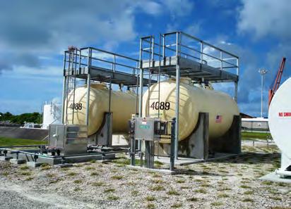
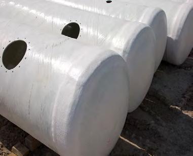
5 Tanks and vessels: FRP tanks, vessels and processing equipment are available from Beetle Plastics fabricated from any specialty or common thermoset resin of your choice. If you need design assistance, just provide your Beetle representative with the details of your service requirement and Beetle engineering will take it from there. Processing equipment specifications can include the manufacture and installation of the internals by Beetle; or provisions made for customer installation of the internals after delivery of the vessels. In any case, Beetle s staff of experienced design engineers will provide you with complete specifications tailored to meet your precise needs. Every project for Beetle is a custom project. Seldom are any two projects identical, due to the diverse needs of our customers. Beetle Plastics engineers and fabricators know how to do it right. On time. Tanks, vessels and processing equipment from Beetle can meet virtually any need or application: Standard diameters up to 14 feet, with heights as required Custom diameters available Stack heights to your requirements Standard materials or custom formulations


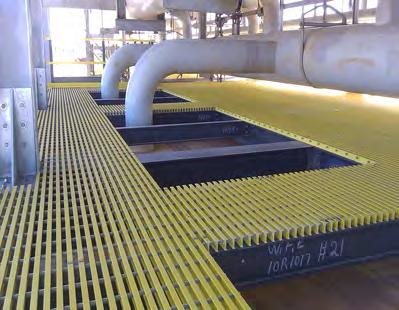
6 FRP piping and ductwork: Piping and ducting from Beetle Plastics can meet virtually any need or application you may have: Diameters from 1/2 inch to 14 feet Full vacuum and pressure services Filament wound or contact molded Wide variety of joints available Full range of fittings and connections Standard materials or custom formulations Round or rectangular ducting Full design and engineering support FRP piping and ducting from Beetle Plastics will exactly meet your specifications and requirements, especially when you allow us to be an integral partner in your design team. Now, special design factors are not surprises. Special installation considerations are planned instead of site adjusted. Site access problems are solved in advance instead of fixed in the field. Site assistance and testing services from Beetle help avoid all manner of site problems. And your piping or ducting installation will simply be installed easier and work better. Beetle will do it right. And, do it on time.


7 Engineering services: For FRP products to perform right in the field, it takes more than just quality manufacturing. It takes a high level of engineering and design skills with project related expertise - the kind that comes from years of experience. Beetle s engineers have the experience, the skills and the knowledge, to help you with virtually any project related to FRP solutions. Enlist Beetle s engineers to serve as an integral component of your design team. Let them participate in establishing early design parameters and help determine performance considerations. Then, rely on them, with confidence, to recommend and design the appropriate FRP products to meet your very specific needs. Field services: Beetle s field services team have truly been there and done that! Nothing takes the place of knowledge and experience. They have both. Call Beetle today for help with: Procurement assistance Anchors, guides and support systems Maintenance inspections Repair and installation services with certified personnel Equipment rebuilding On-site modifications In addition to full engineering and design support to meet your specific needs, Beetle provides many other services. Pre-assembly of your order in our fabrication shop, for example, can substantially increase the efficiency of your field erection and installation operations. And, that can mean a better value. Tap into engineering and field services from Beetle. Doing it right the first time, on time. Ardmore Industrial Airpark PO Box 1569 Ardmore, OK Fax info@beetleplastics.com Beetle Plastics, LLC
8 General Design Information
9 Series 1000 Fiberglass Corrosive Resistant Pipe and Fittings for Severely Corrosive Industrial Service Uses and Applications: Corrosive Services Waste Water and Sewage Systems Power Plant Piping Plant Piping Water Treatment Piping Piping Systems for Alkalies and Non-Oxidizing Acids Description: Filament wound fiberglass reinforced composite pipe. ASTM D-2996 (Isophthalic Resin) Classification Type 1, Grade 2, Class E. Composition: Nominal 40 mil glass veil and/or nexus reinforced corrosion liner, followed by a fiberglass filament wound structural overwrap. The liner thickness may be changed based on the application and service. Operating temperatures up to 180 ƒ. Pipe Sizes: Diameters, ranging from 1/2 Ø up to 168 Ø. Pipe available built to iron pipe outside diameters (ASTM D-2996, Table 3), as well as pipe built to chemical process piping inside diameter standards. 9
10 Series 1000 Fiberglass Pipe and Fittings Pipe Lengths: ½ Ø pipe and smaller is built in 5 foot lengths. ¾ Ø and 7/8 Ø pipe is built in 6 foot lengths. 1 Ø through 1 ½ Ø pipe is built in 10 foot lengths. 2 Ø through 4 Ø pipe is available in 20 foot lengths. 6 Ø pipe is available in 30 foot lengths. 8 through 168 pipe is available in 40 foot lengths. For selected pipe sized in 30 Ø and larger, 60 foot lengths are available. Longer lengths mean fewer field joints. Performance: Advantages: Good corrosion resistance over a wide temperature range. Temperatures from sub-zero to 180ºƒ. Working pressures from NBS-PS duct to 450 psi+, depending upon size and wall thickness. Vacuum to 14.7 psig for all sizes, by selection of wall thicknesses, ribs and filament wind angle. Available for earth burial, all depths, with selection of wall thickenesses, ribs and filament wind angle. Weighs 1/6 as much as steel. Thus, lower installation costs. The resins used in Series 1000 pipe meet the requirements of F.D.A. Regulations 21-CFR And 21CFR Smooth inner surface produces very low frictional loss for reduced pumping and fan blower costs. Hazen-Williams flow coefficient under 150. Recommended for a wide range of abrasion/corrosion applications. Consult with Beetle Plastics, LLC, or the resin manufacturer, for specific project recommendations. 10
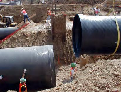
11 Series 1000 Fiberglass Pipe and Fittings Joining Systems: Bell (socket) and spigot structural adhesive weld bonded joints are available on diameters 12 and less. Diameters 14 and larger are the butt wrap joint method. Full size range of fittings are available to complete the piping system. Physical Properties: See Table 1 for typical physical properties of Series 1000 FW FRP Pipe. Mechanical Properties: These are conservative properties that can be used for the design of FW pipe for pressure, vacuum, supported span and burial conditions. Contact Beetle Plastics, LLC for recommendations on the appropriate design formulas to be used for FRP composite pipe. Burial Installations: As a custom manufacturer of pipe and fittings, we can design and build pipe to handle burial conditions ranging from live loads due to highway and rail traffic to earth loads of 100 feet or greater. We even have experience with underwater installations. Our Engineers will welcome the opportunity to work with you on a pipe design, backfill selection and installation methods to meet your specific requirements. The result will be your lowest cost per year of service life (installed basis). Support Span Installations: Again, we can design and build pipe to provide you the lowest cost for supported span installed pipe. Since we are not limited to just a few pipe wall thickness and filament winding angles we can select and choose the combination of pipe design and support design and cost that will provide your best buy. Consult with our engineers for assistance with your specific requirements. 11
12 Properties of Series 1000 Pipe: Series 1000 Fiberglass Pipe and Fittings Table 1 Corrosion Liner...Nominal 40 mil C-Veil and/or Nexus Reinforced Resin...Premium Grade Isophthalic Structural Wall...Filament Wound Overwrap Resin (FW Overwrap)...Premium Grade Isophthalic Elastic and Strength properties of Glass Filament Reinforced Wall Hoop Tensile: (Based on loading of pipe hydrostatically) Ultimate (porosity)...20,000 psi Yield...12,800 psi Allowable... 6,700 psi Modulus of Elasticity...3,600,000 psi Tensile: (Based on loading of pipe as a tension member) Ultimate (rupture)...12,200 psi Yield... 5,000 psi Allowable...4,000 psi Modulus of Elasticity...1,800,000 psi Flexural: (Based on loading of pipe as a beam) Ultimate (rupture)...15,700 psi Yield... 6,100 psi Allowable... 4,400 psi Modulus of Elasticity... 1,700,000 psi Torsion: (Based on loading of pipe as a shaft in torsion) Ultimate (rupture)... 16,200 psi Allowable Shear... 5,500 psi Shear Modulus ,000 psi Compression: (Based on loading of pipe as a short column) Ultimate (rupture)... 11,200 psi Yield... 7,000 psi Allowable... 3,700 psi Modulus of Elasticity... 1,400,000 psi Thermal Properties: Coefficient of Thermal Expansion in./in./deg.f Thermal Conductivity BTU/hr.sq.ft/deg.F/in.thick 12
13 Uses and Applications: Series 5000 Fiberglass Pipe and Fittings for Severely Corrosive Industrial Service Chemical Process Piping Organic Chemicals Acid Drains Corrosive Services Waste Water and Sewage Systems Process Plant Piping Power Plant Piping Bleach Processing Chlorine and Chlorinated Water Food Processing Plant Piping Plant Piping Water Treatment Piping Brine and Brackish Water Potable Water Piping Systems for Oxidizing Chemicals and Acids Piping Systems for Alkalies and Non-Oxidizing Acids Industrial Service for Severely Corrosive Liquids Description: Filament wound fiberglass reinforced vinyl ester epoxy composite pipe. ASTM D-2996 Classification Type 1, Grade 2, Class E. Composition: Nominal 40 to 50 mil Glass Veil and/or Nexus Reinforced Corrosion Liner, followed by a Fiberglass Filament Wound Structural Overwrap. A premium grade vinyl ester resin, pigmented dark grey for UV inhibition, is used throughout the laminate. Operating Temperatures up to 180 f. 13
14 Series 5000 Fiberglass Pipe and Fittings Pipe Sizes: Diameters, ranging from 1/2 Ø up to 168 Ø. Pipe available built to iron pipe outside diameters (ASTM D-2996, Table 3), as well as pipe built to chemical process piping inside diameter standards. Pipe Lengths: ½ Ø pipe and smaller is built in 5 foot lengths. ¾ Ø and 7/8 Ø pipe is built in 6 foot lengths. 1 Ø through 1 ½ Ø pipe is built in 10 foot lengths. 2 Ø through 4 Ø pipe is available in 20 foot lengths. 6 Ø pipe is available in 30 foot lengths. 8 through 168 pipe is available in 40 foot lengths. For selected pipe sized in 30 Ø and larger, 60 foot lengths are available. Longer lengths mean fewer field joints. Performance: Good corrosion resistance over a wide temperature range. Temperatures from sub-zero to 180 f. Advantages: Working pressures from NBS-PS duct to 450 psi+, depending upon size and wall thickness. Vacuum to psig for all sizes, by selection of wall thicknesses, ribs and filament wind angle. Available for earth burial, all depths, with selection of wall thicknesses, ribs and filament wind angle. Weighs 1/6 as much as steel. Thus, lower installation costs. The resins used in Series 5000 pipe meet the requirements of F.D.A. Regulations 21-CFR and 21-CFR Smooth inner surface produces very low frictional loss for reduced pumping and fan blower costs. Hazen-Williams flow coefficient under 150. Recommended for a wide range of corrosion applications. Consult with Beetle Plastics LLC or the resin manufacturer for specific project recommendations. 14
15 Series 5000 Fiberglass Pipe and Fittings Joining Systems: Bell (socket) and spigot structural adhesive weld bonded joints are available on diameters 12" and less. Diameters 14" and larger are the butt wrap joint method. Flanges, all sizes through 144 Ø, including the superior filament wound socket flanges for sizes ½ Ø through 36 Ø ANSI 150lb., 300lb. And 600lb all available as standard. Any pressure rating and drilling pattern available on order. VanStone, Loose Ring Style, Flanges. Flange Spacers, all diameters, bolt hole patterns and thicknesses, built to order. Bell and Spigot O Ring Joints, through 84 Ø Bell and Spigot O Ring Joints with Locking Key for Retained Ends. Mechanical Couplings, Including Victaulic and Taylor-Kerr. Expansion Joints, including Triple O Ring Style for Fly Ash Lines. Repair (maintenance) couplings. Physical Properties: See Table 1 for typical physical properties of Series 5000 FW FRP pipe. Mechanical Properties: These are conservative properties that can be used for the design of FW pipe for pressure, vacuum, supported span and burial conditions. Contact Beetle Plastics LLC for recommendations on the appropriate design formulas to be used for FRP composite pipe. Burial Installations: As a custom manufacturer of pipe and fittings, we can design and build pipe to handle burial conditions ranging from live loads due to highway and rail traffic to earth loads of 100 feet or greater. We even have experience with underwater installations. Our engineers will welcome the opportunity to work with you on a pipe design, backfill selection and installation methods to meet your specific requirements. The result will be your lowest cost per year of service life (installed basis). Support Span Installations: Again, we can design and build pipe to provide you the lowest cost for supported span installed pipe. Since we are not limited to just a few pipe wall thickness and filament winding angles we can select and choose the combination of pipe design and support design and cost that will provide your best buy. Consult with our engineers for assistance with your specific requirements. 15
16 Series 5000 Fiberglass Pipe and Fittings Fittings: Elbows, standard are 22 ½, 30, 45 and 90. Any angle elbow available on special order. Elbows through 48 Ø are available as smooth radius. Mitered elbows are available in all sizes. Reducing Elbows Tees Reducing Tees Concentric Taper Body Reducers Eccentric Taper Body Reducers Saddles, with FRP and Stainless Steel Threaded Outlets Bell Outlets, Spigot Outlets and Flanged Outlets Wear Pads (Blank Saddles) Crosses Reducing Crosses Laterals Reducing Laterals True Wyes P-Traps and 180 U-Bends Floor Drains Pipe Couplings Threaded (NPT) Couplings Adapters, Bell and NPT Thread (Male or Female Threads available) Pipe Nipples Reducing Bushings and Threaded Adapter Bushings Fitting and Pipe Plugs Pipe Caps Blind Flanges Threaded Flanges Reducing Flanges Orifice Flanges All fittings are available as adhesive socket, plain end, flanged end, bell and spigot O ring or any combination. Fittings are available from ½ Ø through 168 Ø. 16
17 Properties of Series 5000 Pipe: Series 5000 Fiberglass Pipe and Fittings Table 1 Corrosion Liner...Nominal 40 to 50 mil C-Veil and/or Nexus Reinforced Resin...Premium Grade Vinyl Ester Structural Wall...Filament Wound Overwrap Resin (FW Overwrap)...Premium Grade Vinyl Ester Elastic and Strength Properties of Glass Filament Reinforced Wall Hoop Tensile: (Based on loading of pipe hydrostatically) Ultimate (porosity)... 20,000 psi Yield... 12,800 psi Allowable...6,700 psi Modulus of Elasticity... 3,600,000 psi Tensile: (Based on loading of pipe as a tension member) Ultimate (rupture)... 12,200 psi Yield...5,000 psi Allowable... 4,000 psi Modulus of Elasticity...1,800,000 psi Flexural: (Based on loading of pipe as a beam) Ultimate (rupture)... 15,700 psi Yield...6,100 psi Allowable...4,400 psi Modulus of Elasticity...1,700,000 psi Torsion: (Based on loading of pipe as a shaft in torsion) Ultimate (rupture)...16,200 psi Allowable Shear...5,500 psi Shear Modulus...750,000 psi Compression: (Based on loading of pipe as a short column) Ultimate (rupture)...11,200 psi Yield...7,000 psi Allowable...3,700 psi Modulus of Elasticity...1,400,000 psi Thermal Properties: Coefficient of Thermal Expansion in./in./deg.f Thermal Conductivity BTU/hr.sq.ft/deg.F/in.thick 17
18 Series 9100 Fiberglass Pipe and Fittings for Corrosive Industrial Service Uses and Applications: Description: Chemical Proceess Piping Organic Chemicals Acid Drains Corrosive Services Process Plant Piping Power Plant Piping Plant Piping Water Treatment Piping Brine and Brackish Water Filament wound fiberglass reinforced composite pipe. ASTM D-2996 Classification Type 1, Grade 2, Class E. Composition: Nominal 110 mil glass veil and/or nexus reinforced corrosion liner, followed by a fiberglass filament wound structural overwrap. A premium grade vinyl ester resin, pigmented dark grey for UV inhibition, is used throughout the laminate. VE/ISO. Operating Temperatures up to 250 ƒ. 18
19 Series 9100 Fiberglass Pipe and Fittings Pipe Sizes: Diameters, ranging from 1/2 Ø up to 168 Ø. Pipe available built to Iron Pipe Outside Diameters (ASTM D-2996,) as well as Pipe built to Chemical Process Piping Inside Diameter Standards. Pipe Lengths: Performance: Advantages: ½ Ø pipe and smaller is built in 5 foot lengths. ¾ Ø and 7/8 Ø pipe is built in 6 foot lengths. 1 Ø through 1 ½ Ø pipe is built in 10 foot lengths. 2 Ø through 4 Ø pipe is available in 20 foot lengths. 6 Ø pipe is available in 30 foot lengths. 8 through 168 pipe is available in 40 foot lengths. For selected pipe sized in 30 Ø and larger, 60 foot lengths are available. Longer lengths mean fewer field joints. Good corrosion resistance over a wide temperature range. Temperatures from. sub-zero to 250ºƒ. Working pressures from NBS-PS Duct to 450 psi+, depending upon size and wall thickness. Vacum to 14.7 psig for all sizes, by selection of wall thicknesses, ribs and filament wind angle. Available for earth burial, all depths, with selection of wall thickenesses, ribs and filament wind angle. Weighs 1/6 as much as steel. Thus, lower installation costs. The Resins used in Series 9100 Pipe meet the requirements of F.D.A. Regulations 21-CFR and 21CFR Smooth inner surface produces very low frictional loss for reduced pumping and fan blower costs. Hazen-Williams flow coefficient under 150. Recommended for a wide range of corrosion applications. Consult with Beetle Plastics or the resin manufacturer for specific project recommendations. 19
20 Series 9100 Fiberglass Pipe and Fittings Joining Systems: Bell (socket) and spigot structural adhesive weld bonded joints. Flanges, all sizes through 84 Ø, including the superior filament wound socket flanges for sizes through ½ Ø through 36 Ø ANSI 150lb., 300lb. And 600lb all available as standard. Any pressure rating and drilling pattern available on order. VanStone, Loose Ring Style, Flanges. Flange Spacers, all diameters, bolt hole patterns and thicknesses, built to order. Bell and Spigot O Ring Joints, through 84 Ø Bell and Spigot O Ring Joints with Locking Key for Retained Ends. Mechanical Couplings, Including Victaulic and Taylor-Kerr. Expansion Joints. Physical Properties: See Table 1 for typical physical properties of Series 9100 FW FRP pipe. Mechanical Properties: These are conservative properties that can be used for the design of FW pipe for pressure, vacuum, supported span and burial conditions. Contact Beetle Plastics, for recommendations on the appropriate design formulas to be used for FRP composite pipe. Burial Installations: As a custom manufacturer of pipe and fittings, we can design and build pipe to handle burial conditions ranging from live loads due to highway and rail traffic to earth loads of 100 feet or greater. We even have experience with underwater installations. Our engineers will welcome the opportunity to work with you on a pipe design, backfill selection and installation methods to meet your specific requirements. The result will be your lowest cost per year of service life (installed basis). Support Span Installations: Again, we can design and build pipe to provide you the lowest cost for supported span installed pipe. Since we are not limited to just a few pipe wall thickness and filament winding angles we can select and choose the combination of pipe design and support design and cost that will provide your best buy. Consult with our engineers for assistance with your specific requirements. 20
21 Series 9100 Fiberglass Pipe and Fittings Fittings: Elbows, standard are 22 1/2, 30, 45 and 90. Any angle elbow available on Special Order. Elbows through 48 Ø are available as smooth radius. Mitered elbows are available in all sizes. Reducing Elbows Tees Reducing Tees Concentric Taper Body Reducers Eccentric Taper Body Reducers Saddles, with FRP and Stainless Steel Threaded Outlets, Bell Outlets, Spigot Outlets and Flanged Outlets Wear Pads (blank saddles) Crosses Reducing Crossed Laterals Reducing Laterals True Wyes P-Traps and 180 U-Bends Floor Drains Pipe Couplings Threaded (NPT) Couplings Adapters, Bell x NPT Thread (Male or Female Threads Available) Pipe Nipples Reducing Bushings and Threaded Adapter Bushings Fitting and Pipe Plugs Pipe Caps Blind Flanges Threaded Flanges Reducing Flanges Orifice Flanges All fittings are available as Adhesive Socket, Plain End, Flanged End, Bell and Spigot O Ring or any combination. Fittings are available from ½ Ø through 168 Ø. We welcome the opportunity to work with our customers on Special Fittings. 21
22 Properties of Series 9100 Pipe: Series 9100 Fiberglass Pipe and Fittings Table 1 Corrosion Liner... Nominal 110 mil C-Veil and/or Nexus Reinforced Resin...Premium Grade Vinyl Ester Structural Wall...Filament Wound Overwrap Resin (FW Overwrap)... Premium Grade Isopthalic Polyester Elastic and Strength properties of Glass Filament Reinforced Wall Hoop Tensile: (Based on loading of pipe hydrostatically) Ultimate (porosity)... 20,000 psi Yield... 12,800 psi Allowable...6,700 psi Modulus of Elasticity... 3,600,000 psi Tensile: (Based on loading of pipe as a tension member) Ultimate (rupture)... 12,200 psi Yield...5,000 psi Allowable... 4,000 psi Modulus of Elasticity...1,800,000 psi Flexural: (Based on loading of pipe as a beam) Ultimate (rupture)... 15,700 psi Yield...6,100 psi Allowable...4,400 psi Modulus of Elasticity...1,700,000 psi Torsion: (Based on loading of pipe as a shaft in torsion) Ultimate (rupture)...16,200 psi Allowable Shear...5,500 psi Shear Modulus...750,000 psi Compression: (Based on loading of pipe as a short column) Ultimate (rupture)...11,200 psi Yield...7,000 psi Allowable...3,700 psi Modulus of Elasticity...1,400,000 psi Thermal Properties: Coefficient of Thermal Expansion in./in./deg.f Thermal Conductivity BTU/hr.sq.ft/deg.F/in.thick 22
23 Series 9500-A Fiberglass Abrasion Resistant Pipe and Fittings for Severely Abrasive & Corrosive Industrial Service Uses and Applications: Description: Corrosive and Abrasive Slurries Waste Water and Sewage Systems Power Plant Bottom Ash Discharge Power Plant & Fly Ash Piping Plant Piping Water Treatment Piping Piping Systems for alkalies and Non-Oxidizing Acids Filament wound fiberglass reinforced vinyl ester epoxy composite pipe. ASTM D-2996 Classification Type 1, Grade 2, Class E. Composition: Nominal 110 mil glass veil and/or nexus reinforced corrosion liner, followed by a fiberglass filament wound structural overwrap. The liner thickness may be changed based on the application and service. The liner additive is a material with a hardness of 9 compared the diamond hardness of 10. Operating temperatures up to 300 ƒ. 23
24 Series 9500-A Fiberglass Abrasion Resistant Pipe and Fittings Pipe Sizes: Diameters, ranging from 1/2 Ø up to 168 Ø. Pipe available built to Iron Pipe Outside Diameters (ASTM D-2996,) as well as Pipe built to Chemical Process Piping Inside Diameter Standards. Pipe Lengths: Performance: Advantages: ½ Ø pipe and smaller is built in 5 foot lengths. ¾ Ø and 7/8 Ø pipe is built in 6 foot lengths. 1 Ø through 1 ½ Ø pipe is built in 10 foot lengths. 2 Ø through 4 Ø pipe is available in 20 foot lengths. 6 Ø pipe is available in 30 foot lengths. 8 through 168 pipe is available in 40 foot lengths. For selected pipe sized in 30 Ø and larger, 60 foot lengths are available. Longer lengths mean fewer field joints. Good corrosion resistance over a wide temperature range. Temperatures from. sub-zero to 300ºƒ. Working pressures from NBS-PS Duct to 450 psi+, depending upon size and wall thickness. Vacum to 14.7 psig for all sizes, by selection of wall thicknesses, ribs and filament wind angle. Available for earth burial, all depths, with selection of wall thickenesses, ribs and filament wind angle. Weighs 1/6 as much as steel. Thus, lower installation costs. The Resins used in Series 9100 Pipe meet the requirements of F.D.A. Regulations 21-CFR and 21CFR Smooth inner surface produces very low frictional loss for reduced pumping and fan blower costs. Hazen-Williams flow coefficient under 150. Recommended for a wide range of corrosion applications. Consult with Beetle Plastics or the resin manufacturer for specific project recommendations. 24
25 Series 9500-A Fiberglass Abrasion Resistant Pipe and Fittings Joining Systems: Bell (socket) and spigot structural adhesive weld bonded joints are available on diameters 12" and less. Diameters 14" and larger are the butt wrap joint method. Flanges, all sizes through 144 Ø, including the superior filament wound socket flanges for sizes ½ Ø through 36 Ø ANSI 150lb., 300lb. And 600lb all available as standard. Any pressure rating and drilling pattern available on order. VanStone, Loose Ring Style, Flanges. Flange Spacers, all diameters, bolt hole patterns and thicknesses, built to order. Bell and Spigot O Ring Joints, through 84 Ø Bell and Spigot O Ring Joints with Locking Key for Retained Ends. Mechanical Couplings, Including Victaulic and Taylor-Kerr. Expansion Joints, including Triple O Ring Style for Fly Ash Lines. Repair (maintenance) couplings. Physical Properties: See Table 1 for typical physical properties of Series 9500-A FW FRP pipe. Mechanical Properties: These are conservative properties that can be used for the design of FW pipe for pressure, vacuum, supported span and burial conditions. Contact Beetle Plastics, for recommendations on the appropriate design formulas to be used for FRP composite pipe. Burial Installations: As a custom manufacturer of pipe and fittings, we can design and build pipe to handle burial conditions ranging from live loads due to highway and rail traffic to earth loads of 100 feet or greater. We even have experience with underwater installations. Our engineers will welcome the opportunity to work with you on a pipe design, backfill selection and installation methods to meet your specific requirements. The result will be your lowest cost per year of service life (installed basis). Support Span Installations: Again, we can design and build pipe to provide you the lowest cost for supported span installed pipe. Since we are not limited to just a few pipe wall thickness and filament winding angles we can select and choose the combination of pipe design and support design and cost that will provide your best buy. Consult with our engineers for assistance with your specific requirements. 25
26 Series 9500-A Fiberglass Abrasion Resistant Pipe and Fittings Fittings: Elbows, standard are 22 1/2, 30, 45 and 90. Any angle elbow available on Special Order. Elbows through 48 Ø are available as smooth radius. Mitered elbows are available in all sizes. Reducing Elbows Tees Reducing Tees Concentric Taper Body Reducers Eccentric Taper Body Reducers Saddles, with FRP and Stainless Steel Threaded Outlets, Bell Outlets, Spigot Outlets and Flanged Outlets Wear Pads (blank saddles) Crosses Reducing Crossed Laterals Reducing Laterals True Wyes P-Traps and 180 U-Bends Floor Drains Pipe Couplings Threaded (NPT) Couplings Adapters, Bell x NPT Thread (Male or Female Threads Available) Pipe Nipples Reducing Bushings and Threaded Adapter Bushings Fitting and Pipe Plugs Pipe Caps Blind Flanges Threaded Flanges Reducing Flanges Orifice Flanges All fittings are available as Adhesive Socket, Plain End, Flanged End, Bell and Spigot O Ring or any combination. Fittings are available from ½ Ø through 168 Ø. We welcome the opportunity to work with our customers on Special Fittings. 26
27 Series 9500-A Fiberglass Abrasion Resistant Pipe and Fittings Properties of Series 9500-A Pipe: Table 1 Abrasion Resistant/Corrosion Liner... Nominal 110 mil C-Veil and/or Nexus Reinforced Resin...Premium Grade Vinyl Ester Structural Wall...Filament Wound Overwrap Resin (FW Overwrap)...Premium Grade Vinyl Ester Elastic and Strength properties of Glass Filament Reinforced Wall Hoop Tensile: (Based on loading of pipe hydrostatically) Ultimate (porosity)... 20,000 psi Yield... 12,800 psi Allowable...6,700 psi Modulus of Elasticity... 3,600,000 psi Tensile: (Based on loading of pipe as a tension member) Ultimate (rupture)... 12,200 psi Yield...5,000 psi Allowable... 4,000 psi Modulus of Elasticity...1,800,000 psi Flexural: (Based on loading of pipe as a beam) Ultimate (rupture)... 15,700 psi Yield...6,100 psi Allowable...4,400 psi Modulus of Elasticity...1,700,000 psi Torsion: (Based on loading of pipe as a shaft in torsion) Ultimate (rupture)...16,200 psi Allowable Shear...5,500 psi Shear Modulus...750,000 psi Compression: (Based on loading of pipe as a short column) Ultimate (rupture)...11,200 psi Yield...7,000 psi Allowable...3,700 psi Modulus of Elasticity...1,400,000 psi Thermal Properties: Coefficient of Thermal Expansion in./in./deg.f Thermal Conductivity BTU/hr.sq.ft/deg.F/in.thick 27
28 Resin Construction Type Type of Liner Resin for Liner Resin for Structural Series 1000 (Filament Wound) 40 mil veil and/or Nexus reinforced Premium Grade Isophthalic Polyester Premium Grade Isophthalic Polyester Series 1500 (Filament Wound) 40 mil veil and/or Nexus Reinforced Premium Grade Vinyl ester Premium Grade Isophthalic Polyester Series 5000 (Filament Wound) mil veil and/or Nexus reinforced Premium Grade Vinyl ester Premium Grade Vinyl ester Series 5700 (Filament Wound) mil veil and/or Nexus reinforced Premium Grade High Temperature Vinyl ester Premium Grade High Temperature Vinyl ester Series 9000 (Filament Wound) Nominal 110 mil veil and/or Nexus reinforced Premium Grade Isopthalic Polyester Premium Grade Isopthalic Polyester Series 9100 (Filament Wound) Nominal 110 mil veil and/or Nexus reinforced Premium Grade Vinyl ester Premium Grade Isopthalic Polyester Series 9100-A (Filament Wound) Nominal 110 mil veil and/or Nexus reinforced Premium Grade Abrasion Resistant Vinyl ester Premium Grade Isopthalic Polyester Series 9500 (Filament Wound) Nominal 110 mil veil and/or Nexus reinforced Premium Grade Vinyl ester Premium Grade Vinyl ester Series 9500-A (Filament Wound) Nominal 110 mil veil and/or Nexus reinforced Premium Grade Abrasion Resistant Vinyl ester Premium Grade Vinyl ester 28
29 Resin Construction Type Type Of Liner Resin For Liner Resin For Structural Series 9700 (Filament Wound) Nominal 110 mil veil and/or Nexus reinforced Premium Grade High Temperature Vinyl ester Premium Grade High Temperature Vinyl ester Series (Contact Molded) Nominal 110 mil chopped strand reinforced Premium Grade Isophthalic Polyester Premium Grade Isophthalic Polyester Series (Contact Molded) Nominal 110 mil chopped strand reinforced Premium Grade Vinyl ester Premium Grade Isophthalic Polyester Series (Contact Molded Nominal 110 mil chopped strand reinforced Premium Grade Vinyl ester Premium Grade Vinyl ester Series (Contact Molded Nominal 110 mil chopped strand reinforced Premium Grade High Temperature Vinyl ester Premium Grade High Temperature Vinyl ester 29
30 STANDARD PIPE DIAMETER Beetle Plastics LLC has available pipe and duct mandrels in many different sizes. The available mandrels are listed in the table below. Starting with the 8 diameter sizes, many of the mandrels are 40 ft. in length reducing the field joining labor and costs. Mandrel Diameter The mandrel O.D. establishes the pipe inside diameter. The wall thickness selected establishes the pipe outside diameter. A wide range of pressure and service ratings are available. Included are mandrels that will allow piping 12 diameter and smaller to be manufactured to iron pipe O.D. standards. 30
31 Lined vs. Unlined FW FRP Composite Pipe It has always been our thesis that all FRP composite pipe for fluid service should have an internal corrosion barrier/liner. Therefore, it has been our policy to supply all pipe, with such a corrosion barrier/liner. The type and thickness of this corrosion barrier/liner will depend upon the specific service environment. The thickness of a corrosion barrier/liner can range from a 40 mil (0.040 ) for cooling water applications, to over 200 mil (0.200 ) SPI type for wet chlorine gas service. The purpose of this bulletin is to detail why we believe it is important to provide FRP composite pipe with an internal corrosion barrier/liner. Corrosion Resistance: We realize that some pipe manufacturers market a pipe without a corrosion barrier/liner (typically called unlined pipe). Interestingly, in most cases, the resins used for the unlined pipe series also have lower corrosion resistance capabilities, and lower service temperature limitations. All pipe manufacturers provide a corrosion barrier/liner in their pipe intended for moderate to severe corrosive applications. Since fiberglass reinforced composite pipe is typically used for applications where corrosion is a consideration, it seems only logical to use a corrosion resistant product. In FRP composite pipe, the resin matrix provides the corrosion resistance. The higher the resin content of the laminate exposed to the service environment, the better the corrosion resistance. Also, within the limits of the resin system, the thicker the corrosion barrier/liner, the greater the corrosion resistance. Unlined pipe typically has a resin content of just 30 to 40 percent in the surface exposed to the service environment. In pipe built with a corrosion barrier/ liner, the resin content is typically 80 to 90 percent. What does all this mean to the end user? In a filament wound composite pipe, the cost of adding a corrosion barrier/liner is not all that great in comparison to the true cost of the pipe. The selection of the proper type and thickness of the corrosion barrier/liner can more than double the service life of the pipe. Since fiberglass pipe is typically being bought to provide longer service life than other alternate materials, the addition of a corrosion barrier/liner can become an important cost savings to the end user, providing the lowest cost per year of service life. Structural Integrity: While typically the corrosion barrier/liner is not counted on for adding strength to the pipe, it does enhance the structural integrity. Depending upon the service environment, sometimes the structural properties of the SPI type corrosion barrier/liner are included in determining the pressure rating of the pipe. One of the advantages of properly designed and manufactured fiberglass filament wound composite pipe is that it will typically show signs of weeping through the pipe wall when over-pressurized, long before a catastrophic failure occurs. Such weeping occurs by fluid wicking following the continuous glass roving used in filament winding. The weakest portion of the structural wall is the glass/resin interface. The corrosion barrier/liner, thus, serves to prevent the fluid media from getting to that continuous fiberglass filament. From a purely structural viewpoint, the ideal corrosion barrier/liner would be a rubber bag. This rubber liner would continue to stretch, allowing the structural wall to fully take advantage of the superstrong, continuous glass filaments until they actually broke. A properly designed resin corrosion barrier/ liner serves the same function allowing the structural wall to take the full load without concern for pipe wall weeping. 31
32 Lined vs. Unlined FW FRP Composite Pipe Abrasion Resistance: There is an element of abrasive wear in almost all fluid service applications. In the concern for corrosion resistance, this abrasion element of the environment is often overlooked. Especially for pipe subjected to high flows or where there may be particulate matter contamination (i.e. cooling water applications, river water, waste handling, etc.) abrasion design needs to be considered for all FRP composite pipe. As with corrosion resistance, the resin matrix provides the abrasion resistance. With a properly designed and selected corrosion barrier/liner, the abrasion resistance (and the pipe life) can be up to ten times greater than for unlined pipe, where the glass filaments are directly exposed to the service wear. With unlined pipe, very rapid wear can occur, with the roving filaments being picked away from the surface. Through further modifications of the corrosion barrier/liner, consisting of proper resin selection, proper type of non-glass reinforcement, and armoring modifiers, the abrasion resistance of the corrosion barrier can be further improved. Another compelling reason for always using a corrosion barrier/liner in FRP composite pipe is to provide the capability for changes in service environment. Even if the current service environment would not benefit from the additional protection of a corrosion barrier/liner, the addition of a corrosion barrier/liner provides insurance that future changes in the service stream can take place without concern for the life of the pipe. Perhaps the nature of the waste stream may be different five or ten years from today. Perhaps even for relatively mild cooling water or river water service, the end user may want to add treatment chemicals in the future. The zebra mussel that is attaching itself to the insides of pipe has made headlines. The addition of a corrosion barrier/ liner for pipe would provide additional abrasion resistance in removing, by mechanical means or hydro blasting, such mussel buildups. The small additional cost for a corrosion barrier/liner can be a very inexpensive insurance policy for the future. In-service Costs: One of the advantages of FRP composite plastic pipe is its internal smoothness over its entire service life, especially when compared to other materials such as concrete, steel, etc. This smoothness is translated into less friction and, thus, lower pumping cost. In some cases, even a smaller diameter pipe can be used. Even small differences in the smoothness of the pipe interior can be translated into dollar savings in electricity or fuel (for the pumps). The glass smoothness of the high resin content corrosion barrier/liner is measurably better than for unlined FRP pipe. In addition, the energy savings advantage of the resin-rich corrosion barrier/liner increases with age. Summary: Except for conduit, in almost all instances a corrosion barrier/liner can be economically justified for FRP composite pipe. We recommend, as a minimum, a 40 mil thick C-veil and/or Nexus reinforced corrosion barrier/liner. For moderate and severe corrosive environments, an even thicker corrosion barrier/liner should be considered. We will be glad to work with you in selecting the best corrosion barrier/liner for their service environment. We are confident that lined pipe will provide the end user their lowest cost per year of service life and, thus, their Best Buy. 32
33 Bolts, Nuts and Washers The recommended type of hex head bolts, nuts and washers for Beetle Plastics LLC flanges are shown below. If all-thread studs are used, add the thickness of the nut plus the length of three threads to the bolt lengths shown. For the assembly of two flanges not shown below, hex head bolt length may be calculated by adding the total of the thickness of the two flanges being joined plus the gasket thickness, plus two times (2x) the washer thickness plus the thickness of the nut plus the length of three threads. Flange thickness for all Beetle Plastics LLC flanges are shown in the Beetle Plastics LLC catalog. Beetle Plastics LLC Flanges ANSI B16.5 Class 150 Drilling Nominal Flange Size (in.) Bolt Diameter (in.) Number of Bolts Filament- Wound To Filament- Wound Bolt Lengths (1) Filament- Wound To Steel Washer O.D. (in.) Washer Thickness (in.) Nut Thickness (in.) ½ ½ 4 2-1/ ¾ ½ 4 2-1/ ½ 4 2-1/2 2-1/ /2 ½ / / / /2 5/ / /2 3-1/ / /2 3-1/ ¾ 8 3-1/2 3-3/ ¾ 8 4-1/ ¾ / / /2 4-3/ / / /2 5-1/ / / /4 6-1/ / /4 7-1/ / / / /2 7-1/ / /2 7-3/ Regular Hex Head Bolts, ANSI B Regular Hex Nuts ANSI B Type A Plain, Narrow Series. ANSI B R (Dimensions agree with SAE Standard and ANSI/ASTM Specification F436.) 4. Maintain end point clearance of bolts on inside radius of 2-, 3- and 4-inch Beetle Plastics LLC flanged ANSI elbows by using additional washers or shims under bolt heads as required. 33
34 Drawings and Dimensions 34
35 Figure #1 Coupling, Pipe Bell-End Size A B Pipe O.D. Weight 1/ / / /
36 Sawcuts at 90º Figure #1-R Coupling, Repair (Maintenance) Size Standard Coupling Length L Adhesive Kits Required Weight 1/ oz.3 3/ oz oz.4 1 1/ oz oz / oz oz oz oz oz oz oz oz oz oz oz oz 33.2 Maintenance coupling kit includes inner and out 180 sections and hose clamps. Adhesive sold separately. 1/2 to 12 couplings are rated for 150 psi hydrostatic pressure. Maintenance couplings 14 and larger are rated for 50 psi. Rated pressure based on RP-34 or equivalent adhesive. 36
37 Figure #2-L Coupling, Threaded Long Size A B Weight 1/ / / / / Figure #2-L/2 Coupling, Threaded Half Size A Weight 1/ / / / /
38 Size A Weight 1/ / / / / Figure #2-XL Coupling, Threaded Extra Long Figure #2-XL/2 Coupling, Threaded Extra Long Half Size A Weight 1/ / / / / Figure #2-S Coupling, Threaded Short Size A Weight 1/ / / /
39 Figure #3 Adapter, Female, Bell x Thread Size A B Weight 1/ / / / Figure #4 Adapter, Male, Bell x Thread Size A B C Weight / C 39
40 Figure #5 Adapter, Grooved, Bell x Victaulic C Size A B C Weight
41 Figure #6 Nipple, Threaded Pipe Size A Std. Lgth B Weight 1/ / / / / B Figure #6-L Nipple, Long Threaded Pipe Size A Std. Lgth Weight / Nipple lengths and sizes other than shown are available on request. 41
42 Figure #7 Nipple, Spigot x Male Threaded Pipe Size A Std. Lgth B 1/ / / / / Note: 6 maximum length. Nipple lengths and sizes other than shown are available on request. Figure #7-L Nipple, Long Spigot x Male Threaded Pipe Size A Std. Lgth / Nipple lengths and sizes other than shown are available on request. 42
43 Figure #8 Nipple, Pipe Size A Weight 1/ / / / Nipple lengths and sizes other than shown are available on request. 43
44 Figure #9 Bushing, Reducing Size A B /2 thru 3/4 1 1/ /2 thru /2 thru 1 1/2 2 1/ /2 thru /2 thru 2 1/ /2 thru /2 thru /2 thru /2 thru /2 thru 10 Larger sizes are available on request. Bushings 6 and larger are not recommended for pressure greater than 50 psi. Figure #10 Bushing, Threaded Reducing Size A NPT /2 thru 3/4 1 1/ /2 thru 1 1/ /2 thru 1 1/2 2 1/ /2 thru /2 thru 2 1/ /2 thru /2 thru /2 thru /2 thru /2 thru 8 Larger sizes are available on request. Stainless steel bushings are available on special orders. Bushings 6 and larger are not recommended for pressure greater than 50 psi. 44
45 Figure #11 Cap, Pipe Size A B / / For pipe caps larger the 12, refer to Figure #99, End Domes. Figure #11-T Cap, Threaded Pipe Size A Weight / /
46 Figure #12 Plug, Pipe Size A 1/2.88 3/ / / Pipe fits pipe I.D. State pipe I.D. or manufacturer. Refer to Figure #11 for sizes larger than 4. Size A 1/2.87 3/ / / Figure #13 Plug, Fitting Plugs fits fitting socket. Larger sizes available on request. Fitting plugs to size 6 are rated for 150 psi working pressure. Sizes 8 through 12 are reduced to a rated working pressure of 75 psi. Figure #13-T Plug, Threaded Fitting Size A Weight 1/ / / / Larger sizes available on request. 4, 6 and 8 plugs also available with recessed heads. 46
47 Figure #14 Flange, Filament Wound 300 lb. Socket Size A Flg. O.D. B Bolt Circle C Number Holes D Dia. Holes E G Weight / / / / / / / / / / / / Flange drilled to ANSI B lb. Higher pressure rating available. Please refer to Appendix B for Flange Assembly Instructions. 47
48 Figure #15 Flange, Filament Wound 150 lb. Socket Size A Flg. O.D. B Bolt Circle C Number Holes D Dia. Holes E F G Weight 1/ / / / / / / / / / / / / / / / / / / / / / / / Flange drilled to ANSI B lb. Use SAE washers with Figure #15 flanges and all flanged fitting in this catalog. Figure #15-25 Flange, Filament Wound 25 psi Socket Size A Flg. O.D. B Bolt Circle C Number Holes D Dia. Holes E F G Weight / / / / / / / / / / / Flanges rated for 25 psi are designed to be bolted to flat face flanges only. 25 psi flanges are designed for low pressure applications such as tank outlets, manway and duct flanges. Flange drilled to ANSI B16.5, 150 lb. is also available, please specify on order. 48
49 Figure #15-A Flange, Filament Wound 150 lb. Stub Size A B Weight 1/ / / / Flange drilled to ANSI B16.5, 150 lb. See Figure #15 for number, position and size of bolt holes. Please refer to Appendix B for Flange Assembly instructions. Weld kits are available for attachment to FRP tanks, piping and equipment. 49
50 Figure #15-A-25 Flange, Filament Wound 25 psi Stub Size A B Weight Flanges rated for 25 psi are designed to be bolted to flat face flanges only. 25 psi flanges are designed for low pressure applications such as tank outlets, manway and duct flanges. Weld kits are available for attachment to FRP tanks, piping and equipment. Figure #15-A-VS Flange, Filament Wound 150 lb. Van-Stone Stub Size A B Weight / / Special Order 36 Special Order Flange drilled to ANSI B16.5, 150 lb. Please refer to Appendix B for Flange Assembly instructions. Weld kits are available for attachment to FRP tanks, piping and equipment. 50
51 Figure #15-A-VS-25 Flange, Filament-Wound 25 psi Van-Stone Stub Size A B Weight Special Order 36 Special Order Flanges rated for 25 psi are designed to be bolted to flat face flanges only. 25 psi flanges are designed for low pressure applications such as tank outlets, manway and duct flanges. Weld kits are available for attachment to FRP tanks, piping and equipment. 51
52 Figure #15-HD Flange, Filament Wound 150 lb. Heavy Duty Socket Size A Flg. O.D. B Bolt Circle C Number Holes D Dia. Holes E G Weight 1/ / / / / / / / / / / / / / / / / / / / / Flange drilled to ANSI B16.5, 150 lb. Please refer to Appendix B for Flange Assembly instructions. 52
53 Figure #15-S Flange, Filament Wound 150 lb. Spacer Size T Min. Thk. 1/2.25 3/ / / Flange Spacers are designed to bolt between two flanges where a separation exists due to equipment changes or field repairs. Flange spacers are manufactured to your specifications on size, thickness, shape and bolt hole pattern. Standard flange spacers are drilled to ANSI B16.5, 150 lb. Other bolt hole patterns are available. Flange spacers are rated for 150 psi through 12 diameter, and 100 psi for 14 diameter and larger. 53
54 Figure #15-VS Flange, Filament Wound 150 lb. Van-Stone Socket Size A Flg. O.D. B Bolt Circle C Number Holes D Dia. Holes 54 E F G Weight / / / / / / / / / / / / / / / / Special Order 36 Special Order Van-Stone flanges allow orientation of bolt holes on any centerline due to the loose flange ring. Van-Stone flanges are drilled to ANSI B16.5, 150 lb. Please refer to Appendix B for Flange Assembly instructions.
55 Figure #15-VS-25 Flange, Filament Wound 25 psi Van-Stone Socket Size A Fig. O.D. B Bolt Circle C Number Holes D Dia. Holes E F G Weight / / / / / / / / / Special Order 36 Special Order Flanges rated for 25 psi are designed to be bolted to flat face flanges only. Van-Stone flanges allow orientation of bolt holes on any centerline due to the loose flange ring. 25 psi flanges are designed for low pressure applications such as tank outlets, manway and duct flanges. Flange drilled to ANSI B16.5, 150 lb. is also available, please specify on order. 55
56 Figure #16 Flange, 150 lb. Blind Size A Flg. O.D. B Bolt Circle C No. Holes D Hole Dia. E Weight 1/ / / / / / / / / / / / / / / / / / / / / / Flanges drilled to ANSI B16.5, 150 lb. Please refer to Appendix B for Flange Assembly instructions. 56
57 Figure #16-25 Flange, 25 psi Blind Size A Flg. O.D. B Bolt Circle C Number Holes D Hole Dia. E Weight / / / / / / / / / / / Flanges rated for 25 psi are designed to be bolted to flat face flanges only. 25 psi blind flanges are designed for low pressure applications such as tank outlets, manway and duct blind flanges. Flange drilled to ANSI B16.5, 150 lb. is also available, please specify on order. 57
58 Figure #17 Flange, Filament-Wound 150 lb. NPT Threaded Size A Flg. O.D. B Bolt Circle C No. Holes D Hole Dia. E F G NPT Thread / /2 thru 1 1 1/ / /2 thru 1 1/ / /2 thru 2 2 1/ / /2 thru 2 1/ / /2 thru / /2 thru / /2 thru / /2 thru / /2 thru /2 thru /2 thru 8 Flange drilled to ANSI B16.5, 150 lb. Stainless steel bushings available on request. Please refer to Appendix B for Flange Assembly instructions. Sizes to 36 also available. 58
59 Figure #18 Flange, Filament-Wound 150 lb. Reducing Socket Size A Flg. O.D. B Bolt Circle C No. Holes D Hole Dia. E F G Nom. Socket Dia / /2 thru 3/4 1 1/ / /2 thru 1 1/ / /2 thru 1 1/2 2 1/ / /2 thru / /2 thru 2 1/ / /2 thru / /2 thru / /2 thru / /2 thru /2 thru /2 thru / /2 thru / /2 thru / /2 thru / /2 thru / /2 thru / /2 thru / /2 thru 30 Flange drilled to ANSI B16.5, 150 lb. Please refer to Appendix B for Flange Assembly instructions. 59
60 Figure #19 Flange, Filament-Wound Orifice Size A Flg. O.D. B Bolt Circle C No. Holes D Hole Dia. E F Weight / / / / / / / / / / / / / / / / / / Flanges drilled to ANSI B16.5, 150 lb. Please refer to Appendix B for Flange Assembly instructions. Also available with double outlets on special order. Other outlet sizes are available on special order. Outlets are available in material other than stainless steel. 60
61 Figure #20-S/20-L 90 Deg. Elbow, Short and Long Radius, Bell-End Size A Short Radius 20-S AA Long Radius 20-L B Short & Long Radius Weight 1/2.50 N.A /4.75 N.A / / N.A AA NA - Fitting not available. Elbows 1/2 through 12 are rated for 150 psi. Elbows 14 and larger are rated to 100 psi. Higher pressure ratings are available. Please state O.D. or manufacturer when ordering bell end fitting. 61
62 Figure #21-S/21-L 90 Deg. Elbow, Short and Long Radius, Plain-End Size A Short Radius 21-S AA Long Radius 21-L Weight 1/ N.A / N.A / / N.A NA - Fitting not available. Plain end fittings are designed for butt and wrap joining. Butt and wrap kits are available, please see Figure #90. Elbows 1 through 12 are rated for 150 psi. Elbows 14 and larger are rated to 100 psi. Higher pressure ratings are available. 62
63 Figure #22-S/22-L 90 Deg. Elbow, ANSI 150 lb. Flanged Short and Long Radius Size A Short Radius 22-S AA Long Radius 22-L Weight 1/ N.A / N.A / / N.A NA - Fitting not available. Elbows 1/2 through 12 are rated for 150 psi. Elbows 14 and larger are rated to 100 psi. Higher pressure ratings are available. Fittings meet the centerline-to-flange dimension of AMSI B16.5, 150 lb. When ordering, specify Figure #22-S for short radius and Figure #22-L for long radius elbow per above dimensions. Short radius elbows 10 though 24 and long radius elbows, 14 through 24 are mitered and over wound. 63
64 Figure #23-S/23-L 90 Deg. Elbow, ANSI 150 lb. Flange x Bell, Short and Long Radius Size A Short Radius 23-S AA Long Radius 23-L B Short Radius 23-S BB Long Radius 23-L C Short & Long Radius Weight 1/ N.A..50 N.A / N.A..75 N.A / / N.A N.A NA - Fitting not available. Fittings meet the centerline-toflange dimension of ANSI B16.5, 150 lb. All fittings are rated for 150 psi. Higher pressure ratings are available. When ordering, specify Figure #23-S for short radius and Figure #23-L for long radius elbow per above dimensions. 64
65 Figure #24-S/24-L 90 Deg. Elbow, ANSI 150 lb. Flange x Plain-End, Short and Long Radius NA - Fitting not available. Elbows 1 through 12 are rated for 150 psi. Elbows 14 and larger are rated to 100 psi. Higher pressure ratings are available. Plain end is designed for butt and wrap joining. Please see Figure #90 for butt and wrap kits. Short radius elbows 10 though 24 and long radius elbows, 14 through 24 are mitered and over wound. When ordering, specify Figure #24-S for short radius and Figure #24-L for long radius elbow per above dimensions. Fittings meet the centerline-to-flange dimension of ANSI B16.5, 150 lb. Size A Short Radius 24-S AA Long Radius 24-L B Short Radius 24-S BB Long Radius 24-L Weight 1/ N.A N.A / N.A N.A N.A / N.A N.A / N.A N.A N.A N.A
66 Figure # /2 Degree Elbow, Special Angle Bell-End Size A B Weight / Larger fittings with bell ends available on request. Angles other than show are also available. Figure #29 30 Degree Elbow, Special Angle Bell-End Size A B Weight / Larger fittings with bell ends available on request. Angles other than show are also available. 66
67 Size A B Weight / / Figure #30 45 Degree Elbow, Bell-End Larger fittings with bell ends available on request. Elbows 1 through 12 are rated for 150 psi. Elbows 14 and larger are rated to 100 psi. Higher pressure ratings are available. Bell ends are designed to fit pipe with O.D. s as shown in Figure #1. Please state pipe O.D. when ordering bell end fittings for pipe with different O.D. s. Figure #31 45 Degree Elbow, Plain-End Size A Weight 3/ / / Plain end fittings are designed for butt and wrap joining. Butt and wrap kits are available, please see Figure #90. Elbows 1 through 12 are rated for 150 psi. Elbows 14 and larger are rated to 100 psi. Higher pressure ratings are available. 67
68 Figure #32 45 Degree Elbow, Flanged Size A Weight 3/ / / Fittings meet the centerline-to-flange-face dimension of ANSI B16.5, 150 lb. Elbows 3/4 through 12 are rated for 150 psi. Elbows 14 and larger are rated for 100 psi. Higher pressure ratings are available. 14 to 24 ANSI elbows are mitered and over wound. Figure #33 45 Degree Elbow, ANSI 150 lb. Flange x Bell-End Size A B C Weight / / Larger fittings flange by bell-end available on request. All elbows are rated for 150 psi. Higher pressure ratings are available. Fittings meet the centerline-to-flange-face dimension of ANSI B16.5, 150 lb. 68
69 Figure #34 45 Degree Elbow, ANSI 150 lb. Flange x Plain End Size A B Weight 3/ / / Larger fittings flange by bell-end available on request. All elbows are rated for 150 psi. Higher pressure ratings are available. Fittings meet the centerline-to-flange-face dimension of ANSI B16.5, 150 lb. Elbows 1 through 12 are rated for 150 psi. Elbows 14 and larger are rated to 100 psi. 14 through 24 are mitered and over wound. Higher pressure ratings are available. Plain end fittings are designed for butt and wrap joining. Butt and wrap kits are available, please see Figure #90. 69
70 Figure #40 Tee, Bell-End Size A B Weight 1/ / / / Larger fittings flange by bell-end available on request. All elbows are rated for 150 psi. Higher pressure ratings are available. Fittings meet the centerline-to-flange-face dimension of ANSI B16.5, 150 lb. Elbows 1 through 12 are rated for 150 psi. Elbows 14 and larger are rated to 100 psi. 14 through 24 are mitered and over wound. Higher pressure ratings are available. Plain end fittings are designed for butt and wrap joining. Butt and wrap kits are available, please see Figure #90. 70
71 Figure #41 Tee, Plain-End Size A Weight 1/ / / / Larger fittings flange by bell-end available on request. All elbows are rated for 150 psi. Higher pressure ratings are available. Fittings meet the centerline-to-flange-face dimension of ANSI B16.5, 150 lb. Elbows 1 through 12 are rated for 150 psi. Elbows 14 and larger are rated to 100 psi. 14 through 24 are mitered and over wound. Higher pressure ratings are available. Plain end fittings are designed for butt and wrap joining. Butt and wrap kits are available, please see Figure #90. 71
72 Figure #42 Tee, ANSI 150 lb., Flanged Size A Weight 1/ / / / Fittings meet the centerline-to-flance-face dimension of ANSI B lb. Tees 1 through 12 are rated for 150 psi. Tees 14 and larger are rated to 100 psi. Higher pressure ratings are available. 72
73 Figure #43 Tee, ANSI, Combination Coupled, Bell x Bell x Flange Size A B C Weight 1/ / / / Plain-End x Plain-End x Flange Size A B Fittings meet the centerline-to-flance-face dimension of ANSI B lb. Tees 1 through 12 are rated for 150 psi. Tees 14 and larger are rated to 100 psi. Higher pressure ratings are available. Plain ends are designed for butt and wrap joining. Please see Figure #90 for butt and wrap kits. 73
74 Figure #44 Tee, ANSI, Combination Coupled, Flange x Bell x Bell Size A B C Weight 1/ / / / Flange x Plain-End x Plain-End Size A B Weight Fittings meet the centerline-to-flance-face dimension of ANSI B lb. Tees 1 through 12 are rated for 150 psi. Tees 14 and larger are rated to 100 psi. Higher pressure ratings are available. Plain ends are designed for butt and wrap joining. Please see Figure #90 for butt and wrap kits. 74
75 Figure #45 Tee, ANSI, Combination Coupled, Flange x Bell x Flange Flange x Plain-End x Flange Size A B C Weight 1/ / / / Size A B Weight Fittings meet the centerline-to-flance-face dimension of ANSI B lb. Tees 1 through 12 are rated for 150 psi. Tees 14 and larger are rated to 100 psi. Higher pressure ratings are available. Plain ends are designed for butt and wrap joining. Please see Figure #90 for butt and wrap kits. 75
76 Figure #46 Tee, ANSI, Combination Coupled, Flange x Flange x Bell Flange x Flange x Plain-End Size A B C Weight 1/ / / / Size A B Weight Fittings meet the centerline-to-flance-face dimension of ANSI B lb. Tees 1 through 12 are rated for 150 psi. Tees 14 and larger are rated to 100 psi. Higher pressure ratings are available. Plain ends are designed for butt and wrap joining. Please see Figure #90 for butt and wrap kits. 76
77 Figure #47 Tee, Reducing, Bell x Bell x Bell Size A B C Weight 1 1/2 x x x 1 1/ /2 x 1 1/ /2 x x x2 1/ x x2 1/ x x x x x x x x x
78 Plain-End x Plain-End x Bell Size A B C Weight 14x x x Plain-End x Plain-End x Plain-End Size A B Weight 16x x x x x x x Fittings meet the centerline-to-flance-face dimension of ANSI B lb. Tees 1 through 12 are rated for 150 psi. Tees 14 and larger are rated to 100 psi. Higher pressure ratings are available. Plain ends are designed for butt and wrap joining. Please see Figure #90 for butt and wrap kits. 78
79 Figure #48 Tee, Reducing, ANSI Flanged Size A B Weight 1 1/2x x x1 1/ /2 x1 1/ /2x x x2 1/ x x2 1/ x x x x x x x x x x x x x x x x x x x Tees 1 through 12 are rated for 150 psi. Tees 14 and larger are rated to 100 psi. Higher pressure ratings are available. Size reducers other than shown are available. Fittings meet the centerline-to-flance-face dimension of ANSI B lb. 79
80 Figure #49 Tee, Reducing, Combination Coupled, Bell x Bell x Flange Size A B C Weight 1 1/2x x x1 1/ /2x1 1/ /2x x x2 1/ x x2 1/ x x x x x x x x x Tees 1 through 12 are rated for 150 psi. Tees 14 and larger are rated to 100 psi. Higher pressure ratings are available. Size reducers other than shown are available. Tees 14 and largers are available with bell end for socket adhesive joining. Please see Figure #90 for butt and wrap kits for plain end tees. Plain-End x Plain-End x Flange Size A B Weight 14x x x x x x x x x x
81 Figure #50 Tapered Body Reducer, Concentric Bell x Bell Size A B C Weight 1 1/2x x x1 1/ /2x1 1/ /2x x1 1/ x x2 1/ x x2 1/ x x x x x x x x x x x Plain-End x Bell-End Size A B Weight 14x x x
82 Figure #50-PE Tapered Body Reducer, Concentric, Plain-End Size A Weight 1 1/2x x x1 1/ /2x /2x1 1/ /2x x1 1/ x x2 1/ x x2 1/ x x x x x x x x x x x x x x x x x x x x x
83 Figure #51 Tapered Body Reducer, Eccentric Bell x Bell Size A B C Weight 1 1/2x x x1 1/ /2x1 1/ /2x x1 1/ x x2 1/ x x2 1/ x x x x x x x x x Size A C Weight 14x x x Plain-End x Bell C For larger reducers please see Figure #50-PE. Other sizes and combinations are available. Please see Figure #90 for butt and wrap kits for plain end reducers. Reducers 14 and larger are available 83 with bell ends for adhesive joining.
84 Figure #51-PE Tapered Body Reducer, Eccentric, Plain-End Size A Weight 1 1/2x x x1-1/ /2x /2x1 1/ /2x x1 1/ x x2 1/ x x2 1/ x x x x x x x x x x x x x x x x x x x x x Other sizes and combinations are available. Please see Figure #90 for butt and wrap kits for plain end reducers. Plain end reducers are also available with bell ends for adhesive joining, see Figure # 50-BE 84
85 Figure #53 Tapered Body Reducer, ANSI Flanged, Concentric Size A Weight 1 1/2x x x1 1/ /2x /2x1 1/ /2x x1 1/ x x2 1/ x x2 1/ x x x x x x x x x x x x x x x x x x x x x Other sizes and combinations are available. Fittings meet the flange-face-to-flange-faced dimension of ANSI B 16.5, 150 lb. 85
86 Figure #54 Tapered Body Reducer, ANSI Flanged, Eccentric Size A Weight 1 1/2x x x1 1/ /2x /2x1 1/ /2x x1 1/ x x2 1/ x x2 1/ x x x x x x x x x x x x x x x x x x x x x Other sizes and combinations are available. Fittings meet the flange-face-to-flange-faced dimension of ANSI B 16.5, 150 lb. 86
87 Figure #55 Tapered Body Reducer, Combination Coupled, Concentric Bell x Flange Size A B Weight 1 1/2x x x1 1/ /2x1 1/ /2x x1 1/ x x2 1/ x x2 1/ x x x x x x x x x x x Other sizes and combinations are available. Plain-end reducers are available with socket-ends for adhesive joining. Please see Figure #90 for butt and wrap kits for plain end reducers. Size A Weight 1 1/2x x x1 1/ /2x1 1/ /2x x1 1/ x x2 1/ x x2 1/ x x x x x x x x x x x x x x x x x x x x x
88 Figure #56 Tapered Body Reducer, Combination Coupled, Eccentric Bell x Flange Size A B Weight 1 1/2x x x1 1/ /2x1-1/ /2x x1-1/ x x2-1/ x x2-1/ x x x x x x x x x x x Size A Weight 1 1/2x x x1 1/ /2x1 1/ /2x x1 1/ x x2 1/ x x2 1/ x x x x x x x x x x x x x x x x x x x x x
89 Figure #57 Tapered Body Reducer, Combination Coupled, Concentric Size A B Weight 1 1/2x x x1 1/ /2x1 1/ /2x x1 1/ x x2 1/ x x2 1/ x x x x x x x x x x x x x x Size A Weight 1 1/2x x x1 1/ /2x1 1/ /2x x1 1/ x x2 1/ x x2 1/ x x x x x x x x x x x x x x x x x x x x x
90 Figure #58 Tapered Body Reducer, Combination Coupled, Eccentric Flange x Bell Size A B Weight 1 1/2x x x1 1/ /2x1 1/ /2x x1 1/ x x2 1/ x x2 1/ x x x x x x x x x x x x x x Size A Weight 1 1/2x x x1 1/ /2x1 1/ /2x x1 1/ x x2 1/ x x2 1/ x x x x x x x x x x x x x x x x x x x x x
91 Figure #60 Saddle with Fiberglass NPT Thread, Reducing Size L Ø A Weight 1 1/2x 1/ x 1/ /2x 1/ x 1/ x 1/ x 1/ x 1/ x 1/ x 1/ /2x 3/ x 3/ /2x 3/ x 3/ x 3/ x 3/ x 3/ x 3/ x 3/ /2x x /2x x x x x x x /2x1 1/ x1 1/ x1 1/ x1 1/ x1 1/ x1 1/ x1 1/ /2x1 1/ x1 1/ x1 1/ x1 1/ x1 1/ x1 1/ x1 1/ Size L Ø A Weight 3x x x x x x x2 1/ x2 1/ x2 1/ x2 1/ x2 1/ x x x x x x x x x x x x x x x
92 Figure #60-45 Saddle with Fiberglass NPT Thread, Reducing, 45 Degree Size L Ø A Weight 1 1/2x 1/ x 1/ /2x 1/ x 1/ x 1/ x 1/ x 1/ x 1/ x 1/ /2x 3/ x 3/ /2x 3/ x 3/ x 3/ x 3/ x 3/ x 3/ x 3/ /2x x /2x x x x x x x /2x1 1/ x1 1/ x1 1/ x1 1/ x1 1/ x1 1/ x1 1/ /2x1 1/ x1 1/ x1 1/ x1 1/ x1 1/ x1 1/ x1 1/ Size L Ø A Weight 3x x x x x x x2 1/ x2 1/ x2 1/ x2 1/ x2 1/ x x x x x x x x x x x x x x x
93 Figure #60-SS Saddle with 316 Stainless Steel Bushing, Threaded Reducing Size L Ø A Weight 1 1/2x 1/ x 1/ /2x1/ x 1/ x 1/ x 1/ x 1/ x 1/ x 1/ /2x 3/ x 3/ /2x 3/ x 3/ x3/ x3/ x3/ x3/ x3/ x ½x x x x x x x Size L Ø A Weight 2 1/2x1 1/ x1 1/ x1 1/ x1 1/ x1 1/ x1 1/ x1 1/ x1 1/ x1 1/ x1 1/ x1 1/ x1 1/ x1 1/ x x x x x x2 1/ x2 1/ x2 1/ x2 1/ x x x x
94 Figure #60-SS-45 Saddle with 316 Stainless Steel Bushing, Threaded Reducing 45 Degree Size L Ø A Weight 1 1/2 x 1/ x 1/ /2 x 1/ x 1/ x 1/ x 1/ x 1/ x 1/ x 1/ /2 x 3/ x 3/ /2 x 3/ x 3/ x 3/ x 3/ x 3/ x 3/ x 3/ /2 x x x x x x x Size L Ø A Weight 2 1/2x1 1/ x1 1/ x1 1/ x1 1/ x1 1/ x1 1/ x1 1/ x1 1/ x1 1/ x1 1/ x1 1/ x1 1/ x1 1/ x x x x x x2 1/ x2 1/ x2 1/ x 2 1/ x x x x
95 Figure #61 Saddle with Bell Outlet, Reducing A B Size L Ø A B Weight 2x3/ x3/ x3/ x3/ x3/ x3/ x3/ x x x x x x x x1 1/ x1 1/ x1 1/ x1 1/ x1 1/ x1 1/ x1 1/ x1 1/ x1 1/ x1 1/ x1 1/ x1 1/ Size L Ø A B Weight 3x x x x x x x x x x x x x x x x x x x x x x
96 Figure #61-45 Saddle with Bell Outlet, Reducing 45 Degree B Size L Ø A B Weight 2x3/ x3/ x3/ x3/ x3/ x3/ x3/ x x x x x x x x1 1/ x1 1/ x1 1/ x1 1/ x1 1/ x1 1/ x1 1/ x1 1/ x1 1/ x1 1/ x1 1/ x1 1/ Size L Ø A B Weight 3x x x x x x x x x x x x x x x x x x x x x
97 Figure #62 Saddle with Plain-End Pipe Stub, Reducing A Size L Ø A Weight 1 1/2x x x x x x x x x1 1/ x1 1/ x1 1/ x1 1/ x1 1/ x1 1/ x x x x x x x x x x x x x x x x x x x x x x Standard saddles are manufactured with plain end pipe. Saddles with spigot ends are available also. 97
98 Figure #62-45 Saddle with Plain-End Pipe Stub, Reducing 45 Degree Size L Ø A Weight 1 1/2x x x x x x x x x1 1/ x1 1/ x1 1/ x1 1/ x1 1/ x1 1/ x x x x x x x x x x x x x x x x x x x x x Standard saddles are manufactured with plain end pipe. Saddles with spigot ends are available also. 98
99 Figure #63 Saddle with Flanged Outlet, Reducing Size L Ø A Weight 1 1/2x x x x x x x x x1 1/ x1 1/ x1 1/ x1 1/ x1 1/ x1 1/ x x x x x x x x x x x x x x x x x x x x x x A 1. Flanged Tee based on the largest pipe size (Example: a 10 x 1-1/2 flanged saddle will have a centerline-to-flange-face dimension of 11.) Other center-to-flange-face dimensions are available. 2. Bolt holes straddle vertical and horizontal centerlines. 99
100 Figure #63-45 Saddle with Flanged Outlet, Reducing 45 Degree Size L Ø A Weight 1 1/2x x x x x x x x x1 1/ x1 1/ x1 1/ x1 1/ x1 1/ x1 1/ x x x x x x x x x x x x x x x x x x x x x
101 Size L / / Figure #64 Saddle, Blank 180 Degree Wear 1/4 180º Please inquire for lengths longer than standard. Figure #65 Saddle, Blank 180 Degree Anchor Size L / / Please inquire for lengths longer than standard. 180º 101
102 Figure #70 Cross, Bell-End Size A B Weight / / Crosses 1 to 12 are rated for 150 psi. Crosses 14 and larger are rated for 100 psi. Higher pressure ratings are available. Size A Weight 3/ / / Figure #71 Cross, Plain-End Plain end fittings are designed for butt and wrap joining. Butt and wrap kits are available, see Figure #90. Crosses 1 to 12 are rated for 150 psi. Crosses 14 and larger are rated for 100 psi. Higher pressure ratings are available. 102
103 Figure #72 Cross, Flanged, ANSI Size A Weight / / Crosses 1 to 12 are rated for 150 psi. Crosses 14 and larger are rated for 100 psi. Higher pressure ratings are available. Fittings meet the centerline-to-flange-face dimension of ANSI B16.5, 150 lb. Figure #73 Cross, Combination Coupled or Reducing Crosses may be ordered with a combination of end types such as flanged, reducing flanged, bell, reducing bell and plain or reducing plain end. When ordering Figure #73 combination coupled or combination coupled reducing crosses, please specify the end configuration by using the small letter call outs for each end. Example: 12 x 10 x 12 x 6 combination-coupled reducing cross a = bell, b = flange, c = flange, d = bell 103
104 Figure #80 Lateral, 45 Degree, Bell-End Size A B C Weight / / Larger fitting with bell ends are available on request. All wyes are rated for 100 psi. Higher pressure ratings are available. Figure #81 Lateral, 45 Degree, Plain-End Size A B Weight / / Plain end fittings are designed for butt and wrap joining. Butt and wrap kits are available, see Figure #90. Laterals 1 to 12 are rated for 150 psi. Laterals 14 and larger are rated for 100 psi. Higher pressure ratings are available. 104
105 Figure #82 Lateral, 45 Degree, Flanged Size A B Weight / / Laterals 1 to 12 are rated for 150 psi. Laterals 14 and larger are rated for 100 psi. Higher pressure ratings are available. Figure #83 Lateral, Combination Coupled or Reducing Laterals may be ordered with a combination of end types such as flanged, reducing flanged, bell, reducing bell and plain or reducing plain end. When ordering Figure #83 combination coupled or combination coupled reducing laterals, please specify the end configuration by using the small letter call outs for each end. 105
106 Figure #84 Wye, True, Bell-End Size A B C / / Larger fitting with bell ends are available on request. All wyes are rated for 100 psi. Higher pressure ratings are available. Figure #85 Wye, True, Plain-End Size A B Weight / / Plain end fittings are designed for butt and wrap joining. Butt and wrap kits are available, see Figure #90. Wyes 1 to 12 are rated for 150 psi. Wyes 14 and larger are rated for 100 psi. Higher pressure ratings are available. 106
107 Figure #86 Wye, True, Flanged Size A B Weight / / Wyes 1 to 12 are rated for 150 psi. Wyes 14 and larger are rated to 100 psi. Higher pressure ratings are available. Figure #87 Wye, True, Combination or Reducing Wyes may be ordered with a combination of end type such as flanged, reducing flanged, bell, reducing bell and plain or reducing plain end. When ordering Figure #87 combination coupled or combination coupled reducing wyes, please specify the end configuration by using the small letter call outs for each end. 107
108 Figure #88-S/88-L P-Trap, Bell-End, Long and Short Radius Size A Short Radius 88-S AA Long Radius 88-L B Short Radius 88-S BB Long Radius 88-L C Short Radius 88-S CC Long Radius 88-L D/DD Short/Long Radius 88-S/88-L / / N.A N.A N.A
109 Figure #89 Drain, Floor Size A Weight (complete) 8x2 2 3/ x3 3 1/ x4 4 1/ x6 6 5/ x8 8 5/
110 WELD KITS A three-hour, 2 DVD package featuring fiberglass pipe field assembly training is available for purchase. Contact your Beetle Plastics sales representative or Beetle Plastics main office for details. Figure #90 Butt and Wrap Field Weld Kit Weld kits are available for all pressure ratings for all pipe sizes. Kits are also available with glass only, or glass, resin, and catalyst. Consult the factory for round and rectangular duct weld kits, and tee weld kits. All Fig. #90 field butt weld kits include fiberglass woven roving and/or fiberglass chopped strand mat reinforcement, pre-cut to size and with complete mixing and application instructions all individually packaged for each joint. The resin and catalyst will be supplied in bulk, with an adequate quantity for all kits. Also included, supplied in bulk, are: mixing cups, mohair rollers, catalyst measures, stirrers, wet out brushes. Each kit will do one joint. Store only in dry environment. Kits are intended for use only by persons qualified in the butt and wrap technique of fiberglass pipe. Figure #91 Adhesive Field Weld Kit Standard adhesive kits are available with epoxy or vinylester resins. Please consult factory for special adhesive kits. Adhesive kit includes resin, catalyst stirring sticks, and instructions. Each kit will do one joint. Store only in dry environment. Kits are intended for use only by persons qualified in the butt and wrap technique of fiberglass pipe. 110
111 Figure #99 Dome, End Size A B C Wt
112 Figure #100 Gasket, Flange, Full Face 150 lb. Size 1/2 3/ / / Full-face flange gaskets are 1/8 thick neoprene with a Shore A durometer of 60. Flange gaskets are manufactured to conform to ANSI B16.5, 150 lb. flange drilling. 112
113 Spigot Dimensions 113
114 APPENDIX A SPIGOT DIMENSIONS Nominal Pipe Dia. Pipe O.D. "A" "B" Reference "D" Maximum "D" Minimum "L" Fitting "L" Figure "BL" 1/ / / / Dimensions will vary depending of pressure rating of the pipe
115 Flange Assembly Instructions 115
116 APPENDIX B FLANGE ASSEMBLY INSTRUCTIONS 0. SCOPE These instructions present recommendations on the proper assembly of filament-wound flanges drilled to ANSI B16.5, 150 lb. Recommendations are also given on gasket material, bolt lengths and proper sequence of torque to obtain an effective seal. For recommendations on the adhesive bonding of flanges to fiberglass pipe, please see Instructions for Adhesive Bonded Bell and Spigot Joints. 1. GASKETS Flanges in sizes of 1-inch to 12-inch require the use of a full-face 150 lb. gasket. Flanges 14-inch and larger are available with flat face for use with full-face gaskets or O ring. In either case, the elastomer must be suitable for the pressure, temperature and chemical fluid in the system. For full-face gaskets, we recommend the use of a 1/8- inch elastomer with a Shore durometer hardness of 60 +/- 5. For O ring gaskets, we recommend an elastomer with a Shore durometer hardness of /- 5. Dimensions of O ring gaskets for flanges are shown in Table 1.0. Table 1.0 O-Ring Dimensions Nominal Flange Diameter (in.) Cross-Sectional Diameter (in.) Mean Diameter (in.) 14 7/ /8 16 7/ /8 18 7/16 19 ¾ 20 7/ / /8 30 9/ /4 36 9/ /4 116
117 2.0 BOLTS, NUTS AND WASHERS The recommended type of hex head bolts, nuts and washers for flanges is shown in Table 2.0. If all-thread studs are used, add the thickness of the nut plus the length of three threads to the bolt lengths shown For the assembly of two flanges not shown in Table 2.0, hex head bolt length may be calculated by adding the total of the thickness of the two flanges being joined plus the gasket thickness plus two times (2x) the washer thickness plus the thickness of the nut plus the length of three threads. Flange thickness for all flanges are shown in the catalog. Table 2.0 Hex Bolts, Nuts and Washers for Fig. #15 Flanges Nominal Flange Size Bolt Diameter Number of Bolts Filament- Wound Filament- Wound Filament- Wound To Steel Washer O.D. Washer Thickness Nut Thickness ½ ½ 4 2-1/ ¾ ½ 4 2-1/ ½ 4 2-1/2 2-1/ /2 ½ / / / /2 5/ / /2 3-1/ / /2 3-1/ ¾ 8 3-1/2 3-3/ ¾ 8 4-1/ ¾ / / /2 4-3/ / / /2 5-1/ / / /4 6-1/ / /4 7-1/ / / / /2 7-1/ / /2 7-3/ Regular Hex Head Bolts, ANSI B Regular Hex Nuts ANSI B Type A Plain, Narrow Series. ANSI B R-1981 (Dimensions agree with SAE Standard and ANSI/ASTM Specification F436.) 4. Maintain end point clearance of bolts on inside radius of 2-, 3-, and 4-inch flanged ANSI 45-degree elbows by using additional washers or shims under bolt heads as required. 117


118 3.0 PRIOR TO JOINING FLANGES A. Check all flanges for seal ring damage, especially those close to the flange I.D. Flanges with damaged inner seal rings should be replaced. B. Check gaskets for damage. Any gasket found with cuts, irregular surfaces or other damage which may effect the seal, must be replaced. C. Check the surfaces on all mating flanges. Clean or repair as needed. D. O rings must be lubricated prior to assembly. Use a non-petroleum based lubricant and lubricate both O ring and O ring groove. 4.0 FLANGE ASSEMBLY Assemble the flanges being joined using a washer under both the head and nut. Bolt threads must be oiled to obtain proper torque results. Finger tighten all nuts and check for proper alignment of flange face. Misalignment of flange faces will cause bending stresses at the flange and flange joint and damage may result. Correct any misalignment prior to applying torque to nuts. 5.0 APPLYING TORQUE All nuts must be torqued in increments and sequence as shown in Table 3.0. Proceed through the tightening sequence applying torque in increments until the recommended torque is attained. Recheck the torque on each bolt in the same sequence as bolts previously tightened may have relaxed through the torque sequence. 6.0 SEALING AGAINST RAISED FACE STEEL FLANGES AND OTHER FLANGES FRP 150 lb. flanges can be bolted to raised-face steel flanges provided bolt torque is applied in increments and sequence as indicated in Table 3.0. Flanges rated less than 150 lb. require the use of a spacer ring to fill the annular space between the flange face and the raised face steel flange or damage will occur. 7.0 VALVES Valves are often supplied with elastomeric sealing surfaces built into the body of the valve. Due to the wide variety of sealing surfaces and configuarations used on valves, we recommend the use of a 1/8 inch thick elastometric full-faced shore A durometer gasket at all flanged valve connections. **Special Note: Valves and any other heavy equipment must be independently supported of pipe. 118
119 Table 3.0 Nominal Flange Diameter (inches) Torque Increments (foot - lbs.) Recommended Torque for Full Pressure Seal (foot lbs.) ½ 5 20 ¾ / /
120 120 Torque Sequence
121 Thermal Expansion & Contraction 121
122 Thermal Expansion and Contraction Beetle Plastics LLC pipe is filament wound and, therefore, has different thermal expansion in the hoop and axial direction. In the hoop direction, the thermal expansion is about the same as steel. However, in the axial direction, the thermal expansion is about twice that of steel. The relatively low modulus of elasticity of the pipe is an advantage which should be considered in the design of a piping system. Since thermal forces are smaller, restraining equipment (guides, anchors, etc.) need not be as strong or heavy as for steel piping. There is some growth due to end load from pressure in the piping system; but experience has shown that this length change does not need to be considered in designing a piping system. FRP composite piping systems can handle thermal shocks between maximum rated operating temperatures and -40 F, unless the pipe joints are mechanical joint style. To determine the effects of expansion and contraction within a piping system, it is necessary to know: 1. The design temperature conditions. 2. The type and size of pipe. 3. The layout of the system including dimensions and the thermal movements, if any, of the terminal points. 4. The limitations on end reactions at terminal points as established by equipment manufacturers. 5. The temperature changes for expansion are calculated by subtracting the installation temperature (temperature at time of final tie in) from the maximum design temperature. Temperature changes for contraction are calculated by subtracting the minimum design temperature from the installation temperature. Expansion and contractions of above ground fiberglass pipe may be handled by several different methods. Four methods are:.. - Direction Changes.. - Anchors and Guides.. - Mechanical Expansion Joints.. - Expansion Loops Guides, Expansion Loops, and Mechanical Expansion Joints are installed in straight pipelines which are anchored at both ends. The experience of users of FRP composite piping systems has shown that if directional changes cannot be used to accommodate thermal expansion and contraction, then the guide spacing design approach is usually the most economical method. Operating experience with piping systems indicates that it is a good practice to anchor long straight pipe runs of above group piping at approximately 300-foot intervals. These anchors prevent pipe movement due to vibration, water hammer, etc.. Also, an anchor is used wherever a pipe size change occurs. When joining FRP composite piping to other piping systems, the adjoining system MUST be securely anchored to prevent the transfer of thermal end loads. A. LENGTH CHANGES The total expansion/contraction per 100 feet (in./100 ft.) for Beetle Plastics LLC piping systems is given in Table 5.0 in 10 F increments. The total expansion/contraction (inches) is calculated by dividing the length 122
123 of the line (ft.) by 100, and then multiplying by the expansion from Table 5.0. Interpolate to find the correct expansion when the temperature increments less than 10 F are not sufficient. B. THERMAL END LOADS The forces developed in FRP composite pipe by a temperature change are significantly less than the forces developed in steel pipe of the same diameter. For example, FRP composite pipe develops forces approximately 1/20 to 1/35 of those developed in Schedule 40 steel pipe of the same diameter, undergoing the same change in temperature. The basic property of FRP composite pipe, which produces these low thermal forces, is the low axial modulus (approximately 1 x 10⁶ psi) as compared with steel (approximately 30 x 106 psi). Table 5.1 is used to determine thermal end loads developed during temperature changes for each size and type of pipe. C. EXPANSION JOINTS Various types of expansion joints have been used successfully with FRP composite piping systems. Because the forces developed during a temperature change are relatively small as compared with metallic systems, it is essential to specify an expansion joint which is activated by low forces. 123
124 TABLE 5.0 THERMAL EXPANSION/CONTRACTION Inches per 100 Feet of Pipe Temp Change F Series 5000 Pipe All Sizes The allowable activation force for expansion joints is dependent upon both the thermal forces developed, and the support spacing. Supports must be the type that prevent lateral movement. We suggest using 120 shoe-style supports. The maximum activation force allowable for pipe installed at standard support spacing is given in Table 5.2. Contact us for the equations used to calculate allowable activation force at other support spacings. Specification sheets are available from expansion joint manufacturers. Temperatures and pressure ratings should be checked to determine whether a particular expansion joint meets the design requirements for a particular system. 124
125 TABLE 5.1 THERMAL END LOADS FOR EXPANSION & CONTRACTION FORCE (Pounds) T( F) Tipe of Pipe Size (in.) Series TABLE 5.2 ACTIVATION FORCES FOR EXPANSION JOINTS Nominal Pipe Size (in.) Series 5000 Pipe / (Maximum Allowable Compressive Activation Forces For Expansion Joints, Lbs. In any application, the activation force of the expansion joint must not exceed the thermal end loads developed by the pipe. Refer to Table 5.1 for thermal end loads.) 1 1 This table is based on using the support spacing for a pipeline. full of water (specific gravity = 1) at 75 F. If the unsupported. spans are greater, this table cannot be used. 125
126 Three important design considerations which apply to systems containing expansion joints are: 1. The expansion joint must be selected and installed so that it can accommodate any motion, in either direction, which can occur in the system. In most cases, this requires that a degree of preset be accomplished during installation. The amount of preset can be calculated using the following relationship: Length of Preset = R(T 1 - T min. ) T max. - T min. Where: R = Rated Movement of Expansion Joint (in.) T i = Temperature at Time of Installation ( F) T min. = Minimum Temperature ( F) T max = Maximum Temperature ( F) 2. Suitable anchors must be provided to restrain the expansion joint. 3. Appropriate guides must be installed to assure that the pipe will move directly into the expansion joint
127 General Design Information for Buried Pipe 127
128 INTRODUCTION These specifications pertain to buried flexible piping where the pipe, trench walls, and bedding material work together to form a complete pipe support system. The elements of this system can best be defined by considering a section of buried flexible pipe and the loads acting on it. These loads, the dead load (backfill) and the live loads (vehicle traffic), act downward on the pipe, tending to deflect it into an oval shape. If the bedding material at the sides of the pipe is compacted sufficiently, it will resist the pipe movement and minimize the deflection and ovalization to an acceptable amount. For this reason, the construction of the trench and selection of bedding materials must be closely controlled. These specifications cover the burial techniques required for the installation of fiberglass pipe under most conditions. SECTION I: Storage and Handling When storing fiberglass pipe directly on the ground, select a flat area free of rocks and other debris that could damage the pipe. Also, when preparing the ends for joining (butt wrap or tapered bell and spigot joints), do not roll the pipe over rocks, debris, or uneven ground that does not fully support the pipe. Before installation, inspect the pipe inner surface (if possible) and outer surface for any damage. Do not use damaged pipe unless inspected and approved by a Company Representative. Lift pipe sections only with wide fabric straps or belts. Do not use chains or cable to lift the pipe. SECTION II: Trench Excavation and Preparation 1. The nominal trench widths are listed by pipe size in Table 1. The actual depth of the trench is determined by the final grade, plus the depth required for the initial (bottom) layer of bedding material. The soil conditions and bedding materials being used will determine this additional depth. 2. Trench construction in solid rock conditions: If solid rock conditions are encountered during trench construction, the depth and width of the trench must be sufficient to allow the minimum required bedding between the rock and pipe surface when the pipe is at the design grade. When additional bedding and backfill materials are brought in, they must meet the specified criteria listed in Table II. 3. Granular or Loose Soils: These types of soils are characterized by relatively high displacement under load, and soft to very soft consistencies. The walls of trenches in this type of soil usually have to be sheeted or shored, or the trench made wide enough to place a substantial amount of bedding material in order to prevent excessive deformation in the pipe sides (Figs. 1, 2, and 3). In some cases, additional depth of supplementary trench foundation material may be required. 128
129 SECTION III: Bedding and Backfilling A. The trench bottom is the first element of the pipe support system. This surface shall either be shaped by hand to conform to the bottom ¼ pipe diameter or, if flat, the bedding material carefully placed and tamped by hand to ensure complete pipe support (see Fig. 4 and 4A). B. The bedding material at the sides of the pipe is to be added in lifts, not to exceed 6 at a time, mechanically compacted to the required density, and continued to 6 above the top of the pipe. This degree of compaction is dependent upon the type of bedding material being used. Water flooding compaction is not recommended, nor is compacting the bedding material while it is highly saturated. Fig. 4 Standard Conditions Firm or Hard Soils Typical Class B Bedding. NOTE: Area must conform to and firmly support pipe. Hand shaping or packing may be used. 129
130 C. The remainder of the back fill may be completed with machines, such as front end loaders, provided there are no pieces larger than 12 and the lifts do not exceed 12. Again, each layer is to be compacted to the required density... Do not allow heavy machinery to cross before final shaping unless there is adequate planking to distribute the load. NOTE: Under most soil conditions, fiberglass pipe requires a minimum of a First Class or Class B bedding. This is defined as a shaped trench bottom of select material and carefully compacted select sides fill material as previously defined (see Fig. 5). Fig. 5 Standard Conditions Firm or Hard Soils Typical Class B Bedding. NOTE: Area must conform to and firmly support pipe. Hand shaping or packing may be used. 130
131 D. High Water Table: Areas with permanent high water tables are usually coincident with very poor soil conditions. In most of these areas, it will be necessary to use crushed rock or pea gravel as the bedding and backfilling material. In addition, a permeable, synthetic support fabric should be used as a trench liner to prevent migration of the gravel into the native soil. In extreme cases, such as soft clay and other plastic soils, it will be necessary to use Class A bedding (see Fig. 6). Also, if the depth of the pipe and the depth of cover is less than one pipe depth of cover plus one pipe diameter, tie-downs or concrete encasement will be recommended in sufficient quantity to prevent flotation. E. Artificial Water Table: In some areas with a normally low water table, (i.e. below the installed depth of the pipe and bedding material), it is possible to have a false or artificial water table created, due to flooding, poorly draining soil, and/or inadequate drains in the surrounding area. The local test laboratories can usually determine these areas. If this situation exists, install the pipes as in Paragraph D. Fig. 6 Typical Class A Bedding. F. For bell and spigot pipe, slight over-excavation is allowed at each joint. For butt and wrap joints, considerable over-excavation is required at each joint to allow for the wrapping operation. After the joint has cured, fill this over-excavation with bedding material. 131
132 Table I Nominal Trench Widths* Nominal Pipe Diameter in inches Minimum Width Earth Excavation in inches Maximum Width in inches * Trench widths may be wider depending on soil conditions. Fig. 7 Trench shape and bedding for soft and medium consistency soil with sheeting or shoring. 132
133 G. Thrust Block: All buried O ring bell and spigot type pipe must have concrete thrust blocks at elbows, tees, etc. The size of the thrust block is determined by the pipe size, pressure, and the load-bearing capabilities of the native soil. When butt and wrap, adhesive socket, or tapered bell and spigot joints are used, thrust blocks are generally recommended when soft soils, high temperatures, or high pressures are encountered in the system. Consult factory for specific applications. The concrete used in thrust blocks shall have a minimum compressive strength of 2000 psi with the load bearing sides poured directly against undisturbed soil. Non-load bearing sides may be poured against forms (see Fig. 7 and Table III). In very soft soils, supplementary foundations beneath and behind the thrust block may be required. H. Dewatering Systems: In all cases of pipeline burial, it is an absolute necessity that the trench is kept free of water to allow dry compaction of the bedding material. If in a high water table area, a dewatering system must be used continuously. In other areas where rain or leakage creates water in the trench, it may be pumped as required. Table III Thrust Block Minimum Bearing Area In Square Feet Pipe Size Tees & Dead Ends 90 Elbows 45 Elbows 22 ¹/₂ Elbows 11 ¹/₄ Elbows Bearing Area designed for 50 psi working pressure: If design working pressure is multiply bearing area by NOTES: 1. Values based on a test pressure of 1.5 x design working pressure and soil bearing load of 3,000 lb/ft. For other allowable soil bearing loads, multiply final minimum required bearing area by 3,000 and divide by actual allowable soil bearing load. 2. VALUES DO NOT INCLUDE PROVISIONS FOR LOADS DUE TO THERMAL EXPANSION. 133
134 Load Bearing Capablilities of Various Soils Soil Type Load Bearing Range Minimum Load (lb/ft²) Maximum Load (lb/ft²) Rock 20,000 30,000 Shale 12,000 20,000 Sand and Gravel with Clay 8,000 12,000 Sand and Gravel 6,000 8,000 Sand 4,000 6,000 Soft Clay 2,000 4,000 Alluvial Soil 1,000 2,000 NOTES: No responsibility can be assumed for the accuracy of the data in this table due to the wide variation of bearing load capabilities of each type of soil. Actual safe allowable soil bearing values can be obtained through the services of a soils laboratory. SECTION IV: Concrete Structure A. Where the pipe goes through or passes under a concrete structure, precautions must be taken to prevent excessive strain on the pipe due to the differential settling between the structure and the pipe. Several methods are available to compensate for this settling without straining the pipe. A flexible joint, such as an O ring bell and spigot, may be used at the interface of the structure. Also, a sufficient thickness of a resilient material, such as rubber, wrapped around the pipe before pouring the concrete, will prevent localized point loading for small amount of differential settling. 134
135 Thick pad of resilient material "O" ring bell & spigot Thin protective layer of resilient material Fig. 8 Pipe Penetrating Concrete 135
136 B. The correct trench configuration adjacent to the structure is shown in Fig. 9. To allow for the possibility of unequal settling of the concrete and pipe, it is necessary to have extra bedding to prevent overstressing the pipe. C. Where the pipe is buried under a non-paved roadway, it is recommended that a concrete or steel conduit be used as a sleeve, especially for shallow burial depths. A sleeve must be used if the depth below a paved roadway (i.e. H-20 Loading), is less than the minimum. Resilient material See Fig. 2 L Compacted natural backfill A-A B-B Select bedding material (See Table II) One pipe diameter minimum Standard burial configuration Fig. 9 Pipe Going Through (or Under) Concrete Structure Note: L is 3 feet for each 1 inch of probable differential settling between pipeline and structure. 136
137 DEFINITION OF TERMS 1. E or Modulus of Soil Reaction: This terms reflects the stiffness of the soil surrounding the pipe; i.e. the bedding material. Its value is dependent on the soil type and density. Granular type soils have a higher modulus than cohesive soils, and this modulus is further increased by compaction. 2. Dead Loads: This is the weight of the overburden acting on the pipe. The value is determined by multiplying the density of the soil (lb./in.3) by the depth of cover (inches). 3. H-20 Loading: This is a standardized live load of 32,000 lbs./axle per the American Association of State Highway Transportation Officials (AASHTO) considered to be applied through a pavement one foot thick. 4. Off Road Vehicle Traffic Load: As used in burial calculations is defined as 32,000 lbs./axle with 50% impact allowance. This load is considered to act at the surface without the benefit of pavement. 5. Supplementary Foundations: Usually crushed rock or pea gravel dumped and properly compacted in over-excavated trenches because of very poor soil conditions. In some cases, concrete supplementary foundations are required. 6. Angle of Repose: The maximum angle soil can be piled without additional support. APPENDIX A Unified Soil Classification System Soil Designations: G -- Gravel [No. 4 Sieve ( ) to 3 Size] S -- Sand [No. 200 Sieve (1/64 ) to No. 4 Sieve] P -- Poorly Graded (predominately one size) W -- Well Graded (even size distribution) M -- Low Plasticity (i.e. GM or SM) C -- Plastic or Clay-like Soils (i.e. GC or SC) L -- Low Compressibility (i.e. ML or CL) H -- High Compressibility (i.e. CH or MH) O -- Include Organic Matter (i.e. OL or OH) Combinations of these designations are used to define particular types of soil. A GW-GM soil would be well-graded with a small amount of low plasticity fines. 137
138 Storage of Sulfuric Acid in FRP Composite Tanks 138
139 Storage of Sulfuric Acid in FRP Composite Tanks Sulfuric acid (H 2 SO 4 ) is a chemical that presents unique handling and storage problems. In the higher concentration ranges (96% to 97%), sulfuric acid (66Be ) can be stored in cast iron or carbon steel. High concentrations of sulfuric acid, however, are very detrimental to FRP composite equipment. At these higher concentrations, sulfuric acid must not come in contact with FRP laminates. Diluted sulfuric acid, on the other hand, is very aggressive toward cast iron or steel tanks, but can be stored and handled very well in FRP composite equipment. FRP composite equipment is best suited for concentrations of 70% sulfuric acid and below. At 75% sulfuric acid, the maximum temperature allowed with vinyl ester resins is 100 to 120 F. As the concentration decreases, the allowable temperature limits increase. The procedure for dilution of concentrated sulfuric acid that has worked best in fiberglass composite vessels is as follows: 1. First, add to the storage vessel the entire amount of water required to achieve the desired solution concentration. 2. Then add the concentrated acid slowly into the center of tank by using one of the following suggested fittings: a) an FRP top nozzle with a PVC flanged down pipe. b) a PVC coupling and down pipe. c) a 316 stainless steel coupling with a 316 stainless steel down pipe. 3. During the dilution process, the mixture must be continually agitated to insure adequate dilution and prevent high concentrations of sulfuric acid from settling and damaging the FRP composite tank. To insure adequate dilution, a rubber-coated agitator, or pumping the tank continuously through a side bottom drain, is required. Circulation through any nozzle on the tank bottom could result in heavy viscous concentrated acid settling to the tank bottom and destroying the FRP composite tank below the nozzle. 4. The dilution of sulfuric acid generates considerable amounts of heat. The temperature of the diluted sulfuric acid must be controlled below 150 F for finished concentrations of 50% or less, and 140 F for 50-70% sulfuric acid solutions. This can be accomplished by regulating the flow rate of concentrated sulfuric acid addition, or by external cooling of the tank contents. 5. The preferred type of FRP composite vessel for storing sulfuric acid is a non-insulated, vertical, above ground tank. Even underground tanks, with the ground acting as an insulator, may have excessive storage temperatures. 6. Sulfuric acid (H 2 SO 4 ) with trace organic impurities can cause reduced service life of FRP composite laminates. The reason the concentrated sulfuric acid is added to the tank center is to prevent concentrated acid from coming in contact with an FRP composite nozzle, or sidewalls of the tank. The concentrated acid should not be allowed to drop onto the liquid surface. Introduce the concentrated sulfuric acid 2 to 3 below the liquid surface. One method of accomplishing this is to create vortex by adding baffles from the bottom of the tank to the height that concentrated acid is first added to the tank. Another alternate method is to extend the down pipe 6 below the liquid surface. 139
140 Abrasion Resistant Pipe and Duct 140
141 Abrasion Resistant Pipe and Duct The earliest work in improving abrasion resistance of FRP pipe was by Jack Mallinson of FMC s plant in Front Royal, Virginia, working in conjunction with Beetle Plastics LLC. These original developments took place in the late 1960 s and early 1970 s. It was found that significant increases in abrasion resistance could be achieved by adding armoring modifiers to the resin used for the internal corrosion barrier of the pipe. In those early days, the best modifiers were various forms and grades of aluminum oxides. There were problems in getting the aluminum oxide to disperse and wet out. However, once the dispersions were obtained, improvements of abrasion life in the magnitude of two to three times over a nonmodified resin were achieved. The resin matrix used in those days was typically the Hetron 197 polyester resin. Some companies that make so-called abrasion resistant pipe still use that same filler approach and formulation from the late 1960 s. But in the early 1970 s, working with the late Walt Szymanski of Hooker Chemical, we made major advancements in the technology of abrasion resistance in FRP composites. In an extensive series of tests conducted in conjunction with Hooker, it was discovered that three separate fabrication techniques had significant influence on the resulting abrasion resistance of the composite laminate. 1. Type of Resin: The type of resin used in making the inner abrasion/corrosion liner of the pipe influences the resulting abrasion resistance of the pipe. Significant increases in the abrasion service life were obtained by using special developmental elastomeric and acrylic modified epoxy resins. The management of Beetle Plastics worked closely with Dow Chemical and Interplastics in developing these experimental resins. The selection of the proper resin, along with specific resin modifications, was found to increase abrasion resistance by a factor of two to three times over a standard polyester or epoxy resin. 2. Type of Reinforcement: We also discovered in these series of Hooker tests, that the type of reinforcements used in the matrix also had significant influence on the abrasion resistance of the inner abrasion/corrosion liner. The tests demonstrated that specific types of reinforcements gave greatly improved abrasion resistance to the laminate. It was also found that a specific combination of selected reinforcements was critical to obtaining the optimum abrasion resistance. As the result of that knowledge, Beetle Plastics LLC now uses a unique combination of laminate reinforcements that help significantly improve the total abrasion resistance of the composite laminate. 3. Armoring Modifier: Building on the early work done with FMC, extensive research and testing was conducted for improved armoring modifiers. We were successful in developing a new type of armoring modifier that provided superior armoring of the FRP composite. This material is related in toughness to basalt, which in its natural form is often used as abrasion liners for steel pipe. Over the years, Beetle Plastics has fine-tuned the specific grades of this armoring modifier material, selecting those that demonstrated the best performance in abrasion resistant FRP composite pipe. 141
142 Abrasion Resistant Pipe and Duct We also developed techniques to gain the optimum dispersion and wetting out of this armoring modifier within the resin. Getting this ideal resin hook to the armoring modifier is also an important consideration when developing the best possible abrasion resistance of FRP laminates. Thus, to gain maximum abrasion resistance from FRP composite pipe and laminates, it takes careful selection of all three of the above factors (resin, reinforcements, and armoring modifiers), in the proper ratios and interactions. We have seen in test work reductions in abrasion loss in FRP composite laminates to just 1/10 that of non-modified laminates. In other words, one might expect increased service life of ten times, or more, from a Beetle Plastics abrasion resistant composite. But, to paraphrase an old saying, the proof is in the pudding. And, thus, for FRP composite abrasion resistant pipe, the proof is in the service life obtained in actual field installations. In those applications, substantial abrasion wear and failure had occurred in just several months of service life. Regular six-month and annual inspections at these plants of our abrasion resistant pipe and elbows (an elbow is an area of high abrasive wear) showed little discernable wear. These test installations continued to be inspected on a regular basis for a number of years with no significant wear showing. Personnel changes at the plant locations have occurred, and the exact test spools and installations were lost as far as specific plant locations. In the intervening years, we have continued to refine our abrasion resistant technology. As a result, we are confident that we continue to have the best FRP composite abrasion resistant piping system available. Numerous projects have been installed where the customers have achieved outstanding piping service life in highly abrasive applications. These applications have included lime slurry, fly ask slurries, and also the extremely abrasive bottom ash service. 142
143 Smoke and Fiberglass Reinforced Plastic Components 143
144 Smoke and Fiberglass-Reinforced Plastic Composites Where There Is Fire There Is Smoke While the fiberglass reinforcements used in corrosion resistant laminates will not burn, most thermoset resins used as the matrix for FRP laminates will support combustion. Even the fire retardant resins will burn vigorously when fire is supported by an outside source. The rate of flame spread is somewhat lower for these fire retardant resins. Fire retardant thermoset resins typically contain halogens or bromine molecules. When combustion occurs, these additives suppress or smother the flame and the laminate becomes self-extinguishing. When the more common thermoset resins (polyesters, epoxies, vinyl esters, etc.) used for fiberglass reinforced plastic composites burn, large amounts of heavy, black, dense smoke can be generated. The carbon chains in these resins contribute to that smoke. There is no difference in the density of the smoke generated between a non-fire retardant resin and a fire retardant resin. The only difference is that the amount of smoke may be less when fire retardant resins are used, and the fire is not supported by an external source. In the past, smoke was not a major consideration for FRP composite pipe and duct. Much of the early corrosion resistant equipment was used in chemical process plants. As one plant engineer of a major chemical plant told us one time, When we have a fire in a chemical plant, we are allowed to have smoke. In those cases of typically wide-open spaces, or facilities with low occupancy, the smoke generated is the least of the problems when a chemical plant or refinery catches on fire. However, there are a number of facilities using FRP composite pipe and duct where smoke is of major concern. For example, in an electronics plant, the generation of a large amount of smoke can actually cause more damage than the fire itself. How Much Smoke? ASTM E-84 test results for polyesters, vinyl esters, and epoxies typically yield smoke generation values in excess of 750. It can be said unequivocally that if FRP composite pipe and duct is exposed to a raging fire, there will be a lot of smoke generated. The ASTM test can only provide a hint of how much smoke. Inquiries to all of the major manufacturers of resin systems used for corrosion resistant applications have solicited written responses that they have no, and know of no, polyester and vinyl ester thermoset resin systems that will generate, by themselves, smoke generation values under 350. If you are going to be specifying flame spread and smoke generation levels, we recommend that you consult with either a knowledgeable fabricator, or one of the resin manufacturers. How Important Is Smoke In A Fire? Before you spend a lot of time trying to develop low smoke alternatives perhaps you first need to answer the question Just how important is low smoke in my service environment?. If your tank, piping or duct application is mostly outdoors in an industrial location - perhaps smoke is of only minor importance. Again, in these cases, if you are going to have a major plant fire the smoke generated probably is the least of anyone s worries. Likewise, in many service installations where there is low people occupancy, such as water and waste treatment facilities, composting facilities, warehousing buildings, etc., then again, low smoke is perhaps only of secondary importance. The Two Factors Of Smoke For those service environments where personnel safety is of primary importance, two distinctly separate aspects of the smoke exposure need to be considered and evaluated. Heavy dense smoke cannot only make breathing difficult, but can obscure the escape paths when people are trying to escape from a building during a fire. 144
145 Smoke toxicity, especially from organic materials, is also a critical safety consideration. Even if the smoke is very light, but is highly toxic, personal injuries can occur. This is one of the reasons that the New York City and New York State Fire Marshals have now added to their code requirement consideration for low smoke toxicity. The measurement for smoke toxicity that has been accepted by most specifying agencies in the United States is the University of Pittsburgh s Smoke Toxicity Protocol. This is the test procedure that has been adopted by the New York State and New York City Fire Marshals offices. What are some of the Ways of Achieving Low Smoke Generation and Low Smoke Toxicity? The ATH Alternate: A filler, such as ATH (aluminum trihydrate), can be added to the resin in very high concentrations. To achieve any meaningful reduction, such filler loadings need to occur up to as high as 50% of the total resin volume. This would also reduce the smoke development. However, unless the filler is also put into the corrosion liner, the duct or pipe still would not meet any reasonable specifications for low smoke generation. The ATH additive has been primarily used for applications such as subway seating, tunnel liners, and other architectural type applications. By adding the very high levels of ATH filler to polyester and vinyl ester resins necessary to achieve smoke reduction for corrosion resistant equipment, you greatly decrease the structural strength of the pipe and duct laminate. In fact, the fall off of properties with a 50% filler level is great enough that it is not possible to meet most physical properties of present specifications for such corrosion resistant equipment. Also, high levels of ATH added to the resins significantly down grades the chemical resistance of those laminates. ATH modified resin systems would not be expected to meet most chemical service requirements. In addition, long-term properties of laminates modified with ATH can lead to future laminate cracking and crazing. It is our opinion that the addition of aluminum trihydrate to the resin, for corrosion resistant equipment, is not an acceptable method of achieving low smoke generation and definitely not low smoke toxicity. The Paint Solution: Another way of obtaining reduced smoke of FRP pipe and duct, during an external fire, is by means of an intumescent paint. This intumescent paint is applied as a thin film coating to the exterior of the pipe or duct. When exposed to a fire, the paint expands to a char foam that has 30 to 50 times its normal paint film thickness. This intumescent coating then acts as a protective insulating barrier to the underlying FRP pipe or duct. Intumescent coatings have demonstrated their ability to reduce smoke generation. Smoke generation values of 100 or less may be achieved through the use of intumescent coatings. The intumescent coatings and paints were originally developed for application to structural steel members. The concept was that they would help keep the steel temperatures below the buckling or collapse temperature preventing catastrophic failures. The intumescent paints that have been used extensively for this type of steel protection service have generally performed as expected. Little actual experience has been accumulated with intumescent paints and coatings of FRP composites. We do know that the intumescent coatings do not hold up well when exposed to high moisture, rain, and weathering. Thus, the use of such of such intumescent coatings on FRP would be limited to in-door exposure, and in low humidity environments. The intumescent coatings offer no protection for internal duct fires or where there is a burn through. In these cases, the interior corrosion laminate acts as a tunnel for flame spread. Little empirical data is available to show how the intumescent coatings applied on FRP laminates would perform in actual fire exposures. Would they keep the underlying laminates below their self ignition point? How well will they bond, and retain the bond, to FRP laminates? Will they really reduce the smoke generation and smoke toxicity in actual field experiences, getting the same results as obtained on small laboratory tests of coupons? 145
146 The Phenolic Solution: As a class of resins used for reinforced composites, the phenolics have exceptional fire retardancy, low smoke generation, and low smoke toxicity. The ignition point for phenolics is almost twice that of standard polyesters and vinyl esters. This means that in some cases when not directly exposed to fire, they do not even start to burn. And, the phenolic resins contribute extremely low smoke generation. It is for this reason that phenolic laminates have been used extensively in subways and underground tunnels. In standards such as the ASTM E-84 tunnel test, the phenolic laminates routinely have a smoke generation of 10 or under. The phenolics generate only 1% to 2% of the total smoke that is typically generated by other laminates, such as the polyesters, vinyl esters, and epoxies. Besides low smoke generation, the phenolics also have, as an inherent part of their resin molecular structure, low smoke toxicity. It is the only resin system that has consistently passed the very stringent New York Fire Marshall s smoke toxicity tests without heavy filler loading, which compromises corrosion and mechanical properties. If you would like more information on those tests, how they are conducted, and the comparative results, please write us and we will provide that additional input. The phenolic resin systems are about as close an answer as currently exists for low flame spread, low smoke generation, and low smoke toxicity. A Summary Step 1: Make your first selection of the best resin system for your service environment based on what it takes to handle the corrosion service environment. FRP composite pipe and duct is typically used because it is the lowest cost (and in some cases, the only) material of construction that will handle the chemicals present in the service environment. Step 2: Select the type and thickness of corrosion barrier/liner needed to handle the chemical service environment. If it takes a synthetic veil to handle the service environment (for example, sodium hypochlorite or hydrofluoric acid), then be sure to clearly call out that 146 type of reinforcement. If it takes a full 100 mil SPI type liner to handle the service environment, again make sure that the specifications call for that minimum liner. If a corrosion allowance is desirable to achieve maximum service life, be sure to include that extra thickness. If a conductive liner is required to prevent static build up and discharge, causing an internal explosion and fire, make sure that you work with a knowledgeable fabricator to develop specifications for such a conductive corrosion liner and the bleed off of the static charges. Step 3: Decide whether fire retardancy (low flame spread), smoke generation or smoke toxicity are even important or necessary for your application. These features are going to cost you extra money. If they are not required, do not specify them. Well over 90% of all FRP composite pipe and duct installed to date is not fire retardant and does not provide low smoke generation and low smoke toxicity properties. When choosing and specifying the materials for your system, consider the cost of the materials, installation and, most importantly, long-term operating costs. Installation of a Factory Mutual approved system may provide lower insurance rates. However, such a system may also cost more in materials and labor, and may require replacement or repairs in half the time when compared to a properly constructed dual laminate system. Recommendation #1: If fire retardancy is important, but smoke is not a major consideration, then use a premium grade fire retardant vinyl ester resin. Recommendation #2: If not only fire retardancy (flame spread) is of major concern, but also so is smoke generation and smoke toxicity, then we recommend that you select the internal corrosion barrier/liner of your duct or pipe based upon the best resin matrix for your service environment. If the application is for pressure piping the resin matrix for the liner need not be fire retardant. However, if the application were for duct, then we would recommend using a fire retardant resin for the corrosion barrier/liner. The probable choice would be one of the premium grade vinyl ester resins. Recommendation #3: Consult Beetle Plastics LLC for the selection of your optimum piping and duct system.
147 Fiberglass-Reinforced Plastics for Corrosion Resistance 147
148 Fiberglass-Reinforced Plastics for Corrosion Resistance This article covers the various resins used in corrosionresistant FRP equipment, as well as methods of equipment fabrication. Fiber-Glass-Reinforced plastics (FRP) are used for many varied applications; from boats and bathtubs to missiles. This article is concerned with the use of fiber-glassreinforced plastics for corrosion-resistant equipment applications in the chemical process industries, and in water- and waste-treatment areas. We will review: What is a fiber-glass-reinforced plastic? How is it fabricated? What are the advantages of FRP? What design considerations must be considered in using equipment made of FRP? And finally, what are the considerations in buying corrosion-resistant equipment? Examples of equipment currently fabricated out of fiberglass-reinforced plastics include tanks and vessels, pipe, ducting, hoods, fans, scrubbers, stacks, grating, and specialty fabrications. One of the fastest growing areas is the use of FRP for pollution-control equipment. What is FRP? The term FRP, which is common throughout the industry, refers to plastic that has been reinforced with glass fibers. Reinforcements - Many reinforcements can be used for plastic materials-including polyester fibers, carbon fibers and, of course, glass fibers. For corrosion-resistant equipment, approximately 95% of the applications normally involve the use of glass fibers (with some polyester fibers being used on certain specific occasions.). Resins - Glass fibers can be added to virtually all of the thermosplastic and thermoset resins, For corrosionresistant equipment, the resins used are primarily those of the thermosetting type. These are resins that, once they have hardened, remain in their cured configuration when subjected to heat-up to their distortion temperature or the temperature at which they will degrade. Examples of thermoset resins include the epoxies, polyesters, vinyl-esters, and furan. There are other thermo- setting materials, but these four are used in the vast majority of applications for fiber-glassreinforced plastics. The term polyester is a generic one that refers to a wide range of materials. It can include everything from a general-purpose resin used in boats and bathtubs to the most exotic, high-temperature corrosion resins. For corrosion-resistant equipment, specialized corrosion-resistant-grade resins are available. A number of companies manufacture isophthalic polyester resins, which have a distinct place in the hierarchy of corrosion-resistant materials. Very frequently, to reduce costs, a customer will have equipment built with one of the premium-grade resins used for the corrosion inner liner, the balance of the structural laminate being built with an isophthalic polyester resin. One type of corrosion-resistant resin in use is the vinylester resin. The vinyl-esters are similar in corrosion resistance to the bisphenol A polyester resins, but for many applications, possess improved physical properties, especially impact and toughness. The original vinyl-ester resin from Dow was known as Derakane 411. This is a very good resin up to 180 F, but the physical properties fall off very rapidly past that point. Several years ago, Dow introduced Derakane 470 resin, with improved high-temperature properties and improved solvent resistance. Another addition from Dow has been Derakane 510, a fire-retardant vinyl-ester resin. This resin achieves its fire-retardancy without use of such materials as antimony trioxide. Methods of Fabrication Hand Lay-up: This is the most basic of fabrication techniques for fiber-glass-reinforced plastics. Sometimes, it is also referred to as contact molding. A simple mold, whether male or female, is used. It is first coated with an appropriate release agent and the layup fabrication is started. The first material applied is normally a 10-mil layer of resin and special corrosionresistant glass called C-glass. This reinforcing glass is 148
149 in the form of a very thin veil or surfacing mat, similar in appearance to the angel hair used for Christmas decorations. This first 10-mil layer gives a high-resin, low glass content corrosion barrier. In the hand-lay-up process, this 10 mil layer is followed by a minimum of two layers of fiberglass in a mat form. This mat consists of chopped glass fibers, randomly oriented, with a binder that holds them into a coarse cloth like form that can be cut, handled and applied. Resin, catalyzed to cure at a predetermined rate, is applied by means of brush or spray gun. The resin is worked into the chopped-glass mat by means of rollers, similar to paint rollers. The resin content of these mat layers is approximately 70% to 75%. When the wall thicknesses are ¼ inch or more, (typically, when past the first two layers of chopped mat), a stronger glass reinforcement is used. This reinforcement is known in the trade as woven roven, and consists of continuous glass filament woven in a pattern similar to a coarse cloth. The woven roving reinforcement and chopped mat are put in alternate layers, with the final layer being chopped mat. Spray up: This is very similar to hand lay-up, and is also included in the general category of contact molded fabrication. Spray up is simply an automated way of depositing the chopped glass. Fabrication still starts with the 10 mils of surfacing vein glass in a continuous fiber form, similar to a thin rope. It is pulled through a gun head that chops it into short lengths and sprays it toward the mold. At the same time, catalyst and resin are sprayed through the gun head. Thus, the catalyst, resin and glass are all deposited at one time. The resulting spray lay-up is rolled to obtain good wet-out of the glass and to remove any entrained or entrapped air. Savings come from a reduction of labor and the use of a lower cost form of glass reinforcement. For heavier laminates, woven roving is still used between alternate layers of chopped glass laminate. Filament Winding: In this fabrication method, which is primarily applicable to round or cylindrical parts continuous glass fiber, again in the form of a very thin rope, are pulled through a bath of catalyzed resin. In the bath, the glass fibers are thoroughly wetted and the excess resin removed. The resin-impregnated fibers are then wrapped around a rotating mandrel. Typically, this is mounted in a winding machine resembling a lathe. The glass fibers traverse the length of the rotating mandrel, laying the fibers in a predetermined pattern. Typical products that are produced by filament winding include pipe of various sizes and large diameter tanks. Depending upon the application, fabrication of the part will start with a number of layers of high-resin-content C-glass surfacing mat (usually 20 to 60 mils total), followed by approximately 100 mils of the randomly dispersed chopped fibers, and then followed by the filament winding. Pultrusion: This fabrication technique involves pulling fiber-glass filaments and resin through a die in a continuous process that is somewhat analogous to the extruding of thermoplastic materials. The parts fabricated by this technique are used for structural applications, such as I-beams, channels, bar and rod stock, box beams, etc. In filament winding, the continuous glass fibers are oriented to give maximum strength in a hoop direction in the case of pultrusion. However, the fibers are oriented to give maximum strength in the longitudinal direction. Press Molding: In the construction of corrosionresistant equipment, press molded parts are usually limited to flanges, small-diameter pipe-fittings, fan parts, and pump parts. Press molding involves a twopart mold having a cavity of the shape and configuration of the finished molded part. This cavity is charged with a compound prepared from resin, glass fibers (either in a loose chopped form or in the form of a mat) and selected fillers. The mold is closed, whereby the compound is squeezed and caused to flow into all parts of the mold cavity. With the cavity still under pressure, the part is cured. Usually, the mold is heated to speed up this curing process; though for certain large parts, a new fabrication technique known as cold molding is gaining some use. 149
150 Centrifugal Casting: A technique less frequently used in the fabrication of corrosion-resistant equipment, centrifugal casting, uses a rotating mold or mandrel. In this technique, the fiber-glass reinforcements and resin are applied to the inside of the mold. Glass is usually applied in the chopped form, similar to the spray up technique. The resin is usually introduced through a flooding-type nozzle. The centrifugal force of the rotating mold dispels the air from the laminate and helps with wetting process. In some processes, additional rolling pressure or manipulation is also applied. For the most part, centrifugal casting is limited to manufacture of pipe and duct. Filament winding has displaced this fabrication technique because of superior strength properties from the filament-wound construction, and a stronger, reinforced, corrosion liner. Because of the differences in specific gravity between the glass and resin, centrifugal-cast products tend to have a resin rich surface that, with certain resins, can be subject to cracking and crazing. Strength Characteristics of FRP Three rules of thumb should be kept in mind when considering the structural or strength properties of reinforced thermoset plastic materials. First, the strength is directly proportional to the glass content. In other words, the higher the glass as a percent of the total weight of the laminate, the stronger the laminate. Second, the longer or more continuous the glass filaments, the higher the strength properties. For example, filament-wound construction (where the glass is in continuous-filament form) will have higher strength than will chopped mat, where the glass fibers are short and randomly dispersed. By the same token, woven roving will have higher physical properties than will chopped mat. Third, the physical properties, and more specifically, the tensile strengths, are influenced by the direction or orientation of the glass fibers. For example, the strength of filament wound pipe is greatest parallel to the orientation to the continuous glass fibers. For filament wound pipe, if the fibers of filaments were put in a 90 degrees orientation to the axis of the pipe, the hoop strength would be at its maximum. For random 150 chopped mat or woven roving, the strengths are equal in both directions of a plane. At right angles to that plane, the strength is minimal. Here are some of the basics that you have to understand before you will be able to design equipment or set purchase specifications intelligently. We have examined some of the resins used in the making of fiber-glassreinforced plastics, as well as methods of fabrication. Now, let us look at the advantages of this material for process-industry equipment. Corrosion Resistance: Perhaps the prime reason for using fiber-glass-reinforced plastics (FRP) is because of their inherent corrosion resistance. In many cases, they are the only materials that will handle a given service environment; and in other cases, their corrosion resistance is combined with their economy to make them the most economical acceptable solution. Corrosion resistance of FRP is a function of both the resin content and the specific resin used in the laminate. Generally speaking, the higher the resin content, the more corrosion resistant the laminate. This is why when building the laminate; the surface nearest the corrosive medium is made of a layer that is 90% resin and 10% glass (i.e. the surfacing-veil layer). For the most-corrosive media, this is followed by a layer of approximately 75% resin and 25% glass. High-glass-content layers are achieved with woven roving or by filament winding and are usually limited to those applications where the corrosive service is less severe or where the corrosion medium is separated by means of a layer high in resin. Weight Advantages Another very distinct advantage of FRP is its low weight-to-strength ratio. As a rule of thumb, for the same strength, FRP will weigh approximately one seventh as much as steel, and half as much as aluminum. Lightweight properties are important when considering the cost and ease of installation, especially for pipe and tanks. FRP s inherent lightweight is an advantage when equipment must be mounted on existing structures, such as scrubbers on mezzanines or rooftops, and for specialty applications such as FRP tank trailers.
151 High Strength While not as important for corrosion-resistant equipment, high strength does play a major role in the design of FRP equipment for such applications as missiles, pultruded shapes, etc. For filament wound pipe and duct, the high strength gives the lightweight features discussed earlier. Economy Often, a major advantage of FRP is its lower cost. When comparing materials for corrosion service, rubber lining, titanium, Monel, Hastelloy, Carpenter 20, and the exotic stainless materials are very frequently alternatives to FRP. In these cases, FRP may offer both a satisfactory solution to corrosion problems and the lowest cost. There is no rule of thumb for comparing costs of FRP with other materials. These costs depend upon the application, the design considerations, the pressures (or vacuums) involved, the product configurations, and raw material cost and availability. Flexibility Too many people overlook the versatility of FRP. It is best for many applications because you can do things with it that cannot be done economically with other materials. You can mold almost any configuration, or piece of equipment, for which you can build a temporary or permanent mold. For ductwork, for example, you can make all types of elbows, rectangular to circular transitions, Tee inlets, and flanges all in a wide proliferation of round and rectangular sizes and shapes at minimal tooling cost. It is also possible to use FRP to line existing structures (though this is a separate subject that will not be discussed here). Design Considerations Resin Selection The first consideration in designing any piece of equipment with FRP is to select the appropriate resin. The user can only make this selection. Any qualified fabricator or resin manufacturer will be most happy to make recommendations and provide test coupons for in plant testing. These recommendations though, will be just that recommendations. No resin manufacturer or knowledgeable fabricator will guarantee a given product for a specific corrosion application. 151 At its best, selections of corrosion-resistant materials are still somewhat of an art. What works in one application (or at one installation) may be duplicated in another supposedly identical situation and will not work. We recommend that you start with the various resin manufacturers literature. Most of these include tables for the more commonly encountered corrosive media and make recommendations for their resins in these applications. If you do not find your application listed in the literature, we suggest you contact either the resin manufacturer or a knowledgeable fabricator for further information. If sufficient probable volume warrants, many of the resin manufacturers will undertake accelerated laboratory testing of a corrosive medium to determine the suitability of their resin systems. They may also have case histories available for other applications of a similar nature. When the service is still questionable or unknown, the last step is to undertake in plant evaluation by means of test coupons installed in the process stream. All qualified fabricators will provide coupons. In many cases where the application is critical and other materials have not performed satisfactorily, it may be worth a gamble to install a short spool piece or even an entire test installation. Control of Dimensions and Tolerances As mentioned earlier, any piece of equipment for which one can build a permanent or temporary mold or tool can be built out of FRP. It is easy, therefore, to control the dimensions of one surface. For a part built externally on a mandrel, it is easy to fairly accurately control the I.D. or inside dimensions of that part. If a female mold is used, it is easy to control the O.D. or outside dimensions of the part. It becomes a much more expensive process to control both inside and outside dimensions. This requires either compression-molding of the part or machining it after fabrication. Please keep in mind that economies can be achieved if you will design for the control one tolerance dimension only.
152 Design for Stiffness One of the areas that needs to be considered in designing with FRP is its lower modulus of elasticity, or stiffness. In cylindrical shapes, such as pipe and duct, stiffness is usually important only if the duct or pipe will be subjected to vacuum loading. In this case, the walls will have to be designed to handle a buckling mode of failure, or have to be stiffened by means of ribs or sandwich construction to decrease the elasticity. Primarily, consideration of modulus of elasticity, or stiffness, in FRP comes into plan when designing rectangular shapes, such as rectangular ducts or rectangular tanks. Long, flat panels fabricated of FRP tend to bow or deflect excessively. This deflection needs to be limited by some means of increasing the stiffness of the wall. Sandwich-panel construction or reinforcing ribs is usually the most economical way of achieving this stiffness. Ribs can be added to the sidewalls of tanks at a nominal additional cost and still save dollars over metallic materials. Pressure Application FRP can be used for pressure applications, but thorough design analysis and consideration must be given to ensure adequate safety factors. Fiber-glass-reinforced pipe has been used for applications up to 1,200 psi. Large diameter (7 ft dia. x 17 ft high) vessels have been built for pressures up to 160 psi at 220 F. Even higher-pressure applications have been achieved in the military area with exotic reinforcement materials and epoxy resins. For custom-manufactured corrosion-resistant equipment, ASME code approval is not applicable. The ASME code Section 10 on fiber-glass-reinforced plastic pressure vessels, applied principally to small-diameter pressure vessels that are built in volume, such as water softener tanks. The code carries a requirement for pressure testing (to failure) of one prototype of every vessel built, along with cyclical testing, either to failure or for an extended period of time. Any changes in nozzle orientation, nozzle size, or vessel size and design, require retesting. Fabrication techniques and design considerations are spelled out in Section 10 of the ASME code. It is reasonable to ask your fabricator to build your pressure 152 equipment to these general requirements but deleting the requirement for actual code approval and the prototype testing. Vacuum There is probably more FRP vessels built for vacuum than for pressure service. This is partly because of the wide use of FRP for ducts, scrubbers, and separation towers, many of which operate downstream from a fan or blower. We have already discussed the requirements for either ribs or increased sectionmodulus for these applications. For the inexperienced in purchasing FRP, the best recommendation for vacuum service is to know your fabricator and his engineering strengths. Considerations in Buying FRP Design for FRP If you are going to get the most economy for your dollar, you must design originally for FRP. Work with a qualified fabricator to translate your process or installation requirements into the most economical FRP design. Do not prepare your design and drawings on the basis of steel and then send these drawings to a fabricator, asking for a quote in FRP. Establish Specification Before Inquiring Many of the most knowledgeable purchasers of FRP have developed their own FRP specifications. Copies can usually be obtained from these companies, which are generally willing to share their knowledge in these areas. Purchasing FRP is somewhat different from purchasing steel vessels and equipment. An appropriate analogy would be if the steel-vessel fabricator were to manufacture his own steel from scratch, rather than purchase steel plates from a basic-steel company. An FRP manufacturer starts with basic raw materials and builds his own laminate. Because there is still a reasonable amount of art in FRP fabrications, developing complete specifications for your vendors is important to ensure quality at the lowest possible cost. Selecting the Vendor The last step in buying FRP equipment is to select the vendor. If you plan to have your purchasing department send out inquiries to more than two or three vendors, selected at random, your chances of obtaining a low price are good. But the chances of obtaining the best value for your capital
153 expenditure dollar are minimal. We would suggest the vendor on a basis of mutual trust and partnership and then negotiating the price. Give first consideration to the contractor s (a) quality, (b) commitment to keep completion schedules and promises, and (c) reliability in standing behind his services. 153
154 Appendix C NBS Voluntary Product Standard PS INTRODUCTION The following information is taken from the National Bureau of Standards Voluntary Product Standard PS This standard was developed by producers, distributors, and users with the cooperation of the National Bureau of Standards. It was issued as a voluntary standard on November 15, Many in the fiberglass pipe industry, including Beetle Plastics LLC, continue to use some sections of this standard today. Due to the fact that this specification was written primarily for hand lay up or contact pressure molding, the section in most use today for filament wound fabrication, relates to dimensions in Figure 1 under Section It is appropriate that those sections used by Beetle be reproduced in the Beetle Plastics LLC Product Catalog. Headings and paragraph numbers used below are, for the most part, the same as those in the original standard. However, they are provided for reference only since some of the verbage has been altered slightly to meet the current Beetle procedures. This information is included as a guideline and for information only. Where discrepancies occur between this specification and other information in this catalog, please contact Beetle Plastics LLC for clarification. 154
155 1. PURPOSE Custom Contact-Molded Reinforced-Polyester Chemical-Resistant Process Equipment 1.1. The purpose of this Product Standard is to establish on a national basis the standard sizes and dimensions and significant quality requirements for commercially available glass-fiber-reinforced chemical-resistant process equipment for chemical service. The information contained in this Product Standard will be helpful to producers, distributors, and users and will promote understanding between buyers and sellers. 2. SCOPE 2.1. This Product Standard covers materials, construction and workmanship, physical properties, and methods of testing reinforced-polyester materials for process equipment and auxiliaries intended for use in aggressive chemical environments, including but not limited to pipe, ducts, and tanks. The Standard is based on the technology of fabrication by hand lay-up or contact pressure molding. Methods for identifying products which comply with the requirements of this Standard are included This Standard does not cover: (1) resins other than polyesters, (2) reinforcing materials other than glass fibers, or (3) laminate constructions, or (4) filament wound fabrication methods. (The industry has initiated the development of additional standards to cover these items.) 3. REQUIREMENTS 3.1. General Terminology Unless otherwise indicated, the plastics terminology used in this Standard shall be in accordance with the definitions given in American Society for Testing and Materials (ASTM) Designation D883-69, Standard Nomenclature Relating to Plastics General description This Standard describes glass-fiber-reinforced process equipment for chemical service. Other materials may be used for reinforcement of the surface exposed to the chemical environment. 155 This Standard is not intended to cover selection of the exact resin or reinforcement combination for use in specific chemical and structural conditions. For recommended chemical resistance test procedures, contact Beetle Plastics LLC Materials Resin - The resin used shall be of a commercial grade and shall either be evaluated as a laminate by test or determined by previous service to be acceptable for the environment Fillers and pigments - The resins used shall not contain fillers except as required for viscosity control or fire retardance. Up to 5 percent by weight of thixotropic agent which will not interfere with visual inspection may be added to the resin for viscosity control. Resins may contain pigments and dyes by agreement between fabricator and purchaser, recognizing that such additions may interfere with visual inspection of laminate quality. Antimony compounds or other fire retardant agents may be added as required for improved fire resistance Reinforcing material - The reinforcing material shall be a commercial grade of glass fiber having a coupling agent which will provide a suitable bond between the glass reinforcement and the resin Surfacing materials Unless otherwise agreed upon between fabricator and purchaser, material used as reinforcing on the surface exposed to chemical attack shall be a commercial grade chemical-resistant glass having a coupling agent. Note: The use of other fibrous materials such as acrylic and polyester fibers may affect the values obtained for the Barcol hardness of the surface Laminate The laminate shall consist of an inner surface, an interior layer, and an exterior layer of laminate body. The compositions specified for the inner surface and interior layerare intended to achieve optimum chemical resistance Inner surface The inner surface shall be free of cracks and crazing with a smooth finish and with
156 an average of not over 2 pits per square foot, providing the pits are less than 1/8 inch in diameter and not over 1/32 inch deep and are covered with sufficient resin to avoid exposure of inner surface fabric. Some waviness is permissible as long as the surface is smooth and free of pits. Between and inches of reinforced resinrich surface shall be provided.2 This surface may be reinforced with glass surfacing mat, synthetic fibers, or other material as usage requires Interior layer A minimum of inch of the laminate next to the inner surface shall be reinforced with not less than 20 percent nor more than 30 percent by weight of noncontinuous glass strands (see 4.3.1), e.g., having fiber lengths from 0.5 to 2.0 inches Exterior layer The exterior layer or body of the laminate shall be of chemically resistant construction suitable for the service and providing the additional strength necessary to meet the tensile and flexural requirements. Where separate layers such as mat, cloth, or woven roving areused, all layers shall be lapped a minimum of 1 inch. Laps shall be staggered as much as possible. If woven roving or cloth is used, a layer of chopped-strand glass shall be placed as alternate layers. The exterior surface shall be relatively smooth with no exposed fibers or sharp projections. Hand work finish is acceptable, but enough resin shall be present to prevent fiber show When the outer surface is subject to a corrosive environment, the exterior surface shall consist of a chopped-strand glass over which shall be applied a resinrich coating as described in Other methods of surface protection may be used as agreed upon between buyer and seller Cut edges - All cut edges shall be coated with resin so that no glass fibers are exposed and all voids filled. Structural elements having edges exposed to the chemical environment shall be made with choppedstrand glass reinforcement only Joints - Finished joints shall be built up in successive layers and be as strong as the pieces being joined and as crevice free as is commercially practicable. The width of the first layer shall be 2 inches minimum. Successive layers shall increase uniformly to provide the specified minimum total width of overlay which shall be centered on the joint. (See 3.3.1, , 3.5.6, and ) Crevices between jointed pieces shall be filled with resin or thixotropic resin paste, leaving a smooth inner surface. (See ) The interior of joints may also be sealed by covering with not less than inch of reinforced resin-rich surface as described in and Wall thickness The minimum wall thickness shall be as specified in the tables under the appropriate sections, but in no case shall be less than 1/8 inch in the case of ducts and inch in pipes and tanks regardless of operating conditions. Isolated small spots may be as thin as 80 percent of the minimum wall thickness, but in no case more than 1/8 inch below the specified wall thickness Mechanical properties In order to establish proper wall thickness and other design characteristics, the minimum physical properties for any laminate shall be as shown in table 1 and Laminates which do not meet the minimum values of table 1 are considered acceptable provided they are made to afford the same overall strength that would be obtained with a laminate meeting the specified thickness. For example, if the specified thickness for a laminate is ¼ inch, reading from table 1 a minimum tensile strength of 12,000 psi is required. By multiplying thickness times minimum tensile strength a value of 3,000 pound breaking load for a 1-inchwide specimen is obtained. A laminate having a tensile strength of 10,000 psi will, therefore, be acceptable for the ¼ - inch requirement if it has an actual thickness of at least 0.3 inch Surface hardness The laminate shall have a Barcol hardness of at least 90 percent of the resin manufacturer s minimum specified hardness for the cured resin when tested in accordance with This applies to both interior and exterior surfaces Appearance The finished laminate shall be as free as commercially practicable from visual defects such as foreign inclusions, dry spots, air bubbles, pinholes, pimples, and delamination. 156
157 By agreement between buyer and seller, a representative laminate sample may be used for determination of acceptable surface finish and visual defects (see 3.3.1, 3.3.3, and 3.3.8). TABLE 1. Requirments for properties of reinforced-polyester laminates Property at 73.4 F (23 C) Thickness (inches) 1/8 to 1/4 5/16 3/8 and up psi psi psi psi Ultimate tensile strength-minimum 1 9,000 12,000 13,500 15,000 Flexural strengthminimum 2 16,000 19,000 20,000 22,000 Flexural modulus of elasticity (tangent) minimum 3 700, , ,000 1,000,000 1 See See See Reinforced-polyester round and rectangular ducting Duct size and tolerances Round ducting The size of round ducting shall be determined by the inside diameter in inches. The standard sizes shall be 2, 3, 4, 6, 8, 10, 12, 14, 16, 18, 20, 24, 30, 36, 42, 48, 54, and 60 inches. Unless otherwise specified, the tolerance, including out-ofroundness, shall be ±1/16 inch for ducting up to and including 6-inch inside diameter, and ±1/8 inch or ±1 percent, whichever is greater, for ducting exceeding 6 inches in inside diameter Rectangular ducting The sizes of rectangular ducting shall be determined by the inside dimensions. There are no standard sizes for rectangular ducting. Unless otherwise specified, the tolerances on ordered sizes shall be ± inch for dimensions of 18 inches and under and ± percent for dimensions of over 18 inches Lengths Tolerances on overall lengths shall be ±1/4 inch unless arrangements are made to allow for field trimming Wall thickness The minimum nominal thickness of round ducting shall be in accordance with Table 2. For rectangular ducting, the minimum thickness shall be as specified in table 2, substituting the longer side for the diameter. See also Squareness of ends Ends shall be square within ±1/8 inch for round ducting through 24-inch diameter and rectangular ducting through 72-inch perimeter; and ± inch for larger sizes of both round and rectangular ducting Fittings Tolerances on angles shall be ±1 through 24 inches, ±7/8 for 30 inches, ±3/4 for 36 inches, ±5/8 for 42 inches, and ±1/2 for 48 inches and above. Wall thickness of fittings shall be at least that of ducting of the same size. 157
158 TABLE 2. Reinforced-polyester round duct dimensions 1 I.D. (inches) Wall Thickness (Min.) (inches) Allowable Vacuum 2 (inches of water) Allowable Pressure 2 (inches of water) Flange Diameter (O.D.) (inches) Flange Thickness (inches) Bolt Circle Diameter (inches) Bolt Hole Diameter (inches) No. of Bolt Holes /8 7-3/8 8-3/8 10-3/8 12-3/8 14-3/8 16-3/8 18-3/8 20-3/8 22-3/8 24-3/8 28-3/8 34-3/8 40-3/8 46-3/8 54-3/8 60-3/8 66-3/8 1/4 1/4 1/4 1/4 1/4 3/8 3/8 3/8 1/2 1/2 1/2 1/2 1/2 1/2 5/8 5/8 5/8 5/ /16 7/16 7/16 7/16 7/16 7/16 7/16 7/16 7/16 7/16 7/16 7/16 7/16 7/16 7/16 9/16 9/16 9/ to 1 design factor of safety based on data in table 1. Also based on 10-foot lengths between stiffener rings for vacuum service. 2 These ratings are suitable for use up to 180 F (82.2 C) in pressure service and ambient atmospheric temperatures on vacuum service. For ratings at higher temperatures consult the manufacturer. 3 Rated at a minimum of 5-inch water vacuum and/or 50-inch water pressure. (See Table 2.) 4 See Footnote 9, page Rated from full vacuum to 150 psi (see Table 3). 158
159 Ells Standard ells shall have a centerline radius of one and one-half times the duct diameter Laterals Standard laterals shall be Reducers, concentric or eccentric Length of standard reducers shall be five times the difference in diameters (D1- D2). Minimum wall thickness shall be that required for the larger diameter duct as given in Table Straight connections Butt joint Strength of the butt joint shall be at least equal to that of the duct itself and shall be made in accordance with Total minimum width of joint shall be 3 inches for 1/8 inch thickness, 4 inches for inch thickness, and 6 inches for 1/4 inch thickness Bell and spigot joint Straight duct shall be inserted into bell at least one-sixth of duct perimeter or 4 inches, whichever is less, and overwrapped in such a manner as to provide strength at least equal to that of the duct. The opening between the bell and spigot shall be sealed with thixotropic resin paste Flanges Flange dimensions Dimensions of reinforced plastic flanges for round ducts shall be in accordance with table 2. Flange thicknesses and width [ (O.D.-I.D.) /2] of flange faces for rectangular ducts shall correspond to those for round ducts having the same diameter as the longer side of rectangular ducts Flange attachment Duct wall at hub of flange shall be at least one and one-half times the normal thickness and taper to normal thickness over a distance of at least one flange width. Fillet radius shall be at least 3/8 inch at point where the hub meets the back of the flange Face of flange Face of flange shall have no projections or depressions greater than 1/32 inch and shall be perpendicular to the centerline of the duct within 1/2. A camber of 1/8 inch with respect to the centerline, measured at the O.D. of the flange, shall be allowable. The face of the flange shall have a chemicalresistant surface as described in and Drilling Standard flanges shall be supplied undrilled Flange bolting The bolt holes shall straddle centerline unless otherwise specified. Unless otherwise specified, the number of bolt holes and diameters of bolt holes and bolt circles shall be in accordance with Table 2. Rectangular flange width and bolt spacing shall be the same as that for diameters corresponding to the longer sides Mechanical properties of ducts Laminate The minimum mechanical properties shall be in accordance with table Deflection Maximum deflection of a side on a rectangular duct shall not exceed 1 percent of the width of the side under operating conditions. Ribs or other special constructions shall be used if required to meet the deflection requirement Stacks Special engineering consideration is required for structural design of stacks, and the manufacturers should be consulted. 3.5 Reinforced-polyester pipe Size The standard pipe size shall be the inside diameter in inches. Standard sizes are 2, 3, 4, 6, 8, 10, 12, 14, 16, 18, 20, 24, 30, 36, and 42 inches. The tolerance including out-of-roundness shall be ±1/16 inch for pipe up to and including 6-inch inside diameter, and ±1/8 inch or ±1 percent, whichever is greater, for pipe exceeding 6 inches in inside diameter. This measurement shall be made at the point of manufacture with the pipe in an unstrained vertical position Length The length of each fabricated piece of pipe shall not vary more than ±1/8 inch from the ordered length unless arrangements are made to allow for trim in the field Wall thickness The minimum wall thickness of the pipe shall be in accordance with table 3. See also Squareness of ends All unflanged pipe shall be cut square with the axis of the pipe within ±1/8 inch up to and including 24-inch diameter and to within ± inch for all diameters above 24 inches. 5 Rated from full vacuum to 150 psi (see Table 3). 159
160 Fittings All fittings such as elbows, laterals, T s, and reducers shall be equal or superior in strength to the adjacent pipe section and shall have the same diameter as the adjacent pipe. The dimensions of fittings shall be as shown in figure 1. Tolerance on angles of fittings shall be ±1 through 24 inches in diameter and ±1/2 for 30- inch diameter and above. Where necessary, minimum overlay widths may be less than those specified in table 4, but the joint strength shall be at least equal to the strength of the adjacent pipe Elbows Standard elbows shall have a centerline radius of one and one-half times the diameter. Standard elbows up to and including 24 inches shall be molded of one piece construction. Elbows of 30- inch diameter and larger may be mitered construction using pipe for the mitered sections. The width of the overlay on the mitered joint may have to be less than the minimum specified in Table 4 to avoid interference on the inner radius, but the joint strength must be at least equal to the strength of the adjacent pipe. Mitered elbows 45 or less will be one-miter, two section. Elbows above 45 through 90 shall have a minimum of two miters. Incorporation of straight pipe extensions on elbows is permissible Reducers Reducers of either concentric or eccentric style will have a length as determined by the diameter of the large end of the reducer as indicated in Figure Butt joints This type of joint shall be considered the standard means of joining pipe sections and pipe to fittings. The procedure used in making the butt joint will be as outlined in All pipe 20 inches in diameter and larger shall be overlaid both inside, when accessible, and outside. Pipe less than 20 inches in diameter shall be outside overlaid. The minimum width of the overlay shall relate to wall thickness and shall be of the dimensions indicated in table 4. Inside overlaps may be made to seal the joint if necessary, but shall not be considered in meeting the strength requirement specified in Flanges The use of flanges shall normally be kept to a minimum with the butt joint being used as the standard means of joining pipe sections. All flanges shall be of the minimum thickness given in Table 5 and accompanying illustration. The construction of flanges is the same as that for laminates. (See 3.3.) Flange attachment The minimum flange shear surface shall be four times the flange thickness indicated in Table 5. The thickness of the flange hub reinforcement measured at the top of the fillet radius shall be at least one-half the flange thickness and shall be tapered uniformly the length of the hub reinforcement. The fillet radius, where the back of the flange meets the hub, shall be 3/8 inch minimum Flange face The flange face shall be perpendicular to the axis of the pipe within 1/2 and shall be flat to ±1/32 inch up to and including 18-inch diameter and ±1/16 inch for larger diameters. The face of the flange shall have a chemical resistant surface as described in and Other flange designs Other flanges agreed upon between the fabricator and the user are acceptable provided that they produce a tight joint at twice the pressures established for standard joints Mechanical properties of pipe The minimum mechanical properties of pipe shall be in accordance with Table
161 TABLE 3. Reinforced-polyester pipe wall thickness Pipe Size inches Minimum pipe wall thicknesses 1 at pressure ratings: 25 psi 50 psi 75 psi 100 psi 125 psi 150 psi inches 1/4 1/4 1/4 1/4 1/4 5/16 3/8 3/8 inches 1/4 1/4 1/4 5/16 5/16 3/8 3/8 7/16 1/2 5/8 3/4 inches 1/4 1/4 5/16 3/8 3/8 7/16 1/2 1/2 5/8 3/4 inches 1/4 1/4 5/16 3/8 7/16 1/2 9/16 5/8 11/16 1 inches 1/4 1/4 5/16 3/8 7/16 1/2 5/8 11/16 3/4 inches 1/4 1/4 3/8 7/16 1/2 5/8 3/4 1 The specified wall thicknesses are based upon a 10 to 1 safety factor for the tensile strength listed in Table 1. These ratings are suitable for use up to 180 F (82.2 C); for ratings at higher temperatures, consult the manufacturer. For vacuum service see TABLE 4. Minimum total widths of overlays for reinforced-polyester butt joints Pipe wall thickness, inches Minimum total width of overlay, inches ¼ 4 5/16 5 3/8 6 7/16 7 1/2 8 9/16 9 5/ / /
162 FIGURE 1. Dimensions of Reinforced-Polyester Pipe Fittings 90º Elbow 45º Elbow Dimensions (inches) Stub Flange D A B C E F G H / / / / Tee /4 10 PLAIN Cross / / / / / / º Lateral Concentric Reducers 162 Eccentric Reducers
163 Vacuum service In sizes 2 through 18 inches, reinforced-polyester pipe and fittings have an internal pressure rating of 125 psi. Flanges having a rating of 25 psi are suitable for full vacuum service. Special engineering consideration is required for larger pipe sizes and for operation at temperatures above ambient atmospheric temperature Recommended installation practice Underground installation Special consideration must be given to installing pipe underground. It is recommended that the manufacturer be consulted for installation procedures Expansion Since the expansion rate of this plastic pipe is several times that of steel, proper consideration should be given to any pipe installation to accommodate the overall linear expansion Pipe hangers and spacing Hangers shall be band type hangers contacting a minimum of 180 of the pipe surface. The maximum pipe hanger spacing shall be in accordance with Table 6. TABLE 5. Minimum flange thickness for reinforced-polyester pressure pipe Pipe size inches Minimum flange thickness at design pressures: 25 psi 50 psi 75 psi 100 psi 125 psi 150 psi inches 1/2 1/2 1/2 1/2 9/16 11/16 3/4 1 7/8 15/ /8 1-3/8 1-3/4 2 inches 1/2 1/2 9/16 5/8 3/4 7/ / /4 1-5/16 1-1/2 1-7/8 inches 1/2 5/8 11/16 3/4 7/8 1-1/16 1-1/4 1-5/16 1-7/16 1-1/2 1-5/8 1-7/8 inches 9/16 11/16 1 7/ /16 1-1/2 1-5/8 1-3/4 1-7/8 inches 5/8 3/4 7/ /8 1-5/16 1-5/8 1-3/4 1-7/8 2 inches 11/ /16 1-1/16 1-1/4 1-7/16 1-3/4 1-7/8 1 Based on flat-faced flanges with full-face soft gaskets. 2 Flange dimensions (except thickness) and bolting correspond to the following standards:. 2-inch through 24-inch sizes: USA Std. B16.5 for 150 lb steel flanges.. 30-inch through 42-inch sizes: USA Std. B16.1 for 125 lb C.I. flanges. 3 This table is based on a safety factor of 8 to 1 and a flexural strength of 20,000 psi. This latter value is slightly under the minimum flexural strength for laminates of 3/8 inch and up (see table 1), due to the manufacturing technique. 163
164 Bolts, nuts and washers Bolts, nuts, and washers shall be furnished by the customer. Metal washers shall be used under all nut and bolt heads. All nuts, bolts, and washers shall be of materials suitable for use in the exterior environment Gaskets Gaskets shall be furnished by the customer. Recommended gasketing materials shall be a minimum of 1/8 inch in thickness with a suitable chemical resistance to the service environment. Gaskets should have a Shore A or Shore A2 Hardness of 40 to Reinforced-polyester tanks (stationary nonpressure vessels) Cylindrical flat-bottom vertical tanks Sizes Standard tank sizes are 2, 2-1/2, 3, 3-1/2, 4, 4-1/2, 5, 5-1/2, 6, 7, 8, 9, 10, 11, and 12 feet in inside diameter Dimensions and tolerances The tank diameter shall be measured internally. Tolerance on the inside diameter, including out-of-roundness, shall be ± percent. Measurement shall be taken with tank in vertical position. Taper, if any, shall be increasing and shall be added to the nominal diameter. Taper shall not exceed 1/2 per side. Tolerance on overall height shall be ±1/2 percent, but shall not exceed ±1/2 inch. The radius at bottom to wall shall be a minimum of 1-1/2 inches Wall thickness The minimum wall thickness shall be in accordance with Table 7. See also Horizontal cylindrical tanks Sizes, dimensions, and tolerances These shall be the same as for vertical cylindrical tanks (see ). Standard end closures shall be standard convexed, domed heads with a maximum radius of curvature equal to the tank diameter. The knuckle radius shall be a minimum of 1-1/2 inches Support cradle Two support cradles shall be provided. The cradles shall be at least 6 inches wide, supporting at least 120 of the tank circumference. Wear plates (reinforced areas), 12 inches wide, covering 180 of the support surface shall be provided when required. Laminate construction and minimum thickness shall be as agreed upon between fabricator and purchaser. Tanks longer than 24 feet require special design and support consideration Wall thickness The minimum wall thickness shall be in accordance with Table 8. See also Rectangular tanks Sizes There are no standard sizes for rectangular tanks Dimensions and tolerances The length and width shall be measured internally. Tolerances on nominal dimensions of length and width shall be ±1/4 inch or ±1/4 percent, whichever is greater. Overall height tolerance shall be ±3/8 inch. Taper is increasing and should be added to the nominal dimensions. Taper should not exceed 1/2 per side Side wall Deflection shall not exceed 1/2 percent of span at any location when tested by filling with water Larger knuckle radii are commonly used, such as for ASME torispherical heads.
165 TABLE 6. Maximum spacing of pipe hangers for reinforced-polyester pressure pipe 1 Pipe I.D. inches Maximum pipe hanger spacing at pressure ratings: 25 psi 50 psi 75 psi 100 psi 125 psi 150 psi feet feet feet feet feet feet The above table is based on uninsulated pipe containing liquids having a specific gravity of 1.3 and at a maximum temperature of 180 F. For services at temperatures above 180 F (82.2 C), consult the manufacturer relative to hanger spacing. 165
166 TABLE 7. Minimum wall and bottom thickness of vertical tanks relative to diameter and distance from top 1 Distance from Top Minimum wall and bottom thickness for tanks of diameter: Feet 2 ft 2 ½ ft 3 ft 3 ½ ft 4 ft 4 ½ ft 5 ft 5 ½ ft 6 ft 7 ft 8 ft 9 ft 10 ft 11 ft 12 ft /4 1/4 1/4 1/4 1/4 1/4 1/4 1/4 1/4 1/4 1/4 1/4 1/4 1/4 1/4 1/4 1/4 1/4 1/4 1/4 5/16 5/16 1/4 1/4 1/4 1/4 5/16 5/16 5/16 1/4 1/4 1/4 1/4 5/16 5/16 5/16 5/16 1/4 1/4 1/4 1/4 5/16 5/16 5/16 3/8 1/4 1/4 1/4 5/16 5/16 5/16 3/8 3/8 3/8 1/4 1/4 1/4 5/16 5/16 3/8 3/8 3/8 7/16 1/4 1/4 5/16 5/16 3/8 3/8 3/8 7/16 1/2 1/4 1/4 5/16 5/16 5/16 3/8 3/8 7/16 1/2 1/2 1/4 1/4 5/16 5/16 3/8 3/8 7/16 1/2 1/2 9/16 1/4 5/16 5/16 3/8 3/8 7/16 1/2 1/2 9/16 5/8 1 Based on a safety factor of 10 to 1 using mechanical property data in Table 1 and a liquid specific gravity of 1.2. For tanks intended for service above 180 F (82.2 C) consideration in design should be given to the physical properties of the material at the operating temperature. Tanks with physical loadings, such as agitation, should be given special design consideration. 166
167 TABLE 8. Minimum wall and head thicknesses for reinforced-polyester horizontal cylindrical tanks using two support cradles 1 Tank length ft Minimum wall and head thickness for tanks of diameter 2 2 ft 3 ft 4 ft 5 ft 3 6 ft 4 8 ft 5 10 ft 6 12 ft 7 inches 1/4 1/4 1/4 5/16 5/16 5/16 inches 1/4 1/4 1/4 5/16 5/16 5/16 3/8 3/8 inches 1/4 1/4 1/4 5/16 5/16 3/8 3/8 3/8 7/16 inches 1/4 5/16 5/16 5/16 3/8 7/16 7/16 1/2 1/2 inches 5/16 5/16 5/16 3/8 3/8 7/16 1/2 9/16 5/8 inches 5/16 3/8 7/16 1/2 9/16 5/8 11/16 3/4 1 inches 7/16 7/16 1/2 9/16 11/16 1 7/8 15/16 1 inches 9/16 9/16 5/8 3/4 1 15/16 1-1/ /4 1 Based on 5 to 1 safety factor using the mechanical property data in table 1, a liquid specific gravity of 1.2, and support cradles located 1/12 of tank length from each end. For tanks intended for service above 180 F (82.2 C) consideration in design should be given to the physical properties of the material at the operating temperature. Tanks with physical loadings (such as agitation), other support designs, stiffening rings, or for use in situations requiring higher safety factors should be given special design consideration. In the use of more than two support cradles, maintenance of uniform support of the tank at all points of support is essential. 2 For intermediate standard tank inside diameters given in , the minimum wall and head thickness shall be that given in this table for the next higher diameter. 3 Wear plates required for 8-foot tank length. 4 Wear plates required for 8-, 10-, and 12-foot tank lengths. 5 Wear plates required for tanks 8 to 18 feet long, inclusive. 6 Wear plates required for tanks 8 to 20 feet long, inclusive. 7 Wear plates required for all tank lengths Wall thickness Since the design of rectangular tanks is considerably more complex than that of cylindrical tanks, no simple chart of wall thickness can be given. However, the minimum wall should be similar to that for cylindrical tanks with consideration given to the height of the tank relative to loadings and the largest span relative to deflection. External ribs shall be used to prevent side wall deflection from exceeding the tolerance in See also Mechanical property requirements for tanks The minimum mechanical properties shall be as specified in Table Shell joints Where tanks are manufactured in sections and joined by use of a laminate bond, the joint shall be glass-fiber-reinforced resin at least the thickness of the heaviest section being joined. The reinforcement shall extend on each side of the joint a sufficient distance to make the joint at least as strong as the tank wall and shall be not less than the minimum joint widths specified in Table 9. The reinforcement shall be applied
168 both inside and out with the inner reinforcement considered as a corrosion resistant barrier only and not structural material. The inner reinforcement shall consist of a minimum of 3 ounces of glass per square foot, followed by inch to inch of surfacing material (see 3.3.5) Flanges Flanged nozzles Flanges for liquid inlets and outlets shall meet the same requirements as for pipe (see to inclusive). At assembly there shall be a minimum dimension of 4 inches from the flange face to the tank. Where angular loadings are anticipated, the flange nozzle shall be supported by a minimum of three gussets or by other suitable means of structural support Assembly of flanges Standard orientation will have bolt holes straddling principal centerline of vessel unless otherwise specified Tolerances Tolerances on flange construction shall be the same as for pipe flanges (see and table 5). Location of nozzles on the vessel shall be held to ±1/8 inch Recommended installation practice Flat bottom tanks should be supported on a flat surface or on properly-spaced dunnage. It is recommended, where possible, that a flat surface, preferably a reasonably soft surface (confined sand or cinder-filled pad, plywood-surfaced concrete or a concrete grout) be used. Where full bottom support is not possible, special bottom design is required Closed tanks should have a properly sized vent. TABLE 9. Minimum total widths of overlays for reinforced-polyester tank shell joints Tank wall thickness, inches Minimum of outside overlay width, inches Minimum of inside overlay width, inches / / / / / / / / / INSPECTION AND TEST PROCEDURES 4.1 Specimens Tests shall be made on specimens cut from waste areas when possible; otherwise, the specimens shall be cut from flat laminates prepared in the same construction and by the same techniques as the process equipment. In all cases, the average value of the indicated number of specimens shall be used to determine conformance with the detailed requirements. 4.2 Conditioning The test specimens shall be conditioned in accordance with Procedure A of ASTM Designation D618-61, Standard Methods of Conditioning Plastics and Electrical Insulating Materials for Testing Tests Glass content The glass content shall be determined in accordance with ASTM Designation D T, Tentative Method of Test for Ignition Loss of Cured Reinforced Resins,8 except that the specimens tested shall be approximately 1 square inch in area, and low temperature preignition prior to placement in muffle furnace is recommended. The average for five specimens shall be considered to be the glass content Tensile strength Tensile strength shall be determined in accordance with ASTM Designation D638-68, Standard Method of Test for Tensile Properties of Plastics, 7 except that the specimens shall be the actual thickness of the fabricated article and the 168
169 width of the reduced section shall be 1 inch. Other dimensions of specimens shall be as designated by the ASTM standard for Type I specimens for materials over 1/2 inch to 1 inch inclusive. Specimens shall not be machined on the surface. Tensile strength shall be the average of five specimens tested at 0.20 to 0.25 in/min speed Flexural strength Flexural Strength shall be determined in accordance with Procedure A and table 1 of ASTM Designation D , Standard Method of Test for Flexural Properties of Plastics, 7 except that the specimens shall be the actual thickness of the fabricated article and the width shall be 1 inch. Other dimensions of specimens shall be as designated by the ASTM standard. Specimens shall not be machined on the surface. Tests shall be made with the resin-rich side in compression using five specimens Flexural modulus The tangent modulus of elasticity in flexure shall be determined by ASTM Method D (see 4.3.3) Hardness The hardness shall be determined in accordance with ASTM Designation D , Standard Method of Test for Indentation Hardness of Plastics by Means of a Barcol Impressor. 8 Calibration of the Barcol instrument shall be verified by comparing with blank specimens having known readings of 85 to 87 and 42 to 46. Ten readings on the clean resin-rich surface shall be made. After eliminating the two high and two low readings, the average of the remainder shall be the reported hardness reading Additional tests Recommended test methods for the further testing of reinforced-polyester laminates are given in the appendix. These test methods are included as recommendations and are not to be considered as requirements from the standpoint of determining compliance with the Standard. 8 See footnote 1, page
170 Catalog Revisions List Version 1.0 January Initial version. Version 1.1 March Changed location of dimension lines on Fig #61 drawing, page 91. Version 1.2 Version 1.3 April Changed location of dimension lines on Fig. #80 drawing, page 104. Minor copy changes in several sections on pages 9 through 22. Added section on Series 9500-A pipe and fittings, pages 23 through 27. August Revised Figures 15 through 16 on pages 48 through 57. Copy changes on page 118, as well as addition of two photos showing close up of flange face. Version 1.4 October Revised Tables associated with Figure 62-45, page 98, and Figure 63-45, page Deleted mandrel from page


171 601 Beetle Street Ardmore Industrial Airpark Ardmore, OK Office: Fax:
Commitment: Technical expertise. Integrity. Value.
 Commitment: Technical expertise. Integrity. Value. Beetle Plastics has, for five decades, been fully committed to the delivery of FRP products and services which add value to your project. Every element
BeetlePlastics. Engineered and delivered right, on time. Fiberglass Reinforced Composites Piping Tanks Equipment Engineering Services
 BeetlePlastics Engineered and delivered right, on time. Fiberglass Reinforced Composites Piping Tanks Equipment Engineering Services Cooling tower piping: Beetle Plastics fiberglass reinforced piping for
GREEN THREAD Piping Systems
 Bulletin No. A1300 February 15, 2006 SMITH FIBERCAST GREEN THREAD Piping Systems PRODUCT GREEN THREAD pipe is filament wound using an amine cured epoxy resin and fiberglass and has a resin-rich liner reinforced
Centricast CL-1520 Pipe Product Data
 Centricast CL-1520 Pipe Product Data Product Name 14/15 CHEMICAL INDUSTRIAL Applications Acids Salts Oxidizing Agents Chloride Water Materials and Construction All pipe is manufactured with glass fabrics
Series 4000 Fiberglass Pipe and Fittings
 FIBERGLASS PIPE GROUP Bondstrand Product Data with guide specification Series 4000 Fiberglass Pipe and Fittings for corrosive industrial service 2-6 installs with no shaving required Uses and applications
CERAM CORE Abrasion Resistant Piping for Power Generation Applications
 Manual No. A1700 July 1, 2005 SMITH FIBERCAST CERAM CORE Abrasion Resistant Piping for Power Generation Applications Long Lasting Abrasion Resistant Lightweight CERAM CORE Pipe Outlasts carbon steel, cast
STOPLINE-G2. Abrasion Resistant Pipe & Fittings
 A Denali company STOPLINE-G2 TM Abrasion Resistant Pipe & Fittings Ershigs, Inc., 742 Marine Drive (P.O. Box 1707), Bellingham, WA (360) 733-2620 Phone (360) 733-2628 Fax www.ershigs.com A Denali company
FRP PIPE, DUCT AND FITTINGS ENGINEERING GUIDE AND SPECIFICATIONS SIXTH EDITION
 FRP PIPE, DUCT AND FITTINGS ENGINEERING GUIDE AND SPECIFICATIONS SIXTH EDITION Ershigs, Inc. The Leader in FRP Systems Since 92, Ershigs, Inc. has been providing industry with quality metal products and
Bondstrand Series 3000 Fiberglass Pipe for General Industrial Service
 Bondstrand Series 3000 Fiberglass Pipe for General Industrial Service Uses and Applications Boiler feed water Bridge, roof and floor drains Brine and brackish water Chemical process piping Cooling water
Bulletin No. A1380 September 15, Smith Fibercast CENTRICAST PLUS RB-2530 Piping Systems
 Bulletin No. A1380 September 15, 2005 Smith Fibercast CENTRICAST PLUS RB-2530 Piping Systems PRODUCT CENTRICAST PLUS RB-2530 pipe is manufactured with high strength glass fabrics and our highly resilient
When a standard or other referenced document referred to in this specification is superseded by an approved revision, the revision shall apply.
 I. References When a standard or other referenced document referred to in this specification is superseded by an approved revision, the revision shall apply. II. Listing The conduit shall be listed by
Time-Tested Fiberglass Piping Systems for Water Applications From Smith Fibercast. Bulletin No. C3320 November 1,2005
 Time-Tested Fiberglass Piping Systems for Water Applications From Smith Fibercast Bulletin No. C3320 November 1,2005 Choosing a Piping System FGS Smith Fibercast offers: Superior Material Performance -
Ceram Core Product Data
 Ceram Core Product Data Product Name 14/15 CHEMICAL & INDUSTRIAL Applications Bottom Ash Wet Fly Ash Vanadium Ore Slurries Potash Tailings Zinc Tailings Taconite Tailings Heavy Salt Slurries Uranium Ore
Bondstrand Series 3000A Fiberglass Pipe for General Industrial Service
 Bondstrand Series 3000A Fiberglass Pipe for General Industrial Service Uses and Applications Alcohol solutions Boiler feed water Bridge, roof and floor drains Brine and brackish water Chemical process
Uses and Applications. Performance
 Bondstrand Series 3200 Fiberglass Pipe Class 200 Fire Protection and General Industrial Service (For 2-6 inch diameters, use Series 3000 pipe and Fittings) Uses and Applications Boiler feed water Brine
Bondstrand Series 3300 Fiberglass Pipe (General Industrial Service) (For sizes 2 through 6 inch, use Series 3000 pipe and fittings products)
 (For sizes 2 through 6 inch, use Series 3000 pipe and fittings products)") Bondstrand Series 3300 Fiberglass Pipe (General Industrial Service) (For sizes 2 through 6 inch, use Series 3000 pipe and fittings products) Uses and Applications Boiler feed water Brine and brackish water
Bondstrand Series 3300 Fiberglass Pipe (General Industrial Service) (For sizes 2 through 6 inch, use Series 3000 pipe and fittings products) Uses and Applications Boiler feed water Brine and brackish water
SAMPLE SPECIFICATIONS FOR PREFABRICATED FRP LIFT STATIONS
 SECTION 1-GENERAL 1 DESCRIPTION a. Scope of Work: i. Contractor shall furnish labor, materials, equipment, and performance of all work necessary or incidental to furnish and install a simplex/duple x-prefabricated
BONDSTRAND Glassfiber Reinforced Epoxy Piping Systems for Offshore Applications
 BONDSTRAND Glassfiber Reinforced Epoxy Piping Systems for Offshore Applications Bondstrand Glassfiber Reinforced Epoxy Piping Systems Historically, offshore production platform, drilling rig and FPSO owners
Solving Corrosion Problems with VIPEL Composites
 Solving Corrosion Problems with VIPEL Composites Slide 1 Welcome to the seminar on Solving Corrosion Problems with Fiberglass Composites. The Solution is AOC VIPEL, CORROSION RESISTANT RESINS Slide 2 Shows
When a standard or other referenced document referred to in this specification is superseded by an approved revision, the revision shall apply.
 I. References When a standard or other referenced document referred to in this specification is superseded by an approved revision, the revision shall apply. II. Listing The conduit shall be listed by
Water & Industrial Products Catalog
 Water & Industrial Products Catalog www.smith-blair.com info@smith-blair.com Phone: 800..9705 or 870.77.527 After Hours Number: 90.277.998 Fax: 800.8.792 or 870.77.52 EMERGENCY PHONE 90.277.998 In the
Resin Systems, Inc. NBS Voluntary Product Standard PS PRODUCT STANDARDS
 Resin Systems, Inc. NBS Voluntary Product Standard PS 15-69 PRODUCT STANDARDS Product Standards are published voluntary standards that establish (1) dimensional requirements for standard sizes and types
FIBERBOND DECK DRAINS
 ENGINEERED COMPOSITE PIPING SYSTEMS DECK DRAINS www.fiberbond.com www.futurepipe.com DRAIN SERIES: Drain Selection and Installation Guide The drains contained in this booklet are available in the following
Chemical & Industrial Piping Systems
 Chemical & Industrial Piping Systems nov.com CHEMICAL & INDUSTRIAL For over 60 years NOV Fiber Glass Systems has been the industry leader in the Chemical & Industrial market with composite piping systems
By: Frank Britt PE. Britt Engineering Associates, Inc. Birmingham, ALL Design Guide: Supporting FRP Piping Systems
 L Design Guide: Supporting FRP Piping Systems By: Frank Britt PE This paper presents a method of analysis and illustrations of typical supports that were developed specifically for Fiberglass Reinforced
The Use of FRP (Fiberglass-Reinforced Plastic) in Phosphate Fertilizer and Sulfuric Acid Processes
 in Phosphate Fertilizer and Sulfuric Acid Processes") The Use of FRP (Fiberglass-Reinforced Plastic) in Phosphate Fertilizer and Sulfuric Acid Processes Don Kelley Ashland Performance Materials 5200 Blazer Parkway Dublin, OH 43017 ABSTRACT The demand for
The Use of FRP (Fiberglass-Reinforced Plastic) in Phosphate Fertilizer and Sulfuric Acid Processes Don Kelley Ashland Performance Materials 5200 Blazer Parkway Dublin, OH 43017 ABSTRACT The demand for
FiberSystems 521 Kiser Street Dayton, OH Tel: Fax:
 Obtaining Your Best Buy In Corrosion Resistant Equipment 03-16-2007 Page #1 of 1 A Check List For Mission Critical Projects Most knowledgeable purchasers of FRP composite piping and corrosion resistant
SPECIFICATION FOR FIBERGLASS REINFORCED PLASTIC CHEMICAL STORAGE TANKS
 The following specification for FRP Chemical Storage Tanks has been developed to assist the specifier and the buyer in detailing their own specification for equipment that meets the minimum design parameters
Bulletin No. A1300 November 1, Smith Fibercast GREEN THREAD Piping Systems
 Bulletin No. A1300 Novemer 1, 2006 Smith Fiercast GREEN THREAD Piping Systems PRODUCT GREEN THREAD pipe is filament wound using an amine-cured epoxy resin and fierglass and has a resinrich liner reinforced
San Antonio Water System Standard Specifications for Construction ITEM NO. 848 SANITARY SEWERS
 ITEM NO. 848 SANITARY SEWERS 848.1 DESCRIPTION: This item shall govern the furnishing, installation and jointing of sanitary sewer pipe of the size and type specified by the project's plans and specifications.
Stainless Steel Aeration Equipment Specification
 Section 15 Stainless Steel Aeration Equipment Specification Part 1 - General 1.01 Description A. Scope of Work 1. Furnish, install and test aeration system including air mains, drop pipes, valves, expansion
Powell. Sodium Hypochlorite Fiberglass Reinforced Plastic (FRP) Storage Tanks
 Storage Tanks") Powell Fabrication & Manufacturing Inc Last Updated: April 21, 2000 Sodium Hypochlorite Fiberglass Reinforced Plastic (FRP) Storage Tanks Part 1 General 1.01 Section includes A. Design and furnishing of
Powell Fabrication & Manufacturing Inc Last Updated: April 21, 2000 Sodium Hypochlorite Fiberglass Reinforced Plastic (FRP) Storage Tanks Part 1 General 1.01 Section includes A. Design and furnishing of
Smoke and Fiberglass Reinforced Plastic Components
 Smoke and Fiberglass Reinforced Plastic Components Piping Tanks Equipment Engineering Services 1 Where There Is Fire There Is Smoke While the fiberglass reinforcements used in corrosion resistant laminates
Glass Steel, InC. 1. Fiberglass Composite Troughs. Elmira, CA Flat Bottom Curved Troughs
 Glass Steel, InC. 1 Fiberglass Composite Troughs Elmira, CA Flat Bottom Curved Troughs Glass Steel, InC. 2 Fiberglass composite troughs Glass-Steel, Inc. manufactures a proprietary system of composite
Atlas Chempruf TM. Coating and Lining Systems
 Bulletin 4-2 Atlas Chempruf TM Coating and Lining Systems Protecting INDUSTRY from CORROSION CHEMPRUF COATING AND LINING SYSTEMS DESIGNED TO LAST! Atlas Chempruf Coatings and Linings are designed to protect
January 1, 2012 AVAILABILITY LIST
 January 1, 2012 AVAILABILITY LIST EXTREN Structural Shapes and Plate...2 Special Composite Shapes...4 DURADEK and DURAGRID Pultruded Grating...6 DURAGRATE Molded Grating...8 DURATREAD TM Molded Stair Tread
TechMech Engineering Products & Services. Rajkot, Gujarat (India) Complete Composite Solution
 Complete Composite Solution") TechMech Engineering Products & Services Rajkot, Gujarat (India) Introduction We take this opportunity to introduce ourselves as a composite as well as metal composite products which is being used in various
TechMech Engineering Products & Services Rajkot, Gujarat (India) Introduction We take this opportunity to introduce ourselves as a composite as well as metal composite products which is being used in various
SECTION 18. AMERICAN General Index
 SECTION 18 AMERICAN General Index General Index A Abbreviations Organizations...1-1 Standard, American...17-23 Abrasion Resistant Pipe...12-12 Accessories (See Joint Materials) American Flow Control Valves
Industrial Product Catalogue
 Industrial Catalogue www.ipexinc.com ISSUE DATE: NOVEMBER 2011 Process Piping Systems Double Containment Systems Acid Waste Piping Systems Compressed Air Systems Thermoplastic Valves Specialty s We build
EVALUATION OF GLASS REINFORCED PLASTIC PIPE COUPLINGS FOR HIGH PRESSURE APPLICATIONS
 EVALUATION OF GLASS REINFORCED PLASTIC PIPE COUPLINGS FOR HIGH PRESSURE APPLICATIONS J GUTMAYER UNIVERSITY OF THE WITWATERSRAND 1 EVALUATION OF GLASS FIBRE REINFORCED PLASTIC PIPE COUPLINGS FOR HIGH PRESSURE
Products and Services:
 Products and Services: Custom Fiberglass & Injection Molded Parts Century Composites, LLC 12/11/2013 Fiberglass Nipples: 2-4 Blinds: - Hetron 922 - MEKP or BPO-DMA Elbows: - Hetron 922 - HLU FRP Threaded
B. Fiberglass for construction in back lot easements placed on cast-in-place base.
 Section 02083 PART 1 G E N E R A L 1.01 SECTION INCLUDES A. Fiberglass manholes for unpaved areas placed on top of a precast base to form a manhole. B. Fiberglass for construction in back lot easements
FRP Baffle Wall Standard Specification-Section 11350
 -Section 11350 1. General Information The work covered by this section shall include (but shall not be limited to) materials and installation for the fiberglass reinforced plastic (FRP) Baffle Wall System.
Fiberglass Ventilation Ducting
 New Generation of Fiberglass (FRP) New and improved fiberglass ducting in 2015. 25% Improvement in K-Factor. The leakage from the joint was reduced by 57% with the redesigned gasket. Fiberglass ducting
PLASTIC FITTINGS Avenue Edmonton, AB Canada T6E 5Z7. Toll Free: Phone: (780) Fax: (780)
 Fax: (780)") 9333 45 Avenue Edmonton, AB Toll Free: 1-800-272-9693 Phone: (780) 436-1930 Fax: (780) 435-4849 info@can-con.com TABLE OF CONTENTS PLASTIC FITTINGS POLYETHYLENE PIPE...- 1 - SERVICE RISERS... - 3 - TRANSITION
9333 45 Avenue Edmonton, AB Toll Free: 1-800-272-9693 Phone: (780) 436-1930 Fax: (780) 435-4849 info@can-con.com TABLE OF CONTENTS PLASTIC FITTINGS POLYETHYLENE PIPE...- 1 - SERVICE RISERS... - 3 - TRANSITION
Collectors. Water Treatment & Chemical Processing
 Water Treatment & Chemical Processing Collectors Screen Services Specialty screens and equipment for industrial, petrochemical, mining, and water treatment applications Page 2 Collector/Distributors fabricated
SPECIFICATIONS - DETAILED PROVISIONS Section Stainless Steel Sluice Gates C O N T E N T S
 SPECIFICATIONS - DETAILED PROVISIONS Section 11294 - Stainless Steel Sluice Gates C O N T E N T S PART 1 - GENERAL... 1 1.01 SUMMARY... 1 1.02 REFERENCES... 1 1.03 DEFINITIONS... 1 1.04 DESIGN REQUIREMENTS...
TECHNICAL SPECIFICATION FOR CURED-IN-PLACE MANHOLE REHABILITATION LINER SYSTEM
 TECHNICAL SPECIFICATION FOR CURED-IN-PLACE SYSTEM PART 1 GENERAL 1.01 SCOPE OF WORK Furnish all materials, labor, equipment, tools and required incidentals for providing and installing a resin impregnated
This specification describes the minimum requirements for piping systems for the following service: Plant air systems operating up to 125 PSIG.
 SPEC-3501 2016/11/0 1/9 1.0 APPLICATION This specification describes the minimum requirements for piping systems for the following service: Plant air systems operating up to 125 PSIG. Design Conditions
SECTION FRP GRATING, HANDRAIL, AND SUPPORTS
 PART 1 GENERAL 1.01 SCOPE OF WORK A. The Contractor shall furnish, fabricate (where necessary), and install all fiberglass reinforced plastic (FRP) items, with all appurtenances, accessories and incidentals
- TABLE OF CONTENTS -
 - TABLE OF CONTENTS - SINGLE WALL SPECIFICATIONS SECTION 1. APPLICABLE STANDARDS PAGE 1 2. INFORMATION TO BE SUPPLIED BY CUSTOMER PAGE 2 3. MATERIALS PAGE 2 4. LAMINATE CONSTRUCTION PAGE 3 5. LAMINATE
SECTION HIGH DENSITY POLYETHYLENE PIPE AND FITTINGS
 SECTION 02620 PART 1 GENERAL 1.1 SCOPE OF WORK A. Furnish all labor, materials, equipment, and incidentals required to install High Density Polyethylene (HDPE) pressure pipe, fittings, and appurtenances
Standard Tube & Pipe Adapters
 Standard Tube & Pipe Adapters 1 to 8 OD Tube Sizes, 1 to 8 NPS Pipe Sizes Aluminum, Stainless Steel, Carbon Steel, Galvanized (Zinc-Coated) Steel. 11, 14, 16 Gauge Tube Wall Thicknesses; Schedule 5, 10,
Fiberstrut Parts Catalogue
 Fiberstrut s Catalogue 1 Technical Information Fiberstrut Fabrication The installation of fiberglass channels and accessories is similar to the installation of metallic channels and accessories. All standard
FRP Fans Blow Away the Competition in Corrosive Applications
 FRP Fans Blow Away the Competition in Corrosive Applications Corrosion can be exhausting. Air handling is a critical component within corrosive applications in many industries including chemical process,
ENGINEERING SPECIFICATION NON-MAGNETIC RAISED FLOOR SYSTEM FOR MRI ROOM APPLICATIONS
 ENGINEERING SPECIFICATION NON-MAGNETIC RAISED FLOOR SYSTEM FOR MRI ROOM APPLICATIONS PULTRUDED DYNAFORM FIBERGLASS STRUCTURAL SHAPES FIBERGRATE COVERED TOP MICRO-MESH MOLDED GRATING WITH NON-MAGNETIC GRATING
FIBERGLASS WET WELLS
 FIBERGLASS WET WELLS PART 1: GENERAL 1.1 SCOPE OF WORK The product listed under this section shall include all labor, materials and equipment necessary to furnish a Fiberglass Reinforced Plastic (FRP)
ENGINEERING SPECIFICATION PULTRUDED DYNARAIL FIBERGLASS GUARDRAIL AND HANDRAIL. January 24,
 ENGINEERING SPECIFICATION PULTRUDED DYNARAIL FIBERGLASS GUARDRAIL AND HANDRAIL January 24, 2014 06610-1 SECTION 06610 FIBERGLASS REINFORCED PLASTICS (FRP) FABRICATIONS PULTRUDED TUBE GUARDRAIL AND HANDRAIL
ENGINEERING SPECIFICATION PULTRUDED DYNARAIL FIBERGLASS GUARDRAIL AND HANDRAIL. January 24,
 ENGINEERING SPECIFICATION PULTRUDED DYNARAIL FIBERGLASS GUARDRAIL AND HANDRAIL January 24, 2014 06610-1 SECTION 06610 FIBERGLASS REINFORCED PLASTICS (FRP) FABRICATIONS PULTRUDED TUBE GUARDRAIL AND HANDRAIL
1.02 RELATED SECTIONS: Water supply piping, water use piping, electrical, irrigation, foundations, site plans.
 INC. ENGINEERING/CONSTRUCTION/MANUFACTURING /WWW.CONTAINWATER.COM SPRINGS, TEXAS. 78620 MODEL SPECIFICATION FOR CONTAIN WATER INC. DOME ROOF CORRUGATED STEEL WATER STORAGE TANKS. Part 1 GENERAL 1.01 SECTION
Certa-Lok Yelomine. CertainTeed. Irrigation Mining Municipal Trenchless. Modified PVC. Restrained Joint PVC Pressure Piping System
 CertainTeed Certa-Lok Yelomine Restrained Joint PVC Pressure Piping System Irrigation Mining Municipal Trenchless Modified PVC Sunlight-Resistant, High-Impact Formulation Certa-Lok Yelomine Restrained
PRODUCT SPECIFICATIONS PULTRUDED GRATING AND TREADS SECTION PART 1 GENERAL
 PRODUCT SPECIFICATIONS PULTRUDED GRATING AND TREADS SECTION 06600 PART 1 GENERAL 1.1 Related Documents A. Drawings and general provisions of Contract, including General and Supplementary Conditions and
ENGINEERING SPECIFICATION PULTRUDED DYNAFORM FIBERGLASS STRUCTURAL SHAPES. March 16,
 ENGINEERING SPECIFICATION PULTRUDED DYNAFORM FIBERGLASS STRUCTURAL SHAPES March 16, 2015 06610-1 SECTION 06610 FIBERGLASS REINFORCED PLASTICS (FRP) FABRICATIONS PULTRUDED FIBERGLASS STRUCTURAL SHAPES PART
ITEM NO SLIPLINING SANITARY SEWERS
 ITEM NO. 1100 SLIPLINING SANITARY SEWERS 1100.1 DESCRIPTION: Sliplining is accomplished by pulling or pushing liner pipe into existing sewers by use of mechanical or hydraulic equipment. Once in place,
Dynaflow Lectures - March 26 th Fiberglass Pipe Systems
 Dynaflow Lectures - March 26 th 2009 Fiberglass Pipe Systems Agenda Standards, very different markets. Why should we choose for Glassfibre Reinforced. materials for piping systems. Product Ranges and Methods
SECTION 200 SANITARY SEWER MATERIAL SPECIFICATIONS
 SECTION 200 SANITARY SEWER MATERIAL SPECIFICATIONS 200-1 MATERIAL SPECIFICATION LIST Rev. May 2011 SEWER UTILITY General: 1. All manufacturers products listed are preferred. Others may be submitted to
SECTION TAPPING SLEEVES AND VALVES
 SECTION 33 12 16.17 TAPPING SLEEVES AND VALVES PART 1: GENERAL 1.01 SCOPE Furnish, install and test all tapping sleeves, tapping valves, and tapping saddles as shown on the Drawings. 1.02 RELATED WORK
SECTION HIGH DENSITY POLYETHYLENE PIPE AND FITTINGS (PRESSURE PIPE)
") SECTION 02623 HIGH DENSITY POLYETHYLENE PIPE AND FITTINGS (PRESSURE PIPE) PART 1 - GENERAL 1.1 SCOPE OF WORK A. Furnish all labor, materials, equipment and incidentals required and install high density
SECTION 02623 HIGH DENSITY POLYETHYLENE PIPE AND FITTINGS (PRESSURE PIPE) PART 1 - GENERAL 1.1 SCOPE OF WORK A. Furnish all labor, materials, equipment and incidentals required and install high density
ENGINEERING SPECIFICATION PULTRUDED DYNAFORM FIBERGLASS STRUCTURAL SHAPES FIBERGRATE MOLDED GRATING WITH GRATING PEDESTALS. January 24,
 ENGINEERING SPECIFICATION PULTRUDED DYNAFORM FIBERGLASS STRUCTURAL SHAPES FIBERGRATE MOLDED GRATING WITH GRATING PEDESTALS January 24, 2014 06600-1 SECTION 06610 FIBERGLASS REINFORCED PLASTICS (FRP) FABRICATIONS
1.02 RELATED SECTIONS: Water supply piping, water use piping, electrical, irrigation, foundations, site plans.
 INC. ENGINEERING/CONSTRUCTION/MANUFACTURING /WWW.CONTAINWATER.COM SPRINGS, TEXAS. 78620 MODEL SPECIFICATION FOR CONTAIN WATER INC. 30 DEGREE ROOF CORRUGATED STEEL WATER STORAGE Part 1 GENERAL 1.01 SECTION
ENGINEERING SPECIFICATION PULTRUDED DYNADECK INTERLOCKING FLOORING
 ENGINEERING SPECIFICATION PULTRUDED DYNADECK INTERLOCKING FLOORING January 24, 2014 06610-1 SECTION 06610 FIBERGLASS REINFORCED PLASTICS (FRP) FABRICATIONS PULTRUDED FIBERGLASS INTERLOCKING FLOORING PART
A. ASTM F Standard Specification for Pressure-rated Polypropylene (PP) Piping Systems.
 Piping Systems.") SECTION 221114 - PART 1 - GENERAL 1.1 SUMMARY A. This Section includes the water distribution piping system, including potable cold, hot and hot water piping including associated fittings, and specialities
SECTION 221114 - PART 1 - GENERAL 1.1 SUMMARY A. This Section includes the water distribution piping system, including potable cold, hot and hot water piping including associated fittings, and specialities
DARTMOUTH COLLEGE DESIGN September 15, 2004 &CONSTRUCTION GUIDELINES
 PART 1 DESIGN DIRECTIVE 1.1 RELATED DOCUMENTS SECTION 15240 SEISMIC RESTRAINT AND VIBRATION CONTROL A. This section shall be considered as a part of each DC Standards, Part 15. 1.2 QUALITY ASSURANCE A.
- TABLE OF CONTENTS -
 - TABLE OF CONTENTS - DOUBLE WALL SPECIFICATIONS SECTION 1. APPLICABLE STANDARDS PAGE 1 2. INFORMATION TO BE SUPPLIED BY CUSTOMER PAGE 2 3. MATERIALS PAGE 2 4. LAMINATE CONSTRUCTION PAGE 3 5. LAMINATE
Premium Fiberglass Products. QUALITY SPEED RELIABILITY Molded - Pultruded - Treads - Structurals - Ladders - Handrails
 Premium Fiberglass Products QUALITY SPEED RELIABILITY Molded - Pultruded - Treads - Structurals - Ladders - Handrails 45,000 sq. ft. facility on 9+ acres Total solutions provider For over 20 years, Marco
FYBROC SERIES 2530 CLOSE-COUPLED SEALLESS PUMPS
 FYBROC SERIES 2530 CLOSE-COUPLED SEALLESS PUMPS Capacities to 1500 GPM (350 m 3 /hr) Heads to 00 feet (125 m) Powers to 100 HP (75 kw) Temperatures to 200 F (93 C) Working Pressures to 200 PSI (1,380 kpa)
GRATING PRODUCTS. PROGrid and PROGrate
 GRATING PRODUCTS PROGrid and PROGrate PROGrid and PROGrate Grating Products CONTENTS GRATING PRODUCTS 4 PROGrid Molded Grating 10 PROGrid High Capacity Molded Grating 12 PROGrate Pultruded Grating ACCESSORIES
Weholite LIGHTWEIGHT PIPE SYSTEM
 Weholite LIGHTWEIGHT PIPE SYSTEM The lightweight pipe that takes a heavier load Weholite pipe is large diameter, profile wall pipe made from highdensity polyethylene (HDPE) resin, which is manufactured
NON-METALLIC STRUCTURAL WRAP SYSTEMS FOR PIPE. and. C. Wesley Rowley, PE
 FR0200652 April 2-6,2001, Nice, France NON-METALLIC STRUCTURAL WRAP SYSTEMS FOR PIPE f\y " ' Roger H. Walker, PE Citadel Technologies Inc. 3306 Charles Page Blvd. Tulsa, OK 74127 office 918-584-2220 fax918-584-2221
Filament Wound Architectural Columns: Blending Tradition with Technology
 Filament Wound Architectural Columns: Blending Tradition with Technology These unique patented filament wound columns help preserve the past with authentic, perfectly detailed structure that is architecturally
SPECIFICATION for ISCO HDPE DUAL CONTAINMENT PIPE
 SPECIFICATION for ISCO HDPE DUAL CONTAINMENT PIPE SECTION 15000 MECHANICAL 1. GENERAL 1.1 This specification shall govern the materials and installation of polyethylene dual contained system of pipe, structures
Multicell. Vikimatic MultiCell Conduit Systems MULTICELL
 Multicell Vikimatic MultiCell Conduit Systems These guidelines should help you install MultiCell Conduit in the simplest way possible and should be read in their entirety before attempting to install the
GREEN THREAD Marine-Offshore Piping Systems. Bulletin No. C3800 May 1, 2007
 GREEN THREAD Marine-Offshore Piping Systems Bulletin No. C3800 May 1, 007 Fiber Glass Systems (FGS) combines the resources of Star Fiberglass and Smith Fibercast with five manufacturing facilities in North
STAR Downhole Tubing (Aliphatic Amine Cured Epoxy - Product Data)
") STAR Downhole Tubing (Aliphatic Amine Cured Epoxy - Product Data) Product Description Pressure - Up to 4000 psi (27,6 MPa) Resin System - Aliphatic Amine Cured Epoxy Reinforcement - Premium Fiberglass
STAR Downhole Tubing (Aliphatic Amine Cured Epoxy - Product Data) Product Description Pressure - Up to 4000 psi (27,6 MPa) Resin System - Aliphatic Amine Cured Epoxy Reinforcement - Premium Fiberglass
T TABLE OF CONTENTS SPUNWRAP COLLAR
 T TABLE OF CONTENTS SPUNWRAP COLLAR Underslab Air Duct with SpunWrap Collar Specification 2 SpunWrap Collar Installation Instructions 3 Physical Data for SpunWrap Collars 5 SpunWrap Field Installation
NORTH HARRIS COUNTY REGIONAL WATER AUTHORITY CAST-IN-PLACE. Section CAST-IN-PLACE CONCRETE MANHOLES
 PART 1 GENERAL 1.01 SUMMARY This Section includes: Section 02081 CAST-IN-PLACE A. Cast-in-place concrete manholes for sanitary sewers and storm sewers, including box sewers. B. Pile-supported concrete
DIVISION 15- MECHANICAL Section Fire Pumps
 DIVISION 15- MECHANICAL Section 15320 Fire Pumps 1.00 PART 1 -GENERAL 1.01 DESCRIPTION OF WORK: A. Provide pumps for fire suppression. 1.02 SECTION INCLUDES: A. Vertical Turbine Fire Pump RELATED DOCUMENTS:
SECTION 16 FIBERGLASS FLOORING AND DECKING SYSTEMS
 SECTION 16 FIBERGLASS FLOORING AND DECKING SYSTEMS SAFPLANK FIBERGLASS PLANK SYSTEM SAFPLANK HD HEAVY DUTY DECKING SYSTEM SAFDECK FIBERGLASS DECKING SYSTEM STRONGDEK FIBERGLASS DECKING SYSTEM Look for
- Tensile strength of 50,000 psi per ASTM D-638 or 345 Mpa - Notched Izod impact strength of 35 ft-lb/in per ASTM D-256 or 1868 J/M are achieved.
 PureFlex is a world leading manufacturer of high performance Fluoropolymer and Composite products and technologies. We specialize in the manufacturing of fluid handling and sealing products specifically
EQT MIDSTREAM DESIGN AND CONSTRUCTION MANUAL DESIGN STANDARD WELDING AND JOINING 3.4 HOT TAP AND BRANCH CONNECTIONS Total Pages: 13
 Table of Contents Scope... 845 References... 845 Governmental... 845 EQT Midstream Publications... 845 Industry Standards... 846 Computer Programs... 846 1 Manufactured Branch Connections... 846 1.1 Extruded
FRP Specifications. Section Fiberglass Reinforced Polymer (FRP) Hollow Core Building Panels Products and Fabrications REVISED 11.
 Hollow Core Building Panels Products and Fabrications REVISED 11.") FRP Specifications Section 06 70 00 Fiberglass Reinforced Polymer (FRP) Hollow Core Building Panels Products and Fabrications REVISED 11.2016 BRISTOL FACILITY 400 Commonwealth Ave., P. O. Box 580, Bristol,
FRP Specifications Section 06 70 00 Fiberglass Reinforced Polymer (FRP) Hollow Core Building Panels Products and Fabrications REVISED 11.2016 BRISTOL FACILITY 400 Commonwealth Ave., P. O. Box 580, Bristol,
WEIR PLATES & SCUM BAFFLES
 WEIR PLATES & SCUM BAFFLES Bedford Reinforced Plastics Weir Plates and Scum Baffles are available in any SIZE, any LENGTH and any CONFIGURATION Benefits Corrosion Resistant Maintenance Free Strong Easy
Sclairpipe VERSATILE HIGH DENSITY POLYETHYLENE PIPE
 Sclairpipe VERSATILE HIGH DENSITY POLYETHYLENE PIPE Sclairpipe Sclairpipe high density polyethylene (HDPE) pipe represents the latest advances in both material and manufacturing techniques. Since 1968,
Close Coupled Sealless Pumps
 Fybroc Division SERIES 2530 ASME/ANSI SPECIFICATION B73.1 DIMENSIONS SERIES 2630 SELF-PRIMING Close Coupled Sealless Pumps B U L L E T I N 25B1 FYBROC SERIES 2530 CLOSE-COUPLED SEALLESS PUMPS Capacities
REGIONAL CONSTRUCTION STANDARDS
 REGIONAL CONSTRUCTION STANDARDS SIXTH EDITION Publication Update 6.1 (Full Committee Approved Proposed Revision 6.1 Ductile Iron Pipe Protections - Section 200 As Publication Update 6.1) March 27, 2018
ASME B31.3 Process Piping
 ASME B31.3 Process Piping Charles Becht IV, PhD, PE Don Frikken, PE Instructors BECHT ENGINEERING COMPANY, INC. Nonmetallic Piping - 1 Piping Development Process 1. Establish applicable system standard(s)
SECTION HANGERS AND SUPPORTS FOR PLUMBING
 SECTION 22 05 29 HANGERS AND SUPPORTS FOR PLUMBING PART 1 - GENERAL 1.1 RELATED DOCUMENTS A. Drawings and general provisions of the Contract, including General and Supplementary Conditions and Division
is Central. Gas Water & Waste Water Energy Industrial Your One-Stop Source State-of-the art manufacturing
 Experience is Central. Backed by more than 50 years of experience, Georg Fischer Central Plastics is the largest single source supplier for meter connections including products and technologies that prevent
Specifications for SWC #110: Pipe, Pipe Liner, & Liner Installation
 1. Drainage Pipe Specifications Specifications for SWC #110: Pipe, Pipe Liner, & Liner Installation 1.1 Corrugated Metal, Aluminized, and Culvert Pipe (Round) Please see TDOT standard drawing D-PB-2 and
TRICON DOUBLE-CON PLUS
 TRICON DOUBLE-CON PLUS System Specifications Iron Pipe Size Steel Conduit O.D. Steel Conduit Wall Outer Insulation (IN)* Alum./Stainless/Galv. Jacket O.D. (IN) Metal Jacket Wall Thickness 1 4.50.120 1.75