BORED MICROPILES. I.S.M 2009 London (10 th to 13 th may) 9 th International worksop on micropiles - by A. Jaubertou -
|
|
|
- Gregory Brandon Garrison
- 6 years ago
- Views:
Transcription
1 BORED MICROPILES FRENCH PRACTICE
2 MICROPILES Definition Construction principles (type of micropile) Grouting effect Capacity ( structural and geotechnical ) Load test Connection considerations Mauritius power plant
3 MICROPILES - DEFINITION - Two documents are used in France DTU 13-2 ( private market ) And Fascicule N 62 ( public market ). The next step will be the national document for application of the Eurocode 7 Up to now, According to these 2 French documents Micropile are bored piles with diameter 250 mm with: Drilling: with simultaneous or differed grout or mortar filling and generally introduction of a steel reinforcement (tube, bar,.) Note: When the soil condition allows, we can change drilling method by: lancing, percussion drilling, driven piling.. Grouting: done by gravity or under pressure These documents (DTU 13 2 and Fascicule 62) defined 4 micropile types (Type I, II, III and IV) according to their execution method. Note: For European code EN micropiles are: Drilled piles with diameter < than 300 mm Drived piles with diameter < than 150 mm
4 BORED MICROPILES CONSTRUCTION PRINCIPLES - The different drilled micropile types defined by DTU 13.2 and Fascicule 62 are: Drilled micropiles with casing but without reinforcement Gravity filling or filling under low pressure (type I) Drilled micropiles with reinforcement Gravity filing under low pressure ( type II or type I if drilled with casing). Bonded using tube à manchettes under unitary global grouting ( IGU ) with P 1Mpa ( type III) Bonded using tube à manchettes under repetitive and selective grouting ( IRS ) with P 1 Mpa ( type IV)


 1")


5 BORED MICROPILES CONSTRUCTION PRINCIPLES - (TYPE I of DTU 13-2 and Fascicule 62) 1 Drilling with casing 2 Then the casing is filled with grout or mortar (+ eventually reinforcement can be installed) 3 And the casing is removed with grout or mortar under pressure 1 2 3


 1")


6 BORED MICROPILES CONSTRUCTION PRINCIPLES - (Type II of DTU 13 2 and Fascicule 62) 1 Drilling with drill tool and rod 2 Introduction of the reinforcement 3 Borehole filling with grout or mortar (from the bottom) by gravity or under low pressure 1 2 3
 1 Drilling")


7 BORED MICROPILES CONSTRUCTION PRINCIPLES - (Type II for DTU 13 2 and Fascicule 62) 1 Drilling with the micropile tube itself 2 The grouting operation can be: Simultaneous (drilling with grout flush) Separate (substitution of the drilling flush by a grout or a mortar on completion of drilling)


")


")


8 BORED MICROPILES CONSTRUCTION PRINCIPLES - 1: Drilling with rod or (and) casing (Type III DTU 13 2 and Fascicule 62) 2: Placing the sleeve grout 3: Installation, in the primary grout, of the reinforcement equipped with injection sleeves (micropile tube with sleeves or, bars + tube à manchettes) 4: The micropile is then grouted by a single stage grouting (I.G.U. mode Injection Globale Unitaire with P 1 Mpa )


 4:")


9 BORED MICROPILES CONSTRUCTION PRINCIPLES - 1: Drilling with rod or (and) casing (Type IV DTU 13-2 and Fascicule 62) 2: Placing the primary grout 3: Installation, in the primary grout, of the reinforcement equiped with sleeve (micropile tube with sleeves or, bars + tube à manchettes) 4: The micropile il is then grouted with grout or mortar by multi step grouting and multi stage grouting (repetitive and selective grouting: I.R.S. Injection Repetitive Selective with > 1 MPa
10 BORED MICROPILES - GROUTING EFFECT- Grouting can be done in one step or by multi step and also by multi stage grouting Multi step grouting: the micropile is grouted at different levels throughout manchettes (sleeve) or equivalent system. Multi stage grouting: g micropile is grouted via tube-à-machettes in different phases Rubber sleeve Example of equipment for multi step and multi stage grouting IRS method 4 to 6 mm diameter holes


11 BORED MICROPILES - GROUTING EFFECT- Section through a multi stage grouted body The primary grout. First phase of grouting. g Second phase of grouting. We see the effect of the IRS method in the enlargement of the grouted tdbd body
12 BORED MICROPILES - GROUTING EFFECT- Effect of a multi step and multi stage grouting This graph shows the increasing load capacity in Flanders clay achieved by IRS method grouting in a 140 mm diameter borehole of 6 m grouted length. 160 litres per meter grouted seems to be in this case the most efficient quantity. That means 60 ltr/m in each grouting stage (phase). In Flanders clay the Pl value is 0.5 MPa and P(inj) ~ 05MPa 0.5
13 BORED MICROPILES - GROUTING EFFECT- Effect of the pressure grouting on IRS method Influence of the grouting pressure on tension load capacity for grouted body of 140 mm initial diameter after multi step and multi stage grouting under pressure (IRS method). Ultimate load Sand and gravel Limestone Schist Marl Flanders clay Fine sand Gypsum Grouting pressure (bars)
14 BORED MICROPILES - CAPACITY - For calculation of bored micropile we consider two types of capacity. Structural capacity: This capacity is directly connected to the reinforcement characteristics. Geotechnical capacity: For micropiles, only the skin friction is taken into account. This capacity, for IGU & IRS grouted micropiles, is mainly based on analogy with results obtained for grouted anchors. The methods of calculation of these value are actually given in the two documents, DTU 13.2 and Fascicule 62.
15 BORED MICROPILES - CAPACITY - STRUCTURAL CAPACITY (with DTU 13 2 ) MICROPILE TYPE 1 (no reinforcement) Calculation on basis of E.L.S load cases (Etat Limite de Service) =SLS (Serviceability Limit State) Uniform compressive strength of mortar ' c 8 MPa MICROPILE TYPES 2, 3 and 4 Strength calculation: Only the steel area is considered (reduced area is taken into account if there is corrosion risk or other considerations) ELS 0.5 yield value ELU 0.75 yield value
16 BORED MICROPILES - CAPACITY - GEOTECHNICAL CAPACITY (with DTU 13 2) For this capacity we determine the ultimate skin friction Q s (failure) Such as: Q s = p h i. q si With: p = micropile equivalent circumference ( type I et II : p = drilling circumference) ( type III : p = drilling circumference x 1,2) ( type IV : p = drilling circumference x 1,5) h i = thickness of the soil layer «i» q si = ultimate skin friction qs of the soil layer «i» The q si values are tabulated in DTU annexes with reference to static penetrometer, dynamic penetrometer, SPT or pressuremeter. In France, the most commonly used are the q si values corresponding to the following pressuremeter values: s
17 BORED MICROPILES - CAPACITY - GEOTECHNICAL CAPACITY (with DTU 13 2) The choice of curve for q si determination is based on pressuremeter information For each type of micropile, the q si value is obtained from a graph in relation to the type of soil and its pressuremeter value. (the selection of the graph is given by this summary table) Ex: in medium to dense sand for micropile type III, the curve B will be considered to gives the q si value.
18 BORED MICROPILES - CAPACITY - GEOTECHNICAL CAPACITY (with DTU 13 2) The choice of curve for q si determination based on pressuremeter information Curves showing q si in relation with the limit pressure for given soil Ex: curve B if Pl=05Mpa 0.5 qsi = 80 KPa Pl = 2 MPa qsi = 120 KPa A Clayey sand, silt or clay B Dense to very dense sand or gravel C Soft to fragmented chalk E Marl or clay stone F Weathered to fractured rock
19 BORED MICROPILES - CAPACITY - STRUCTURAL CAPACITY (with FASCICULE 62) Calculation strength: ( micropile types II, III et IV - type I not allowed ) Only the steel is taken into account with the total t or reduced d area according to the soil aggressivity and the corrosion effect on the steel section. For the different load case combinations, we calculate the following loads: Q ELS (service limit state) and Q ELU (ultimate limit state) and the ratio k= Q ELU /Q ELS Then we verify for value Q ELU that the strength: ELU 0.8. e ( Yield value) that means : ( e / 1,25) The ratio «k» between Q ELU and Q ELS (mainly 1,35 to 1,4) allows us to calculate ELS We calculate the strength ELS: ELS = ELU / k = (0,8 e )/k for example if k=1, > ELS = 0.57 e (Yield value) (with a maximum of 0,6 e )
20 BORED MICROPILES - CAPACITY - GEOTECHNICAL CAPACITY (with FASCICULE 62) The unit skin friction q s, can be derived from soil tests results using tables or charts (pressuremeter and penetrometer). Then we calculate Q SU (mobilisable ultimate skin friction load) and we calculate the value of the micropile characteristic load for a given soil. These loads are: Ultimate load characteristic Q U (compression) and Q TU (tension) Creep load characteristic Q C (compression) and Q TC (tension) Such as: h Q U = Q TU = Q SU With: QSU P. qs( z). dz 0 and Where P = micropile circumference Q C = Q TC = 07Q 0,7 Q SU and q s = Unitary skin friction Finally we verify that the loads obtained according to the different load case combinations satisfy the following conditions: Load combinations Limit state Design load Fundamental Ultimate ( ELU=ULS ) Q ELU Q U /1,4 that means Qsu / 1,40 Accidental Ultimate ( ELU=ULS ) Q ELU Q U /1,2 that means Qsu / 1,20 Rare (characteristic) Serviceability (ELS=SLS) Q ELS Q C /1,1 that means Qsu / 1,57 Quasi permanent Serviceability ( ELS=SLS ) Q ELS Q C /1,4 that means Qsu / 2,00
21 BORED MICROPILES - CAPACITY - GEOTECHNICAL CAPACITY Fascicule 62 qs determination Soil category from Fascicule 62 according to soil pressuremeter and penetrometer value Choice of the curve for q s determination
22 BORED MICROPILES - CAPACITY - GEOTECHNICAL CAPACITY (with FASCICULE 62) Curves for skin friction (q s ) value determination upon pressuremeter values
23 BORED MICROPILES - CAPACITY - GEOTECHNICAL CAPACITY (with FASCICULE 62) In a same way, based on micropile tests (static load test), we determine for a given soil the «Q i» values of the load characteristics in compression Q u (failure) and Q c (creep) or in tension Q TU and Q TC For that, we amend the measured values by a coefficient which depends on the number of tests done. ( ex: Q i = Q measured /12if 1,2 only one test tload d) In this way we obtain the characteristic values Q U (ultimate load characteristic) and Q C (creep load characteristic) Then we verify that the load obtained according to the different load case combinations satisfy to the following conditions: Load combination Limit state Design load Fundamental Ultimate ( ELU =ULS ) Q ELU Q U /1,4 Accidental Ultimate ( ELU=ULS ) Q ELU Q U /1,2 Rare Serviceability ( ELS=SLS ) Q ELS Q C /1,1 Quasi permanent Serviceability ( ELS=SLS ) Q ELS Q C /1,4
24 MICROPILES - LOAD TESTING - STATIC LOAD TESTS (tests generally used in France) Preliminary tests: Designed to verify and refine the micropile design according to the following tests values: Critical creep load Ultimate load (failure) Eventually q si (if the micropile is instrumented) Control test: Designed to verify the working load conformity DYNAMIC LOAD TESTS and INTEGRITY TESTS (not commonly used in France) Designed to determine generally the ultimate load The European code EN requires careful attention regarding the difficulty of executing this test due to the small micropile diameter, and the fact that this test should generally be limited to the case where the results compared with static load test give a greater confidence.
25 MICROPILES - LOAD TESTING - PRELIMINARY TESTS: NUMBER OF TESTS No specific number of test are given by DTU 13.2 and Fascicule 62 The European code proposes a minimum of 2 tests when necessary (see project specifications) CONTROL TEST: In compression: 1 test each 200 micropiles (DTU 13.2) 2 tests for the first 100 micropiles, then 1 test each 100 micropiles (EN 14199) In tension: 1 test each 50 micropiles (DTU 13.2) 2 tests for the first 25 micropiles, then 1 test each 25 mocropiles (EN 14199)
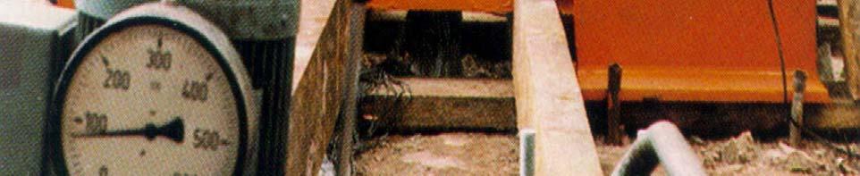
26 MICROPILES - LOAD TESTING - PRINCIPLE OF THE STATIC LOAD TEST In this test, an axial load is applied to a micropile in steps up to a proof load. During each step the load is maintained constant during the time (30 to 60 minutes) Static load test (to failure): Failure load ( Q l ou Q tl ) estimated from geotechnical test Proof load test = Q tmax = 1,5 Q tl (for tension load test) 1,3 Q l (for compression load test) Control test: Maximum load test = 1,3 x Q ELS (Fascicule 62 ) = 1,4 x Q ELS (DTU ) with Q ELS = serviceability limit state load (for permanent loads)
27 MICROPILES - LOAD TESTING - Compression load test program Test load example Load deformation diagram Time
 and Q U (ultimate load) Creep slope / log time Qc Qu Q")
28 MICROPILES - LOAD TESTING - (compression) Creep diagrams Q 3 Q 2 Q 1 t Q 1 From the test: we plot: The creep curves for each load The diagram of the creep speed in log time at 60 min versus load. We determine the two characteristic loads Q C (creep load) and Q U (ultimate load) Creep slope / log time Qc Qu Q


29 MICROPILES - LOAD TESTING - (compression)
30 MICROPILE - CONNECTION CONSIDERATIONS - RECOMMENDED CHECKING Steel characteristics Connections EXAMPLE OF CONNECTION FOR LOAD TRANSFER For pile bridge foundation For slab
31 MICROPILE - CONNECTION CONSIDERATIONS - RECOMMENDED CHECKING Steel characteristics: Some samples could be taken for characteristics verification. The verification of the steel quality is particularly important if re-used tubes are employed. Connections : According to their effective working area, the efficiency of the connection shall be proved by calculation or reference to tests already done. One example of an already completed test is shown on the next slide
32 MICROPILE - CONNECTION CONSIDERATIONS - RECOMMENDED CHECKING Example of connection test


33
34 MICROPILE CONNECTION CONSIDERATIONS - RECOMMENDED CHECKING Example of connection test The result is a failure at the base of the thread at the coupler extremity. It is absolutely necessary to take into account the reduction of the section area for load capacity. This must be done for both tension and compression, and for any kind of connection used.
35 MICROPILE CONNECTION CONSIDERATIONS - EXAMPLES OF CONNECTIONS FOR LOAD TRANSFER Pile ebridge foundation: o Anchor plate with nut on bars Slab connection Anchor plate fixed on tube by coupler
36 MICROPILE - CONNECTION CONSIDERATIONS - Example of anchor plate on bars for pile bridge foundation
37 MICROPILE - CONNECTION CONSIDERATIONS - Example of anchor plate fixed on tube for slab reinforcement connection Paris - cour carrée du Grand Louvre
38 BORED MICROPILES MAURITIUS POWER PLANT - Soil conditions Choice of the solution Foundation structure Phases of execution Micropile head preparation Micropile connection with foundation footing


39 BORED MICROPILES MAURITIUS POWER PLANT - Soil conditions
40 BORED MICROPILES MAURITIUS POWER PLANT - Mauritius power plant foundation Constraints: - Drilling throughout the hard layer of the coral massif - Anchor must be fixed within the basalt over many meters due to the alternatively strong and weathered layers. - necessity of reducing the vibration of the mounting block in service 2 possibilities: ( piles - micropiles ) Piles: - Construction of the rock socket could pose problems in the hard zones. - Risk of loss of bentonite slury within the coral mass. Micropiles: - Possibility of ensuring the uniformity of the fundation soils by injection of the micropile Solution: Micropiles were chosen by expert in soil mecanics
41 BORED MICROPILES MAURITIUS POWER PLANT - Mauritius power plant foundation Micropile difficulties Construction tolerance at the micropile head was required to be less thaen 2 cm Very limited tolerance in the elevation pile head coupling. (This was achieved by coring the concrete slab to centralise the micropile, and to allow the level of the pipe to be maintained in the correct position before the set of the grout. Grouting with IRS method in weathered basalt. (This was achieved by specific phases of grouting)
42 BORED MICROPILES MAURITIUS POWER PLANT - Mauritius power plant foundation
43 BORED MICROPILES MAURITIUS POWER PLANT - Platform preparation
44 BORED MICROPILES MAURITIUS POWER PLANT - POWER PLANT STRUCTURE FOUNDATION micropile drilling with down hole hammer
45 BORED MICROPILES MAURITIUS POWER PLANT - - Execution phases -


46 BORED MICROPILES MAURITIUS POWER PLANT -
47 BORED MICROPILES MAURITIUS POWER PLANT - Breaking out of the pile head
48 BORED MICROPILES MAURITIUS POWER PLANT - Micropile head centraliser
49 BORED MICROPILES MAURITIUS POWER PLANT - Micropile head preparation of the connection for anchor plate Coupler
50 BORED MICROPILES MAURITIUS POWER PLANT - Anchor plate example in place at the top of the micropiles
51 BORED MICOPILES - END - THANK YOU FOR YOUR ATTENTION
INNOVATIVE SLOPE STABILISATION BY USING ISCHEBECK TITAN SOIL NAILS
 Dipl.-Wirt.Ing. Oliver Freudenreich Friedr. Ischebeck GmbH phone: ++49 2333 8305-0 Loher Str. 31 79 fax: ++49 2333 8305-55 e-mail: freudenreich@ischebeck.de D-58256 Ennepetal www.ischebeck.com INNOVATIVE
SAS Micropile Manual. Basic dimensioning and design recommendations. Table of Content:
 SAS Micropile Manual Basic dimensioning and design recommendations Table of Content: Page System Description 2 Load Capacities 2 Minimum Drill Hole Diameter 3 Load Transfer to Ground 4 Corrosion Protection
NPTEL Course GROUND IMPROVEMENT USING MICROPILES
 Lecture 22 NPTEL Course GROUND IMPROVEMENT USING MICROPILES Prof. G L Sivakumar Babu Department of Civil Engineering Indian Institute of Science Bangalore 560012 Email: gls@civil.iisc.ernet.in Contents
SEISMIC RETROFIT OF AN UNDERGROUND RESERVOIR. Robert Small 1, Rob Jameson 2
 ABSTRACT SEISMIC RETROFIT OF AN UNDERGROUND RESERVOIR Robert Small 1, Rob Jameson 2 Seismic Upgrade of the University Mound Reservoir North Basin included 542 micropiles with 1335 KN (300 kip) design capacity
DUCTILE IRON PILES ARE HIGHLY EFFECTIVE, FAST AND VERSATILE MODULAR DRIVEN MICROPILE SYSTEMS
 DUCTILE IRON PILES DUCTILE IRON PILES ARE HIGHLY EFFECTIVE, FAST AND VERSATILE MODULAR DRIVEN MICROPILE SYSTEMS Designed to resist both compression and tension loads in either end-bearing or friction,
Over the last decade, drilled and postgrouted micropile foundations have
 Seismic Design of Micropile Foundation Systems Leo Panian, S.E., and Mike Korolyk, S.E. Over the last decade, drilled and postgrouted micropile foundations have come to be increasingly relied on for resisting
Ground Improvement Prof. G. L. Sivakumar Babu Department of Civil Engineering Indian Institute of Science, Bangalore
 Ground Improvement Prof. G. L. Sivakumar Babu Department of Civil Engineering Indian Institute of Science, Bangalore Module No. # 07 Lecture No. # 22 Micropiles (Refer Slide Time: 00:30) So, we would be
ISM 2007 Toronto, Canada Horst Aschenbroich Dipl. Ing. President & CEO of Con-Tech Systems LTD. Titan Hollow Bar
 Advances in Hollow Thread Bar Micro Pile Installation Techniques, Equipment, Materials, Testing and Monitoring ISM 2007 Toronto, Canada Horst Aschenbroich Dipl. Ing. President & CEO of Con-Tech Systems
FURTHER TECHNICAL INFORMATION IN RELATION TO THE OPERATIONS OF OUR GROUP
 A. TECHNICAL INFORMATION OF OUR FOUNDATION WORKS The major types of our foundation works (with illustrative diagram, where applicable) are set out below: 1. Bored piles 0.80m 3.5m pile shaft By Grabbing
DESIGN-BUILD-TEST PROCESS FOR HIGH CAPACITY MICROPILES: CONSTRUCTION CASE STUDY ON DUTCHESS RAIL TRAIL BRIDGE FOUNDATIONS, POUGHKEEPSIE, NEW YORK
 ABSTRACT DESIGN-BUILD-TEST PROCESS FOR HIGH CAPACITY MICROPILES: CONSTRUCTION CASE STUDY ON DUTCHESS RAIL TRAIL BRIDGE FOUNDATIONS, POUGHKEEPSIE, NEW YORK James Barron 1, P.E., Thomas Hattala 2, P.E.,
Grouting Bilfinger Spezialtiefbau GmbH
 Grouting Bilfinger Spezialtiefbau GmbH Goldsteinstrasse 114 D-60528 Frankfurt Phone: +49 69 6688-345 Fax: +49 69 6688-277 Email: info.spezialtiefbau@bilfinger.com www.foundation-engineering.bilfinger.com
Testing of ground anchorages for a deep excavation retaining system in Bucharest
 XV Danube - European Conference on Geotechnical Engineering (DECGE 2014) H. Brandl & D. Adam (eds.) 9-11 September 2014, Vienna, Austria Paper No. 176 Testing of ground anchorages for a deep excavation
Typical set up for Plate Load test assembly
 Major disadvantages of field tests are Laborious Time consuming Heavy equipment to be carried to field Short duration behavior Plate Load Test Sand Bags Platform for loading Dial Gauge Testing Plate Foundation
Lateral Loads on Micropiles. Thomas Richards Nicholson Construction Company
 Lateral Loads on Micropiles Thomas Richards Nicholson Construction Company Micropile Names Micropile ( DFI & FHWA) = Pin Pile SM ( Nicholson) = Minipile (previously used by Hayward Baker and used in UK)
SECTION NONPRESTRESSED ROCK ANCHORS. 1. Placing drawings. 2. Bar details. 3. Manufacturer s data, and recommendations for grout.
 SECTION 02261 NONPRESTRESSED ROCK ANCHORS PART 1 GENERAL 1.1 THE REQUIREMENT A. The Work in this Section consists of all construction operations relating to designing, furnishing, and installing, complete
ANCHORING WITH BONDED FASTENERS
 ANCHORING WITH BONDED FASTENERS Ronald A. Cook and Robert C. Konz Department of Civil Engineering, University of Florida, USA Abstract Bonded fasteners have been used extensively during the past twenty
Lesson 4. Construction Techniques and Materials. Learning Outcomes. Basic Construction
 Lesson 4 Construction Techniques and Materials schnabel-eng.com Learning Outcomes Describe sequence of construction for a micropile Identify materials used to construct a micropile Describe principle function
Direct Drilled New Micropile TITAN 127/111 for Underpinning Roman Bullring in Barcelona, Spain
 Folie 1 ISM 2007, 8 th International Workshop on Micropiles September 26-30, 2007, Toronto, Canada Direct Drilled New Micropile TITAN 127/111 for Underpinning Roman Bullring in Barcelona, Spain Dipl.-Ing.
EFFICIENCY OF MICROPILE FOR SEISMIC RETROFIT OF FOUNDATION SYSTEM
 EFFICIENCY OF MICROPILE FOR SEISMIC RETROFIT OF FOUNDATION SYSTEM YAMANE TAKASHI, NAKATA YOSHINORI And OTANI YOSHINORI SUMMARY Micropile is drilled and grouted pile with steel pipes which diameters is
The design of soil nailed structures to AS4678
 The design of soil nailed structures to AS4678 Chris Bridges Technical Principal - Geotechnics chris.bridges@smec.com 7 December 2016 1 Presentation Layout Introduction Soil Nailing in AS4678 Design Process
Upon speaking with the representatives with Technical Foundations as well as Walder Foundations, it was determined that:
 As part of our analyses, we have considered the design and construction of the cantilever retaining wall that will be located along the north side of Lucks Lane, between Falling Creek and Gladstone Glen
Lesson 7 & 8 Construction Inspection/ Quality Control (QA/QC) Load Testing. Learning Outcomes. Quality Assurance and Quality Control (QA/QC)
 Load Testing. Learning Outcomes. Quality Assurance and Quality Control (QA/QC)") Lesson 7 & 8 Construction Inspection/ Quality Control (QA/QC) Load Testing schnabel-eng.com Learning Outcomes Identify proper approaches to inspect, monitor and document construction and testing of micropile
Lesson 7 & 8 Construction Inspection/ Quality Control (QA/QC) Load Testing schnabel-eng.com Learning Outcomes Identify proper approaches to inspect, monitor and document construction and testing of micropile
VERTICAL BARRIERS SLURRY TRENCH BARRIERS: excavation equipment. prof. E. Fratalocchi Environmental Geotechnics Waste and polluted sites containment
 VERTICAL BARRIERS SLURRY TRENCH BARRIERS: excavation equipment VERTICAL BARRIERS SLURRY TRENCH BARRIERS: excavation equipment rotary drill hydro-mill backhoe Clamshell + Kelly bar VERTICAL BARRIERS SLURRY
Technical data No. 17/0002 of 22/05/2017
 Hilti Corporation Feldkircherstrasse 100 FL-9494 Schaan Principality of Liechtenstein www.hilti.group Technical data No. 17/0002 of 22/05/2017 General Part Trade name Injection system Hilti HIT-RE 500
COMPARISON OF MALAYSIAN PRACTICE (BS) VERSUS EC7 ON THE DESIGN OF DRIVEN PILE AND BORED PILE FOUNDATIONS UNDER AXIAL COMPRESSION LOAD
 VERSUS EC7 ON THE DESIGN OF DRIVEN PILE AND BORED PILE FOUNDATIONS UNDER AXIAL COMPRESSION LOAD") COMPARISON OF MALAYSIAN PRACTICE (BS) VERSUS EC7 ON THE DESIGN OF DRIVEN PILE AND BORED PILE FOUNDATIONS UNDER AXIAL COMPRESSION LOAD Authors: Ir. Dr. Shiao Yun Wong, Ir. Shafina Sabaruddin and Ir. Yean-Chin
COMPARISON OF MALAYSIAN PRACTICE (BS) VERSUS EC7 ON THE DESIGN OF DRIVEN PILE AND BORED PILE FOUNDATIONS UNDER AXIAL COMPRESSION LOAD Authors: Ir. Dr. Shiao Yun Wong, Ir. Shafina Sabaruddin and Ir. Yean-Chin
STANDARD SPECIFICATION FOR MICROPILE CONSTRUCTION
 Section 67.0 Knoxville, Tennessee March 2013 1. Description STANDARD SPECIFICATION FOR MICROPILE CONSTRUCTION a) This work shall consist of constructing micropiles as shown on the Contract plans in accordance
Micropile Lateral Load Testing in the Charleston, SC Area
 Micropile Lateral Load Testing in the Charleston, SC Area A special thanks to: William B. Wright, PE, Bryan T. Shiver, PE, Kenneth J. Zur, PE, Jackson C. Gosnell, PE, Theodore G. Padgett, PE, and William
RPA Plate Lifting Inserts Technical Manual
 R-Group Finland Oy RPA Plate Lifting Inserts Technical Manual According to Eurocodes, EU Machinery directive 2006/42/EC and VDI/BV-BS 6205 CE Approved 13.7.2017 2 Table of Contents 1 DESCRIPTION OF THE
twenty four foundations and retaining walls Foundation Structural vs. Foundation Design Structural vs. Foundation Design
 ALIED ARCHITECTURAL STRUCTURES: STRUCTURAL ANALYSIS AND SYSTEMS DR. ANNE NICHOLS SRING 2018 lecture twenty four Foundation the engineered interface between the earth and the structure it supports that
Design of Deep Foundations for Slope Stabilization
 Design of Deep Foundations for Slope Stabilization J. Erik Loehr, Ph.D., P.E. University of Missouri Annual Kansas City Geotechnical Conference Overland Park, Kansas April 23, 215 Stability analysis for
Evolution of UK Pile Design to BS EN :2004 (EC7) and the UK National Annex Presentation by:
 and the UK National Annex Presentation by:") Evolution of UK Pile Design to BS EN 1997-1:2004 (EC7) and the UK National Annex Presentation by: Chris Raison BEng MSc CEng MICE MASCE Raison Foster Associates 1 Traditional Pile Design to BS 8004 Ultimate
Evolution of UK Pile Design to BS EN 1997-1:2004 (EC7) and the UK National Annex Presentation by: Chris Raison BEng MSc CEng MICE MASCE Raison Foster Associates 1 Traditional Pile Design to BS 8004 Ultimate
Misan University - College of Engineering Civil Engineering Department
 CHAPTER 2 Soil and Excavations Soil investigation including two phases: surface investigation and subsurface investigation Surface investigation involves making a preliminary judgment about the site s
Pile foundations Introduction
 Engineering manual No. 12 Updated: 06/2018 Pile foundations Introduction Program: Pile, Pile CPT, Pile Group The objective of this engineering manual is to explain the practical use of programs for the
Foundations for infrastructure projects in MENA an approach to reduce risk and construction costs
 Foundations for infrastructure projects in MENA an approach to reduce risk and construction costs Geotechnica ME - 4th & 5th December 2013 Benoît Latapie Senior Geotechnical Engineer WS Atkins & Partners
Soil Mechanics Lateral Earth Pressures page Lateral Earth Pressures in case of inclined ground surface or friction at wall-ground interface
 Soil Mechanics Lateral Earth Pressures page 9 7.6 Lateral Earth Pressures in case of inclined ground surface or friction at wall-ground interface By now, we have considered the wall as perfectly smooth
Specialising in Ground Engineering & Slope Stabilisation
 Specialising in Ground Engineering & Slope Stabilisation Ground Engineering & Slope Stabilisation for the Road, Rail, Construction & Mining Industries Company Profile Warner Company is proudly an Australian
Ching Guan Kee ABSTRACT
 Japanese Geotechnical Society Special Publication The 15th Asian Regional Conference on Soil Mechanics and Geotechnical Engineering Effects of base grouting and deep cement mixing on deep foundation bored
Schnabel Foundation Company
 Micropiles for Roadway Support, Bridge Abutments and Metal Signal Poles on US-158 from US-17B to East of Pasquotank River, in Elizabeth City, NC Schnabel Foundation Company Presenter: Stephen Dimino, P.E.
twenty seven concrete construction: foundation design Foundation Structural vs. Foundation Design Structural vs. Foundation Design
 ARCHITECTURAL STRUCTURES: FORM, BEHAVIOR, AND DESIGN DR. ANNE NICHOLS SRING 2017 lecture twenty seven Foundation the engineered interface between the earth and the structure it supports that transmits
PRESSURE MICROPILES WITH ADJUSTABLE PRELOAD DEVICE
 LIFT AND FIX PRESSURE MICROPILES WITH ADJUSTABLE PRELOAD DEVICE EUROPEAN PATENT FILED OUR COMPANY Novatek provides a range of foundation and flooring repair interventions with a range of new, patented
Offshore pile acceptance using dynamic pile monitoring
 Offshore pile acceptance using dynamic pile monitoring Webster, S. & Givet, R. GRL Engineers, Inc. Charlotte, NC, USA Griffith, A. Saudi Aramco, Dhahran, Saudi Arabia ABSTRACT: Dynamic pile monitoring
twenty six concrete construction: foundation design ELEMENTS OF ARCHITECTURAL STRUCTURES: FORM, BEHAVIOR, AND DESIGN DR. ANNE NICHOLS SPRING 2013
 ELEMENTS OF ARCHITECTURAL STRUCTURES: FORM, BEHAVIOR, AND DESIGN DR. ANNE NICHOLS SPRING 2013 lecture twenty six concrete construction: www.tamu.edu foundation design Foundations 1 Foundation the engineered
MICROPILE LATERAL LOAD TESTING IN CHARLESTON, SOUTH CAROLINA, USA
 MICROPILE LATERAL LOAD TESTING IN CHARLESTON, SOUTH CAROLINA, USA William B. Wright, et. al. 1 ABSTRACT With increasing frequency, micropiles are being used as a foundation solution within the Charleston,
The performance of Single Bore Multiple Anchor trials installed in mixed Moscow soils
 The performance of Single Bore Multiple Anchor trials installed in mixed Moscow soils Dr Devon Mothersille PhD CEng MICE, Managing Director, Single Bore Multiple Anchor Ltd Mr Ali Orkun Bayur BSc MSc,
A. Installer Qualifications: A firm shall have a minimum of five projects successfully constructed in the last ten (10) years.
 years.") NORWOOD HALL EXTERIOR RESTORATION MISSOURI S&T ISSUED FOR BID SECTION 316300 - BORED PILES PART 1 - GENERAL 1.1 SUMMARY A. Section includes resistance piers, couplings, and brackets. 1.2 ACTION SUBMITTALS
NORWOOD HALL EXTERIOR RESTORATION MISSOURI S&T ISSUED FOR BID SECTION 316300 - BORED PILES PART 1 - GENERAL 1.1 SUMMARY A. Section includes resistance piers, couplings, and brackets. 1.2 ACTION SUBMITTALS
GEOTECHNICAL RESISTANCE FACTORS
 Chapter 9 GEOTECHNICAL RESISTANCE FACTORS Final SCDOT GEOTECHNICAL DESIGN MANUAL 9-i Table of Contents Section Page 9.1 Introduction... 9-1 9.2 Soil Properties... 9-2 9.3 Resistance Factors for LRFD Geotechnical
JACK-IN PILE DESIGN MALAYSIAN EXPERIENCE AND DESIGN APPROACH TO EC7
 JACK-IN PILE DESIGN MALAYSIAN EXPERIENCE AND DESIGN APPROACH TO EC7 Chow Chee-Meng & Tan Yean-Chin G&P Geotechnics Sdn Bhd ABSTRACT: Jack-in pile foundation has been successfully adopted in Malaysia since
The requirements for the above tender items are contained in OPSS 942.
 B942 - - OPSS 942 942.1 GENERAL Ground anchors are systems used to transfer tensile loads to soil or rock. These systems comprise prestressing steel tendons, steel anchorages, spacers, centralizers and
Pile Design to BS EN :2004 (EC7) and the National Annex
 and the National Annex") Pile Design to BS EN 1997-1:2004 (EC7) and the National Annex Chris Raison BEng MSc CEng MICE MASCE Raison Foster Associates Tel: 024 7669 1925 Mob: 07974 005990 E-Mail: chris@raisonfoster.co.uk Address:
Pile Design to BS EN 1997-1:2004 (EC7) and the National Annex Chris Raison BEng MSc CEng MICE MASCE Raison Foster Associates Tel: 024 7669 1925 Mob: 07974 005990 E-Mail: chris@raisonfoster.co.uk Address:
MICROPILE FOUNDATIONS FOR RECONSTRUCTION OF HISTORIC LA LOMA BRIDGE IN PASADENA, CALIFORNIA. Casey Garneau 1
 MICROPILE FOUNDATIONS FOR RECONSTRUCTION OF HISTORIC LA LOMA BRIDGE IN PASADENA, CALIFORNIA ABSTRACT: Casey Garneau 1 The historic La Loma Bridge, which crosses the Arroyo Seco in Pasadena, California,
A.Zh.Zhussupbekov Department of Civil Engineering and Engineering Mechanics, Columbia University, New York, USA
 UDK 69.0 A.Zh.Zhussupbekov Department of Civil Engineering and Engineering Mechanics, Columbia University, New York, USA Research of displacement pile and continuous flight auger technologies on construction
Soil Nailing: An Innovative Ground Improvement Technology
 Ground Improvement: Soil Nailing Soil Nailing: An Innovative Ground Improvement Technology Sonjoy Deb, B.Tech, Civil Associate Editor A soil-nailed system is considered as a soil-nailed retaining wall
Page 7-1 Hubbell Power Systems, Inc. All Rights Reserved Copyright 2014 DRAWINGS & RATINGS
 Page 7-1 Hubbell Power Systems, Inc. All Rights Reserved Copyright 2014 PRODUCT DRAWINGS AND RATINGS Section 7 CONTENTS ATLAS RESISTANCE PIERS... 7-3 PIER PIPE SHAFTS... 7-3 REMEDIAL REPAIR BRACKETS for
Bond Strength of Hollow-Core Bar Micropiles
 Missouri University of Science and Technology Scholars' Mine International Conference on Case Histories in Geotechnical Engineering (28) - Sixth International Conference on Case Histories in Geotechnical
Ultra High Capacity and Totally Removable Tiebacks
 FEATURE Ultra High Capacity and Totally Removable Tiebacks by Tony Barley* Director of SBMA Ltd and Mary Ellen Bruce* President of SBMA LLC UK and World Market USA The installation of a multiple of individual
Long-Term Settlement Performance Monitoring, I-15 Reconstruction Project, Salt Lake City, UT. Steven Bartlett, University of Utah
 1 Long-Term Settlement Performance Monitoring, I-15 Reconstruction Project, Salt Lake City, UT Steven Bartlett, University of Utah Roadway Widening (I-15 Project) Salt Lake City Utah, USA 2002 Host of
Earth Mechanics, Inc. Geotechnical & Earthquake Engineering
 DATE: August 31, 2000 Earth Mechanics, Inc. Geotechnical & Earthquake Engineering TECHNICAL MEMORANDUM EMI PROJECT NO: 99-136 PREPARED FOR: COPIES: PREPARED BY: Tayfun Saglam / Parsons Brinckerhoff Juan
Investigation of Hollow Bar Micropiles in Cohesive Soil
 Western University Scholarship@Western Electronic Thesis and Dissertation Repository December 2013 Investigation of Hollow Bar Micropiles in Cohesive Soil Osama F. El Hadi Drbe The University of Western
SPECIAL SPECIFICATION 4401 Prestressed Ground Anchors
 2004 Specifications CSJ 0581-02-121 & 0200-11-100 SPECI SPECIFICATION 4401 Prestressed Ground Anchors 1. Description. Install post-tensioned permanent ground anchors in place, with grouting as required
Chapter 8 Anchoring Structures
 Chapter 8 Anchoring Structures 8-1. General Structural anchors are often used to improve the stability of existing structures but, generally, should not be used as a primary means to stabilize new, large
Case Study. The Challenge. Deep Micropile Installation Under Existing Multistory Building
 The Challenge The Owners of a former warehouse located in the vibrant tech start-up area south of Market St. in San Francisco made the decision to bring the building up to current earthquake standards
TP EA. Product Description. Properties and Benefits. Applications. Reaction Resin Mortar Based on Epoxy Acrylate. Approvals / Certificates:
 Approvals / Certificates: Product Description The TP EA is a 2-component reaction resin mortar based on an epoxy acrylate. This product may be used in combination of a hand-, battery- or pneumatic tool
GEOTECHNICAL INVESTIGATION PROPOSED OUTFALL LOCATION CITY OF MORGAN S POINT DRAINAGE HARRIS COUNTY, TEXAS REPORT NO
 GEOTECHNICAL INVESTIGATION PROPOSED OUTFALL LOCATION CITY OF MORGAN S POINT DRAINAGE HARRIS COUNTY, TEXAS REPORT NO. 1140198001 Reported to: SIRRUS ENGINEERS, INC. Houston, Texas Submitted by: GEOTEST
CHEMICAL /4" 3/8" to 5/8" /8" 3/4" to 1-1/4" 1 10
 194 ASTM A193 GRADE B7 HIGH-STRENGTH CARBON, ZINC PLATED (ASTM B 633 YELLOW DICHROMATE) B7 (AISI 414) anchor rod is supplied with nuts meeting the requirements of ASTM Specification A 194, Grade 2H (ASTM
Post-Grouting of Drilled Shaft Tips on the Sutong Bridge: A Case History
 Post-Grouting of Drilled Shaft Tips on the Sutong Bridge: A Case History Dr. Osama Safaqah 1, P.E., Robert Bittner 2, P.E. & Xigang Zhang 3 1 Project Manager, Ben C. Gerwick, Inc., 20 California Street,
Testing and modelling on an energy absorbing rock bolt
 Testing and modelling on an energy absorbing rock bolt A. Ansell Department of Structural Engineering, Royal Institute of Technology, Stockholm, Sweden Abstract Dynamic loads on underground structures,
HURRICANE SANDY LIMITED REEVALUATION REPORT UNION BEACH, NEW JERSEY DRAFT ENGINEERING APPENDIX SUB APPENDIX B-2 FLOODWALL PILE ANALYSES EAST WALLS
 HURRICANE SANDY LIMITED REEVALUATION REPORT UNION BEACH, NEW JERSEY DRAFT ENGINEERING APPENDIX SUB APPENDIX B-2 FLOODWALL PILE ANALYSES EAST WALLS Revised March 2015 Preliminary Flood Wall Pile Analysis
TORQUE TESTING & INSTALLATION INSPECTION OF DRILLED - IN ANCHORS
 INFORMATION BULLETIN / PUBLIC - BUILDING CODE REFERENCE NO.: LAMC 98.0501 Effective: 04/30/02 DOCUMENT NO. P/BC 2002-092 Revised: Previously Issued As: Guideline #3 TORQUE TESTING & INSTALLATION INSPECTION
BS EN :2004 EN :2004 (E)
") Contents List 1. General 1.1 Scope 1.1.1 Scope of Eurocode 2 1.1.2 Scope of Part 1-1 of Eurocode 2 1.2 Normative references 1.2.1 General reference standards 1.2.2 Other reference standards 1.3 Assumptions
Contents List 1. General 1.1 Scope 1.1.1 Scope of Eurocode 2 1.1.2 Scope of Part 1-1 of Eurocode 2 1.2 Normative references 1.2.1 General reference standards 1.2.2 Other reference standards 1.3 Assumptions
Design and Construction of Drilled Full Displacement Piles using the Penetration Resistance Method
 SUPERPILE 2009 Burlingame, CA Design and Construction of Drilled Full Displacement Piles using the Penetration Resistance Method Peter Faust Malcolm Drilling Company Inc. Alexandria Parking Garage, San
INTERPRETATIONS OF INSTRUMENTED BORED PILES IN KENNY HILL FORMATION
 INTERPRETATIONS OF INSTRUMENTED BORED PILES IN KENNY HILL FORMATION S. S. Liew 1, Y. W. Kowng 2 & S. J. Gan 3 ABSTRACT This paper presents the results of two instrumented bored cast-in-situ test piles
CHAPTER 11: PRESTRESSED CONCRETE
 CHAPTER 11: PRESTRESSED CONCRETE 11.1 GENERAL (1) This chapter gives general guidelines required for the design of prestressed concrete structures or members with CFRM tendons or CFRM tendons in conjunction
NORTHWESTERN UNIVERSITY PROJECT NAME JOB # ISSUED: 03/29/2017
 SECTION 22 0548 - PIPING AND EQUIPMENT PART 1 - GENERAL 1.1 RELATED DOCUMENTS A. Drawings and general provisions of the Contract, including General and Supplementary Conditions and Division 01 Specification
specification sheet for approval
 BMVIT-327.2/6-II/ST2/2 specification sheet for approval (Translation from the German original has not been certified by any authorities) Object of approval: ANP Micropiles SAS 55 with load - bearing s
The use of micropiles as a form of underpinning of existing commercial buildings development of IKEA hall in Gdańsk
 dr inż. Marcin Blockus INGEO Sp. z o.o. Mobile: +48 505 24 38 37 E-mail: blockus@ingeo.com.pl The use of micropiles as a form of underpinning of existing commercial buildings development of IKEA hall in
HIGH CAPACITY MICROPILES IN WEAK DOLOMITIC LIMESTONE FOR CRANE FOUNDATION SUPPORT
 HIGH CAPACITY MICROPILES IN WEAK DOLOMITIC LIMESTONE FOR CRANE FOUNDATION SUPPORT A Case History in Temporary Foundations 12 th International Workshop on Micropiles Krakow, Poland June 14, 2014 Terence
R-Group Finland Oy. RTA, RWTL and RWTS Lifting anchors Design instructions
 R-Group Finland Oy RTA, RWTL and RWTS Lifting anchors Design instructions According to Eurocodes, EU Machinery directive 2006/42/EC and VDI/BV-BS 6205 CE Approved 28.12.2016 2 Table of contents 1 DESCRIPTION
ESR ICC Evaluation Service, Inc. Reissued January 1, 2008 This report is subject to re-examination in one year.
 ESR-1967 Reissued January 1, 2008 This report is subject to re-examination in one year. ICC Evaluation Service, Inc. www.icc-es.org Business/Regional Office # 5360 Workman Mill Road, Whittier, California
SPECIAL SPECIFICATION 4492 Tie Back Anchors
 2004 Specifications CSJ 0504-02-022 SPECI SPECIFICATION 4492 Tie Back Anchors 1. Description. This Item shall govern for the installation of tie-back anchors in place, with grouting as required in accordance
Matrix Helical Anchoring System
 Matrix Helical Anchoring System INNOVATIVE SOLUTIONS FOR PROFESSIONAL MASONRY REINFORCEMENT The uses of Matrix Remedial Ties and Matrix Crack Stitching Bar are both wide and varied and they can be utilised
DESCRIPTION OF THE RD-PILE SYSTEM
 THE RD PILE SYSTEM Hakan Bredenberg, Dr Tech, Bredenberg Teknik, Sweden 1) Sami Eronen, Dr Tech, Rautaruukki Corporation, Finland 2) Mats Larsson, Technical Manager, Ruukki Sverige AB 3) ABSTRACT The RD-
Requirements for Measuring and Pricing of Structural Concrete
 Requirements for Measuring and Pricing of Structural Concrete October 2016 TRANSPORT INFRASTRUCTURE IRELAND (TII) PUBLICATIONS About TII Transport Infrastructure Ireland (TII) is responsible for managing
Comparison of the results of load test done on stone columns and rammed aggregate piers using numerical modeling
 Comparison of the results of load test done on stone columns and rammed aggregate piers using numerical modeling Ece Kurt Civil Eng., M.Sc.& Geoph. Eng., Istanbul, Turkey Berrak Teymur Asst. Prof. Dr.,
Permissible loads of a single anchor in cracked normal concrete (concrete tension zone) of strength class C20/25 ( B25) Permissible tensile load
 of strength class C20/25 ( B25) Permissible tensile load") Injection system FIS VL: Injection mortar FIS VL with Threaded rod FIS A zinc plated steel / stainless steel 1 loads of a single anchor in cracked normal concrete (concrete tension zone) of strength class
Injection system FIS VL: Injection mortar FIS VL with Threaded rod FIS A zinc plated steel / stainless steel 1 loads of a single anchor in cracked normal concrete (concrete tension zone) of strength class
ITEM NN17 - DRILLED SHAFTS ITEM NN17 - DRILLED SHAFTS (LOW OVERHEAD CLEARANCE) ITEM TRIAL SHAFTS
 ITEM TRIAL SHAFTS") DESCRIPTION A. General. This work shall consist of furnishing the materials and installing drilled shafts at the locations, dimensions, and batters shown on the contract plans or where ordered by the Engineer
DESCRIPTION A. General. This work shall consist of furnishing the materials and installing drilled shafts at the locations, dimensions, and batters shown on the contract plans or where ordered by the Engineer
R-Group Finland Oy. REA Lifting Inserts Technical Manual According to Eurocodes, EU Machinery directive 2006/42/EC and VDI/BV-BS 6205 CE Approved
 R-Group Finland Oy REA Lifting Inserts Technical Manual According to Eurocodes, EU Machinery directive 2006/42/EC and VDI/BV-BS 6205 CE Approved 10.2.2017 2 Table of Contents 1 DESCRIPTION OF THE SYSTEM...
SECTION VIBRATION CONTROLS FOR PLUMBING PIPING AND EQUIPMENT
 Page 220548-1 SECTION 220548 - PART 1 - GENERAL 1.1 RELATED DOCUMENTS A. Drawings and general provisions of the Contract, including General and Supplementary Conditions and Division 01 Specification Sections,
Earthquake Reinforcement Using Jet Grouting for a Factory in Operation
 6 th International Conference on Earthquake Geotechnical Engineering 1-4 November 2015 Christchurch, New Zealand Earthquake Reinforcement Using Jet Grouting for a Factory in Operation J. Kawamura 1 ABSTRACT
Challenges of Offshore Geotechnical Engineering
 Challenges of Offshore Geotechnical Engineering OCE 582 - Seabed Geotechnics Professor Kate Moran presented by Ursula Hebinck Overview Content of Paper recent developments in offshore site investigation
Student Services & Classroom Addition SECTION VIBRATION AND SEISMIC CONTROLS FOR ELECTRICAL SYSTEMS
 SECTION 26 05 48 - VIBRATION AND SEISMIC CONTROLS FOR ELECTRICAL SYSTEMS PART 1 - GENERAL 1.1 SUMMARY A. Section includes: 1. Isolation pads. 2. Spring isolators. 3. Restrained spring isolators. 4. Channel
Favorable of grouted micropiles for the load transfer in weak sandy soils
 Favorable of grouted micropiles for the load transfer in weak sandy soils Ahmed Al-Obaidi 1,*, and Ansam Al-Karawi 2 1 Tikrit University, Tikrit, Iraq 2 Cihan University, Erbeil, Iraq Abstract. Micropiles
Learning Outcomes. Background Definitions. Lesson 2 & 3. Definitions, Background, Classification, Applications and Costs
 Lesson 2 & 3 Definitions, Background, Classification, Applications and Costs schnabel-eng.com Learning Outcomes Define a micropile Describe the characteristics, advantages and limitations of micropiles
Modules for Graduate Certificate in Geotechnical Engineering
 Modules for Graduate Certificate in Geotechnical Engineering * SkillsFuture credit (available for Singapore Citizens, subject to approval) ^ SkillsFuture Singapore (SSG) subsidy available for eligible
BAUER DUKI Pile System
 BAUER DUKI Pile System The Bauer Duki Pile System How to install a simple, economic and safe foundation system Skin friction piles (grouted) 2 End-bearing piles (non grouted) The Bauer DUKI Pile System
CONTINUOUS FLIGHT AUGER (CFA) PILES QC/QA PROCEDURES. Preferred QC/QA Procedures
 PILES QC/QA PROCEDURES. Preferred QC/QA Procedures") Preferred QC/QA Procedures The Federal Highway Administration (FHWA) has provided QC/QA guidance for this technology as noted below. The reference document also contains information about construction
Preferred QC/QA Procedures The Federal Highway Administration (FHWA) has provided QC/QA guidance for this technology as noted below. The reference document also contains information about construction
Bi-Directional Static Load Testing of Driven Piles
 Bi-Directional Static Load Testing of Driven Piles Paul J. Bullock, PhD Fugro Consultants Inc. Loadtest Bi-Directional Osterberg Cell Testing Specialized jack in pile uses bearing to mobilize side shear
Case History: Value Engineering of Driven H-Piles for Slope Stability on the Missouri River
 DEEP FOUNDATIONS 207 Case History: Value Engineering of Driven H-Piles for Slope Stability on the Missouri River W. Robert Thompson, III, 1 M.ASCE, P.E., Jeffrey R. Hill, 2 M.ASCE, P.E., and J. Erik Loehr,
Estimation of in-situ water content, void ratio, dry unit weight and porosity using CPT for saturated sands
 Barounis, N. & Philpot, J. (217) Estimation of in-situ water content, void ratio, dry unit weight and porosity using CPT for saturated sands Proc. 2 th NZGS Geotechnical Symposium. Eds. GJ Alexander &
Earth Retention Systems
 haywardbaker.com Earth Retention Systems Mark W. Goodsell, P.E., D.GE Senior Engineer 2 Earth Retention Systems Focus of Presentation Different Types and Purposes of Earth Retention Systems Design Considerations/Geotechnical
SECTION VIBRATION AND SEISMIC CONTROLS FOR ELECTRICAL SYSTEMS
 SECTION 260548 - VIBRATION AND SEISMIC CONTROLS FOR ELECTRICAL SYSTEMS PART 1 - GENERAL 1.1 SUMMARY A. Section includes: 1. Isolation pads. 2. Spring isolators. 3. Restrained spring isolators. 4. Channel