SECTION 8 WATER SUPPLY SYSTEMS
|
|
|
- Christine Bailey
- 6 years ago
- Views:
Transcription
1 SECTION 8 WATER SUPPLY SYSTEMS Contents Page 8-1 INTRODUCTION INTENT OF WATER SYSTEM IMPROVEMENT STANDARDS DEFINITIONS APPLICABLE STANDARDS IMPROVEMENT AND LANDSCAPE PLAN SUBMITTAL APPROVAL OF IMPROVEMENT AND LANDSCAPE PLANS IMPROVEMENT PLAN REVISION CONNECTION PERMITS AND FEES WATER SUPPLY QUALITY WATER SUPPLY PRESSURE WATER DEMAND FIRE FLOWS WELLS, TREATMENT PLANT AND STORAGE FACILITY DESIGN TRANSMISSION MAIN DESIGN... 9 A. Transmission Main Design Plan Requirements... 9 B. Transmission Main Location C. Transmission Main Layout and Sizing D. Transmission Main Pipe Restraint E. Transmission Main Pipe Type and Pipe Deflection F. C200 Steel and C303 Concrete Cylinder Transmission Mains G. Transmission Main Cathodic Protection Systems H. Transmission Main Water System Appurtenances DISTRIBUTION MAIN DESIGN A. Distribution Main Design Plan Requirements B. Distribution Main Location C. Distribution Main Layout and Sizing D. Distribution Main Pipe Restraint E. Distribution Main Pipe Type and Pipe Deflection F. Abandonment of Existing Distribution Mains, Services, and Appurtenances DISTRIBUTION MAIN WATER SYSTEM APPURTENANCES A. Valves B. Fire Hydrants and End-of-Line Blow-off Assemblies C. Water Service Lines D. Water Meters E. Fire Service Double Check Detector Valves F. Back Flow Devices G. Air Release/Vacuum Valve Assemblies H. Blow-off Valves I. Locating Wire Stations J. Water Sample Stations... 24
2 8-17 RECYCLED WATER TRANSMISSION AND DISTRIBUTION MAIN DESIGN RAW WATER TRANSMISSION MAIN DESIGN RECORD PLANS... 25
3 SECTION 8 WATER SUPPLY SYSTEMS 8-1 INTRODUCTION: These Improvement Standards govern the design of all water systems intended for operation and maintenance by the County of Sacramento and the Sacramento County Water Agency. The County of Sacramento provides wholesale and retail water service to certain areas through the Sacramento County Water Agency. 8-2 INTENT OF WATER SYSTEM IMPROVEMENT STANDARDS: The intent of these water system Improvement Standards is to provide a water system that reliably and safely conveys water at a reasonable capital cost and to provide water systems that minimize operation and maintenance costs. 8-3 DEFINITIONS: When the following terms or titles are used in these water system Improvement Standards or in any document or instrument where these Standards govern, the intent and meaning shall be as herein defined: AWWA: American Water Works Association. SIPS: Site Improvement and Permits Section of the County Engineering Division of the Office of Development and Code Services. Non-potable Water: water that does not meet the standards for drinking water but does not originate from sewage. For County purposes considered as a type of recycled water. Potable Water: drinkable water. Raw Water: ground water or surface water, prior to treatment. Reclaimed Water: tertiary treated water that meets the requirements of Title 22, Chapter 3 Regulations of the California Administrative Code. Recycled Water: non-potable or reclaimed water. SCWA: Sacramento County Water Agency. Water Agency: Sacramento County Water Agency. Water Supply: Planning, Development, Design, and Water Operation and Maintenance sections of the Department of Water Resources of the County of Sacramento. Water System: potable water, raw water, and recycled water systems. 8-4 APPLICABLE STANDARDS: Items not addressed in these Improvement Standards shall be designed in accordance with accepted engineering practices and in accordance with the latest editions of the following: Standard Construction Specifications of the County of Sacramento. 8-1
4 Title 4 and Title 5 of the Sacramento County Water Agency Code where applicable within zones of the Water Agency. Laws, codes, and standards of the State of California relating to domestic water supply. Rules and Regulations for Recycled Water Use and Distribution, County of Sacramento. Laws, codes, and regulations of the State of California relating to water use, conservation, and water efficient landscapes. Title 22, Chapter 3 of the Regulations of the California Administrative Code. American Water Works Association Standards and Manuals of Water Supply Practice. California Uniform Fire Code. 8-5 IMPROVEMENT AND LANDSCAPE PLAN SUBMITTAL: Improvement plans for developments that will be served retail or wholesale water by the Water Agency shall be reviewed by Water Supply. Improvement plans shall meet the requirements of Section 2 General Requirements, of these Improvement Standards. The initial submittal of improvement plans shall be made to SIPS in accordance with the table below. SIPS will route plans to Water Supply. Subsequent resubmittals of improvement plans for projects in the unincorporated County area shall be delivered to SIPS. Subsequent resubmittals of improvement plans for projects in a City shall be delivered directly to Water Supply. PDF s may be submitted in lieu of hard copies for the plan-checking phase. Landscape plans for developments that will be served retail or wholesale water by the Water Agency, either potable or recycled, shall be reviewed by Water Supply and by the County or City department having jurisdiction. The following types of landscape projects shall be submitted for review and approval: parks, landscape corridors, residential street frontage, commercial, industrial, apartment, school, and street improvement projects. Irrigation systems required by Water Supply to use recycled water shall comply with all requirements of the latest edition of Rules and Regulations for Recycled Water Use and Distribution, County of Sacramento. Landscape plans shall be formatted for 22-inch by 34-inch or 24- inch by 36-inch paper sizes. Two complete sets of the initial submittal of landscape plans associated with an improvement plan, for which there is an existing charge account established at SIPS for the improvement plan, shall be submitted directly to Water Supply as well as subsequent resubmittals, and the charges for plan checking and inspection will be charged to the improvement plan account. The initial submittal of all other landscape plans shall be made to SIPS. After establishment of a charge account for plan checking and applicable construction inspection, SIPS will route the plans to Water Supply. PDF s may be submitted in lieu of hard copies for the plan-checking phase. 8-2
5 DELIVERY OF PLANS (Delivery Location / Number of Sets Required By Water Supply) INITIAL PLAN SUBMITTAL PLAN RE- SUBMITTAL APPROVED PLAN APPROVED PLAN REVISION RECORD PLAN Deliver To: (Quantity) Deliver To: (Quantity) Deliver To: (Quantity) Deliver To: (Quantity) Deliver To: (Quantity) IMPROVEMENT PLANS PROJECTS IN THE UNINCORPORATED COUNTY AREA PROJECTS IN A CITY SIPS (2 sets or PDF s*) SIPS** (2 sets or PDF s *) SIPS (2 sets or PDF s *) Water Supply (2 sets or PDF s) SIPS (2 sets*) SIPS** (2 sets*) SIPS (2 sets*) SIPS** (2 sets*) Supervising County Inspector (2 sets*) Supervising County Inspector (2 sets*) LANDSCAPE PLANS*** ASSOCIATED WITH AN IMPROVEMENT PLAN THAT HAS AN ACTIVE SIPS CHARGE ACCOUNT OTHER LANDSCAPE PLANS Water Supply (2 sets or PDF s) SIPS** (2 sets or PDF s) Water Supply (2 sets or PDF s) Water Supply (4 sets) Water Supply (4 sets) Supervising County Inspector (2 sets*) * The total number of sets required for submission will be greater due to the sets required by other County departments having jurisdiction. Contact the receiving office to determine the total number of required sets for submission. ** SIPS services are limited to (1) establishment of the charge account for plan checking and construction inspection, and (2) distribution of the delivered plans to the applicable County departments. *** Delivery location and number of sets for landscape plans that contain sewer service or major drainage, or that are subject to County Drainage fees or review by other County departments, shall be in accordance with Improvement Plans above. A completed SCWA Water Service Request and Cross Connection Control Questionnaire shall be submitted to Water Supply for all projects except singlefamily residential projects. A separate questionnaire shall be submitted for each building. Facility design information shall be provided as required on the form, including design flows for consumptive use and fire sprinklers. The questionnaire shall be stamped by a licensed engineer or a licensed architect. Completed questionnaires shall be included with the first or second plan submittal, and shall 8-3
6 be approved prior to approval of a plan. Water Supply will provide the questionnaire upon request. 8-6 APPROVAL OF IMPROVEMENT AND LANDSCAPE PLANS: All improvement and landscape plans to be served by the Water Agency shall be approved and signed by an authorized representative of the Water Agency. A. Improvement Plans -- The following shall occur before the improvement plans can be approved: All comments made by Water Supply to the improvement plans shall be addressed. Two sets of landscape plans shall be submitted to Water Supply. Alternatively, in lieu of submission of landscape plans, a letter and diagram prepared and stamped by a licensed landscape architect shall be submitted with the following information: (1) the water demand and meter sizes, with calculations, (2) a diagram showing the boundaries of the area to be served, street crossing sleeves, and the location of service connections, water meters, and reduced pressure principle backflow devices, (3) a delineation of areas to be served by potable and/or recycled water. It is essential that meters are sized and located properly prior to improvement plan signing to preclude the need to relocate meters in the future. Irrigation services, meters, and backflow devices shall be shown on the improvement plans. The Fire Department shall approve and sign the improvement plans. The location of all wells in use and all abandoned wells shall be shown on the grading plan. A note shall be placed on the plans indicating that wells shall be properly destroyed in accordance with the requirements of the Sacramento County Environmental Management Department. The note shall also instruct the contractor to call Sacramento County Environmental Management Department at for inspection of the well destruction. If the project is within the water supply service area of the Water Agency, the applicable water development fees shall be paid. Development fees for Zone 40 and Zone 50 shall be in accordance with Schedule A of Title 4 of the Sacramento County Water Agency Code and with the development fee programs in effect for sub-areas within Zone 40. Fees shall be paid at SIPS. Well and treatment plant sites shall be approved by Water Supply. Purchase agreements for well, treatment plant, and storage sites, where required by the conditions of approval, shall be executed by the property owners and delivered to Water Supply. Well site and 8-4
7 treatment plant site assessment reports shall be submitted to Water Supply. Water easements shall be approved by Water Supply and County Real Estate Division. If documentation is required by Water Supply to substantiate an easement signer s authority to convey easements on behalf of a property owner, the documentation shall be provided and approved. B. Landscape Plans -- Water Supply will review landscape plans for the following items: The proper water delivery pressure shall be stated, starting at the transmission main, in accordance with Section 8-10 of these Standards. The location and size of water services, meters, and backflow devices shall match the approved improvement plans. An irrigation schedule shall be included in the plans listing the following minimum information: all control valves shown on the plans, the demand at each control valve in gpm, and the run time of each control valve in minutes on the maximum day. The controllers shall be set so that flows do not exceed the maximum allowable flow for the meter size stipulated in Section 8-16.D. No trees shall be planted within 8 feet of a water main, service, or appurtenance, measured centerline to centerline. Landscape plans using recycled water for the water source shall meet all requirements of the latest edition of Rules and Regulations for Recycled Water Use and Distribution, County of Sacramento. A signature block for the Water Agency shall be provided on a landscape plan with the label Approval for SCWA Water Fees and Meter Size Only, Sacramento County Water Agency, and a space for the date. If a landscape plan includes recycled water irrigation, the signature block for the Water Agency shall instead be provided with the label Approval for Fees, Meter Size, and Recycled Water Requirements Only, Sacramento County Water Agency, and a space for the date. The SIPS charge account order number for plan checking and applicable construction inspection shall be listed on the cover sheet. Landscaping projects subject to these Improvement Standards shall not be constructed prior to plan approval by the Water Agency. C. Delivery of Approved Improvement and Landscape Plans -- After approvals have been obtained and prior to the start of construction, plan 8-5
8 sets shall be delivered to the location and in the quantity listed in the table above. Of the sets delivered to SIPS, SIPS will route two sets to Water Supply. 8-7 IMPROVEMENT PLAN REVISION: All plan revisions that affect a water system to be maintained and operated by the Water Agency shall be approved and signed by an authorized representative of Water Supply prior to being approved by SIPS or a City and prior to construction of the revision. Revisions shall normally be made using hand markups on the originals. If the nature of a revision is such that hand markups would result in poor legibility, a replacement drawing may be added to the set; in this case, the original approved drawing shall remain in the set with an X through it. After approvals have been obtained and prior to the start of construction, copies shall be delivered to the location and in the quantity listed in the table above. Of the sets delivered to SIPS, SIPS will route two sets to Water Supply. 8-8 CONNECTION PERMITS AND FEES: A water connection permit shall be obtained for each connection to the water system. Contact Water Supply for information concerning Water Agency fees. 8-9 WATER SUPPLY QUALITY: The quality of the potable water supplied by the Water Agency will conform to the Environmental Protection Agency Drinking Water Act, and the State of California Drinking Water Standards WATER SUPPLY PRESSURE: Water supply pressures shall be designed as follows: A. Potable Water -- Normal operating pressure in water transmission mains shall be 40 psi minimum to 90 psi maximum. Normal operating pressure in water distribution mains shall be 35 psi minimum to 90 psi maximum. The minimum pressure for domestic services, fire services, and irrigation services shall be 35 psi at the point where the service line connects to a distribution main. During periods of maximum day domestic demand plus fire demand, the pressure shall not be less than 20 psi at the location of the fire flow and no less than 10 psi elsewhere in the distribution system. B. Recycled Water -- Recycled water distribution systems shall be designed to maintain a minimum pressure of 40 psi at the service connection WATER DEMAND: For the design of water distribution systems serving single family residential areas, assume the water demand is 1 gallon per minute per 8-6
9 residential connection (maximum day demand) plus fire flow. For the design of water distribution systems serving commercial areas, water demand shall be determined in accordance with industrial standards and in consultation with the Water Agency FIRE FLOWS: Required fire flows shall be determined by the adopted California Uniform Fire Code, the fire protection district having jurisdiction, and the County of Sacramento. Water distribution systems shall be designed to provide max day demand plus the required fire flow to each hydrant while maintaining 20 psi or greater residual pressure at the hydrant. For all projects, a note shall be placed on the water plan stating the design fire flow for the distribution system. The water distribution system for single family residential water areas is designed for 1,500 gpm. This will meet requirements for homes up to 3,600 square feet of combustible area, including garages and porches. Homes larger than 3,600 square feet of combustible area are a special condition and may require increased fire flows with larger mains. Required fire flows are 1,750 gpm for homes from 3,600 to 4,800 square feet of combustible area and 2,000 gpm for homes from 4,800 to 6,200 square feet or more of combustible area, or as required by the local Fire Department. The minimum fire flow required by the adopted California Uniform Fire Code for commercial/industrial water systems is 1,500 gpm. For all new commercial/industrial projects the Water Agency shall require a distribution system designed for 3,000 gpm. Larger buildings or projects may require fire flows up to 4,000 gpm and may require water system upgrades or private supplemental water supplies WELLS, TREATMENT PLANT AND STORAGE FACILITY DESIGN: Water Supply will either design or provide design oversight for the construction of wells, treatment plants, booster pumping plants, and storage facilities for Water Agency use. In general, all developments shall have a minimum of two sources of water. If adequate elevated or ground level storage is provided, a single source of water system may be acceptable upon approval by Water Supply and the local fire district. Sites for the above water facilities shall be provided when required by the conditions of approval for a project. Sites for wells shall meet the following criteria: 8-7
10 1. Sites shall meet the requirements of the Environmental Health Division of the County Environmental Management Department, and the Division of Drinking Water of the State Water Resources Control Board. 2. Sites shall conform to the requirements of Standard Drawing Special provisions in the form of prohibitions, restrictions, and special construction may be required on adjacent properties and improvements. 3. In general, a minimum horizontal separation of 1000 feet shall be maintained between existing wells of any type and new municipal wells. The Water Agency may require a greater minimum horizontal separation in certain aquifers. If less separation is proposed, a hydrogeologic study shall be provided to evaluate the influence on and by other wells. The study shall be approved by Water Supply. 4. Sites shall be located to minimize the length of raw water mains. 5. Sites shall abut a paved street with a minimum 30 feet frontage. 6. Where possible, well sites shall be bordered by open space, such as parks or school sites. If such open space does not exist, well sites shall be bordered by commercial space. 7. Well sites shall be fenced with 6-foot split face masonry walls, other fencing solutions are subject to the approval of the Director. 8. Sites shall be provided a water service and a storm drain stub sized for the well capacity. The applicant shall provide Water Supply with information necessary to verify that proposed well sites and treatment plant sites comply with the setbacks recommended by the Environmental Health Division of the County Environmental Management Department, and the Division of Drinking Water of the State Water Resources Control Board. The information shall consist of copies of existing environmental site assessment reports for all properties within 1000 feet of proposed well sites and treatment plant sites. If reports are not available, the applicant shall procure the services of a qualified firm, acceptable to Water Supply, to prepare a site assessment report providing the necessary information. A preliminary hydro-geologic and sanitary assessment, including exploratory test hole drilling and evaluation, shall be performed for each proposed well site. If the results are not acceptable to Water Supply, alternate well site locations shall be provided and evaluated as above until acceptable results are obtained. When well sites are required by the conditions of approval, improvement plans shall not be approved until acceptable results are obtained and acceptable sites provided for all 8-8
11 well sites. Sufficient time shall be provided for this process to be completed prior to plan approval TRANSMISSION MAIN DESIGN: Technical specifications and details for water transmission mains will be prepared by Water Supply and given to the consultant to be included with the improvement plans. Transmission mains shall be designed to provide a minimum of 3,000 gpm at distribution main connection points. In order to minimize connections to the transmission main, distribution main connections to the transmission main shall be provided at one-quarter mile intervals beginning one-eighth mile from section corners or arterial intersections as approved by Water Supply. Distribution main connections shall be 12 inches in diameter, with valves, and shall extend to the edge of pavement. A minimum of one valve shall be located on the transmission main at distribution main connection points. Under no circumstances shall fire hydrants or water services be directly connected to a transmission main. If hydrants or services are needed, a distribution main shall be included on the improvement plan. A. Transmission Main Design Plan Requirements: 1. The transmission mains shall be shown in full in plan and profile views, including valves, air relief/vacuum valve assemblies, blowoff assemblies, all other appurtenances, and restrained joint lengths. Normally, restrained joint lengths shall be shown on the profile. 2. A water plan sheet shall be included as part of the improvement plans, showing locations of valves, fire hydrants, existing water lines, air release/vacuum valves, blow off valves, water services, and water quality sampling stations. The water plan shall also indicate driveways, electroliers, and storm drain inlets. The scale of the water plan shall normally be 1 inch = less than or equal to 100 feet and as necessary to fit the water plan onto a single sheet and legibly show the water facilities and call outs. If water facilities scaled at 1 inch = 100 feet cannot fit onto a single sheet, the water plan may be shown on multiple sheets. 3. Details of distribution mains crossing other utilities or unusual alignments shall be provided if deemed necessary by Water Supply. 4. Stationing and elevations for all fittings, hydrants, valves, air release/vacuum valves, end-of-line blow-offs, temporary blowoffs, in-line blow-off valves and locating wire stations shall be 8-9
12 called-out in the profile view of the improvement plan sheets. Stationing for restrained joint lengths shall be called out. Elevations shall be called-out at all changes in pipe elevation. Certain standard drawings require installation of gate valves as part of the construction of a water transmission main appurtenance. Each of those gate valves shall be shown on the plan view with the use of the correct valve symbol. 5. Water construction notes shall be numbered. The number of a note shall not vary within a plan set. The notes applicable to a drawing shall be listed on that drawing. The water plan shall include a complete list of all water construction notes. B. Transmission Main Location -- All transmission mains shall be installed within public rights-of-way or water easements. 1. The water transmission main shall be located on the north or west side of a street. The water transmission main may be located at a minimum of 4 feet from the lip of gutter. The transmission main and valve actuators shall be located so that the valve boxes will be located in the center of a traffic lane or on traffic lane lines. A deviation from these criteria may be allowed if approved by Water Supply in consultation with other affected utility providers. 2. Water transmission mains shall not be located within landscape corridors or medians, unless approved by Water Supply as a result of irresolvable conflicts with other utilities. 3. Water Transmission Main Separation Separation shall comply with Section Water Main Separation of the California Code of Regulations. Separation may vary if approved by both the State Water Resources Control Board and by Water Supply. 4. Normal minimum cover under roadways shall be 48 inches and as necessary to provide (a.) a minimum of 8 vertical inches between the top of the main and the bottom of the street subgrade scarification zone, and (b.) sufficient main depth for air release/vacuum valve lines to be installed beneath the street subgrade scarification zone. A minimum cover of 36 inches for C900/C905 PVC pipe, C200 steel pipe, and C303 concrete cylinder pipe, and 30 inches for C151 ductile iron pipe may be allowed in special circumstances if approved by Water Supply. Minimum cover depth shall be measured from gutter flow-line (existing, new, or future) to top of pipe. 8-10
13 5. Minimum cover in open fields shall be 60 inches for C900/C905 PVC pipe and C303 concrete cylinder pipe, and 48 inches for C151 ductile iron pipe. 6. Transmission mains shall not be located under portland cement concrete pavements unless approved by Water Supply. If it is necessary to locate a transmission main under a decorative AC pavement, valves and fittings shall be located outside of the decorative area and pipe in the decorative area shall be restrained Class 350 ductile iron. 7. Railroad undercrossings shall normally be in steel casings with cathodic protection on the casing. C. Transmission Main Layout and Sizing -- The transmission main system location and size shall conform to the master water supply plans of the Water Agency. The maximum degree of bend for elbow fittings shall be 45 degrees for horizontal bends and 22.5 degrees for vertical bends, unless approved by Water Supply. D. Transmission Main Pipe Restraint -- Pipes shall be restrained from movement as a result of thrust on the fittings and valves of the water transmission main system. Thrust restraint shall be provided at all valves, bends, reducers, tees, crosses, and dead ends. Restrained Joints -- Restrained joints shall be used to resist thrust at fittings and valves 14 inches in diameter and larger, at valves 12 inches in diameter and less, and at fittings 12 inches in diameter and less in thrust configurations not covered in Standard Drawing 8-3A. If the type of pipe within a restrained joint length is restricted to ductile iron or to another specific pipe type, it shall be called out. The Standard Drawings for lateral water appurtenances include the necessary requirements for joint restraint and pipe type for the construction of the appurtenance. Water distribution main stub-outs for future extension that are installed with water transmission mains shall be restrained over the full length of the stub. E. Transmission Main Pipe Type and Pipe Deflection -- Pipes 18 inches and less in diameter may be AWWA C151 ductile iron or AWWA C900/C905 polyvinyl chloride. Pipes 20 through 30 inches in diameter shall be AWWA C151 ductile iron. Pipes 36 through 60 inches in diameter shall be AWWA C151 ductile iron unless approved by the Water Agency. 8-11
14 Pipes 36 through 60 inches in diameter may be AWWA C200 steel pipe or AWWA C303 concrete cylinder pipe if the use of the transmission main is such that it will not be subject to future tapping or cut-in s as determined by the Water Agency. Pipes 64 inches and more in diameter shall be AWWA C200 steel pipe or AWWA C303 concrete cylinder pipe. For ductile iron pipe without restrained joints, deflection at joints shall not exceed 2.5 degrees for 36-inch and smaller pipe and 2.0 degrees for 42- inch and larger pipe. A fitting shall be used if joint deflections exceed these limits. For ductile iron pipe with restrained joints, deflection at joints shall not exceed: 2.5 degrees for 12-inch and smaller pipe, 2.0 degrees for 16-inch and 18-inch pipe, 1.25 degrees for 20-inch and 24-inch pipe, 1.0 degrees for 30-inch pipe, 0.75 degrees for 36-inch pipe, and 0.25 degrees for 42- inch and larger pipe. A fitting shall be used if joint deflections exceed these limits. Joint deflection of polyvinyl chloride pipe is not allowed. Bending of polyvinyl chloride pipe shall not exceed the limits described in Standard Drawing 8-9B. F. C200 Steel and C303 Concrete Cylinder Transmission Mains -- Improvement plans and specifications shall require the contractor to hire an independent testing firm (subject to approval by the Water Agency) to provide certified welding inspections, confined space inspections, and the specialty inspections listed below for the project. The scope of inspection shall be (a) delivery acceptance inspection of all pipe and fittings, (b) inspection of all field welds with the use of magnaflux or penetrating dye method, and (c) inspection and testing of all exterior coatings and patching prior to backfilling and inspection and testing of all interior linings, patching, and pipe cleaning after completion of backfilling. G. Transmission Main Cathodic Protection Systems -- Cathodic protection systems shall not be provided unless required by Water Supply. Cathodic protection systems shall be designed with a 50-year life. Buried lateral cable runs shall be in concrete-encased conduit with a minimum of 48 inches of cover. Test stations shall be located in non-traffic areas and shall be extra heavy duty, vandal resistant, and tamper resistant. The location of all anode beds, lateral cable runs, and test stations shall be shown to scale on the civil plan and profile sheets and shall be called out by station and offset from road centerline on either the plan view or profile. 8-12
15 H. Transmission Main Water System Appurtenances -- Transmission main appurtenance requirements on the improvement plans shall be as follows: 1. Valves shall be spaced no greater than 1300 feet apart and shall be located so that any section of main can be shut down without going to more than three locations to close valves. Normally, three valves shall be placed where mains cross and two valves where mains tee. Each section of pipeline between crosses or tees shall have a minimum of one valve. Valves at intersections shall be located within the curb returns and set as close to minimum pipe depth as possible. Valves shall be placed on the end of temporary transmission main dead ends that are longer than 330 feet. On temporary dead ends shorter than 330 feet, valves shall be placed at the tee or cross. Valves 8 inches in diameter and smaller shall be gate valves. Ten-inch valves may be gate or butterfly valves. Valves larger than 10 inches in diameter shall be butterfly valves. Butterfly valve symbols shall indicate on which side of the pipe to install the offset right-angle gear drive valve operator. Operators shall be located as near as possible to center of lanes or lane lines. No more than one butterfly valve operator shall be located in a single quadrant of a tee or cross. 2. Air release/vacuum valve assemblies shall be required at high points on the transmission main as determined by Water Supply. Transmission mains shall require a 2-inch air release vacuum valve. See Standard Drawing 8-14B for specifications and typical installation details. In streets with roadside ditches, provide profile views of ARV lines and boxes. ARV boxes shall be located beyond the ditch. ARV lines shall not daylight in the ditch crossing. 3. Temporary blow-offs shall be provided on stub-outs. Temporary blow-offs may be 2 inches in diameter for mains up to 24 inches in diameter and 3 inches in diameter for mains larger than 24 inches in diameter, subject to approval by Water Supply. 4. Permanent blow-offs shall be provided at dead ends. Permanent blow-offs shall be 4 inches in diameter for lines up to 24 inches in diameter and 6 inches in diameter for lines larger than 24 inches in diameter. 5. In-line blow-off valves shall be required at low points on the water transmission main as determined by Water Supply. In-line blowoff valves shall be 4 inches in diameter for water lines up to
16 inches in diameter and 6 inches in diameter for water lines larger than 24 inches in diameter. In streets with roadside ditches, provide profile views of blow-off lines and boxes. When possible, blow-off valves and boxes shall be located beyond the ditch. 6. Locating wire stations shall be placed on transmission mains when the distance between valves and/or permanent and in-line blowoffs exceeds 600 feet. See Standard Drawing 8-4B for specifications and typical installation details DISTRIBUTION MAIN DESIGN: In general, water distribution systems shall be looped, with two points of connection to water sources, separated by a minimum of one valve and an adequate separation distance approved by Water Supply. Sizing of distribution mains shall be such that the normal pressures stated in Section 8-10 and the minimum requirements stated below for distribution main spacing and sizing are attained. The Hazen-Williams formula shall be used in the hydraulic study of the system, using a C value of 125 for cement-lined pipe, polyvinyl chloride pipe, and ductile iron pipe. Velocity in distribution mains shall not exceed 7 feet per second at peak hour or 10 feet per second conveying fire flow. Unit head loss shall not exceed 5 feet per 1,000 feet. The unit head loss does not apply to fire flow. A Hardy-Cross hydraulic analysis of any proposed distribution system shall be supplied to Water Supply. The analysis shall comply with the requirements of Sections 8-10, 8-11, and A. Distribution Main Design Plan Requirements: 1. All public distribution mains, including those on commercial and apartment projects, shall be shown in plan and profile. Profile sheets shall include the portion of the plan area being profiled, placed above the profile and vertically aligned with the profile. Restrained joint lengths shall be shown. Normally, restrained joint lengths shall be shown on the profile. Stub-outs for future extension shall be shown in plan and profile. The profile for stubouts may be omitted if (a) the design profile is straight, (b) finish grades over stub length are provided, and (c) there are no crossings, ditches, or embankments. 2. A water plan sheet shall be included as part of the improvement plans, showing locations of valves, fire hydrants, existing water 8-14
17 lines, air release/vacuum valves, blow off valves, water services, and water quality sampling stations. The water plan shall also indicate driveways, electroliers, and storm drain inlets. The scale of the water plan shall normally be 1 inch = less than or equal to 100 feet and as necessary to fit the water plan onto a single sheet and legibly show the water facilities and call outs. If water facilities scaled at 1 inch = 100 feet cannot fit onto a single sheet, the water plan may be shown on multiple sheets. 3. Details of distribution mains crossing other utilities or unusual alignments shall be provided if deemed necessary by Water Supply. 4. Stationing for all fittings, shut off valves, hydrants, air release/vacuum valves, in line blow-off valves, and end-of-main blow-off valves shall be called-out in the profile view of the improvement plan sheets. Stationing for restrained joint lengths shall be called out. Elevations shall be called-out at all changes in pipe elevation. With the exception of single-family residential services, the size of all connections to the main and the specific fitting required shall be called out on the profile. Certain standard drawings require installation of gate valves as part of the construction of a water appurtenance. Each of those gate valves shall be shown on the plan view with the use of the correct valve symbol, except that above-ground gate valves in backflow prevention assemblies shall not be shown. 5. Commercial, industrial, and multi-family improvement plans with a water easement shall have a note that states, Utilities shall not be located within water easement(s) except for crossings made as close to perpendicular to the water main as practical. 6. All plans shall include the most recent version of the standard SCWA Water Notes. The most recent version of the standard SCWA Recycled, Raw, and Landscape Water notes shall also be included as necessary. Water Supply will provide the notes upon request. 7. Water construction notes shall be numbered. The number of a note shall not vary within a plan set. The notes applicable to a drawing shall be listed on that drawing. The water plan shall include a complete list of all water construction notes. B. Distribution Main Location -- All water distribution mains shall be installed within public rights-of-way or easements. 8-15
18 1. The centerline of the water distribution main shall be located 3 feet from the lip of the gutter on the northerly or westerly side of the street. A deviation from these criteria may be allowed if approved by Water Supply in consultation with other affected utility providers. If it should be necessary because of existing improvements or possible conflict with other utilities, and with the approval of Water Supply, the distribution mains may be installed within a 15-foot wide easement immediately adjacent to and behind the property line fronting on the public right-of-way. 2. Water easements for water distribution mains located in commercial, industrial, and multi-family properties shall have a minimum width of 15 feet. The water main shall be centered in the easement. Signed easements shall be provided to the Water Agency prior to plan approval. Normally, the easement area shall not contain the following items: structures, footings, light standards, parallel sidewalks, fences, roof overhangs, parallel utilities (crossings are O.K.), parallel curbs or gutters, and parking stalls. 3. If it is necessary to install a water distribution main within a landscape corridor, no trees shall be planted within 8 feet of the water main, water services, or water appurtenances, measured centerline to centerline. The water distribution main shall be centered within a 15-foot wide water easement. The landscape plans for the corridor shall be submitted prior to approval of the improvement plans. 4. If a water distribution main is required to be installed between residential homes, the pipe material shall be Class 350 ductile iron pipe. The minimum depth shall be 4 feet to top of pipe and the center of the main shall be centered within a 15-foot wide water easement. 5. Water Distribution Main Separation -- Separation shall comply with Section Water Main Separation of the California Code of Regulations. Separation may vary if approved by both the State Water Resources Control Board and by Water Supply. 6. Distribution mains shall not be located under portland cement concrete pavements unless approved by Water Supply. If it is necessary to locate a distribution main under a decorative AC pavement, valves and fittings shall be located outside of the decorative area and pipe in the decorative area shall be restrained Class 350 ductile iron. 8-16
19 7. Normal minimum cover under roadways shall be 36 inches and as necessary (a.) to provide a minimum of 6 vertical inches between the top of the main and the bottom of the street subgrade scarification zone, (b.) to ensure that gate valve stems are a minimum of 6 inches below the street subgrade, and (c.) to provide sufficient main depth for air release/vacuum valve lines to be installed beneath the street subgrade scarification zone. A minimum cover of 30 inches for ductile iron pipe may be allowed if approved by Water Supply. When not avoiding other utilities, mains shall have a maximum depth of 60 inches unless otherwise approved by Water Supply. Cover depth shall be measured from gutter flow-line (existing, new, or future) to top of pipe. Mains installed in easements between residences shall have a minimum cover of 48 inches. 8. Water distribution mains not conforming to Items 1 through 4 above may be approved by Water Supply in consultation with other affected utility providers. C. Distribution Main Layout and Sizing -- The distribution system, whenever possible, shall be in grid form so that pressures throughout the system tend to become equalized under varying rates and locations of maximum demand, and to provide system redundancy. The minimum pressures and flows as specified in Sections 8-10, 8-11, and 8-12 shall govern design of the system. The following conditions are to be considered for the distribution system design: 1. Mains shall be sized as necessary to deliver the required fire flow. In general, the minimum pipe size for looped systems shall be 8 inches in diameter in areas requiring 1500 gpm fire flow, and 10 inches in diameter in areas requiring 3000 gpm fire flow. 2. Dead end runs without a hydrant may be 6 inches in diameter. Dead end runs with a hydrant and hydrant laterals shall be sized to meet fire flow requirements. 3. The maximum degree of bend for elbow fittings shall be 45 degrees for horizontal bends and 22.5 degrees for vertical bends, unless approved by Water Supply. D. Distribution Main Pipe Restraint -- Pipes shall be restrained from movement as a result of thrust on the fittings and valves of the water system. Thrust restraint shall be provided at all valves, bends, reducers, tees, crosses, and dead ends. 8-17
20 Restrained Joints -- Restrained joints shall be used to resist thrust at valves. Restrained joints shall also be used to resist thrust at fittings in thrust configurations not covered in Standard Drawing 8-3A. If the type of pipe within a restrained joint length is restricted to ductile iron or to another specific pipe type, it shall be called out. The Standard Drawings for lateral water appurtenances include the necessary requirements for joint restraint and pipe type for the construction of the appurtenance. Water distribution main stub-outs for future extension shall be restrained for the length necessary for a dead end or the length of the stub, whichever is shorter. E. Distribution Main Pipe Type and Pipe Deflection -- Pipe used in the construction of water distribution systems shall be AWWA C151 ductile iron or AWWA C900 PVC. For ductile iron pipe, deflection at joints shall not exceed 2.5 degrees as described in Standard Drawing 8-9A. Pipe deflections greater than 2.5 degrees shall require a fitting. Joint deflection of PVC pipe is not allowed. Bending of PVC pipe shall not exceed the limits described in Standard Drawing 8-9B. F. Abandonment of Existing Distribution Mains, Services, and Appurtenances -- Existing water mains, stubs, services, and appurtenances that are no longer required for service shall be abandoned as required by Water Supply. Abandonment shall be mandatory, even in new pavements, because of the necessity to remove potential sources of stagnate water and the associated potential contamination from the water system. This requirement does not apply to private water facilities that are outside the limits of ROW, PUE, and water easements DISTRIBUTION MAIN WATER SYSTEM APPURTENANCES: Water system appurtenances include valves, fire hydrants, water service lines, water meters, back-flow devices, air release/vacuum valve assemblies, and blow-off valves. A. Valves: 1. A valve shall be placed on the distribution main at the connection point to a transmission main. 2. Valves shall be spaced a maximum of 500 feet apart. In residential areas, valves shall be spaced such that no single shut-down will result in shutting down more than 15 services. 8-18
21 3. Valves shall be spaced so that in no case shall more than two fire hydrants be removed from service by a shut-down. 4. Valves shall be located so that any section of main can be shut down without going to more than three locations to close valves. 5. Valves at intersections shall be located within the curb returns and set as close to minimum pipe depth as possible. As a minimum three valves shall be placed where mains cross and two valves where mains tee. 6. If it is necessary to install valves between street intersections, they shall be located on property lines between lots. 7. Each section of pipeline between crosses or tees shall have a minimum of one valve. 8. At distribution main stub-outs for future extension, a valve shall be located on the stub line at the tee or cross. 9. Valves 8 inches in diameter and smaller shall be gate valves. Teninch valves may be gate or butterfly valves. Valves larger than 10 inches in diameter shall be butterfly valves. The depth of the water line shall be adjusted to locate the stem of gate valves a minimum of 6 inches below the street subgrade. Butterfly valve symbols shall indicate on which side of the pipe to install the offset rightangle gear drive valve operator. Operators shall be located as near as possible to center of lanes or lane lines. No more than one butterfly valve operator shall be located in a single quadrant of a tee or cross. B. Fire Hydrants and End-of-Line Blow-off Assemblies -- Fire hydrants and end of line blow-off assemblies shall comply with the requirements of this section, the local fire district, and Water Supply. Fire hydrants and endof-line blow-off assemblies shall be located as follows: 1. Fire hydrants shall be connected to distribution mains only. Fire hydrants shall not be connected to transmission mains. 2. Fire hydrants shall be placed at street intersections wherever possible, and located to minimize the hazard of damage by traffic. Hydrants shall have a maximum normal spacing of 500 feet measured along the street frontage in residential developments, and a maximum normal spacing of 300 feet in commercial developments, or closer if deemed necessary by the local fire district. Hydrants located at intersections shall be installed at the 8-19
22 curb return. Within residential areas, all other hydrants shall be located on property lines between lots. See Standard Drawings 8-2A and 8-2B for specifications and typical installation details. In areas with separated sidewalks, hydrants shall normally be located behind the curb as required by the local fire district. 3. A fire hydrant or 4-inch blow-off assembly shall be installed on all permanent dead-end runs including cul-de-sacs. If the local fire district requires a hydrant at the end of a dead-end run, then a blow-off assembly is not required. Two-inch temporary blow-off valve assemblies shall be used if dead-end runs are temporary. Wherever possible, the blow-off assemblies shall be installed in street right-of-way a minimum distance of 3 feet from the lip of gutter. In no case shall the location be such that there is a possibility of back-siphon into the distribution system. For specifications and typical installation details see Standard Drawings 8-12 and C. Water Service Lines -- Provide separate water services to each parcel and separate water services to each building. Service lines from the water distribution main to the meter shall be installed at the time the main is constructed. For specifications and typical installation details see the Standard Drawing 8-6 series and Drawing 8-1. Service line design shall be in accordance with the following: 1. Service lines shall be located a minimum distance of 10 feet from a sanitary service, 3 feet from the edge of the nearest storm drain inlet, 3 feet from a fire hydrant, and 5 feet from an electrolier, vault, or pullbox. The order of precedence from highest to lowest in locating service lines away from other utilities shall be sanitary service, storm drain inlet, electrolier, pullbox, vault, and lastly, fire hydrant. 2. Single-family residential service lines shall be located on the side of the lot opposite the driveway. In new residential subdivisions, the water service line shall generally be located between 9 inches and 30 inches from the side property line. Service lines to corner lots shall normally be located at or near a curb return at the side of the lot closest to a main. 3. Fire sprinkler service to single-family detached residences and to each unit of a duplex shall normally be delivered by the domestic metered service line. The fire sprinkler service shall branch off of a service line downstream of the meter box assembly and outside of the PUE/PUPF. A reduced pressure backflow prevention 8-20
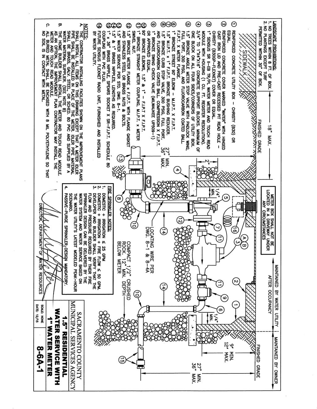
23 assembly shall be provided on the service line unless the sprinkler piping inside the residence is designed to connect to a remotely located water closet with a minimum one-half-inch outlet to ensure routine purging of water in the system. Other types of residences and buildings shall be provided with a separate fire service that has a separate connection to the water main. 4. The size of a standard single-family residential service line shall be 1.5 inches in diameter, with a 1-inch water meter. The size of a single-family residential service line for lots 30,000 square feet and larger, and for homes with a combined fire/domestic flow exceeding 50 gpm, shall be 1.5 inches in diameter, with a 1.5-inch water meter. 5. For all other services, the design domestic demand and the design maximum-day irrigation demand shall be calculated and submitted to Water Supply. Separate service lines and meters shall be provided for domestic and irrigation services if either (a.) the sum of the two numbers exceeds 50 gallons per minute, or (b.) the size of the irrigated landscape exceeds 5,000 square feet. 6. The normal minimum size of a commercial service line shall be 1.5 inches in diameter. Commercial, industrial, multi-family units, schools, parks, and landscape projects with higher water demands shall be provided with larger services, subject to approval by Water Supply. 7. Parks and landscape projects with non-irrigation water uses (bathrooms, fountains, water play, etc.) shall be provided with separate service lines and meters for domestic and irrigation services. Except that a single service may be used if the only nonirrigation demand is for drinking fountains. 8. Service lines shall be designed without bends when possible. For 2-inch and smaller services, if a bend is necessary, the bend shall be shown on the plan as a curve to indicate bending of the polyethylene pipe or copper tubing. D. Water Meters -- Water meters shall be installed on all residential, commercial, industrial, multi-family, school, park, and irrigation water services. Except as noted in Section 8-16.C.4, the size of water meter shall be the same size as the service line between the main and meter unless approved by Water Supply. The maximum allowable design flow shall be in accordance with the following: 8-21
24 METER SIZE (inches) METER TYPE MAXIMUM ALLOWABLE DESIGN FLOW* (gpm) 1 Positive Displacement Floating Ball Technology Compound 50 2 Floating Ball Technology Compound 80 3 Floating Ball Technology Compound Floating Ball Technology Compound Floating Ball Technology Compound 880 * Not including fire sprinkler flow. See the Standard Drawing 8-6 series for the required meter model and typical installation details. The maximum allowable combined design flow for meters conveying water for both consumptive use and fire sprinklers shall be the meter manufacturer s published maximum flow rate for the meter model and the maximum flow rate recommended by AWWA for the meter type, whichever is less. Meter box assemblies for single-family residential services shall be installed by the contractor installing facilities shown on the improvement plan at the time the water service lines are installed, except for the water meter itself which shall be deferred to the home builder for installation after building permits are issued. As an option, the water meter may be installed by the improvement plan contractor. All other meter box assemblies shall be installed by the improvement plan contractor at the time the water service lines are installed, including the water meter, unless approved by Water Supply. See the Standard Drawing 8-6 series for specifications and typical installation details. E. Fire Service Double Check Detector Valves -- A double check detector valve with bypass meter shall be required on each fire service line into a building. The size of the valve shall not be less than the size of the fire 8-22
25 service main. See Standard Drawing 8-7 for specifications and typical installation details. F. Back Flow Devices -- Back-flow devices are required in accordance with Title 17, Chapter V, and Sections of the California Administrative Code. 1. Double Check Detector Valves -- A double detector-check valve shall be required at each connection of a private water main to the public distribution system. The size of the valve shall not be less than the size of the main. See Standard Drawing 8-8C for specifications and typical installation details. 2. Reduced Pressure Principle Back Flow Devices -- A reduced pressure principle back flow device shall be required on the following services: commercial, industrial, school, park, irrigation, multi-family residential buildings, and services to any parcel or premises served water from a private well. Reduced pressure principle devices are for use on service lines only. See Standard Drawings 8-8A, 8-8B, and 8-8C for specifications and typical installation details. G. Air Release/Vacuum Valve Assemblies -- Air release/vacuum valve assemblies shall be required at high points in a distribution system as determined by Water Supply. Distribution mains shall require a 1-inch air release vacuum valve. See Standard Drawing 8-14A for specifications and typical installation details. In streets with roadside ditches, provide profiles of ARV lines and boxes. ARV boxes shall be located beyond the ditch. ARV lines shall not daylight in the ditch crossing. H. Blow-off Valves -- Blow-offs valves shall be required as specified in this section. 1. Temporary Blow-off Valve -- A 2-inch temporary blow-off valve shall be required at the end of water mains that will be extended in the future. See Standard Drawing 8-12 for specifications and typical installation details. 2. End of Main Blow-off Valve A 4-inch blow-off valve shall be required at the permanent end of water mains. See Standard Drawing 8-13A for specifications and typical installation details. 3. Cul-De-Sac Blow-off Valve -- A 4-inch blow-off valve shall be required at the end of a water main in a cul-de-sac, except in the 8-23
26 case that the line ends in a fire hydrant. The blow-off gate valve shall be located 2 feet past the last water service connection. See Standard Drawing 8-13B for specifications and typical installation details. 4. In-Line Blow-off Valve -- A 4-inch in-line blow-off valve shall be required at low points in the water distribution main as approved by Water Supply. See Standard Drawing 8-13C for specifications and typical installation details. In streets with roadside ditches, provide profile views of blow-off lines and boxes. When possible, blow-off valves and boxes shall be located beyond the ditch. I. Locating Wire Stations -- Locating wire stations shall be placed on distribution mains when the distance between valves and/or permanent and in-line blow-offs exceeds 600 feet. See Standard Drawing 8-4B for specifications and typical installation details. J. Water Sample Stations Water sample stations shall be provided at the rate of not less than one for every 500 new and existing units and at locations required by Water Supply. Water sample stations shall normally be located within a streetscape in a PUE. Alternate locations may be approved by Water Supply. Water Supply will provide typical installation details upon request. A water sample station shall consist of a 1-inch water service terminated inside a G-5 valve box with a 1-inch curb stop RECYCLED WATER TRANSMISSION AND DISTRIBUTION MAIN DESIGN: Recycled water facilities may be required by the Water Agency for use in specified areas as determined by Water Supply. Design flows and demands for recycled water systems shall be determined by the Water Agency. The design of recycled water transmission mains and distribution mains shall comply with the design requirements for potable water transmission mains and distribution mains with the following special provisions: 1. Recycled water mains shall be located on the south and east side of a street. A deviation from these criteria may be allowed if approved by Water Supply in consultation with other affected utility providers. 2. Recycled Water Main Separation -- Separation between recycled water mains and potable water mains and raw water mains shall comply with Section Water Main Separation of the California Code of Regulations. Separation may vary if approved by both the State Water Resources Control Board and by Water Supply. 8-24
27 3. To avoid cross connection of the potable and recycled water systems, recycled water facilities shall be clearly marked through appropriate coloring of pipe materials and above ground appurtenances. 4. All above ground facilities shall be marked with a sign to caution against drinking water from the recycled water system. All signs shall be made and placed in such a manner as to become a permanent part of the facility or appurtenance. Park sites, large turf areas, and other publicly used areas may require warning signs of the appropriate size as determined by Water Supply or other regulatory agency. See Standard Drawing 8-16 for specifications and installation details. 5. Recycled water services shall not be equipped with a back flow device. 6. Recycled water main plans shall include the standard SCWA Recycled Water Notes as provided by Water Supply RAW WATER TRANSMISSION MAIN DESIGN: Raw water transmission main facilities may be required by the Water Agency for use in specified areas as determined by Water Supply. Design flows and demands for raw water systems shall be determined by the Water Agency. The design of raw water transmission mains shall comply with the design requirements for potable water transmission mains with the following special provisions: 1. Raw water transmission mains shall be located on the north and west side of a street. 2. Raw Water Transmission Main Separation -- Separation shall comply with the requirements for supply lines in Section Water Main Separation of the California Code of Regulations. Separation may vary if approved by both the State Water Resources Control Board and by Water Supply. 3. Raw water plans shall include the standard SCWA Raw Water Notes as provided by Water Supply RECORD PLANS: Record Drawings shall be in accordance with Section 2-11 Record Plans of these Improvement Standards and shall also include the following water facility information: 1. The notation Record Drawing conspicuously stamped on each sheet. 2. The record information for changes to locations and stationing, and for changes to plan and profile of mains, pipes, valves, fittings, air release/vacuum valves, blow-off assemblies, hydrants, and water services. 8-25
28 3. Field-surveyed as-built top-of-pipe elevations at all ends of water mains equipped with a temporary blow-off valve or blind flange. 4. The pipe type and class of the water pipe installed at every location, clearly notated on each sheet, with the station of transitions between pipe types marked and notated. 5. The type of end fitting installed at the ends of all water mains equipped with a temporary blow-off valve. Record Drawings shall be approved by Water Supply prior to final acceptance of the project. 8-26
29
30
31
32
33
34
35
36
37
CHAPTER 5 WATER SYSTEM DESIGN STANDARDS
 CHAPTER 5 WATER SYSTEM DESIGN STANDARDS TABLE OF CONTENTS CHAPTER 5 WATER SYSTEM DESIGN STANDARDS 5.00 Objective Page 1 5.01 Additional Referenced Standards Page 1 5.02 Special Design Problems Page 2 5.03
TABLE OF CONTENTS PART III MINIMUM DESIGN STANDARDS Section 115 WATER DISTRIBUTION SYSTEM GENERAL SIZING LINES 115.
 TABLE OF CONTENTS PART III MINIMUM DESIGN STANDARDS Section 115 WATER DISTRIBUTION SYSTEM SECTION TITLE PAGE 115.1 GENERAL 115.1 115.2 SIZING LINES 115.1 115.3 DISTRIBUTION SYSTEM 115.2 115.3.1 Layout
UNIFORM DESIGN AND CONSTRUCTION STANDARDS FOR EXTENDING WATER DISTRIBUTION SYSTEMS SECTION 2 DESIGN STANDARDS
 UNIFORM DESIGN AND CONSTRUCTION STANDARDS FOR EXTENDING WATER DISTRIBUTION SYSTEMS SECTION 2 DESIGN STANDARDS DESIGN STANDARDS SECTION 2 INDEX ITEM DESCRIPTION 2.00 GENERAL STATEMENT 2.01 WATER DISTRIBUTION
SECTION 4 - DESIGN STANDARDS FOR WATER DISTRIBUTION FACILITIES
 SECTION 4 - DESIGN STANDARDS FOR WATER DISTRIBUTION FACILITIES 4.1 GENERAL REQUIREMENTS 4.1.1 Water and fire protection distribution facilities are to be provided solely for the purpose of supplying potable
CHAPTER 8 WATER SUPPLY SYSTEM
 CHAPTER 8 WATER SUPPLY SYSTEM 8-1 INTRODUCTION These improvement standards shall govern the engineering design of all domestic water systems intended for operation and maintenance by the County of Sutter
This is only a general checklist; please refer to the CVWD Development Design Manual (DDM) for all requirements and regulations.
 for all requirements and regulations.") COACHELLA VALLEY WATER DISTRICT DOMESTIC WATER CHECKLIST Tract/Parcel No: Project Common Name: Developer: Engineer: Engineer Signature: Date: Phone: Phone: Print: This is only a general checklist; please
COACHELLA VALLEY WATER DISTRICT DOMESTIC WATER CHECKLIST Tract/Parcel No: Project Common Name: Developer: Engineer: Engineer Signature: Date: Phone: Phone: Print: This is only a general checklist; please
SECTION 13 WATER SYSTEMS
 TABLE OF CONTENTS SECTION 13 WATER SYSTEMS 13.1 PURPOSE AND DEFINITIONS... 1 13.1.1 Purpose... 1 13.1.2 DOU Water System... 1 13.1.3 Definitions... 1 13.2 GENERAL REQUIREMENTS... 6 13.2.1 Authority and
CITY OF LA MARQUE, TEXAS CHAPTER 3 WATER SYSTEM DESIGN CRITERIA
 CITY OF LA MARQUE, TEXAS CHAPTER 3 WATER SYSTEM DESIGN CRITERIA CHAPTER 3 WATER SYSTEM DESIGN 3.1 WATER SYSTEM DESIGN GENERAL 3.1.1 Criteria for the design of water service and water distribution lines
SECTION 4 - DESIGN STANDARDS FOR WATER DISTRIBUTION FACILITIES
 SECTION 4 - DESIGN STANDARDS FOR WATER DISTRIBUTION FACILITIES 4.1. General Requirements 4.1.01 Water distribution and fire protection facilities are to be provided solely for the purpose of supplying
T a b l e o f C o n t e n t s
 C i t y o f G l a d s t o n e P u b l i c W o r k s D e s i g n S t a n d a r d s T a b l e o f C o n t e n t s SECTION THREE SANITARY SEWER REQUIREMENTS... 1 3.0000 SANITARY SEWERS... 1 3.0010 General
SECTION WATER MAINS CITY OF LEE S SUMMIT, MISSOURI DESIGN CRITERIA
 SECTION 6900 - WATER MAINS CITY OF LEE S SUMMIT, MISSOURI DESIGN CRITERIA 6901 DESIGN CRITERIA A. General 1. The design standards presented in the City of Lee's Summit Design Criteria are the minimum standards
4A General Information A. Concept... 1 B. Conditions... 1
 Design Manual Chapter 4 - Water Mains Table of Contents TOC Table of Contents Chapter 4 - Water Mains 4A General Information 4A-1---------------------------------General Information A. Concept....... 1
UTILITIES CHECKLIST CITY OF CHESAPEAKE DEPARTMENT OF PUBLIC WORKS SUBDIVISION NAME: A/C & TAX MAP PARCEL NOS (13 DIGITS) DEVELOPER:
 DEVELOPER:") UTILITIES CHECKLIST CITY OF CHESAPEAKE DEPARTMENT OF PUBLIC WORKS SUBDIVISION NAME: A/C & TAX MAP PARCEL NOS (13 DIGITS) DEVELOPER: REVIEWING ENGINEER: WATERSHED (INCLUDE SUBSCRIPT) I. PRELIMINARY ITEMS
UTILITIES CHECKLIST CITY OF CHESAPEAKE DEPARTMENT OF PUBLIC WORKS SUBDIVISION NAME: A/C & TAX MAP PARCEL NOS (13 DIGITS) DEVELOPER: REVIEWING ENGINEER: WATERSHED (INCLUDE SUBSCRIPT) I. PRELIMINARY ITEMS
PART VII - WATER SYSTEM DESIGN CRITERIA
 PART VII - WATER SYSTEM DESIGN CRITERIA A. Water Distribution, General 1. The water system layout shall be approved by the City Engineer. The fire hydrant layout shall be approved by the Redwood City Fire
APPENDIX B STANDARD CONSTRUCTION DRAWING NOTES
 APPENDIX B STANDARD CONSTRUCTION DRAWING NOTES B-1 General Notes: SACWSD Standard Construction Drawing Notes 1. No work shall begin on any water or wastewater construction project until the construction
WASHOE COUNTY DEPARTMENT OF WATER RESOURCES WATER DESIGN STANDARDS
 WATER DESIGN STANDARDS This section of the manual contains the Washoe County Department of Water Resources (DWR) standards for: Designing Water Distribution Facilities ( Design Standards ) 1.1 DESIGN STANDARDS
CITY OF MERIDIAN LAND DEVELOPMENT SERVICES SUBDIVISION PLAN REVIEW CHECK LIST
 Project Name: Hearing Date: Reviewer: Date of Review: # OK NEED N/A General Plan Design All documents, design standards, specifications, and forms should be taken from the website each time they are used
Permit for Construction of an Extension to a JEA Drinking Water Distribution System and/or JEA Wastewater Collection/Transmission System
 Permit for Construction of an Extension to a JEA Drinking Water Distribution System and/or JEA Wastewater Collection/Transmission System INSTRUCTIONS: This form shall be completed and submitted (in duplicate)
Ivins City Standard Specifications for Design and Construction Part 2 Engineering and Design Standards
 2.9. WATER SYSTEM DESIGN Ivins City Standard Specifications for Design and Construction All culinary water mains and appurtenances shall be designed to provide for adequate future service for all contiguous
SECTION I. (Sub-Section 3) Water Systems Design Standards. 3.1 General Plans Preparation 3-1
 Water Systems Design Standards. 3.1 General Plans Preparation 3-1") SECTION I (Sub-Section 3) Water Systems Design Standards Article Page 3.1 General 3-1 3.2 Plans Preparation 3-1 3.3 Design and Construction Standards 3-1 thru 3-2 3.4 Protection of Water Supply 3-4 3.5
SECTION I (Sub-Section 3) Water Systems Design Standards Article Page 3.1 General 3-1 3.2 Plans Preparation 3-1 3.3 Design and Construction Standards 3-1 thru 3-2 3.4 Protection of Water Supply 3-4 3.5
Chapter 3: Permit Procedures and Requirements
 Chapter 1: General Provisions 1 1 Short Title 1 2 Jurisdiction 1 3 Amendments and Revisions 1 4 Enforcement Responsibility 1 5 Review Process 1 6 Prior Approval 1 7 Relationship to Other Standards 1 8
CITY OF SASKATOON DESIGN AND DEVELOPMENT STANDARDS MANUAL SECTION FOUR WATER DISTRIBUTION SYSTEM
 CITY OF SASKATOON DESIGN AND DEVELOPMENT STANDARDS MANUAL SECTION FOUR WATER DISTRIBUTION SYSTEM 2018 TABLE OF CONTENTS Section Four Water Distribution System SECTION PAGE NUMBER 1. Objective...1 2. Submissions
DESIGN CRITERIA AND STANDARD DRAWINGS FOR WATER AND SEWER FACILITIES
 SANTA MARGARITA WATER DISTRICT DESIGN CRITERIA AND STANDARD DRAWINGS FOR WATER AND SEWER FACILITIES SANTA MARGARITA WATER DISTRICT 26111 Antonio Parkway Rancho Santa Margarita, California 92688 (949) 459-6655
A. Introduction 7 1. Purpose 7 2. Authority 7 3. Contact 8 4. Plan Submittal Process 8 B. Design Standards General 11 a. Future Extensions 11
 A. Introduction 7 1. Purpose 7 2. Authority 7 3. Contact 8 4. Plan Submittal Process 8 B. Design Standards 11 1. General 11 a. Future Extensions 11 b. Design Calculations 11 c. Easements and Property 12
CURRENT NORTH LAS VEGAS ADDENDA
 SECTION 1 Section 1.01.73 Fire Service Meter ADD: Type I is not approved for installation in the City of North Las Vegas service area. Section 1.01.107 Pressure Reducing Valve (PRV) or Pressure Regulator
SECTION 8 WATER SYSTEMS
 CONTENTS SECTION 8 WATER SYSTEMS 8-1 Introduction...8-1 8-2 Intent Of Water System Improvement Standards...8-1 8-3 Definitions...8-1 8-4 Applicable Standards...8-1 8-5 Water System Master Plan...8-2 8-6
Guidelines for Design of Potable Water Distribution Facilities In New Developments
 Guidelines for Design of Potable Water Distribution Facilities In New Developments Prepared by: OUC Water Business Unit Water Resources and Engineering Division Latest Update: September 29, 2009 1. Development
F. Provide at least 2 feet of vertical separation between a water line and any utility or stormdrain crossing it.
 Section 3 F. Provide at least 2 feet of vertical separation between a water line and any utility or stormdrain crossing it. 3.8 Highway Crossings The design engineer shall, prior to the design of any highway
SECTION 8 SEPARATION OF LINES
 SECTION 8 SEPARATION OF LINES 8.01 INDEX 8.01 INDEX 8.02 PURPOSE 8.03 DEFINITIONS 8.04 SEWER SEPARATION 8.05 NON-POTABLE SEPARATION 8.06 REFERENCES 8.02 PURPOSE This section states the requirements and
CITY OF MELISSA MANUAL FOR THE DESIGN OF WATER AND SANITARY SEWER LINES
 CITY OF MELISSA MANUAL FOR THE DESIGN OF WATER AND SANITARY SEWER LINES SECTION A NOTES TO ENGINEERS This manual is intended to aid and assist private engineers in the layout and design of sanitary sewers
CITY OF PANAMA CITY BEACH Utilities Administration & Engineering Offices 116 South Arnold Road Panama City Beach, FL 32413
 Page: 1 of 5 CITY OF PANAMA CITY BEACH Utilities Administration & Engineering Offices 116 South Arnold Road Panama City Beach, FL 32413 COMMERCIAL/RESIDENTIAL UTILITY PLAN COMPLETENESS CHECK LIST Updated
CITY OF OCEANSIDE WATER UTILITIES DEPARTMENT WATER, SEWER, AND RECLAIMED WATER DESIGN & CONSTRUCTION MANUAL SECTION 3
 CITY OF OCEANSIDE WATER UTILITIES DEPARTMENT WATER, SEWER, AND RECLAIMED WATER DESIGN & CONSTRUCTION MANUAL SECTION 3 SEWER SYSTEMS - DESIGN GUIDELINES TABLE OF CONTENTS PARAGRAPH TITLE PAGE 3.1 GENERAL...
WATER MAIN EXTENSION DESIGN REQUIREMENTS
 This guideline provides minimum requirements for the design of new water main extensions. This guide is not to be used as a substitution for the detailed design of the water system. The Developer s Engineer
**RESPONSES TO COMMENTS MUST BE RETURNED WITH REVISED PLANS FOR FINAL PLAN APPROVAL.** Approved as submitted X Needs attention N/A Non-Applicable
 PLAN REVIEW CHECKLIST FOR WATER MAINS AND SANITARY SEWERS CITY OF ANDERSON / ELECTRIC CITY UTILITIES ************************************************************************************* Project Name:
WASHOE COUNTY COMMUNITY SERVICES DEPARTMENT GRAVITY SEWER COLLECTION DESIGN STANDARDS
 GRAVITY SEWER COLLECTION DESIGN This section of the manual contains the Washoe County Community Services Department (CSD) standards for: INDEX Designing Gravity Sewer Collection Facilities ( Sewer Design
ENGINEERING REVIEW CHECKLIST City of Mount Clemens
 (To be completed by the Developer s & Submitted with ing Plans) DATE: PROJECT NAME: Site Plan Approved: Date DESIGN ENGINEERING COMPANY: ing Company Contact Information: Name: Phone: Email: Owner Contact
8 WATER DISTRIBUTION FACILITIES
 8 WATER DISTRIBUTION FACILITIES 8.01 Design Basis This Chapter provides minimum standards for the design and construction of water mains and appurtenances. All water main extensions of the City of Belmont
CHAPTER 12 INSTALLATION OF UTILITIES AND OTHER SYSTEMS TABLE OF CONTENTS
 CHAPTER 12 INSTALLATION OF UTILITIES AND OTHER SYSTEMS TABLE OF CONTENTS Section Title Page 12.1 General... 12-1 12.2 Design Standards... 12-1 12.2.1 General Requirements...12-1 12.2.2 Minimum Depth...12-1
WASHOE COUNTY DEPARTMENT OF WATER RESOURCES GRAVITY SEWER COLLECTION DESIGN STANDARDS
 GRAVITY SEWER COLLECTION DESIGN This section of the manual contains the Washoe County Department of Water Resource s (DWR) standards for: Designing Gravity Sewer Collection Facilities ( Sewer Design Standards
GENERAL INFORMATION AND REQUIREMENTS
 GENERAL INFORMATION AND REQUIREMENTS 1.0 BOARD S STANDARD SPECIFICATIONS: Copies of these Standard Specifications for Water Mains, Sanitary Sewers and Sewage Pumping Stations may be purchased from the
City of Logan Sanitary Sewer Design Standards
 City of Logan Sanitary Sewer Design Standards 2011 http://www.loganutah.org/public_works/engineering/stdsspecsdesign.cfm Table of Contents PART 1. CITY OF LOGAN SANITARY SEWER SYSTEM DESIGN STANDARDS FOR
GENERAL NOTES ROADWAY CONSTRUCTION RD0001-1A ISSUED:2017 REVISED: --
 ROADWAY CONSTRUCTION NOTES 1. ALL RIGHT-OF-WAY OTHER THAN ROADWAY AREAS SHALL BE SODDED. ALL SLOPE STEEPER THAN 6:1 SHALL REQUIRE SODDING. THE CITY RESERVES THE RIGHT TO REQUIRE SODDING IN SPECIAL AREAS
Contact the Jurisdictional Engineer for materials allowed by each jurisdiction.
 Design Manual Chapter 3 - Sanitary Sewers 3C - Facility Design 3C-1 Facility Design A. Capacity of Pipe Pipe sizes 15 inches and smaller should carry the peak flow at a depth of no more than 0.67 of the
CONSTRUCTION PLAN CHECKLIST
 CONSTRUCTION PLAN CHECKLIST The design engineer is responsible for ensuring that plans submitted for city review are in accordance with this checklist. It is requested that the executed checklist be submitted
SECTION VII WATER. Concrete anchor and thrust blocks shall be provided at all discontinuities in accordance with Standard Details G-7.1 and G-7.2.
 SECTION VII WATER VII-1. DESIGN GUIDELINES Water pipelines and appurtenant structures within the jurisdiction of the City of Paso Robles shall be constructed in accordance with plans prepared by a Professional
SECTION MEASUREMENT AND PAYMENT
 SECTION 01026 PART 1 GENERAL 1.1 SECTION INCLUDES A. Explanation and Definitions B. Measurement C. Payment D. Schedule of Values E. Application for Payment 1.2 EXPLANATION AND DEFINITIONS A. The following
SECTION 2 - DESIGN STANDARDS FOR GRAVITY SANITARY SEWERS
 SECTION 2 - DESIGN STANDARDS FOR GRAVITY SANITARY SEWERS 2.1. General Requirements Sanitary sewers are to be provided solely for the removal of sanitary waste. Under no circumstances shall any roof drains,
Water Design and Construction
 SECTION 2 Water Design and Construction 2.1 Introduction: Design Responsibility and Applicability of Requirements The design and construction requirements for water distribution mains and related appurtenances
1. Required Minimum Flow:
 SECTION 6 6. 6.01 General The City of Castle Rock Water System Minimum Standards and Specifications are minimum base level performance, design, and construction standards used to maintain uniformity of
All service lines shall conform to the following requirements:
 505 WATER SERVICE INSTALLATION 505.1 DEFINITION A service line is comprised of the piping and related appurtenances including the connection installed from the Des Moines Water Works water main to the
SECTION 2 Design Manual
 SECTION 2 Design Manual This page intentionally left blank SECTION 2 STANDARD REQUIREMENTS FOR DESIGN OF DOMESTIC WATER AND SANITARY SEWER FACILITIES 2.01 GENERAL WATER AND SEWER REQUIREMENTS All proposed
WATER AND SANITARY SEWER
 RUBIDOUX COMMUNITY SERVICES DISTRICT WATER AND SANITARY SEWER DESIGN & CONSTRUCTION MANUAL THIS PAGE INTENTIONALLY BLANK RUBIDOUX COMMUNITY SERVICES DISTRICT WATER AND SANITARY SEWER SYSTEM DESIGN AND
TOWN OF MIDDLETOWN, MD W-1 (05/99)
") WATER SYSTEM DESIGN MANUAL 1.0 GENERAL 1.1 Introduction This chapter of the Middletown Design Manual outlines the policies, minimum design criteria and design procedures for the preparation of feasibility
WATER SYSTEM DESIGN MANUAL 1.0 GENERAL 1.1 Introduction This chapter of the Middletown Design Manual outlines the policies, minimum design criteria and design procedures for the preparation of feasibility
PUBLIC WORKS DEPARTMENT GENERAL NOTES
 PUBLIC WORKS DEPARTMENT GENERAL NOTES 1. All construction shall be in strict accordance with the standards of the City of Southlake and governed by the North Central Texas Council of Government's Standard
WATER DISTRIBUTION STANDARD SPECIFICATIONS
 WATER DISTRIBUTION STANDARD SPECIFICATIONS Adopted by the Santa Rosa City Council Resolution No. RES-2017-177 00000 September 5, 2017 TABLE OF CONTENTS 1. Water Distribution System Design Standards 2.
401 Sanitary Sewer System Design Criteria. The following additional design requirements shall also apply:
 SECTION 400 SANITARY SEWER SYSTEM The design of sanitary sewers shall be in conformance with the applicable sections of the State of Washington, Department of Ecology manual, Criteria for Sewage Works
PART II. - SPECIFICATIONS AND DESIGN STANDARDS TO CITY OF HEWITT, TEXAS SUBDIVISION ORDINANCE FOR PUBLIC WORKS CONSTRUCTION [TEXT]
![PART II. - SPECIFICATIONS AND DESIGN STANDARDS TO CITY OF HEWITT, TEXAS SUBDIVISION ORDINANCE FOR PUBLIC WORKS CONSTRUCTION [TEXT]](/thumbs/80/81891816.jpg "PART II. - SPECIFICATIONS AND DESIGN STANDARDS TO CITY OF HEWITT, TEXAS SUBDIVISION ORDINANCE FOR PUBLIC WORKS CONSTRUCTION [TEXT]") PART II. - SPECIFICATIONS AND DESIGN STANDARDS TO CITY OF HEWITT, TEXAS SUBDIVISION ORDINANCE FOR PUBLIC WORKS CONSTRUCTION [TEXT] A. - General. B. - Streets. C. - Stormwater drainage system. D. - Water
PART II. - SPECIFICATIONS AND DESIGN STANDARDS TO CITY OF HEWITT, TEXAS SUBDIVISION ORDINANCE FOR PUBLIC WORKS CONSTRUCTION [TEXT] A. - General. B. - Streets. C. - Stormwater drainage system. D. - Water
3.0 DESIGN CRITERIA FOR SANITARY SEWER FACILITIES
 3.0 DESIGN CRITERIA FOR SANITARY SEWER FACILITIES All sanitary sewers shall be designed in accordance with these Design Standards, LBWD Rules and Regulations, and to accepted engineering principles. In
City of Middletown WATER & SEWER DEPARTMENT 82 Berlin Street Middletown, CT TEL: (860) FAX: (860)
 FAX: (860)") City of Middletown WATER & SEWER DEPARTMENT 82 Berlin Street Middletown, CT 06457 TEL: (860) 638-3500 FAX: (860) 343-8091 GENERAL REQUIREMENTS WATER MAIN AND SERVICE INSTALLATION JANUARY 2017 WATER MAINS:
City of Middletown WATER & SEWER DEPARTMENT 82 Berlin Street Middletown, CT 06457 TEL: (860) 638-3500 FAX: (860) 343-8091 GENERAL REQUIREMENTS WATER MAIN AND SERVICE INSTALLATION JANUARY 2017 WATER MAINS:
Section V WATER DISTRIBUTION SYSTEM DESIGN GUIDELINES
 Section V WATER DISTRIBUTION SYSTEM DESIGN GUIDELINES A. GENERAL 1. The following water system design guidelines are based on Federal, State and local health requirements and the Hilton Head No. 1 Public
Section 7 Design Criteria Irrigation and Drainage Facilities
 Section 7 Design Criteria Irrigation and Drainage Facilities 7.1 Background The Irrigation and Drainage system is comprised of the Coachella Branch of the All-American Canal (Coachella Canal), Protective
DESIGN STANDARDS SECTION DS 7 STREET LIGHTING
 DESIGN STANDARDS SECTION DS 7 STREET LIGHTING DS 7-01 GENERAL: A. INTENT: The intent of these Design Standards is to provide minimum standards for the design of street lighting to serve the ultimate level
120 WATER DISTRIBUTION SYSTEMS
 120 WATER DISTRIBUTION SYSTEMS 120.01 GENERAL 120.01.01 All public water main extensions shall by designed by a Design Professional and shall be approved by the Public Water Supply Section of NCDEQ/DEH.
TOWN OF MANCHESTER PLANNING AND ZONING COMMISSION Subdivision Application Minimum Submission Requirements
 TOWN OF MANCHESTER PLANNING AND ZONING COMMISSION Subdivision Application Minimum Submission Requirements This checklist is to be completed and submitted with all Subdivision Applications. The Town reserves
SECTION 13 - EXISTING FACILITIES TABLE OF CONTENTS
 SECTION 13 - EXISTING FACILITIES TABLE OF CONTENTS Section Page 13-1 GENERAL... 13.1 13-1.01 Preservation of Property... 13.1 13-1.02 Overloading, Pavement Protection & Repair... 13.1 13-2 REMOVING EXISTING
CHAPTER 17: STORM SEWER STANDARDS Introduction Administration Standards 17.1
 CHAPTER 17: STORM SEWER STANDARDS 17.00 Introduction 17.01 Administration 17.02 Standards 17.1 17.00 INTRODUCTION The purpose of this chapter is to provide guidance for the design and construction of storm
SECTION IV DESIGN CRITERIA FOR RECYCLED WATER DISTRIBUTION SYSTEMS
 SECTION IV DESIGN CRITERIA FOR RECYCLED WATER DISTRIBUTION SYSTEMS SECTION IV DESIGN CRITERIA FOR RECYCLED WATER DISTRIBUTION SYSTEMS Recycled water system improvements proposed for inclusion into the
WATER DISTRIBUTION DESIGN GUIDELINES
 CHAPTER THREE WATER DISTRIBUTION DESIGN GUIDELINES I. GENERAL A. LOCAL PERMITTING AUTHORITY In December 2003, PWC initiated its delegated Local Permitting program. In accordance with applicable North Carolina
SECTION WASTEWATER FORCE MAINS
 SECTION 02732 WASTEWATER FORCE MAINS PART - GENERAL 1.01 GENERAL: A. This section includes the general requirements for design and installation of force main systems serving wastewater lift stations. B.
Underground Piping for Private Hydrants & Sprinkler Supply Line
 City of Brea Brea Fire Department Fire Prevention 1 Civic Center Circle Phone: (714) 990-7655 Underground Piping for Private Hydrants & Sprinkler Supply Line PURPOSE The provision of adequate water supplies
STANDARD SPECIFICATIONS
 TOWN OF COLONIE DEPARTMENT OF PUBLIC WORKS DIVISION OF PURE WATERS STANDARD SPECIFICATIONS for RESIDENTIAL SANITARY SEWER CONNECTIONS Latest Revision Date: November 2017 TABLE OF CONTENTS Section Page
PUBLIC WORKS DESIGN, SPECIFICATIONS & PROCEDURES MANUAL LINEAR INFRASTRUCTURE
 REGION OF PEEL PUBLIC WORKS DESIGN, SPECIFICATIONS & PROCEDURES MANUAL LINEAR INFRASTRUCTURE Watermain Design Criteria REVISED June 2010 PUBLIC WORKS WATERMAIN DESIGN CRITERIA TABLE OF CONTENTS 1. INTRODUCTION...
SECTION WATER DISTRIBUTION SYSTEM
 Conditions of Use/ Responsibility of Data Montgomery County Public Schools Facilities Guide DIVISION 2 - SITE WORK These guideline specifications are to be used by the A/E as a base document in the development
CONSTRUCTION SURVEY. Construction survey includes personnel, equipment, and supplies required for, but not limited to, the following:
 CONSTRUCTION SURVEY PART 1 - GENERAL 1.01 SECTION INCLUDES Construction survey includes personnel, equipment, and supplies required for, but not limited to, the following: A. Construction Survey: 1. Project
CLEVELAND DIVISION OF WATER CONSTRUCTION STANDARDS. Details Index
 CLEVELAND DIVISION OF WATER CONSTRUCTION STANDARDS Details Index PLAN REVIEW AND DESIGN REQUIREMENTS SERVICE CONNECTION REQUIREMENTS EASEMENTS FOR WATER SUPPLY MAINS, CIRCULATION MAINS, AND VAULTS HYDRANT
SUBDIVISION IMPROVEMENT PLANS FORM
 Page 1 of 9 CITY OF CONROE SUBDIVISION IMPROVEMENT PLANS CHECKLIST SUBMIT THREE FINAL SETS OF PLANS (maximum size 24 X36 ), OTHER ITEMS LISTED, AND THIS COMPLETED, CERTIFIED CHECKLIST TO THE ENGINEERING
SECTION PUBLIC WATER SERVICE CONNECTIONS
 SECTION 33 14 14 PUBLIC WATER SERVICE CONNECTIONS PART 1 GENERAL 1.1 SUMMARY A. Section Includes: 1. Pipe and fittings for water service connections to small commercial, light industrial, and residential
City of Redding Construction Standards Index
 City of Redding Construction Standards Index A. Purpose and Reference Documents... A1 B. Modifications to the Standard Specifications for Public Works Construction (Greenbook)... B1 I. Streets Materials...
SUBDIVISION CHECKLIST. Subdivision Name. Prior To Review. Preliminary plan approved by Planning Commission / Council as required.
 SUBDIVISION CHECKLIST Subdivision Name Account Number Review Engineer Prior To Review Preliminary plan approved by Planning Commission / Council as required. Review fee paid. Statement of Responsibility
If a new residence s electrical service is not located within 200 feet of existing
 Primary Line Extensions CHAPTER 4 If a new residence s electrical service is not located within 200 feet of existing primary electrical facilities, a primary line extension is required to place a close
CONSTRUCTION PLAN REVIEW CHECKLIST FOR PRIVATE DEVELOPMENT
 ADDITION NAME: City of Grapevine, Texas CONSTRUCTION PLAN REVIEW CHECKLIST FOR PRIVATE DEVELOPMENT Updated April 16, 2018 Public Works Department Engineering Division 200 South Main Street Grapevine, Texas
University of Central Florida Main Campus. Domestic Water. Service and Meter Installations Requirements. Issued January 26 th, 2017.
 University of Central Florida Main Campus Domestic Water Service and Meter Installations Requirements Issued January 26 th, 2017 1 P a g e Table of Contents 1. GENERAL INFORMATION... 3 2. DEFINITIONS...
3.9 times the average 3.8 times the average 3.6 times the average
 ARTICLE VI DESIGN OF SANITARY SEWERS M'RSMIN. VOL.281 JA 2 4 2001 IMAGE; Section 601 Determination of the Amount of Sewage for Sanitary Sewers A. MSD Design Standards for estimating sanitary sewage flow
CULINARY WATER SYSTEMS
 CULINARY WATER SYSTEMS I. Water system size determination A. The minimum water line size is 8 inch for distribution lines in a residential subdivision. 1. Subdivisions that have a school or church will
SEWER SYSTEM DESIGN GUIDELINES
 SEWER SYSTEM DESIGN GUIDELINES PART 1 GENERAL 1.1 GENERAL GUIDELINES A. The following sewer system design guidelines are based on Federal, State and Local health requirements, and the Berkeley County Water
OVERALL UTILITY PLANS 1. Provide a typical section depicting the roadway (proposed/future), utility locations, and separation for
, utility locations, and separation for") OVERALL UTILITY PLANS 1. Provide a typical section depicting the roadway (proposed/future), utility locations, and separation for all roadways. Identify utility locations/separations from gutter lip and
OVERALL UTILITY PLANS 1. Provide a typical section depicting the roadway (proposed/future), utility locations, and separation for all roadways. Identify utility locations/separations from gutter lip and
CUYAHOGA COUNTY DEPARTMENT OF PUBLIC WORKS CUYAHOGA COUNTY ENGINEER TOWNSHIP SUBDIVISION STREET DESIGN STANDARDS AND IMPROVEMENT PLAN REQUIREMENTS
 CUYAHOGA COUNTY DEPARTMENT OF PUBLIC WORKS CUYAHOGA COUNTY ENGINEER TOWNSHIP SUBDIVISION STREET DESIGN STANDARDS AND IMPROVEMENT PLAN REQUIREMENTS November 25, 2013 Table of Contents Cuyahoga County Engineer's
SECTION CONSTRUCTION SERVICES
 SECTION 01100 CONSTRUCTION SERVICES PART 1 GENERAL 1.01 - Section Includes A. Mobilization. B. Construction Surveys. C. Record Documents. 1.02 Description Of Work A. Mobilization: includes the preparatory
SECTION UNIT PRICES. A. This Section specifies administrative and procedural requirements for the unit prices.
 SECTION 01220 UNIT PRICES PART 1 GENERAL 1.01 SUMMARY A. This Section specifies administrative and procedural requirements for the unit prices. B. The omission of any unit price description from this Section
STREET IMPROVEMENTS (Refer to Title 18, chapter entitled "STREETS" of the Layton Municipal Code.)
") STREET IMPROVEMENTS (Refer to Title 18, chapter 18.24 entitled "STREETS" of the Layton Municipal Code.) I. Street widths STREET TYPE (ALL MEASUREMENTS IN FEET) ROW WIDTH LAYTON CITY STANDARD STREET SECTIONS
STREET IMPROVEMENTS (Refer to Title 18, chapter 18.24 entitled "STREETS" of the Layton Municipal Code.) I. Street widths STREET TYPE (ALL MEASUREMENTS IN FEET) ROW WIDTH LAYTON CITY STANDARD STREET SECTIONS
7. Allowable Fittings.
 7. Allowable Fittings. a. General Requirements. 1) The fittings listed in this section are generally the allowable fittings for the design of DIP and PVC pipe. For steel pipe and fittings, see Part One,
Public Water Supply District #2 of St. Charles County, Missouri
 Public Water Supply District #2 of St. Charles County, Missouri POLICIES, PROCEDURES, AND REQUIREMENTS FOR CONNECTION AND INSPECTIONS OF: RESIDENTIAL WATER AND/OR SEWER SERVICE CONNECTIONS COMMERCIAL WATER
SECTION WASTEWATER FORCE MAINS
 SECTION 02732 WASTEWATER FORCE MAINS PART 1 GENERAL 1.01 GENERAL: A. This section includes the general requirements for design and installation of force main systems serving wastewater lift stations. B.
HARKERS ISLAND SANITARY DISTRICT AMENDMENT TO WATER SYSTEM MANAGEMENT PLAN
 HARKERS ISLAND SANITARY DISTRICT AMENDMENT TO WATER SYSTEM MANAGEMENT PLAN WHEREAS, the Harkers Island Sanitary District is a body politic and corporate with jurisdiction over that geographic area known
TECHNICAL SPECIAL PROVISION FOR FINANCIAL PROJECT ID:
 TECHNICAL SPECIAL PROVISION FOR 1001 WATER DISTRIBUTION SYSTEM FINANCIAL PROJECT ID: 200105-7-52-01 The official record of this Technical Special Provision is the electronic file signed and sealed under
TOWN of LAKESHORE SUBDIVISION DEVELOPMENT PLAN CHECKLIST
 Project Name: Project Location: Date Submitted: TOWN of LAKESHORE SUBDIVISION DEVELOPMENT PLAN CHECKLIST Last Revised January 31, 2014 Name Phone Number E-mail Address Owner: Contractor/ Engineer: ( )
Index. Composition and Order of Plan Set. Utility Plan... 5
 City of Des Plaines Public Works and Engineering Department Revised-October 5, 2012 Index Composition and Order of Plan Set Title Page Number Cover Sheet... 1 Requirements for Site Development... 2 Grading
SECTION MAINTENANCE OF EXISTING CONDITIONS
 SECTION 02 01 00 MAINTENANCE OF EXISTING CONDITIONS PART 1 GENERAL 1.1 GENERAL A. The CONTRACTOR shall protect all existing utilities and improvements not designated for removal and shall restore damaged
UNIFORM DESIGN AND CONSTRUCTION STANDARDS FOR EXTENDING WATER DISTRIBUTION SYSTEMS SECTION 2 DESIGN STANDARDS
 UNIFORM DESIGN AND CONSTRUCTION STANDARDS FOR EXTENDING WATER DISTRIBUTION SYSTEMS SECTION 2 DESIGN STANDARDS Revised: September 20, 2017 DESIGN STANDARDS SECTION 2 INDEX Article Title 2.01 General Statement