Construction Procedures
|
|
|
- Margaret Gray
- 6 years ago
- Views:
Transcription

1 Construction Procedures 2014 Rev


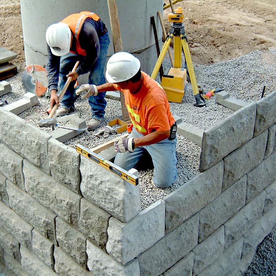
2 Introduction This manual presents the methods and procedures necessary for the proper erection of a LOCK+LOAD retaining wall. problems later during the service life of the masonry wall structure. The LOCK+LOAD wall system provides uniform compaction from the face to the far end of the soil reinforcement creating a monolithic mass of reinforced soil faced with 5500 psi steel reinforced concrete. Second, each LOCK+LOAD module is independently stable and does not stack upon the lower wall modules. This allows the wall structure to consolidate as it is being erected and therefore eliminates unwanted stress in the wall face and soil reinforcement. Third, LOCK+LOAD places the soil reinforcement (geo-grid etc.) at the mid-point of the panel where the grid is contact only with the backfill (just as it is everywhere else in the fill) and so cannot be damaged by being sandwiched between rigid masonry blocks. Each LOCK+LOAD module consists of two pieces, a panel and counterfort that are easily assembled at the project site; as shown in the picture above. LOCK+LOAD also has several unique aspects that require procedures different and at times in direct contravention of procedures commonly used in the building of other masonry block retaining walls. First and most importantly, LOCK+LOAD allows and requires full compaction all the way to the face of the wall (back of the panel). This is required because the reinforced concrete fascia is held in place by friction between the backfill and the counterfort. Typical masonry wall procedures require only light compaction within three feet of the wall face to avoid misalignment due to compaction forces. This zone of light compaction may cause The Vertical locking force on the LOCK+LOAD counterfort is always larger than the horizontal loads placed upon the wall panel allowing large compaction equipment to be used in close proximity to the wall face. 2


3 Layout Base Row Consult Engineer: Locate survey control points and confirm with the engineer that foundation soils have adequate bearing capacity for the wall height and then if necessary strengthen the foundation where required. Once foundation condition, wall plan and schedule is approved construction may begin. Excavate for the foundation pad: Remove surface vegetation and organic soils and then excavate a minimum 36 wide foundation to 6 below base elevation. If there are elevation steps in the foundation cut each step 16 higher than the next lower level. Access to a laser level this will greatly accelerate this process allowing grade to be checked all along the wall alignment. Other leveling devices may be used, but must be accurate. Foundation cut is a minimum of 36 wide to allow for a drainage pipe at the foundation level behind the counterforts or geo-grid. Drain system placement, is site, and soil specific and must be constructed in accordance with the plan. Set Bottom Row: Except for special circumstances always begin the building a wall from the lowest point of the alignment. Set one panel at each end of the wall section to be constructed. Check panel with survey markers for correct position from survey hub. Place carpenters level on back of panel and plumb by adding or subtracting grading material under counterfort until panel is vertical. Place level on top of panel and level horizontally in the same manner. Check top elevation of both panels on each end of wall segment being constructed with laser level to ensure run will be level. Compact foundation pad: Place ¾ Minus stone 6 deep or as required and compact to 95% Modified Proctor (typically a minimum of 4 passes with a 750 lb or larger reversible vibrating plate compactor). When the base pad is compacted layout panels face down along the wall alignment and attach counterforts. 3

4 Base Row cont. Secure a metal stake at each, set and leveled, panel ( 50 to 80 ft apart ) and run a string line the entire distance of wall segment to be constructed. Additional stakes at may be added to eliminate sag in the string line. Double check alignment, with laser or survey instrument. Now set the intervening panels along the string line. At this point, the top rear of panels will vary slightly off the string line. Adjust panel alignment by adding or subtracting gravel from underneath each counterfort until all panels align with string. If adding material under counterfort, make sure to tamp material tight. Height adjustment, if necessary, is conducted in the same manner adding or subtracting grading material. Slight variations of panels exceeding string line height, can be adjusted by tapping the top of the panel with a sledge hammer using a piece of scrap lumber to prevent chipping of the concrete (similar to setting bricks in mortar). Low panels can be adjusted up by tipping them forward and adding gravel under base of panel Use wedges between the counterfort head and the panel back to remove play and make the module rigid. to raise its elevation. Invest the necessary few minutes to perfect the alignment of the bottom row as it will save time later and helps assure a beautiful, strait, level, aligned wall. After some practice this process becomes quick, efficient, and productive. Accurate alignment and quality compaction are the difference between a good and excellent wall installation. 4
 non-engineered walls the drainpipe will be located at the rear of the counterfort and on the leveling pad (lowest elevation).")


5 Drainage & Backfill Place drainpipe: and drainage stone (aggregate) as specified on the plans, or as approved by engineer. On short (4 ft & less) non-engineered walls the drainpipe will be located at the rear of the counterfort and on the leveling pad (lowest elevation). On walls using geo-grid it may be at the backend of the geo-grid. Check the plans! For rows that will contain soil reinforcement the grid is placed after the first lift of fill is compacted so that geo grid is located at about the mid-point of the wall panel. Backfill : Start by placing backfill material over the tail of the counterfort first. Keep a minimum of 2.0 ft. of select 3/4 clear crushed rock material behind wall face for the foundation of the next row. Beyond this use the specified backfill material. Placement is approximate and need not be perfect. Panel rows should be back filled and compacted in two lifts of ~8 with the second lift rising to approximately 2 above panels top edge so that the compacted soil will consolidate to top of panel. Make minor field adjustments as necessary. Once select fill material is placed over the counterforts the specified backfill can be placed, leveled and compacted in ~8 lifts within the reinforced soil zone using heavy equipment. Take care not to displace the wall alignment or damage soil reinforcement. 5

6 Compaction Compact in 8 lifts using a plate compactor of 750 lbs. minimum, since the ability to compact ~18 of soil is required to erect a row of panels two lifts will be required. If a smaller compactor is used lifts must be reduced to 8 maximum and each coarse of panels compacted in three lifts. Compaction to 95% Modified Proctor is required and should be checked and verified by the Geotech. For granular crushed rock typically a minimum of 4 passes of the plate compactor will be required. Compact along the horizontal distance of the wall, and then proceed to back of the rein forced fill zone. Finally finish with the plate compactor up to and abutting the wall face. Note: This differs from typical modular block wall systems that specify Light Equipment compaction within 3 to 5 behind the wall face. LOCK+LOAD retaining walls require compaction to the wall face, because the counterfort is Even better compaction equipment are large reversible diesel plate compactors with operating weights of 900 to 1100 lbs. [Examples: Wacker models (BPU-3345) or Multi Quip (MVH-200DA) or equivalent]. Roller compactors can safely be used to within 16 of the wall face. All compaction activity always begins with compacting over the tail of the counterfort first locking it into place. the facings attachment to the soil mass. Safety dictates keeping large ride on rollers a minimum of 16 behind the wall face and using the large plate compactors to compact this area. For taller walls local codes may require that this no ride zone increase. 6

7 Subsequent Rows Leveling for Next Row: Using a flat point shovel scrape along the first 5 of wall face using the top of the previous coarse as a guide until level. Note: PANELS DO NOT STACK!!! Back needs to be level with the top of previous panel and compacted. The 1 gap at the base of the next panel is for isolation, movement during a seismic event, and to allow for mass consolidation in taller walls. Repeat layout & align step 4, backfill step 6 and, compact step 7, etc. 7


8 Subsequent Rows cont. Geo-grid Placement: When installing geo-grid in the reinforced soil mass, backfill only approximately ½ the way up panel back making sure that the fill is evenly distributed and about level over the whole grid area. Compact, this lift of fill being careful over the counterforts. Roller compactors may not be used to compact on the first lift over the, barley covered, counterforts since they may be damaged. Once compacted and ~leveled place geogrids with grid directional strength, perpendicular to the wall face. Check against the plans to insure that the geo-grid is the proper strength and length for its position in the retaining wall structure. Place the geogrid so that a minimum of 3 inches remains vertical and in contact with the panel back. Now carefully backfill over the grid, to the top of wall panel, keeping the geo-grid tight and free of wrinkles., A minimum of 2 foot of select material is to be maintained at the wall face. Compact as previously described beginning over the tail of the counterfort to the panel back and then toward the back end of the geo-grid Insure that the geogrid remains in contact with the panel back after compaction. When the back fill is compacted to specification and leveled to the top of the panels the compaction should be checked and approved by the engineer, as required, before construction proceeds. Once approved this construction sequence repeats for the next and subsequent rows until the wall is completed. 8

9 The Steps In Pictures 9


10 Variations Radius Inside and Outside: Curve alignment can be accomplished in several ways an easy method for short radii is to use a rope from a single radius point and swinging an arc. Set the first panel and the next panel will abut it and the opposite edge distance is checked with the rope. Longer radius curves generally will be set as off sets from survey stakes. Once several units are set a string line is run along the outside of the panels and slight a variations removed. For tight curves of 8 radius or less: use half wide panels and construct in the same manner as standard curves. Outside corners are made using the LOCK+LOAD corner panels. When possible begin walls at outside corners to minimize panel trimming if on bond erection is required. Note: Corner counterfort may need to be chipped to round the head so that it can be rotated to avoid interference with adjacent panel counterforts. Corners: LOCK+LOAD does not need to be built on bond but if it is required, for aesthetic reasons, the panels will need to be trimmed for inside corners. The need to trim panels is due to the wall batter. On inside corners the length of subsequent rows grows by 40 mm or 1 9/16. Using a diamond blade cut off saw mark cuts on panel back according to the attached detail and trim to lengths required to maintain the split bond. 10


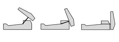
11 Step by Step Retaining Module Assembly Prepare Foundation & Layout 1st Row Compact Over Counterfort Tail First 11
Redi Rock Specification and Installation Manual
 Redi Rock Specification and Installation Manual 1.0 General Scope This Specification covers the Design, Materials and Installation of Redi Rock modular block Retaining and Freestanding Wall systems as
Steps And Stairs Installation Option 1 - Steps In Wall Option 2 - Steps With Plant Space Option 3 - Steps In Front of Walls Option 4 - Steps Along
 Steps And Stairs Installation Option 1 - Steps In Wall Option 2 - Steps With Plant Space Option 3 - Steps In Front of Walls Option 4 - Steps Along Wall Face Option 5 - Steps In Wall; 10 (25cm) Tread Option
Uwall UNIVERSAL CONSTRUCTION MANUAL
 Uwall UNIVERSAL Retaining Wall System CONSTRUCTION MANUAL TM President s Letter CSI is a leader in its industry supplying precast infrastructure products throughout New England and beyond since 1972, developing
Steps And Stairs Installation Steps In Wall - Option 1 Steps In Front of Walls - Option 2 Steps In Wall; 10 (25cm) Tread - Option 3 Step Parallel to
 Tread - Option 3 Step Parallel to") Steps And Stairs Installation Steps In Wall - Option 1 Steps In Front of Walls - Option 2 Steps In Wall; 10 (25cm) Tread - Option 3 Step Parallel to Wall - Option 4 Steps and Stairs Q & A E CONSTRUCTION
Steps And Stairs Installation Steps In Wall - Option 1 Steps In Front of Walls - Option 2 Steps In Wall; 10 (25cm) Tread - Option 3 Step Parallel to Wall - Option 4 Steps and Stairs Q & A E CONSTRUCTION
NOVEMBER 2016 MAGNUMSTONE. retaining walls installation manual
 NOVEMBER 2016 MAGNUMSTONE retaining walls installation manual AUSTRAL MASONRY CONTENTS Magnumstone Installation Guide 04 Overview 07 Unit Specifications 08 Installation 08 Gravity MagnumStone Wall 16 Geogrid
LANDSCAPE RETAINING WALLS
 SUDAS Standard Specifications Division 9 - Site Work and Landscaping Section 9070 - Landscape Retaining Walls LANDSCAPE RETAINING WALLS PART - GENERAL.0 SECTION INCLUDES A. Modular Block Retaining Walls
AUGUST 2017 HASTINGS. retaining walls installation guide
 AUGUST 2017 HASTINGS retaining walls installation guide RETAINING WALL INSTALLATION GUIDE RETAINING WALL information Austral Masonry retaining wall blocks are an ideal choice for retaining walls in gardens,
SPECIFICATIONS FOR PRECAST MODULAR BLOCK RETAINING WALL SYSTEM (revised 5/8/7)
") Page 1 of 7 STONE STRONG SYSTEMS SPECIFICATIONS FOR PRECAST MODULAR BLOCK RETAINING WALL SYSTEM (revised 5/8/7) PART 1: GENERAL 1.01 Description A. Work includes furnishing and installing precast modular
Page 1 of 7 STONE STRONG SYSTEMS SPECIFICATIONS FOR PRECAST MODULAR BLOCK RETAINING WALL SYSTEM (revised 5/8/7) PART 1: GENERAL 1.01 Description A. Work includes furnishing and installing precast modular
How To Install Your Cambridge Pavingstones System How To Install Your Cambridge Segmental Retaining Wall System
 4 How To Install Your Cambridge Pavingstones System Step 1. Preparation: Sketch a diagram of area to be paved. Square off a 90-degree corner. Set stakes for outside perimeters 6 inches away from area.
at home installation guide Manufactured by:
 at home outdoorsproduct and installation guide Manufactured by: Product and Installation Guide Wall Systems Table of Contents Wall Systems...3-7 Project Planning and Installation... 8-11 DIY Retaining
ICC-ES Evaluation Report Issued July 1, 2011 This report is subject to renewal in one year.
 ICC-ES Evaluation Report ESR-1959 Issued July 1, 2011 This report is subject to renewal in one year. www.icc-es.org (800) 423-6587 (562) 699-0543 A Subsidiary of the International Code Council DIVISION:
Retaining Wall Systems
 Retaining Wall Systems A family of Retaining Wall Products The versatile Allan Block product line allows easy design and construction of retaining walls to meet specific engineering and site requirements.
MODULAR CONCRETE RETAINING WALL
 MODULAR CONCRETE RETAINING WALL PART 1: GENERAL 1.01 Description A. Work shall consist of furnishing and construction of a KEYSTONE Retaining Wall System or equal in accordance with these specifications
STANDARD SPECIFICATION FOR CRIBLOCK CONCRETE CRIBWALL
 STANDARD SPECIFICATION FOR CRIBLOCK CONCRETE CRIBWALL 1. SCOPE 2. DESIGN 3. MATERIALS 4. CONSTRUCTION 5. METHOD OF MEASUREMENT AND PAYMENT SCOPE This Specification sets out requirements for the design,
MACHINE-LAY Installation Manual
 MACHINE-LAY Installation Manual PaveDrain Installation Manual Table of Contents Section 1: Base Preparation (pages 3 6) Section 2: Machine-Lay PaveDrain Blocks (pages 8 11) Section 3: Edge Restraints (pages
HOW TO BUILD Garden Walls Frestanding & Landscape Walls
 HOW TO BUILD Garden Walls Frestanding & Landscape Walls 10 Cambridge Wall Book Garden walls This layout depicts a common application of landscape and freestanding designs together in one wall with Columns
MUTUAL MATERIALS TECH SHEET RomanStack. Coverage* 4.5 pcs / ft² (48.44 pcs / m²) 3,242 lb (1,470 kg) 4 x 8 Cap Unit. 1.6 pcs / ln ft (4.
 3,242 lb (1,470 kg) 4 x 8 Cap Unit. 1.6 pcs / ln ft (4.") Available in three wall block sizes and two cap sizes accompanied by 90 corner units. Combine multiple sizes of RomanStack to create intricate Ashlar, repeating or random patterns. Each size utilizes a
Available in three wall block sizes and two cap sizes accompanied by 90 corner units. Combine multiple sizes of RomanStack to create intricate Ashlar, repeating or random patterns. Each size utilizes a
How To Build A Dry Stone Wall
 How To Build A Dry Stone Wall Installation Guide Complete step by step How-to guide for building a dry-stack stone wall. Copyright 2012 Stone Plus, Inc. How To Build A Dry Stack Stone Wall Dry stone retaining
Welcome. Technical Bulletin #1 Shoreline, Waterway and Retention Pond Protection. Technical Bulletin #2 VERSA-LOK Stairs
 Welcome Welcome to the VERSA-LOK Mosaic Retaining Wall System Design and Installation Guidelines. Welcome to the VERSA-LOK Mosaic Retaining Wall System Design and Installation Guidelines. This guide applies
Design and Installation Guidelines for Retaining Walls. 1 P age. Geo Products, LLC 8615 Golden Spike Lane Houston, TX Phone:
 Design and Installation Guidelines for Retaining Walls 1 P age Geo Products, LLC 8615 Golden Spike Lane Houston, TX 77086 Phone: 281.820.5493 2011 Geo Products, Fax: 281.820.5499 LLC www.geoproducts.org
DESIGN CONSIDERATIONS FOR NSWS NATURAL STONE RETAINING AND FREE-STANDING WALL SYSTEMS
 DESIGN CONSIDERATIONS FOR NSWS NATURAL STONE RETAINING AND FREE-STANDING WALL SYSTEMS Natural Stone Wall Solutions, Inc (NSWS ) 2352 Main Street, Suite 103 Concord, MA 01742 (978) 461-1777 Concept and
cambridgewallsupport.com cambridgepavers.com
 cambridgewallsupport.com cambridgepavers.com INDEX Inside This Guide Page Introduction to Sigma Wall Systems 3 Sigma Stones 4 Building a Wall 6 Foundation 7 Installation 9 Projects 19 Installing Sigma
SECTION PERMEABLE INTERLOCKING CONCRETE UNIT PAVEMENT
 SECTION 32 14 13 19 PERMEABLE INTERLOCKING CONCRETE UNIT PAVEMENT SECTION 32 14 13 19 PERMEABLE INTERLOCKING CONCRETE UNIT PAVEMENT PART 1 - GENERAL 1.1 SUMMARY A. Section Includes: 1. Permeable Articulating
INSPECTION GUIDE FOR SEGMENTAL RETAINING WALLS TEK 18-11B
 An information series from the national authority on concrete masonry technology INSPECTION GUIDE FOR SEGMENTAL RETAINING WALLS TEK 18-11B Quality Assurance and Testing (2012) INTRODUCTION Segmental retaining
Tasman Retaining Wall System
 Tasman Retaining Wall System The Tasman Retaining Wall System incorporates purpose made corners and capping units to provide classical reconstructed stone retaining walls for any landscape situation. From
2011 INSTALLATION MANUAL
 Redi-Rock International 2 PRE-CONSTRUCTION CHECKLIST... Before you start construction of a Redi-Rock wall, take the time to complete necessary planning and preparation. This process will help ensure a
Design Manual: Gravity Wall. Section 1
 Design Manual: Gravity Wall Section 1 A Design Manual: Gravity Wall General Information Company Information Verti-Block is the latest innovative forming system from Verti-Crete, LLC. Recognized worldwide
VERTI-BLOCK - DESIGN MANUAL
 Company Information General Information Verti-Block is the latest innovative forming system from Verti-Crete, LLC. Recognized worldwide for outstanding aesthetics and performance, Verti-Crete s proprietary
DESIGNING AND CONSTRUCTION OF T-WALL RETAINING WALL SYSTEM
 Istanbul Bridge Conference August 11-13, 2014 Istanbul, Turkey DESIGNING AND CONSTRUCTION OF T-WALL RETAINING WALL SYSTEM T. C. NEEL and K.BOZKURT ABSTRACT This work shall consist of the design, manufacture
15 lbs (6.8 kg) Approx. Weight. AB Junior. AB Jumbo. 35 lbs (16 kg) Approx. Weight
 Approx. Weight. AB Junior. AB Jumbo. 35 lbs (16 kg) Approx. Weight") 1 2 The Garden Wall Collection by Allan Block Choose the Right Block. Select the block with the right size and style for your gardening project. AB Garden Accent Textured on both sides, our lightest block
1 2 The Garden Wall Collection by Allan Block Choose the Right Block. Select the block with the right size and style for your gardening project. AB Garden Accent Textured on both sides, our lightest block
The Garden Wall Collection
 1 2 The Garden Wall Collection by Allan Block The Garden Wall Collection gives you three choices for building Great Gardens! 3 Choose the Right Block. Select the block with the right size and style for
Specification Guidelines: Allan Block Modular Retaining Wall Systems
 Specification Guidelines: Allan Block Modular Retaining Wall Systems The following specifications provide Allan Block Corporation's typical requirements and recommendations. At the engineer of record's
HOW TO INSTALL PATIOS AND WALKWAYS STEP 2 STEP 1. For all Patios and Walkways. The base is the most important step in your patio and walkway projects.
 New Project (replacing grass/dirt) STEP 1 PREPARING YOUR PROJECT AREA Determine how much to excavate using the example below. Remove the grass to desired depth (skim rather than dig deep) and a few inches
Installation guide WALLS
 WALLS Installation outline 6" (150 mm) min. 6" (150 mm) min. 12" (300 mm) min. 6" (150 mm) min. 01 EXCAVATION A. Check the location of existing structures and utilities before starting the excavation.
DESIGN & INSTALLATION GUIDELINES STANDARD PREMIUM RETAINING WALLS FOR GOVERNMENTAL, COMMERCIAL, AND RESIDENTIAL APPLICATIONS.
 DESIGN & INSTALLATION GUIDELINES STANDARD PREMIUM RETAINING WALLS FOR GOVERNMENTAL, COMMERCIAL, AND RESIDENTIAL APPLICATIONS. TABLE OF CONTENTS 1 Introduction & Unit Specifications...5 2 System Overview...7
StormTech Construction Guide
 A division of StormTech solid end caps and pre-cored end caps StormTech chambers StormTech manifolds and fittings Acceptable fill materials per Table 1 Woven and non-woven geotextiles 80-7 DC REQUIRED
R e t a i n i n g W a l l s. Segmental Retaining Walls. Installation Guide
 R e t a i n i n g W a l l s Segmental Retaining Walls Installation Guide R e t a i n i n g W a l l s EverLoc Retaining Walls P O Box 160 2522 Swords Creek Road Swords Creek, VA 24649 www.everlocretainingwalls.com
ITEM D-701 PIPE FOR STORM DRAINS AND CULVERTS
 ITEM D-701 PIPE FOR STORM DRAINS AND CULVERTS 701-1 DESCRIPTION 701-1.1 This item shall consist of the construction of pipe culverts, and storm drains, removal of existing storm pipes, connections to existing
PAVING SLABS ON A CONCRETE BASE
 SECTION 32 14 13.16 PAVING SLABS ON A CONCRETE BASE (1995 MasterFormat Section 02784) Note: This guide specification for the U.S. is for paving slabs on a sand bed over concrete for pedestrian applications.
Trusted ICC ES. Conformity! Evaluation. ICC-ES Evaluation
 0 Most Widely Accepted and Trusted ICC ES Evaluation Report ICC ES 000 (800) 423 6587 (562) 699 0543 www.icc es.orgg ESR 2113 Reissued 08/2017 This report is subject to renewal 08/2019. DIVISION: 32 00
How to Build a Dry Stone Wall
 Do-It-Yourself: How to Build a Dry Stone Wall An instructional guide for beginners Copyright Stephen Burton and licensed for reuse under this Creative Commons License. By: Stephen T. Kane Table of Contents:
Wall Modular Block Mechanically Stabilized Earth, Item S.
 Wall Modular Block Mechanically Stabilized Earth, Item 532.0300.S. A Description (1) This special provision describes designing, furnishing materials and erecting a permanent earth retention system in
Installation guide WALLS
 Installation outline 6" (150 mm) min. 6" (150 mm) min. 12" (300 mm) min. 6" (150 mm) min. 01 EXCAVATION A. Check the location of existing structures and utilities before starting the excavation. B. Dig
SECTION INTERLOCKING CONCRETE PAVERS
 SECTION 23 14 13 INTERLOCKING CONCRETE PAVERS (1995 MasterFormat Section 02780) Note: This guide specification for concrete paver applications in the U.S. for concrete pavers and bedding sand over a compacted
T-WALL & STONE STRONG
 shawprecastsolutions.com & STONE STRONG Retaining Walls PRODUCT GUIDE & TECHNICAL REFERENCE MANUAL Providing the right solutions. The Retaining Wall System is a gravity structure constructed of individual
Windsor Fireplace Installation Instructions
 Windsor Fireplace Installation Instructions Thank you for your purchase of the Windsor Fireplace from Natural Concrete Products. Please familiarize yourself with these installation instructions before
FORMING THE RETAINING WALL FOUNDATION OUTER WALL
 THE RETAINING WALL FOUNDATION SYSTEM This recipe is based on using 1 1/8 plywood forms ripped from 4x8 sheets into halves. It incorporates Rapid Form brand clips and anchor bolt holders. It is based on
1.0 Introduction. 2.0 Retaining Wall Principles. 3.0 Retaining Wall Installation. 4.0 Installation Details. 5.0 Installation Tables
 1.0 Introduction 1.1 Welcome 01 1.2 System Components 02 1.3 Tools & Equipment 03 1.4 Starting Your Project 04 1.5 Technical Support 05 2.0 Retaining Wall Principles 2.1 Wall Types 06 3.0 Retaining Wall
Concrete Block Machines Typical Fixed Block Machine
 SEAOG 2016 Masonry Workshop Concrete Masonry Units and Terminology Concrete Masonry in Georgia Georgia World Congress Center Reference: Inspector s Handbook Masonry Institute of America Roy Keck, FACI
Guidelines to installing the ACO Sport range of products
 SYNTHETIC SU POROUS OR NON-P Installation ASPHALT WEARING COURS ASPHALT BASE COURSE CONCRETE COMPACTED STONE BASE COMPACTED SUBGRAD AILER 4" MIN 4" MIN 4" MIN Guidelines to installing the ACO Sport range
decorative Stylish AND Retaining Wall - Wallstone Wallstone Charcoal
 Retaining Wall - Wallstone decorative AND Stylish Wallstone Charcoal Wallstone has many of the features of other systems but with the added advantage of choice between a vertical wall or a setback wall.
Chapter 7. Roof Framing
 Chapter 7. Roof Framing 7.1 ROOFING PREP WORK 7.2 INSTALLING ROOF TRUSSES 7.3 INSTALLING PORCH TRUSSES 7.4 SHEATHING ROOF 7.5 INSTALLING SUB-FASCIA 7.6 BUILDING AND INSTALLING SCUTTLE BOX 7.7 INSTALLING
BELGARD.COM. Tandem Wall Segmental Retaining Wall System BELGARD.COM 1
 BELGARD.COM Tandem Wall Segmental Retaining Wall System BELGARD.COM 1 2 For more information visit Belgard.com Table of Contents Tandem Wall System...4 Features & Benefits...5 Installation Instructions...6
PV Mounting System 2703 SERIES 200 UL GROUND MOUNT SYSTEM. SnapNrack Residential PV Mounting Systems Code Compliant Installation Manual
 PV Mounting System 2703 SERIES 200 UL GROUND MOUNT SYSTEM SnapNrack Residential PV Mounting Systems Code Compliant Installation Manual Series 200 UL Introduction Series 200 UL Introduction SnapNrack Series
Planning, Laying Out, and Tooling Concrete Block
 Lesson A3 6 Planning, Laying Out, and Tooling Concrete Block Unit A. Mechanical Systems and Technology Problem Area 3. Construction Systems Lesson 6. Planning, Laying Out, and Tooling Concrete Block New
LS 2519 CONCRETE PAVER PAVEMENT RECONSTRUCTION
 LS 2519 CONCRETE PAVER PAVEMENT RECONSTRUCTION A. Section Includes B. References C. Quality Assurance D. Submittals E. Delivery, Storage and Handling F. Environmental Conditions G. Summary H. Concrete
HOW TO INSTALL PATIOS AND WALKWAYS STEP 2 STEP 1. For all Patios and Walkways. The base is the most important step in your patio and walkway projects.
 STEP 1 PREPARING YOUR PROJECT AREA Most commonly this is removing a grass area that is around your current concrete patio. You will incorporate this area into your new larger outdoor patio design. You
NORTHERN QLD LANDSCAPING COLLECTION RETAINING WALLS. style and function
 NORTHERN QLD LANDSCAPING COLLECTION 2017-18 RETAINING WALLS style and function RETAINING WALLS / NTH QLD / 2 / style and function BEAUTIFUL PRODUCTS with enduring style Our range of coloured, standard
C. Foundation stabilization for pipe and utility structures.
 PART 1 - GENERAL 1.1 SECTION INCLUDES A. Excavating, backfilling, and compacting for utilities, including pipe, structures, and appurtenances. B. Control of water in trenches. C. Foundation stabilization
AB Fence Installation Guide
 allanblock.com AB Fence is a mortarless concrete block fencing system. The patented, maintenance free interlocking blocks provide an attractive and effective solution to issues of sound, security and privacy.
ENGINEERING DIRECTIVE
 Number: E-95-001 Date: 2/2/95 ENGINEERING DIRECTIVE Ross B. Dindio (Signature on Original) CHIEF ENGINEER The purpose of this engineering directive is to formally notify ALL Department engineering personnel
SECTION UTILITY MANHOLES AND STRUCTURES
 SECTION 33 05 14 UTILITY MANHOLES AND STRUCTURES PART 1 GENERAL 1.1 SUMMARY A. Section Includes: 1. Precast reinforced concrete manholes and structures with tongue-and-groove joints with masonry transition
BIO-AQUIFER STORM SYSTEM
 BIO-AQUIFER STORM SYSTEM Specifications for Construction PART 1 GENERAL 1.01 SECTION INCLUDES A. Providing labor, materials, tools and equipment to furnish and install a permeable concrete paving stone
TENAX t-block retaining wall system for geogrid reinforced block walls
 TENAX t-block retaining wall system for geogrid reinforced block walls T-block system: THE solution for reinforced walls The reinforced soil technique is a construction method that is thousands of years
SECTION 19 - TRENCH EXCAVATION, BEDDING AND BACKFILL TABLE OF CONTENTS
 SECTION 19 - TRENCH EXCAVATION, BEDDING AND BACKFILL TABLE OF CONTENTS Section Page 19-1 TRENCH EXCAVATION...19.1 19-1.01 Exploratory Excavation...19.1 19-1.02 Trench Width...19.1 19-1.02.A Storm Drain
Click on image to enlarge.
 Assembly Open the bundle and unfold each unit. Lift the sides, the ends and the diaphragms of each unit into vertical position. Attach the sides of four corners together with locking wire fastener or lacing
Anchor bolts ASTM F1554, Gr. 36 Wide flange beams ASTM A992, Fy = 50 ksi Misc. structural steel ASTM A36, Fy = 36 ksi
 STRUCTURAL NOTES MATERIAL STRENGTHS Structural Steel Reinforcing Steel Concrete Masonry Structural Lumber Anchor bolts ASTM F1554, Gr. 36 Wide flange beams ASTM A992, Fy = 50 ksi Misc. structural steel
Fence & Guardrail Block Reference Manual ReCon Series 50
 Fence & Guardrail Block Reference Manual ReCon Series 50 esthetics You Want Performance You Need! Copyright 2011 ReCon Wall Systems, Inc. www.reconwalls.com Introduction t ReCon, we are proud of our tradition
THE WORLD LOOKS UP TO COMPOSITE ELEVATED TANK
 THE WORLD LOOKS UP TO COMPOSITE ELEVATED TANK or our breadth of capability. Of all the storage tank manufacturers doing business today, no other offers Caldwell s range of capability. We are the only manufacturer
Allan Block. Table of Contents. allanblock.com
 allanblock.com AB Fieldstone Collection Facing Series: Cascade Color: Rustic Creek Allan Block Allan Block is a leading provider of patented retaining wall systems. For over twenty years Allan Block has
BASED ON DFD MASTER SPECIFICATION DATED 2/24/2014
 1 0 1 0 1 0 1 SECTION 1. TRENCHING BASED ON DFD MASTER SPECIFICATION DATED // P A R T 1 - G E N E R A L SCOPE The work under this section shall consist of providing all work, materials, labor, equipment,
MECHANICALLY STABILIZED EARTH (MSE) WALL SYSTEMS
 WALL SYSTEMS") DRAINAGE SOLUTIONS SINCE 1908 MECHANICALLY STABILIZED EARTH (MSE) WALL SYSTEMS PERMANENT AND TEMPORARY ENGINEERED WALL SOLUTIONS ECONOMICAL DURABLE VERSATILE ARMTEC.COM MSE RETAINING WALLS Armtec Mechanically
DRAINAGE SOLUTIONS SINCE 1908 MECHANICALLY STABILIZED EARTH (MSE) WALL SYSTEMS PERMANENT AND TEMPORARY ENGINEERED WALL SOLUTIONS ECONOMICAL DURABLE VERSATILE ARMTEC.COM MSE RETAINING WALLS Armtec Mechanically
Ohio Department of Transportation Division of Production Management Office of Geotechnical Engineering. Geotechnical Bulletin
 Ohio Department of Transportation Division of Production Management Office of Geotechnical Engineering Geotechnical Bulletin GB 2 SPECIAL BENCHING AND SIDEHILL EMBANKMENT FILLS Geotechnical Bulletin GB2
Tasman. Retaining Wall System. Available From. Choose the original Tasman block. Beware of imitations!
 Available From Tasman Retaining Wall System Choose the original Tasman block. Beware of imitations! Prestige & Quality Near Vertical Walls Do It Yourself No Concrete Footings Flexible 90 Corners, Steps,
SpaVault TM Installation Guide for Bullfrog Spas (7-10 x 7-10 x 38 )
") SpaVault TM Installation Guide for Bullfrog Spas (7-10 x 7-10 x 38 ) WARNING - When unpacking SpaVault, DO NOT discard styrofoam pieces, these are not packaging materials. Step 1 Excavation Important:
SpaVault TM Installation Guide for Bullfrog Spas (7-10 x 7-10 x 38 ) WARNING - When unpacking SpaVault, DO NOT discard styrofoam pieces, these are not packaging materials. Step 1 Excavation Important:
RETAINING WALL LEVEL BACKFILL
 City of Poway Development Services Department Building Division (858) 668-4645 (858) 668-4646 (Inspection Line) building@poway.org RETAINING WALL LEVEL BACKFILL Construction of retaining walls, except
RETAINING WALLS.
 RETAINING WALLS www.expocrete.com RomanPisa StackStone RomanStack RomanPisa ABOUT EXPOCRETE Proud to be 100% Canadian, Expocrete has been serving Western Canada with quality products and outstanding customer
ODOT Design & Construction Requirements for MSE Walls
 ODOT Design & Construction Requirements for MSE Walls Peter Narsavage, P.E. Foundation Engineering Coordinator Ohio Department of Transportation Office of Structural Engineering 2006 Ohio Transportation
PROPOSED STOCK PILE YARD PHASE 1 SITE: MYRA FALLS MINE
 SITE NOT TO SCALE 635-8-STOCKPILEPHGA- 00 SHEET: OF DRAWING INDEX: SHEET 2 OF 0 - NOTES SHEET 3 OF 0 - PLAN VIEW :000 SHEET 4 OF 0 - PLAN VIEW :000 WITH REFERENCE SHEET 5 OF 0 - PLAN VIEW :500 SHEET 6
SECTION CAST-IN-PLACE CONCRETE
 SECTION 03300 CAST-IN-PLACE CONCRETE PART 1 GENERAL 1.01 SECTION INCLUDES A. The Contractor shall furnish all work and materials, including cement, sand and coarse aggregate, water, admixtures, curing
TensarTech TW3 Wall System Earth Retaining Structures
 Tensar model specification MS/TW3 Issue date 28 February 2014 TensarTech TW3 Wall System Earth Retaining Structures This document is intended to form a basis for Tender documents where the following Reinforced
ITEM 6 CONCRETE CURBS, GUTTERS, AND SIDEWALKS
 ITEM 6 CONCRETE CURBS, GUTTERS, AND SIDEWALKS 6.1 DESCRIPTION This work shall consist of constructing curbs, gutters, sidewalks, ramps, local depressions and driveways of the form and dimensions shown
PERMEABLE INTERLOCKING PAVERS
 PERMEABLE INTERLOCKING PAVERS PART 1 - GENERAL 1.01 SECTION INCLUDES A. Subgrade Preparation B. Placement of Storage Aggregate C. Placement of Filter Aggregate D. Placement of Bedding Course E. Placement
CITY OF CEDAR FALLS DEPARTMENT OF DEVELOPMENTAL SERVICES INSPECTION SERVICES DIVISION PHONE Residential Accessory Structures
 CITY OF CEDAR FALLS DEPARTMENT OF DEVELOPMENTAL SERVICES INSPECTION SERVICES DIVISION PHONE - 268-5161 Residential Accessory Structures This information has been compiled for the benefit of any person
SECTION 19 - TRENCH EXCAVATION, BEDDING AND BACKFILL TABLE OF CONTENTS
 SECTION 19 - TRENCH EXCAVATION, BEDDING AND BACKFILL TABLE OF CONTENTS Section Page 19-1 TRENCH EXCAVATION... 19.1 19-1.01 Exploratory Excavation... 19.1 19-1.02 Trench Width... 19.1 19-1.02.A Storm Drain
Low Maintenance Slabs Supports Are Needed for Long-Term Performance of Welded Wire Reinforcement In Slabs-On-Grade
 TF 702-R-08 Low Maintenance Slabs Supports Are Needed for Long-Term Performance of Welded Wire Reinforcement In Slabs-On-Grade INTRODUCTION With its cost-efficiency and superior performance attributes,
Instructions for 12 and 15 IGT systems (12 pictured)
") Instructions for 12 and 15 IGT systems (12 pictured) Step 1: IGT Site Preparation Site Location Several factors must be considered when choosing the site for your new In-Ground Trampoline (IGT) system.
Instructions for 12 and 15 IGT systems (12 pictured) Step 1: IGT Site Preparation Site Location Several factors must be considered when choosing the site for your new In-Ground Trampoline (IGT) system.
DIVISION: EXTERIOR IMPROVEMENTS SECTION: RETAINING WALLS SECTION: SEGMENTAL RETAINING WALLS REPORT HOLDER:
 0 Most Widely Accepted and Trusted ICC ES Evaluation Report ICC ES 000 (800) 423 6587 (562) 699 0543 www.icc es.org ESR 3073 Reissued 07/2017 This report is subject to renewal 07/2018. DIVISION: 32 00
REINFORCED EARTH. Construction and Quality Control Procedures Manual. Construction Manual: Rectangular Panels. Rectangular Panels
 REINFORCED EARTH Construction Manual: Rectangular Panels Construction and Quality Control Procedures Manual Rectangular Panels CONSTRUCTION AND QUALITY CONTROL PROCEDURES MANUAL CONTENTS I. Preface...4
Allan Block. Table of Contents. allanblock.com
 AB Fieldstone Collection Facing Series: Sierra Color: Sandstone allanblock.com Table of Contents Allan Block Allan Block is a leading provider of patented retaining wall systems. For over twenty five years
Download the AB Courtyard Estimating App Today!
 Download the AB Courtyard Estimating App Today! F u n O u t d o o r L i v i n g AB Courtyard Collection The AB Courtyard Collection is a durable, versatile and a cost-effective way to bring value into
Retaining Walls. Made Easy
 Retaining Walls Made Easy Retaining Walls Made Easy! Contents Page 1 Contents Page 2 Foreword Page 3 Demolition Page 3 Removal Vegetation Page 3 Excavation Page 4 Reinforcement Steel Page 6 Concreting
The better way to build TM. Installation Manual FOUNDATION SIPs & FROST WALLS SIPs
 The better way to build TM Installation Manual FOUNDATION SIPs & FROST WALLS SIPs November 2016 PWF FOUNDATION & FROST WALL SIPs Installation Manual Table of Contents Topics General Requirements....................................
RETAINING WALL SYSTEM. ViaWall. ViaWall A. ViaWall B. ViaBlock
 RETAINING WALL SYSTEM ViaWall ViaWall A ViaWall B ViaBlock Table of contents Introduction page 1 ViaWall type A Elements of the system 1. Reinforced concrete panel 2. Reinforcing meshes 3. U-bolts Additional
PRODUCT SPECIFICATION CSI FORMAT Slope and Channel Grid Systems April 2009
 PRODUCT SPECIFICATION CSI FORMAT Slope and Channel Grid Systems April 2009 Cell-Tek Geosynthetics LLC 2431 Crofton Lane, Suite 9 Crofton, MD 21114 USA Toll Free (888) 851-0051 Phone (410) 721-4844 Fax
Planning and installation instructions
 Planning and installation instructions Stofix Oy Ahlmaninkatu 2 E 40100 Jyväskylä Finland stofixgroup@stofix.com www.stofix.com 2 PLANNING AND INSTALLATION INSTRUCTIONS... 1 1 General... 3 2 Project Design...
SECTION RIPRAP, BOULDERS, AND BEDDING
 SECTION 31 37 00 RIPRAP, BOULDERS, AND BEDDING PART 1 GENERAL 1.01 SECTION INCLUDES A. The WORK includes excavation, grading, and installation of riprap, boulders, soil riprap, void-filled riprap, and
R-TANK SPECIFICATIONS
 TECHNICAL STORMWATER MANAGEMENT R-TANK SPECIFICATIONS PART 1 GENERAL 1.01 Related Documents A. Drawings, technical specification and general provisions of the Contract as modified herein apply to this