DESIGN CRITERIA MANUAL
|
|
|
- Flora Lindsey
- 6 years ago
- Views:
Transcription

1 CITY OF PASADENA PUBLIC WORKS DEPARTMENT DESIGN CRITERIA MANUAL February 2008 Robin S. Green, Jr., P.E. Director
2 CITY OF PASADENA PUBLIC WORKS DEPARTMENT DESIGN CRITERIA MANUAL February 2008 Robin S. Green, Jr., P.E. Director
3 CITY OF PASADENA PUBLIC WORKS DEPARTMENT FEBUARY, 2008 Table of Contents SECTION I. Graphic Requirements II. III. IV. Wastewater Collection System Design Requirements Water Line Distribution System Design Requirements Street Paving Design Requirements V. Storm Drainage Design Requirements VI. VII. Site Development Requirements Variance Procedures APPENDICES A. Attachments B. Figures
4 GRAPHIC REQUIREMENTS SECTION I GRAPHIC REQUIREMENTS 1.0 GENERAL 1.01 CHAPTER INCLUDES: Graphic requirements for construction drawings REFERENCES City of Pasadena Standard Details, latest version. These can be obtained from Public Works Department DEFINITIONS A. CADD (Computer Aided Drafting Design) - the preparation of documents utilizing computer facilities for the production of drawings, plans, prints and other related documents. B. HCFCD Harris County Flood Control District 1.04 DESIGN REQUIREMENTS A. Provide a cover sheet for all projects involving three or more design drawings (excluding standard detail sheets). Plan sheet numbers shall be shown on the cover sheet or area key map. Include a vicinity map to identify project locations. Also provide approval block for the Director of Public Works and with a note stating that approval is valid for 1 year only from date of signatures. B. Drawings shall be prepared on nominal 24 inch x 36 inch overall drawings. C. Show service area on cover sheet or area map. D. Final drawings shall be India ink on mylar or produced by CADD on mylar. The engineer shall also submit, at the time of plan approval, an electronic version of the CADD drawing on diskette or CD-ROM of the development showing all lot lines and associated lot information, rights-of-way, easements, contours, utilities, and all drainage and paving improvements. E. Details of special structures (not covered by approved standard drawings, such as stream or gully crossings, special manholes, or junction boxes, etc.) shall be drawn with vertical and horizontal scales equal to each other. F. Each set of construction drawings shall contain paving and utility key drawings indexing specific plan and profile sheets. Standard City drawings, where applicable, shall be Effective 2/18/2008 Section I Page 1 of 4
5 GRAPHIC REQUIREMENTS included. All sheets shall have standard title blocks. Where applicable, show HCFCD key drawings and numbers. G. Draw key overall layouts to a minimum scale of 1 inch = 100 feet. H. Plan stationing must run from left to right, except for short streets or lines originating from a major intersection, where the full length can be shown on one street. I. A north arrow is required on all sheets and should be oriented either toward the top or to the right. This requirement is waived under the following conditions. 1. A storm or wastewater sewer whose flow is from west to east or from south to north. 2. A primary outfall ditch drainage facility whose flow is from west to east or from south to north. 3. Stationing is intended to start from the cardinal points of the compass and proceed in the direction of construction. J. Standard scales permitted for plans and profiles of paving and utility construction drawings are as follows: 1. Major thoroughfares, streets with esplanades over 400 feet in length, or special intersections / situation 1 inch = 20 feet horizontal, 1 inch = 2 feet vertical 2. Minor or residential single-family streets. 1 inch = 20 feet horizontal, 1 inch = 2 feet vertical 1 inch = 40 feet horizontal, 1 inch = 4 feet vertical 1 inch = 50 feet horizontal, 1 inch = 5 feet vertical 3. Scales of Paragraph No. 2 above are minimum; larger scales may be used to show details of construction. K. Each sheet of the plan and profile shall have a benchmark elevation and description defined, and a current flood zone determination statement. L. The seal, date, and original signature of the Registered Professional Engineer responsible for the drawings shall be required on each sheet developed by the engineer. The engineer may use a stamped or embossed imprint for his/her seal; however, the embossed imprint must be shaded such that it will reproduce on prints. Effective 2/18/2008 Section I Page 2 of 4
6 GRAPHIC REQUIREMENTS M. A copy of the final plat for new developments shall be included with the final drawings when submitted for final approval. N. If a roadway exists where drawings are being prepared to improve or construct new pavement or a utility, label the existing roadway width, surface type, and thickness, if available without destruction of pavement. Pavement thickness can be ascertained by coring with the core hole grout filled to protect pavement prior to construction. O. Show all streets and/or road alignment on drawings. P. Develop drawings to accurate scale showing proposed pavement, typical cross sections, details, lines and grade, and all existing topography within street right-of-way, and any easement contiguous with the right-of-way. At the intersection, the cross street details shall be shown at sufficient distance (20-foot minimum distance outside the primary roadway right-of-way) in each direction along cross street for designing adequate street crossings. Q. Match lines between plan and profile sheets shall not be placed or shown within cross street intersections including cross street right-of-way. R. Natural ground profiles shall be shown as follows: 1. For privately-funded projects, center line profiles are satisfactory except where a difference of 0.50 feet or more exists from one right-of-way or easement line to the other, in which case, dual profiles are required. 2. For City of Pasadena projects, provide natural ground profiles for each right-ofway line. Easement profiles shall conform to S-1 below. S. Basic plan and profile sheets shall contain the following information: 1. Identify all lot lines, property lines, easements, right-of-way, and HCFCD outfalls. 2. Label each plan sheet as to street/easement widths, pavement widths, pavement thickness where applicable, type of roadway materials, curbs, intersection radii, curve data, stationing, existing utilities (type and location), and any other pertinent feature affecting design. 3. Show all utility lines 2 inches in diameter or larger within the right-of-way or construction easement in profile view. Show all utility lines, regardless of size, in the plan view including fiber optic cables. 4. Graphically, show flow line elevations and direction of flow for all existing ditches. 5. Label proposed top of curb grades except at railroad crossings. Center line grades are acceptable only for paving without curb and gutters. Effective 2/18/2008 Section I Page 3 of 4
7 GRAPHIC REQUIREMENTS 6. Curb return elevations for turnouts shall show in profiles. 7. The center line elevation at the property line of all existing driveways shall be shown in profile. 8. Station all esplanade noses or the center line of all esplanade openings with esplanade width shown - both existing and proposed. 9. The design of both roadways is required on all paving sections with an esplanade. 10. Station all PCs, PTs, radius returns, and grade change PIs in plan view. Station all radius returns and grade change PIs in profile with their respective elevations. T. Provide a pollution prevention plan with legend. See Site Development (Section VI) under Design Requirements. U. The Drainage Plan shall have a current FEMA flood zone determination statement. Effective 2/18/2008 Section I Page 4 of 4
8 WASTEWATER COLLECTION SYSTEM SECTION II WASTEWATER COLLECTION SYSTEM DESIGN REQUIREMENTS 1.0 GENERAL 1.01 CHAPTER INCLUDES: Criteria for the design of wastewater collection systems REFERENCES A. Texas Commission on Environmental Quality (TCEQ) - "Design Criteria for Sewerage Systems" - Texas Administration Code - Chapter 317 (current revision). B. City of Pasadena Standard Details, latest version. These can be obtained from DEFINITIONS This Chapter addresses the design of the wastewater collection systems within the public right-ofway or a dedicated public easement. Sanitary sewers located on private property that are not in a dedicated easement, are under the jurisdiction of the Plumbing Code, and will be addressed/reviewed by the Building Official. Where used in these regulations, the following terms shall be construed to carry the meanings given below: A. Public Sewer - A closed conduit which conveys wastewater flow and which is located within the public right-of-way or dedicated public easement. A public sewer (or public sewer system) is intended to serve more than one (1) "owner". B. Private Sewer - A closed conduit which conveys wastewater flow and is constructed and maintained by a private entity (ies) (i.e., homeowner's association). Private sewers may be located in areas such as a private street or common area. Private sewers are subject to the design and construction requirements of the Plumbing Code and must discharge to a public sewer. C. Sewer Main - A sewer which receives the flow from one or more lateral sewers. D. Lateral Sewer - A sewer running laterally down a street, alley, or easement, which receives only the flow from the abutting property. E. Service Lead - A sewer which branches off a public sewer and extends to the limits of the public right-of-way. It shall be construed as having reference to a public sewer branching off from a main or lateral sewer to serve one or more houses, single-family lots, or other types of small land tracts situated in the same block with the said main or lateral sewer, but not directly adjacent thereto. Such a line shall never exceed 150 feet in length. If the sewer Effective 02/18/2008 Section II Page 1 of 14
9 WASTEWATER COLLECTION SYSTEM is designed to serve more than two houses, or the equivalent of two single-family residences along a street, a lateral sewer as defined above shall be constructed. F. Service Connection - A private sewer from a single source to the main or lateral sewer in the street, alley, or easement adjacent thereto. Service connections are covered by the Building code. It will be owned and maintained by the owner of the property being served by said sewer. G. Project Area - The area within the immediate vicinity of the public sewer to be constructed. If, as an example, a public sewer were to be constructed within the public right-of-way, the project area would extend 10 feet to either side of the public right-of-way. If as an example, a public sewer is to be constructed within a dedicated easement adjacent to the public right-of-way, the project area would extend 10 feet to either side of the dedicated easement; depending upon the existing topographical elements, unless impacted by a permanent structure (i.e.. telephone pole, trees, drainage ditches, etc.) For example, if a public sewer is to be constructed within a side lot easement, if approved by the City, the same criteria would apply as for a dedicated easement adjacent to public right-of-way. H. Stack - A riser pipe constructed on main or lateral sewers which are deeper than 8 feet to facilitate construction of service leads or service connections. I. Force Main - A pressure-rated conduit (i.e. ductile iron pipe, pressure-rated PVC, etc.) that conveys wastewater from a pump station to a discharge point DESIGN REQUIREMENTS A. Drawings to be furnished: Before any main or lateral sewer is constructed and before a permit will be issued for the construction of same, plans and profiles of the proposed sewer shall be prepared and submitted to the City for approval. On projects within the City limits, the tracing shall become the property of the City and shall remain on file in the City for the use of any person who may be interested in same. B. Details to be shown on drawings: The detailed plan view will show the exact location of the proposed line in the street, alley or easement with respect to the edge of the particular right-of-way, the transit base line, and any nearby utilities, major landscaping, and other structures affecting construction. C. Main and Lateral Sewers 1. Sewers in curved easements, easements defined by property lines and combined easements containing other public utilities must be shown both in detailed plan and profile views. 2. The profile should show other underground and surface utilities and facilities, both in parallel and at crossings; the size, grade of the proposed line, the elevation of same to hundreds of a foot at all manholes, changes of grade and dead-ends; and the proposed finished grade over the sewer. It should show the actual ground line as it exists prior Effective 02/18/2008 Section II Page 2 of 14
10 WASTEWATER COLLECTION SYSTEM to construction of the sewer. Where proposed fill or cut is contemplated, the proposed new ground line should be shown as a separate line from the actual ground line. Type of pipe and bedding shall comply with City of Pasadena Standard Specifications and Standard Details. 3. Where sewers are to be placed between existing pavement and the street right-of-way (or interior easement line) or under existing pavement or topping, show the existing ground line at both sides (or the closest side or sewers near the edge) of the right-ofway or adjacent sewer easement. D. Sewer mains-plan and profile required 1. Sanitary sewer layouts for single-family residential subdivisions should use a scale of 100 feet or less per inch. A scale of 200 feet per inch may be used provided the following information is shown on the layout: a. All easements containing or buffering sanitary sewers are shown at points of size change; all manhole locations are shown. b. The sewer alignment shall accurately reflect the relative location of the sewer as shown on the detailed plan view. c. All service leads that cross street pavement or serve adjacent property are to be shown on the layout. The detail plans and profiles shall show the flow lines of all service leads at the street or easement right-of-way. d. The number and size of the lots depicted on both the overall sewer layout sheet and the individual plan and profile sheets shall match the number and size of the lots depicted on the final plat after recordation. e. On the overall sanitary sewer layout sheet the size and direction of flow for all existing and proposed sewers shall be shown. f. The location of the proposed sewer within the public right-of-way, a dedicated easement adjacent to the public right-of-way, or side lot easement (if allowed by the City). g. The overall sanitary sewer layout sheet shall show the area, in acres, which the proposed sewer(s) is (are) designed to serve. Include a location map that references the average to nearby major thoroughfare and boulevard streets. The scale of the location map shall be 1 inch = 2,000 feet or less. 2. Commercial subdivision sanitary sewer layouts for large areas and with a scale of 400 feet or more per inch must have an additional set of layouts at not more than 200 feet per inch, with match lines and a small index map showing which portion of the overall layout that each sheet's layout represents. 3. Acceptable horizontal scales for the detailed plan and profile views are 10 feet, 20 feet, 40 feet and not more than 50 feet maximum per inch. Horizontal scale for major thoroughfares and boulevards shall be 1 inch = 20 feet or less. 4. Acceptable vertical scales for detailed profile views are 2 feet, 4 feet, and not more than 5 feet maximum per inch unless otherwise approved. Vertical scale for major thoroughfares and boulevards shall be 1 inch = 2 feet or less. Effective 02/18/2008 Section II Page 3 of 14
11 WASTEWATER COLLECTION SYSTEM 5. The plan view shall show, at a minimum, the following information for the project area: a. All topographical features; b. Stationing for the proposed sewers; c. All existing utilities (i.e. telephone, gas, power, etc.); d. Any significant landscaping and/or other structures which might impact construction and/or construction related activities; e. The width and type of all existing and proposed easements; f. All proposed service leads; g. The limits of bore and/or tunnel; h. Locations where pressure pipe is to be installed for water line crossings; i. Drawings for single-family residential subdivisions shall show the proposed location, by stations, of all service leads, service connections, and stacks. The distance from the sewer or transit base line station to the nearest existing manhole shall be shown in the plan view or on an additional sewer layout sheet with a scale no more than 1 inch = 100 feet; 6. The profile view shall show, at a minimum, the following information for the project area: a. Underground and/or surface utilities/facilities which are either parallel to the proposed sewer or cross the proposed sewers; b. The proposed sewer's diameter and grade for each manhole section; c. The flow line elevation for all sanitary sewers at each manhole; d. The rim elevation of all existing and proposed manholes; e. The flow line elevation at each sheet "break" (i.e., from one sheet to another); f. Type of pipe bedding/backfill shall be noted on each plan/profile sheet; g. The finished grade for proposed and existing pavement where "fill" and/or "cut" is proposed, the proposed new ground line should be shown as a separate line from the existing ground line; h. The existing ground line for the "near side" of the public right-of-way where a sewer is to be placed between the edge of existing pavement and the edge of the public right-of-way; i. The existing ground line at the centerline of the proposed sanitary sewer where a sanitary sewer is to be placed within an existing easement. Show any proposed and/or existing pavement. j. The flow line elevation of all service leads where it crosses the edge of the public right-of-way or the dedicated easement adjacent to the public right-ofway; k. The limits of bore and/or tunnel; l. Locations where pressure pipe is to be installed for water line crossings; m. The location of special backfill and/or proposed stacks shall be identified by "stations" indicated on the design plans. n. The location of stacks shall be labeled with stations. E. Service leads Effective 02/18/2008 Section II Page 4 of 14
12 WASTEWATER COLLECTION SYSTEM 1. Service leads shall be at the property line between two (2) adjoining lots, or as directed by the City. A single 6-inch service lead located at the property line between two (2) adjoining lots would serve two (2) single-family residences with a wye placed at the end of the service lead. Do not extend the wye clean-outs beyond the edge of either the public right-of-way or dedicated easement. 2. Any service lead extension of more than 50 feet parallel to the street right-of-way shall be treated as a lateral sewer. 3. Service leads from developments with more than 17,500 gallons-per-day flow shall discharge into a proposed or existing manhole. Where the flow line of the service is 30 inches or greater above the flow line of the manhole, provide a standard drop to manhole. a. Service leads shall be provided to serve each lot within proposed development inside the City limits. b. Service leads shall be 6 inches in diameter (minimum). If the length of a service lead exceeds 100 feet or the width of the public right-of-way by more than 20 feet, the minimum diameter shall be 8 inches and a manhole shall be utilized for connection to the public sewer. c. Service leads with a diameter of 6 inches shall utilize "full body" fitting (extruded or factory-fabricated) for connection to the proposed public sewer or an approved saddle-type connector for connection to an existing public sewer. d. Saddle-type connectors shall be installed with the "stub" oriented between the "spring line" (3 o'clock and 9 o'clock positions) and 45 degrees from the "spring line" ("1:30" and "10:30" positions). Tees (aka, "full body fittings") shall be oriented in the same manner. e. The service lead shall be designated to minimize the use of bends as site conditions will permit. f. Service leads exceeding the limits defined in 1.04.E.2. shall have a manhole at each end; as well as, a plan/profile drawing for each right-of-way crossing. All, or part, of these service leads which are located in a public right-of-way, alley or dedicated sanitary sewer or public utility easement may be treated as a public sewer; depending upon the location of the terminal manhole and any intermediate manholes. g. For all existing lots (which are not served in accordance with these guidelines) that need a service lead, if the distance to the nearest existing sewer is less than 50 feet, the service lead is under the jurisdiction of the Plumbing Code. F. General Requirements. 1. Sanitary sewers within the City of Pasadena's jurisdiction shall allow for orderly expansion of the system and shall conform with the comprehensive water and sewer plan for the City of Pasadena. 2. Sewers shall be sized based on the minimum requirements set out in this standard and the standard wastewater flow rates as established by the City of Pasadena. Effective 02/18/2008 Section II Page 5 of 14
13 WASTEWATER COLLECTION SYSTEM 3. All sewers shall conform to the minimum requirements of the Texas Department of Health, "Design Criteria for Sewerage Systems". 4. Sewers shall be separated from water lines by a minimum of nine (9) feet. Where the minimum separation is not maintained, refer to Section 7 for allowable clearances. Sewers crossing utilities other than water, a minimum of six (6) inches of clearance must be maintained. 5. The public sanitary sewer, as maintained by the City of Pasadena, shall be defined as all sewers, including stacks and service leads that serve more than one sewer connection, that are located in public easements or street right-of-ways, and that are installed in accordance with these Standards. 6. Sanitary lines greater than 6 inches require stacks with 5 feet minimum cover. (Stacks are to be shown on plans with stations). Place stacks and wyes or tees as shown. Where no stacks are shown, it is the responsibility of the licensed plumber to place a City approved saddle for connection to the line and the responsibility of the City Inspector to determine that such saddle is water tight and properly installed. 7. Materials and construction to conform to latest City of Pasadena specifications with all amendments thereto, including standard leak test. 8. Unless noted otherwise, all public sewers and service leads shall be embedded in cement stabilized sand; to 6 inches below the pipe, 12 inches above the pipe and to 6 inches on each side. All such bedding shall be compacted to 95% standard proctor density. The cross-section so described herein shall be termed the "embedment zone." 9. Backfill all excavation areas/trenches under or within 1-foot of existing or proposed pavement with cement-stabilized sand from the top of the pipe "embedment zone" to the bottom of the subgrade. Cement-stabilized sand must develop 100-psi compression at 48 hours. Backfill shall be compacted to 95% standard proctor density. 10. The location of all special backfill and of proposed stacks shall be shown by stations in the drawings. 11. Construction notes shall designate the kind and class of pipe with exceptions to the construction notes to be shown on the plan and profile sheets. 12. Non-sanitary sewer easements or fee strips such as pipeline, power company, drainage district, railroad, etc., are in and of themselves insufficient and unacceptable to permit laying to sanitary sewers and/or force mains across or along the underlying private property or restricted non-sanitary use type of public property. Effective 02/18/2008 Section II Page 6 of 14
14 WASTEWATER COLLECTION SYSTEM 13. The final determination as to that portion of a street, alley, or easement to be occupied by a proposed sewer rests within the City. The Director will take into consideration existing, planned and proposed facilities such as manholes, pavement, pipe/conduits, along with existing trees, shrubs, or other unique surface conditions when arriving at a decision. 14. Where an easement for a public sewer ends at a public right-of-way, the last manhole shall be extended into the public right-of-way at a minimum of 2 feet beyond the property line; or as close to the public right-of-way as possible due to acceptable clearances required for other utilities (i.e., water line and storm sewers). 15. The drawings for the sewer shall show the location of any existing known pipe or duct that might interfere with the construction of the sewer and call to the attention of the City any known obstacles that might be encountered in constructing the sewer in any location under consideration. The Professional Engineer shall determine the existence of pipes, ducts and/or obstacles from a visual survey on the ground plus research of all public records and private records when available. 16. All sanitary sewer mains shall be constructed utilizing pressure rate pipe, SDR 26, unless specifically approved by Director. 17. In new developments, sanitary sewer lines shall be centered in sanitary sewer line easements. G. Line Size 1. The minimum pipe diameter for a public sanitary sewer shall be 8 inches. 2. Four-inch service leads shall be confined to the limits of the lot which they serve and shall serve only the equivalent of one single-family lot. No 4- inch sewer shall be laid in any street, alley, or right-of-way. 3. Six-inch service leads shall not serve more than the equivalent of two single-family lots or other types of small land tracts. 4. Four-inch and six-inch service leads for single-family residential lots shall have a minimum grade of 0.70 percent. 5. For commercial service leads such as street bores, submit a copy of the approved plumbing drawings to establish the required size of the line. The minimum size lead shall be 6 inches. 6. All main and lateral sewers will end in manholes, except for special and/or unusual situations and subject to specific approval by the City. Effective 02/18/2008 Section II Page 7 of 14
15 WASTEWATER COLLECTION SYSTEM 7. All sewer lines shall be laid at a size and depth to conform to designs permitting an orderly expansion of the sewer system of the City and so as to avoid a duplication of lines in the future. 8. The City shall be the final judge as to sizes and depths required and exceptions to "lateral service leads" as previously defined. H. Line Depth 1. The sewer should be laid with the top of the pipe a minimum of 3 feet below finished grade or top of curb, whichever is lower. 2. Sewer laid in street rights-of-way with curb and gutter paved streets shall have a minimum cover of 4 feet from the top of the pipe to the top of the curb to anticipate future sewer extension. 3. Sewers laid in street right-of-way with crowned roads and side ditches shall have a minimum cover of 5 feet from the average ground line at the adjacent street right-ofway to the top of pipe. 4. Where the minimum cover as specified in paragraphs H, 1,2, and 3 above is not possible, the sewer shall be laid in Class 150 (150 psi) pressure pipe or rigid factory made pipe with cement stabilized sand as shown in standard detail. Ductile iron pipe shall be lined with either a polyethylene or polyurethane coating as approved by the pipe manufacturer and applied by either the pipe manufacturer or an approved application. The minimum liner thickness shall be 40 mil. 5. Maximum depth for 8 inch, 10 inch, and 12 inch collection lines shall be 20 feet from average ground surface to pipe invert. Depths greater than 20 feet are subject to approval by the Director if justified for site-specific reasons during the preliminary engineering phase of the project design. I. Line Grades 1. The following table lists the minimum grades for 6 inch - 27 inch public sewers. The minimum grade is based on a minimum full pipe velocity of 2.0 feet per second (fps). The maximum grade is based on a maximum full pipe velocity of 10.0 feet per second (fps). In both cases, the Manning Formula has been used with an "n" of The use of different pipe materials will not alter the use of for the purpose of the Design Manual. Inside Dimension (I.D.) of Pipe in Inches Minimum Slope (in Percent) to Develop V=2.3 ft./sec Effective 02/18/2008 Section II Page 8 of 14
16 WASTEWATER COLLECTION SYSTEM J. Manholes For sewers larger than 27 inches in diameter, the Professional Engineer of record shall determine the appropriate grade utilizing the Manning Formula, n = and a full pipe velocity of 3.0 fps. 1. All manholes shall be precast concrete, unless the Professional Engineer submits a "cast in place" manhole design for review and approval by the Director. All precast manholes to incorporate a "boot" type connector for sewer diameters up to 24". For sewer diameters greater than 24 inches, utilize either the "boot" type connector (if available) or an integral gasket. All precast manholes shall conform to the latest ASTM requirements. 2. For all public sewers, manholes shall be placed at all changes in alignment, changes in grade, junction points, and either at street, alley, or easement intersections as designs may require. a. Sewers laid in easements shall have a manhole in each street crossed by the sewer. b. The maximum distance between manholes shall be 350 feet for 8 inch to 48 inch pipes diameters. Spacing for larger diameter mains than 48 inches shall be determined on an individual project basis. c. Sewers with the same, or approximate flow line elevation shall intersect each other at a 90-degree angle. However, where a true perpendicular intersection cannot be obtained, and where the entering sewer intersects the receiving sewer at, or about, the same flow line, one or more manholes shall be utilized to maintain a minimum angle of 80 degrees at the point of intersection. When the "entering" sewer is on the upstream side of the manhole, the minimum angle between the sewers may be reduced to a 45 degree angle; provided: (1) A distinct flow channel can be maintained within the manhole when the flowline elevations of the sewers are at, or within, one (1) pipe diameter of the smaller pipe; or (2) When the flow line elevation of the "entering" pipe is above the crown of the "primary" sewer and clearance can be provided between the sewers. d. Manholes shall be placed at all dead-end mains and laterals. e. Criteria for connections to, and utilization of, manholes. (1) Where manholes are utilized to facilitate connections between public sewers, when possible the sewers shall either match the manhole's flow line, match the elevation of each other's crown or utilize an "outside" manhole drop. Effective 02/18/2008 Section II Page 9 of 14
17 WASTEWATER COLLECTION SYSTEM K. Lift Stations (2) Connections between public sewers at the manhole shall adhere to the following criteria when possible: (a) The elevation of the crown of the discharging sewer shall either match the elevation of the crown of the receiving sewer or be approved as special cases by the City. (b) A standard drop connection is required when the difference in elevation between discharging sewer flowline and receiving flowline is greater than 30 inches. (3) The routing of service connection directly to manholes will be allowed only where the flowline elevation of the existing sanitary sewer is more than 10 feet below grade and there is no available stack and either (a) The lot to be so connected is a single-family, owner-occupied, (b) single lot residence connection to an existing manhole; or The lot to be so connected is a single-family, owner- occupied, single lot residence connecting to a proposed manhole at the end o a cul-de-sac. (4) When routing an approved service connection to a manhole (see Item "3"), the wall penetration shall not be greater than 10 inches in diameter and shall be cored and sealed using grout as approved by the Standard Wastewater Products Committee. (5) When routing an approved service connection to a manhole (see Item "3"), the connections shall utilize a "drop (either inside or outside) and shall adhere to the following criteria: (a) (b) (c) (d) The manhole wall penetration shall be a minimum of 10 feet below the manhole rim elevation and shall not be greater than 10 inches in diameter; The drop shall be 6 inches in diameter and shall be constructed of SDR 26 PVC pipe (ATSM D ); The drop shall be located 45 degrees from the upstream side of the main sewer; An internal drop shall be affixed to the manhole wall utilizing stainless steel bands and anchor bolts. (e) An internal drop shall terminate with a 45 degree bend. Said 45 degree bend shall not extend below the "top of pipe" elevation of receiving sanitary sewer and; (f) The wall penetration (core) shall be sealed using a "grout" as approved by the City. (6) All public sewers shall terminate in a manhole. Clean-outs will not be utilized except at the end of each service lead. (a) The manhole cover shall have a minimum diameter of 32 inches. (b) All sanitary sewer manholes shall have inflow protectors. 1. Lift station design shall comply with the City of Pasadena specifications, with a storage volume in the wet well equal to 1.5 times the peak design flow to the lift station. Add 10% to account for volume displaced by pumps. Effective 02/18/2008 Section II Page 10 of 14
18 WASTEWATER COLLECTION SYSTEM 2. A startup package for the pumps shall be submitted to the Director of Public Works before final acceptance. This package should also include a completed start up log sheet with field and product data. See Attachment Minimum site size shall be 40 feet by 40 feet. Smaller sites, that are adjacent to public rights-of-way are contiguous to green space or similar land use areas, may be approved when adequate odor control provisions are provided. 4. For over 20 feet depth of wet well or over 50 HP pump motor, the City may require the lift station to be designed for wet well and dry pit configuration. 5. Pumps shall be sized to operate at optimum efficiency. Minimum acceptable efficiency at the operating point will be sixty percent (60%) unless specifically approved by the City. 6. Operation and maintenance should be considered in the design of the station and the location of the station. 7. Wet well working volume should be sized to allow for the recommended pump cycle of six (6) minutes for each pump. 8. Prior to installation controls and equipment shall be approved by the Department of Public Works. 9. Emergency operations should be considered. Provide fittings and a blind flange that will be readily accessible for emergency bypass pumping. 10. The inlet structure shall be designed to minimize turbulence. 11. The velocity in the Force Main and riser pipes shall be less than 8 fps and greater than 3 fps. 12. The wet well shall be sized to provide adequate clearance between the pumps (refer to manufacturers recommended clearances). 13. A peak factor of four (4) shall be used for Lift Station design. 14. A minimum of two (2) feet of clearance shall be provided between pumps and between pump and wall. 15. Low water levels shall be at least six (6) inches above impeller; and higher if required by manufacturer. 16. Complete immersion of submersible pump motor at low water level is preferred, if possible. Effective 02/18/2008 Section II Page 11 of 14
19 WASTEWATER COLLECTION SYSTEM 17. Tie steel in Lift Station bottom to wall (includes caisson construction situation) to provide watertight wet well. 18. Nuts, bolts, chains and all other metal components within wet well shall be stainless steel, not carbon steel. 19. Vent pipe shall be eight (8) inches minimum diameter equipped with odor control system. 20. The following Hazen-Williams Coefficient shall be used for various pipe types: PVC New C = year C = 140 DIP New C = year C = Provide board fence (either cedar or heart redwood) with steel posts in concrete. Fence shall be at least eight (8) foot high. 22. Entrance drive to be at least fourteen (14) feet wide concrete pavement. Provide enough room to park inside lift station site. 23. Indicate method of drainage of site on site plan. Internal drainage, sheet flow and valley gutter driveways are acceptable. Drain to street or storm sewer, never onto adjacent private property. 24. Locate control panel and wet well hatch above 100-year flood plain. Call out the 100-year flood plain elevation on the plans. 25. Stainless steel guide rails (or other pump removal method that avoids entering wet well) are required for submersible pumps. 26. A tee, plug valve (or gate valve), and blind flange assembly is required on the force main on the downstream side of the discharge valves and header. This is required so truck-mounted pumps can bypass the lift station pumps and piping while work is being done. 27. Bedding for PVC force main is cement stabilized sand. 28. PVC force mains must be AWWA C DIP force mains are to be bedded in bank sand and polyethylene wrapped. 30. When calculating head loss in force main and piping, use of K factors on fittings, with the Hazen-Williams formula, is preferred. 31. Backfill structural excavations (wet well, etc.) with cement stabilized sand. Effective 02/18/2008 Section II Page 12 of 14
20 WASTEWATER COLLECTION SYSTEM 32. Lift station site plans shall be submitted in scales of 1-inch = 5-feet or 1-inch = 10- feet. 33. Provide a protective coating or concrete additive to interior walls of wet well. The shall approve coating or additive used. 34. Lift station shall be equipped with a telemetry system, approved by City and compatible with existing system. A bubbler system shall be installed and connected to telemetry system to monitor status of lift station. 35. Power supply to lift station shall be 3-phase (and 480 volts where possible). 36. A system of floats shall be provided to control pumps. 37. A pressure gauge suitable for application shall be installed on each discharge pipe APPURTENANCES - Reserved 1.06 SUBMITTALS A. Preliminary design - submit the following for review and comment: 1. Copies of any documents which grant approval of exceptions to the City design criteria. 2. Design calculations for line sizes and grades 3. Contour map for overall area. 4. Plan and profile sheets showing proposed improvements (City projects only). 5. Geotechnical soils report for the project (City projects only). B. Final design - submit the following for approval: 1. Final documents of the above plus plan and profile sheets and Geotechnical soils reports for non-city projects. 2. Review prints. 3. Original drawings QUALITY ASSURANCE A. Prepare calculations and construction drawings under the supervision of a Professional Engineer trained and Licensed under the disciplines required by the drawings. The final Effective 02/18/2008 Section II Page 13 of 14
21 WASTEWATER COLLECTION SYSTEM 2.0 EXECUTION construction drawings must be sealed, signed, and dated by the Professional Engineer responsible for the development of the drawings RESEARCH REQUIREMENTS A. Research existing utility and right-of-way information. B. Verify that no restrictions exist that will deny approval of the project concept DESIGN ANALYSIS A. Calculations of design flows for overall development project DRAWINGS A. Drawings shall include layout sheets (3) with contours, plan and profile sheets, and detail sheets for special items and treatment plants. Effective 02/18/2008 Section II Page 14 of 14
22 WATER LINE DISTRIBUTION SYSTEM SECTION III 1.0 GENERAL WATER LINE DISTRIBUTION SYSTEM DESIGN REQUIREMENTS 1.01 CHAPTER INCLUDES: Criteria for the design of Water Lines 1.02 REFERENCES A. Texas Commission on Environmental Quality (TCEQ), Water Utilities Division "Rules and Regulations for Public Water Systems," latest revision. B. American Water Works Association (AWWA). C. National Sanitation Foundation (NSF). D. Texas Department of Health. E. Texas State Board of Insurance. F. City of Pasadena Standard Details, latest version. These can be obtained from DEFINITIONS A. Water Line - Closed conduits designed to distribute potable water for human consumption to various areas and provide fire protection. Line size and fire protection accessory locations are dependent on distance from primary source and quantity of demand DESIGN REQUIREMENTS A. Easements for water lines. 1. Lines shall be located within street right-of-way, permanent access easements with overlapping public utility easements, easements adjacent to street rights-of way or recorded water line easements. 2. When outside of a public street right-of-way or permanent access easement with an overlapping public utility easement, easements must be dedicated and restricted for water lines only. 3. When possible, easements should be contiguous with public rights-of-way. 4. Except for side lot easements, water line easements shall be contiguous to a paved access. Effective 2/18/2008 Section III Page 1 of 13
23 WATER LINE DISTRIBUTION SYSTEM 5. For water lines 12 inches or smaller located outside of street rights-of-way, one minimum width of easement shall be 10 feet. 6. For water lines 16 inches or larger located outside of street rights-of-way, the minimum width of easement shall be 15 feet. 7. For water mains located less than 5 feet from the right-of-way line, the outside edge of a water line easement shall be located from the right-of-way line as follows: 14 inch and smaller pipe - 5 feet. 16 inch and larger pipe - 10 feet 8. Water lines along State rights-of-way shall be installed outside of the right-of-way in a separate 10-foot minimum contiguous easement. 9. No back lot easements will be allowed for the installation of water lines, unless specifically approved by the City. 10. Commercial Developments inside the City requiring on-site fire hydrants must provide a minimum 15-foot water line easement for the water line and fire hydrant. 11. In new developments, water lines shall be centered in water line easements. 12. When using side lot easements, such easements shall be a minimum of 10 feet in width, located on one lot or centered between lots. If centered between lots, the water line maybe centered within the five feet of one lot, or centered in the easement. 13. Location of a water main in an easement not adjoining a public right-of-way shall be prohibited, except as specifically approved by the City of Pasadena. When approved, these water mains will be centered in a 15 foot wide exclusive easement restricted to water only. B. Location of water lines 1. Locate within a street right-of-way. 2. Location of water lines within an easement - locate water lines in the center of a 10 foot minimum width dedicated waterline easement. Within a commercial development inside the City, center water lines within a 15 foot easement. Obtain approval for lines to be located in wider or multi-use easements. 3. When a water line is placed parallel to another utility line, other than a sanitary sewer, the water line shall have a minimum of 4 feet horizontal clearance from outside wall of the water line to the outside wall of the existing utility. C. Water line size Effective 2/18/2008 Section III Page 2 of 13
24 WATER LINE DISTRIBUTION SYSTEM 1. 6 inch lines may be used on dead-end lines within cul-de-sacs or if the line is less than 1,000 feet in length and interconnected between two lines which are 8 inches in size or larger. The maximum number of fire hydrants or flushing valves on any length of 6 inch line is one inch lines may be used for lines over 1,000 feet long or when 2 or more fire hydrants or flushing valves are required inch and larger lines - lines to be determined by the Professional Engineer (P.E.) and City of Pasadena. D. Dead-end lines 1. Dead-end lines within a public right-of-way. a. On permanent dead-ends, other than cul-de-sacs, the line shall be 6 inches and shall not exceed more than 500 feet in length from the closest interconnection main line and shall terminate with a fire hydrant. b. In permanent dead-end situations within cul-de-sacs, reduce pipe size successively. Carry 8 inch pipe to the next to last hydrant, then use 6 inch pipe to the line's end. Place the last service as near as possible to the end and install a fire hydrant at the end of the 6 inch line. The maximum length of this reduced line size configuration should not exceed 800 feet. 2. Dead-end lines with one on-site fire hydrant or flushing valve. a. 6 inch lines may be used for lengths less than 200 feet provided domestic service is taken from the end of the line. b. 8 inch lines may be used for lengths greater than 200 feet but less than 500 feet, provided domestic service is taken from the end of the line. E. Depth of cover inch and smaller mains shall have a minimum cover of 4 feet from top of curb. For open ditch roadway sections, 12 inch and smaller shall be installed at least 3 feet below the ultimate flowline of the ditch or 6 feet below natural ground at the right-ofway line, whichever is deeper inch and larger mains shall have minimum cover of 5 feet from top of curb. For open ditch roadway sections, 16 inch and larger mains shall be installed at least 3 feet below the flow line of the ditch or 7 feet below natural ground at the right-of-way line, whichever is deeper. 3. Changes in grade to clear other utilities or underground features may be made by deflecting pipe joints. The maximum designed deflection shall be one-half (½) of the manufactures allowable deflection. If a depth greater than 8 feet to the top of the pipes is required, a welded steel section will be used. The standard depth of cover maintained on the water main and the grade change shall be made using the welded Effective 2/18/2008 Section III Page 3 of 13
25 WATER LINE DISTRIBUTION SYSTEM steel section. The installation of fittings for vertical deflections or changes in grade shall not be allowed except with specific approval of the City of Pasadena. F. Water line crossings 1. Public and private utility crossings other than sanitary sewer. a. Where a water line crosses another utility other than a sanitary sewer, a minimum of 6 inches of clearance must be maintained between the outside wall of the water line and the outside wall of the utility. 2. Stream and Ditch Crossings a. Elevated Crossings (1) All water lines shall be steel or restrained joint metallic pipe and shall extend a minimum of 15 feet beyond the last bend or to the right-of-way line, whichever is greater. (2) Elevated crossings are preferred to underground crossings. (3) Use a separate elevated supporting structure for 16 inch and larger water lines unless otherwise approved by the City. Locate the structure a minimum of 10 feet from any existing or proposed structure. (4) Support water lines on existing or proposed bridges. The following criteria may be used for 12 inch and smaller lines when approved in advance by the City. (a) (b) G. Underground crossings Have adequate structural capacity. Have sufficient clearance above the bent cap elevation for installation under the bridge. (5) Design elevated crossings with the elevation of the bottom of the water line above the low chord of the nearest adjacent bridge or a minimum of 1 ½ feet above the 100 year flood plain elevation, whichever is higher. (6) Extend pipe from right-of-way to right-of-way for crossings. (7) Provide sufficient span length to accommodate the cross section of future widening of the stream or ditch, if available. (8) Support the line on columns spaced to accommodate the structural capacity of the pipe considering deflection and loading. (9) Base column support design on soil capacity, spacing, loading, and structural requirements. 1. Provide a minimum 3-foot clearance above the top of the pipe to the ultimate flow line of the ditch. 2. Provide sufficient length to exceed the ultimate future development of the stream or ditch. 3. All water lines shall be steel or restrained joint pipe and shall extend a minimum of 15 feet beyond the last bend or to the right-of-way, whichever is greater and have valves located on both sides of the crossing. Effective 2/18/2008 Section III Page 4 of 13
26 WATER LINE DISTRIBUTION SYSTEM H. State highway and county road crossings 1. Extend carrier pipe from right-of-way to right-of-way. 2. Use welded steel pipe or restrained joint pipe in steel casing under existing and future roadways from a point 15 feet outside of the service road or outside of pavement toward the right-of-way, to a similar point on the other side of the highway across the right-of-way. For highway or roadway crossings with open ditch sections, extend the casing from right-of-way to right-of-way. 3. State highway crossings shall be constructed in conformance with the requirements of the Texas Department of Transportation. 4. When additional right-of-way has been acquired or will be required for future widening, the casing, where required, should be carried to within 10 feet of each future right-of-way line. I. Street crossings 1. All water mains and sprinkler line crossings under major thoroughfare boulevards shall be encased using a minimum of PVC pipe, SDR, as shown on the construction detail for "Water Main Encasement." Welded steel pipe may be substituted on street crossings, when specifically approved by the City of Pasadena. 2. Crossings under existing concrete streets, other than major thoroughfares, shall be constructed by boring and jacking. PVC pipe shall be jacked into place with equipment designed for that purpose. Water may be used to facilitate boring and jacking operations. Jetting the pipe main into place will not be permitted. When conditions exist that warrant an open cut across an existing street, the Director shall specifically approve the crossing. 3. All open cut installations under existing or proposed streets shall be backfilled as shown in the construction details. 4. All street crossings shall be constructed in accordance with construction plans approved by the City. All street crossings shall be inspected by the City Engineer. All street crossings shall meet the requirements of these standards. J. Oil and gas pipeline crossings 1. Do not use metallic pipe when crossing oil or gas transmission lines unless a properly designed cathodic system is implemented with City approval. Other pipe may be used, regardless of depth, subject to approval by the City. Maintain a minimum 2 foot separation between the pipeline and waterline. K. On-site fire loops within commercial and multi-family developments. Effective 2/18/2008 Section III Page 5 of 13
27 WATER LINE DISTRIBUTION SYSTEM 1. For commercial and multi-family developments inside the City requiring on-site fire hydrants, comply with the following requirements to allow maintenance and future repair operations: a. Do not allow placement of structures, paved parking or equipment pads over the easement. b. Provide 10 foot wide longitudinal pavement joint along easement lines where the water line is located under driveway or street pavement. L. Additional requirements 1. The carrier pipeline shall extend a minimum of 1 foot beyond the end of the casing to allow flanged joints to be constructed. 2. For welded steel bends, extend steel pipe a minimum of 5 feet beyond the bend. M. Auger (bore) construction 1. Use the following general criteria for establishing auger or bore sections: a. Auger or bore sections shall be clearly shown on drawings. b. Improved streets - use auger construction to cross the street regardless of surface. Auger length shall be computed as roadway width at proposed bore location plus 5 feet to either side of the roadway, where applicable. c. Sidewalks - when the water line crosses under a sidewalk 4 feet or more in width and in good condition, the sidewalk shall either be bored and jacked or the sidewalk shall be removed and replaced to the City of Pasadena criteria, whichever is cost effective. Bore and jack length shall be at least the width of the sidewalk. The proposed type of construction shall be noted on the plans. d. Bore Pits - Bore pits shall be at least 3 feet from back of curb and 5 feet from the back of curb on a major thoroughfare. All bore pits shall be shored in accordance with OSHA requirements. Bore pits and/or receiving pits to be located in street or driveway paving, shall be shown on plans. N. Water quality - overall system layout. 1. Circulation and flushing - The layout of the overall water distribution system shall provide the maximum circulation of water to prevent future problems of odor, taste, or color due to stagnant water. a. Provide a source of fresh water at each end or at multiple points of a subdivision. Provide ways to create circulation and place valves and fire hydrants to allow simple flushing of all lines. b. Avoid dead-ends whenever possible; when necessary, isolate dead-ends with a line valve, keep as short as possible, and equip with a fire hydrant near the line's end. Effective 2/18/2008 Section III Page 6 of 13
28 WATER LINE DISTRIBUTION SYSTEM c. Where stubs are provided for future extensions, isolate the stubs with a valve and do not allow service connections to stubs until extended. Place one full pipe joint between the valve and stub d. Water mains shall be looped unless physically impossible. e. All materials which come in contact with public drinking water in any stage must conform with ANSI/NSF Standard 60. See Attachment 2. f. Layout and size of all water mains shall be consistent with the overall layout and phasing plan of the City's water system. The overall water system shall be designed to maintain adequate pressure throughout the system. g. In an unavoidable permanent dead-end situation, reduce the sizes of pipe successively. Carry an 8-inch pipe to the next to last fire hydrant; use a 6 inch PVC to the end of the line. Provide a fire hydrant at the end of the main. O. Clearance of water line from other utilities. (New water lines constructed near sanitary sewers and force mains). 1. New water lines parallel to sanitary sewers and force mains. a. Locate water lines a minimum of 9 feet horizontally, outside wall to outside wall, when parallel to sanitary sewers or force mains. Use the following procedure when 9 feet of separation cannot be achieved: (1) When a new water line is to parallel an existing sanitary force main or gravity sanitary sewer and the 9 foot minimum separation distance cannot be maintained, the existing sanitary sewer shall be replaced with lined ductile iron or PVC pipe meeting ASTM specifications, having a minimum working pressure rating of 150 psi or greater and equipped with pressure type joints. The water lines and sanitary sewer shall be separated by a minimum vertical distance of 2 feet, and a minimum horizontal distance of 4 feet, measured between the nearest outside walls of the pipe, and in all cases, the water line shall be located above the sewer. When a water main crosses a utility other than sanitary sewer, a minimum of 6 inches of clearance must be maintained, and the water main shall have one joint of pipe, a minimum 18 feet long, centered on the other utility. b. Where a sanitary sewer crosses the water main, and that portion of the sewer within 9 feet of the water is constructed as described in Section (e) of the TCEQ Rules and Regulations, the water line may be placed no closer than 6 inches from the sewer. The separation distance must be measured between the nearest outside pipe diameters. The water line shall be located at a higher elevation than the sewer, wherever possible and one joint, a minimum of 18 feet long, of the new pipe must be centered on the existing line. 2. When water lines are installed in areas which have existing sanitary sewers, every effort should be made to maintain 9 feet of separation between the outside pipe diameters of the two lines. Where this separation cannot be achieved because of local conditions, which must be fully documented in any planning material submitted, the following spaces shall be observed: Effective 2/18/2008 Section III Page 7 of 13
29 WATER LINE DISTRIBUTION SYSTEM 1.05 APPURTENANCES a. Where a new water line is to cross or be installed in parallel with an existing sanitary sewer, and the sewer is constructed as described in Section (e) of the TCEQ Rules and Regulations, the separation distances specified in those rules shall apply as though the sewer were new. b. Where a new water line is to be installed in parallel to an existing clay, truss, or concrete gravity sewer showing no evidence of leakage vertically and 4 feet horizontally, the sanitary sewer need not be disturbed. Should excavation for the water line produce evidence that the sewer is leaking, then the sewer must be repaired. c. Where a new water main is to cross an existing clay, truss, or concrete gravity sewer showing no evidence of leakage, the sewer need not be disturbed if the water line is to be installed at least 24 inches above the existing sewer. A full joint of the water line, at least 18 feet long, should be centered over the sewer crossing, in this case, so as to provide maximum protection against contamination. d. Existing clay, truss or concrete sewer pipe which shows no evidence of leakage and because of physical limitations must remain at a higher elevation than the proposed intersecting water line or closer than 2 feet may remain undisturbed if the water line is inserted in a joint of pressure type encasement pipe at least 18 foot long and 2 nominal sizes larger than the water line. The encasement pipe should be centered on the sewer crossing and both ends sealed with cement grout. In lieu of this procedure, that portion of the sewer within 9 feet of the water line may be replaced with cast iron or ductile iron pipe with water-tight joints as described in Section (e) of the TCEQ Rules and Regulations, above. 3. Sanitary manholes - provide a minimum 9-foot horizontal clearance from outside wall of existing or proposed manholes unless manholes and connecting sewers can be made water tight and tested for no leakage. If a 9 foot clearance cannot be obtained, the water line may be located closer to the manhole when prior approval has been obtained from the City of Pasadena by using one of the procedures below; however, in no case shall the clearance be less than 4 feet. a. Water line may be encased in a carrier pipe. Encasement shall be a steel water line in a steel carrier pipe. Open cut and backfilled with cement stabilized sand compacted backfill. b. The water line may be augured past the manhole with one 20 foot section of C- 900 PVC pipe 150 psi, installed centered about the existing sanitary manhole with pressure grout using a bentonite/clay mixture. 4. Fire hydrants. Do not install fire hydrants within 9 feet vertically or horizontally of sanitary sewer mains, service leads, and force mains regardless of construction. A. Valves. Effective 2/18/2008 Section III Page 8 of 13
30 WATER LINE DISTRIBUTION SYSTEM B. Valve Types C. Location 1. Set at maximum distances along line as follows: a. Six inch (6") through fourteen inch (14") feet. b. Sixteen inch (16") through twenty inch (20") feet. c. The total number of valves at any intersection shall equal the total number of lines leading out from the intersection point minus one, three (3) valves for a cross, and two (2) valves for a tee, unless otherwise specified. 1. Valve types (all valves shall open counterclockwise and have mechanical joints): a. Six inch (6 ) through fourteen inch (14 ) gate valves. b. Sixteen inch (16 ) through twenty inch (20 ) butterfly valves. 1. All mains shall be valved within the street right-of-way. Valves shall not be placed under or within 2 feet of ultimate pavement, except as specifically approved by the Director. 2. Valves are normally located on the projection of intersecting street right-of- way lines or at the curb return adjoining a paved street across the main. Tapping sleeves and valves are excluded from this requirement. 3. Isolate fire hydrants and flushing valves from the service line with a valve located in the fire hydrant or flushing valve branch. This valve shall not be located in the slope or flowline of ditches on roadside ditch roadways. 4. Intermediate valves, not located on the projection line of the right-of-way line, shall be located on lot lines or 5 feet from fire hydrants but not set in driveways. 5. Locate valves a minimum of 9 feet horizontally from sanitary sewer crossings. D. Fire hydrants and flushing valves. 1. Spacing. a. Single Family Residential Development foot spacing. b. Commercial, Multi-Family Developments and Multiple Single-Family Dwellings foot spacing and at all street intersections. 2. Location in or along street right-of-ways. a. Fire hydrants shall be primarily located at street intersections where possible. b. Locate fire hydrants at P.C.s of the intersection curb radius, 3 feet behind the curb or projected future curb. Effective 2/18/2008 Section III Page 9 of 13
31 WATER LINE DISTRIBUTION SYSTEM c. On all State highways and roadside ditch roadways, set the fire hydrants within 3 feet of right-of-way lines. Fire hydrants lead valves shall not be located in the slopes or flowlines of ditches. d. Set intermediate fire hydrants on lot lines, as extended to pavement, when located between right of way intersections. These locations may be adjusted 5 feet either way to miss driveways or other obstructions. In either case, do not locate fire hydrants closer than 3 feet from curbed driveways or 5 feet from non- curbed driveways. e. Fire hydrants and flushing valves shall not be installed within 9 feet of a sanitary sewer system under any condition. 3. Location of fire hydrants or flushing valves outside the street right-of-way. a. The City Fire Marshal will establish and approve the location of fire hydrants and flushing valves in apartment complexes and platted private street developments within the City. b. Locate fire hydrants and flushing valves in protected, easily accessible areas behind curb lines. c. For fire hydrants or flushing valves which are located adjacent to water lines constructed in 10 foot wide waterline easements, the fire hydrant or flushing valve shall be centered in a minimum 10'x10' separate easement. d. For commercial and multi-family developments inside the City, provide isolation valves at each end of fire loops requiring on-site fire hydrants. 4. Fire Flow a. The basic fire flow fire hydrants must be able to maintain 3000-gpm for a 3- hour period. 5. Fire hydrants should be audited and painted per City specifications. E. Fittings 1. All fittings shall be identified and described on the construction plans. 2. Fittings are not permitted in fire hydrant leads, except as specifically approved by the City of Pasadena. 3. Normally, all water main fittings shall be mechanical joints only. Push-on joints may be used at special locations if specifically approved by the City of Pasadena. 4. All plugs shall be provided with retention clamps. 5. Polyethylene tube encasement shall conform with the minimum requirements of "Polyethylene Encasement for Gray and Ductile Cast-Iron Piping for Water and Other Liquids", ANSI/AWWA C105, current revision. Soils within the project shall be tested in accordance with Appendix A of ANSI/AWWA C105 to adequately determine the requirements for encasement. Effective 2/18/2008 Section III Page 10 of 13
32 WATER LINE DISTRIBUTION SYSTEM 6. Concrete thrust blocking shall be required on all bends, tees, plugs and combinations thereof. 7. All fittings and fire hydrants to be tied together with 3/4-inch stainless steel allthreads and I-bolts or approved equal (i.e. Mega Lugs). F. Water main service 1.06 SUBMITTALS 1. Water main service for lines in or along street right-of-ways. a. Meters 2 inch and smaller - located in rights-of-way, water line easements, or in a minimum 5'x5' separate water meter easement. Meters shall be located in areas with easy access and protection from traffic and adjacent to right-of-way whenever possible. b. Meters 3 inches and larger - located at the property line or in a minimum 10' x 20' separate water meter easement if necessary. (1) Meters shall be located in areas with easy access and protection from traffic and adjacent to rights-of-ways whenever possible. (2) Meters shall not be located in areas enclosed by fences. c. Separate tap and service leads shall be designed for each meter. d. Meters larger than 2 inches must have bypass assembly and coupling for easy change out. Contact the Department of Public Works for more details. 2. For proposed apartments or town homes in private street developments, provide one master meter sized for the entire development. Exceptions may be granted by the City of Pasadena for unusual circumstances. If an exception is approved, do not interconnect multiple meters. 3. All sprinkler and irrigation lines must be equipped with a backflow prevention device according to its application as required by TCEQ. The backflow assembly shall be located after the meter for an irrigation system and in a vault near the building for a sprinkler system. A certified tester shall test the backflow prevention assembly annually and submit the results to the City. A. General - Conform to the following submittal requirements in addition to those of general procedure of the City of Pasadena. B. Water Line Sizes - Submit justification, calculations, and locations for proposed 6-inch lines and for lines 12-inch and larger, for approval by the City of Pasadena, unless sizes are provided by the City. C. Valves - Submit information for approval by the City of Pasadena with justification and locations for use of 16-inch and 20-inch gate valves proposed as substitutes for butterfly valves. Effective 2/18/2008 Section III Page 11 of 13
33 WATER LINE DISTRIBUTION SYSTEM D. Water Meter Service 1. For construction inside city limits, submit an application for meter services and metered sprinkler connections, to the Building Inspections Division, prior to construction. 2. Submit requests for more than one service meter in proposed private street or multi-family developments to the Department of Public Works. E. Elevated stream or ditch crossings - Submit design calculations for support columns and column spacing. F. Master Development Plan - For multiple phase developments, submit a master development plan. G. Backflow Prevention All irrigation and sprinklers must be equipped with backflow prevention devices per TCEQ. 1. A double check backflow prevention assembly is required for 3 and larger lines QUALITY ASSURANCE A. Prepare calculations and construction drawings under the supervision of a Professional Engineer trained and licensed under the disciplines required by the drawings. The final construction drawings must be sealed, signed, and dated by the Professional Engineer responsible for the development of the drawings. 2.0 EXECUTION 2.01 RESEARCH REQUIREMENTS A. Research existing utility and right-of-way information. B. Verify that no restrictions exist that will deny approval of the project concept DESIGN ANALYSIS A. Water line sizes - Prepare narrative justification and calculations for proposed 6-inch lines and for lines 12-inch and larger, unless sizing is provided by the City of Pasadena in advance. B. Elevated stream or Ditch Crossings - Prepare design calculations for support columns and column spacing DRAWINGS Effective 2/18/2008 Section III Page 12 of 13
34 WATER LINE DISTRIBUTION SYSTEM A. General: Conform to the following drawing requirements in addition to those of "Graphic Requirements" and the City's standard water line details and standard specifications. B. Appurtenances - Identify, describe and enclose in rectangular box on drawings. 1. Valves a. Designate 6-inch through 12-inch gate valves with box as GV&B. b. Provide complete description and size for other valves. 2. Water meters, service leads, and metered sprinkler connections. a. Show the location of service line tees, tapping sleeve and valves, valve boxes, and temporary plugs to be installed to serve future 3-inch or larger meters. b. Develop plan and profile sheets for 4-inch and larger leads and connections that cross public rights-of-way or other utilities. C. Construction features 1. Show all special construction features required to complete the project in a safe, convenient and economical manner. 2. Auger Construction a. If the construction is predominately open cut, all portions of the street that must be augured shall be clearly shown on drawings by location and length. b. Curbs - Include a requirement on drawings for construction of wheel chair ramps at street intersections where curbs are to be removed or are damaged by water line construction. Conform to the City's standards for ramps. Effective 2/18/2008 Section III Page 13 of 13
35 STREET PAVING SECTION IV STREET PAVING DESIGN REQUIREMENTS 1.0 GENERAL 1.01 CHAPTER INCLUDES: Geometric design guidelines for streets, criteria for street paving, and standard paving notes for drawing call outs REFERENCES A. AASHTO - American Association of State Highway and Transportation Officials. B. ASTM - American Society for Testing Materials. C. ACI - American Concrete Institute. D. The latest revision of the Texas Manual on Uniform Traffic Control Devices (TMUTCD). E. City of Pasadena Standard Details, latest version. These can be obtained from the Public Works Department. F. City of Pasadena Traffic Signal Standards the Sign and Pavement Marking Standards, latest versions. These can be obtained from the Departments of Traffic and Transportation or Public Works DEFINITIONS A. Geotechnical Engineer - An engineer certified by the American Association for Laboratory Accreditation (A2LA). B. HMAC - Hot Mix Asphaltic Concrete. C. Curb and Gutter Sections - Full width concrete pavement with doweled on 4-inch by 12- inch curbs. Curb and gutter sections require inlets and underground storm sewers. D. Roadway ditch sections - Ditch sections adjacent to either full width reinforced concrete pavement or asphaltic pavement. Roadside ditch sections do not require underground storm sewers; however, the ditch sections must be designed to accommodate the storm runoff. Effective 2/18/2008 Section IV Page 1 of 9
36 STREET PAVING 1.04 DESIGN REQUIREMENTS The following design requirements are applicable to all pavement within right-of-way limits within the City of Pasadena. A. General 1. All paving and construction plans shall be approved by the City of Pasadena for all streets within the City. 2. Street design should conform to all applicable planning tools, such as the Texas Manual on Uniform Traffic Control Devices, major thoroughfare plans, master plans, etc. Other considerations for design should include street function, street capacity, service levels, traffic safety, pedestrian safety, and utility locations. These additional considerations may effect the minimum requirements set forth herein. Refer to the City of Pasadena Major Thoroughfare Plan. 3. City of Pasadena Traffic Signal Standards the Sign and Pavement Marking Standards, latest versions. These can be obtained from the Departments of Traffic and Transportation or Public Works. B. Minimum Width Requirements and Paving: Element Local, Residential Roadways Width in Feet measured Face to Face or Edge to Edge (1) Minimum Acceptable Preferred (2) Travelled way Sidewalk Right of Way High Density Local, Collectors, or Commercial, minimum 4 Lanes Travelled way Sidewalk Effective 2/18/2008 Section IV Page 2 of 9
37 STREET PAVING Right of Way Major Thoroughfares Through lanes Exclusive Turn Lanes including Continuous Two-way Left Turn Lane Raised Median, measured at left turn (3) Sidewalk (4) ROW to Outside Edge of Sidewalk (3) Sidewalk Edge to Inside Face of Curb (3) Right of Way (1) Widths of roadway elements to be determined by engineering judgment based upon economics and the following existing and future: 1 Traffic volumes 2 Functional classification 3 Utilities: number and location 4 Pedestrian usage 5 Right of way available (2) Preferred widths represents minimum values for new subdivisions and developments (3) Preferred width does not represent the maximum allowed. (4) If immediately adjacent to curb, minimum sidewalk width Is 6'. C. Minimum Thickness and Reinforcement Requirements for Concrete Pavement: The following requirements are the minimum allowable. Pavement thickness and reinforcement shall be designed by the Professional Engineer responsible for the project based on a current soils analysis and recommendations by a qualified geotechnical engineer. 1. For pavement widths less than or equal to 28 feet B/B of curb: a. Minimum concrete slab thickness shall be 6 inches with f c = 3,000 psi and reinforcement shall be Grade 60, f y = 60,000 psi, #4 deformed reinforcing bars spaced at 18 inches center to center both ways and minimum lap lengths of 18 inches. Expansion joints shall be placed at the end of each curb return and at a maximum spacing of 40 feet - 6-inches. b. Minimum stabilized subgrade thickness shall be 6 inches. Effective 2/18/2008 Section IV Page 3 of 9
38 STREET PAVING 2. For pavement widths greater than 28 feet B/B and for major arterial thoroughfares: a. Minimum concrete slab thickness shall be 7 inches with f c = 3,000 psi and reinforcement shall be Grade 60, f y = 60,000 psi, #4 deformed reinforcing bars spaced at 18 inches center to center both ways and minimum lap lengths of 18 inches. Expansion joints shall be placed at the end of each curb return and at a maximum spacing of 40 feet - 6-inches on residential and collector streets, and a maximum spacing of 60 feet 6 inches on boulevards and major thoroughfares. b. Minimum stabilized subgrade thickness shall be 8 inches. D. Subgrade Treatment: Geotechnical Engineer shall base depth of subgrade stabilization on structural number (SN) in conjunction with pavement thickness design. Following is a general guidance for subgrade treatment: 1. For subgrade soil conditions with a clay content of 10.0% or higher and plasticity index (PI) of 10 or more, the subgrade shall be stabilized with lime. Subgrade shall be stabilized with a minimum 6% lime by weight, at required thickness and compacted to 95% standard proctor density. Alternative subgrade stabilization may be substituted when specific recommendations are made by the geotechnical engineer for the project, and when specifically approved by the City. 2. For subgrade soil conditions containing clean sand with no clay content, the subgrade shall be stabilized with cement. E. Requirements for Intersections, Turnouts, Transitions, and Thoroughfares: 1. At a "T" intersection with a street that has not been improved to its ultimate width, concrete pavement should be stopped either at the right-of-way line or the end of the curb return, whichever would require less concrete removal at a future date. 2. For roadway turnouts placed at an existing street intersection, the turnout should be designed to fit the ultimate pavement width of the intersecting cross street and then transitioned to the existing roadway. 3. All transitions between roadway cross sections of different widths shall be a minimum of WS²/60, if S is lesser than or equal to 40 MPH or WS if S>40, where W=Width of the offset and S=85% percentile speed. a. Streets other than concrete shall have transitions with a minimum thickness of 8 inches of lime stabilized subgrade, 6 inches of hot-mix asphaltic concrete base, or approved equal, with 2 inches of hot-mix asphaltic surfacing. b. Concrete streets shall have transitions with a minimum thickness of 6 inches of stabilized subgrade and 6 inches of concrete pavement. Effective 2/18/2008 Section IV Page 4 of 9
39 STREET PAVING 4. When paving only one roadway of a proposed two-roadway thoroughfare (boulevard section) all left-turn lanes and esplanade crossovers shall be paved to the centerline of the street right-of-way. F. Requirements for Roadway Pavement with Open Ditch Sections. 1. Minimum grade on ditches shall be 0.20 percent. 2. Ditch capacity shall be designed to handle runoff as determined by the City Drainage Design Requirements. 3. The maximum side slope shall not exceed 3:1. 4. Culverts for roadside ditch only, shall be designed to carry ditch discharge, but not less than 18-inch diameter pipe constructed of reinforced concrete. 5. The radius for cul-de-sac pavement shall be 40 feet if the cul-de-sac is located on the interior of a residential subdivision and 600 feet or less in length. If the cul-de-sac opens onto a thoroughfare or exceeds 600 feet in length, the pavement radius shall be 50 feet. 6. Where feasible, sidewalks five (5) feet in width shall be required on both sides of open ditch roadways. Saw-tooth curbs may be required if necessary for pedestrian protection and drainage. G. Requirements for Roadway Pavement with Curb and Gutter Sections: 1. Inlet spacing: a. Curb inlets shall be spaced and sized to intercept the calculated runoff for the design storm. The water surface elevation at the inlet shall be less than or equal to the top of curb for the design storm flow. b. Maximum travel distance of water in the street to a curb inlet shall be 300 feet on a major thoroughfare and in a commercial area. The maximum travel distance of water in the street permitted in a single-family residential area shall be 500 feet. Maximum drop of grade tangents from opposite directions to a common inlet shall be 1.5 feet. c. Curb inlets should be located on the intersecting side street at an intersection with a major thoroughfare. Locations on the major thoroughfare at intersections shall be specifically approved by the City. d. Curb inlets shall have grate inlets lids. e. Backfill around inlets with 1.5 sacks per cubic yard of cement stabilized and to top of first stage inlets. 2. Minimum gutter gradient shall be 0.30 percent. Effective 2/18/2008 Section IV Page 5 of 9
40
41
42
43
44
45 STORM DRAINAGE SECTION V STORM DRAINAGE DESIGN REQUIREMENTS 1.0 GENERAL 1.01 CHAPTER INCLUDES: Criteria for the design of storm drainage improvements. A. Design requirements - The drainage criteria administered by the City of Pasadena and complemented by the Harris County Flood Control District for newly designed areas provides protection from structural flooding from a 3-year storm event. This is accomplished with the application of various drainage enhancements such as storm sewers, roadside ditches, open channels, detention and overland (sheet) runoff. The combined system is intended to prevent structural flooding from extreme events up to a 3-year storm. B. Street Drainage - Street ponding of short duration is anticipated and designed to contribute to the overall drainage capability of the system. Storm sewers and roadside ditch conduits are designed as a balance of capacity and economics. These conduits are designed to convey less intense, more frequent rainfalls with the intent of allowing for traffic movement during these events. When rainfall events exceed the capacity of storm sewer system, the additional run-off is intended to be stored or conveyed overland in a manner that reduces the threat of flooding to structures. C. Flood Control - The City of Pasadena is a participant in the National Flood Insurance Program. The intent of the flood insurance program is to make insurance available at low cost by providing for measures that reduce the likelihood of structural flooding. D. Relationship to the Platting Process - Approval of storm drainage is a part of the review process for planning and platting of new development. The review of storm drainage is conducted by the REFERENCES A. City of Pasadena Standard Details, latest version. These can be obtained from the Public Works Department. B. City of Pasadena Code of Ordinances, Chapter 9. Art. IX. Flood Damage Prevention, and subsequent revisions. C. Harris County Flood Control District. D. TX DOT Bridge Division Hydraulic Manual, Third Edition, E. National Weather Service Documents - TP-40 Rainfall Frequency Atlas of the United States. Effective 2/18/2008 Section V Page 1 of 16
46 STORM DRAINAGE 1.03 DEFINITIONS Conduit - any open or closed device for conveying flowing water. Drainage Area Map - Area map of watershed which is subdivided to show each area served by each subsystem. FEMA - Federal Emergency Management Agency HCFCD - Harris County Flood Control District Hydraulic Grade Line - A line representing the pressure head available at any given point within the drainage system. In-Fill Development - Development of open tracts of land in areas where the storm drainage infrastructure is already in place and takes advantage of the existing infrastructure as a drainage outlet. Public storm sewers - Defined as sewers and appurtenances that provide drainage for a public right-of-way, or more than one private tract, and are located in public right-of-way or easement. Private storm sewers provide internal drainage for a reserve or other tract. Private storm sewer connections to public storm sewers shall occur at a manhole or at the back of an inlet as approved by the City. All private storm sewers shall be constructed in conformance with these standards. Rainfall frequency- Probability of a rainfall event of defined characteristics occurring in any given year. Information on rainfall frequency is published by the National Weather Service. For the purpose of storm drainage design, the following frequencies are applicable: 1. 3-year frequency a rainfall intensity having a 33 percent probability of occurrence in any given year, or nominally likely to occur once every 5 years year frequency a rainfall intensity having a 10 percent probability of occurrence in any given year, or nominally likely to occur once every 10 years year frequency a rainfall intensity having a 4 percent probability of occurrence in any given year, or nominally likely to occur every 25 years year frequency - a rainfall intensity having a 1 percent probability of occurrence in any given year, or nominally likely to occur every 100 years. Redevelopment - A change in land use that alters the impervious cover from one type of development of either the same type or another type, and takes advantage of the existing infrastructure in place as a drainage outlet. Sheet Flow - Overland storm run-off that is not conveyed in a defined conduit, and is typically in excess of the capacity of the conduit. Effective 2/18/2008 Section V Page 2 of 16
47 STORM DRAINAGE 1.04 DESIGN REQUIREMENTS All designs of drainage facilities should meet the requirements of the City of Pasadena Standard Specifications and Standard Drawings. A. Determination of Run-off 1. Design Storm Events - All drainage improvements shall be designed for the following storm frequencies: Type of Facility Road Side Ditch Storm Sewers Channels/Storm Sewers/Culverts draining 100 acres or less Bridges Creeks/Channels/Culverts draining 100 acres or more 3 years 3 years 25 years 100 years 100 years 2. The Rational Method shall be used for determining the peak flow rate in the sizing of all drainage improvements. a. Time of Concentration (minutes) is the time required for peak runoff from the entire upstream contributing area to reach the point of interest. Time of concentration can be calculated based upon an analysis of the actual travel time from the most remote point in the drainage area. The travel path should be clearly denoted and a sketch included in the design calculations. tc = D/60V + 10 (minutes) D = flow distance (ft) V = flow velocity (ft/sec) For purposes of calculating t c, the following velocities are recommended: V = 1 ft/sec for overland flow V = 1.5 ft/sec or flow across paved surfaces or along gutter flowlines. V = 2 ft/sec for flow in ditch or channel V = 3 ft/sec for flow in storm sewer b. Rainfall Intensity (inches/hour) shall be calculated using Figure 1 as below: Effective 2/18/2008 Section V Page 3 of 16

48 STORM DRAINAGE Figure 1 City of Pasadena IDF Curves Intensity vs. Time of Concentration vs. Rainfall Frequency i = b/(d+tc) e TC = 10A A = acres +10 Rainfall Frequency b d e 3-year year year year year Effective 2/18/2008 Section V Page 4 of 16
49 STORM DRAINAGE c. The Rational Method is a method for calculating the peak run-off for a storm drain system. The formula for determining the peak flow rate is: Q = C f CIA Where: Q = Flow rate (cubic feet per second (cfs)) C f = Frequency factor, the product of C f and C should not exceed 1.0 C = Runoff Coefficient I = Rainfall intensity (inches/hour) for a given storm frequency (Typically 5 year, 25 year and 100 year). A = Area (acres) For the purposes of calculating the frequency factor C f use the following values: C f = 1.00, for storm frequencies of 10 years or less C f = 1.10, for storm frequencies of 25 years C f = 1.25, for storm frequencies of 100 years For the purposes of calculating the run-off coefficient C use the following values: Land Use Type Run-off Coefficient Raw Undeveloped Acres 0.20 Improved Undeveloped Acres 0.30 (i.e. mowed, filled, re-graded, etc.) Park Land 0.40 Residential: SFR-Estates 0.45 SFR 0.55 Multi-family MFR-GHD 0.65 MFR-L 0.75 MFR-M 0.80 MFR-H 0.85 MHR 0.85 Commercial/Industrial OPD/BP 0.90 OBD/CSC/NC 0.95 LI/I 0.95 Pond (detention and amenity) 1.00 Effective 2/18/2008 Section V Page 5 of 16
50 STORM DRAINAGE Alternatively, for estate-sized lots (2 + acres), the run-off coefficient C in the rational method formula can be calculated from the equation: C = 0.6Ia Where: C = watershed coefficient Ia = impervious area/total area If the alternate form is to be submitted, the calculation of C shall be provided as part of the drainage calculations. B. Design of storm sewers 1. Design Frequency a. Newly Developed Areas The design storm event for sizing storm sewers in newly developing areas will be a 3-year rainfall. In the case where new development will interfere with the natural sheet flow of the land, the storm system must accommodate the runoff. Runoff should not be allowed to run over newly developed lots or streets. Stub out streets next to underdeveloped areas are to stub out storm lines to the limits of the streets. b. Redevelopment or In-fill Development The existing storm drain will be evaluated using a 3-year storm, assuming no development takes place. The storm drain will be evaluated with the development in place. (1) If the proposed redevelopment has a lower or equal impervious cover, no modifications to the existing storm drain are required. (2) If the hydraulic gradient of the existing storm drain is below the top of the curb, no improvements to the existing storm drain are required. c. Private Drainage Systems Storm sewers for private drainage systems should conform to the City of Pasadena Standards for public drainage systems. (1) An approved development permit must be filed with the City of Pasadena before any work shall be done on a private drainage system. Part of the development permit includes a plan and profile sheets detailing the scope of the work including elevations. (2) Open ditch areas may be converted into storm sewer lines with the approval of a development permit. Guidelines for the process are available at the City of Pasadena,. 2. Velocity Considerations a. All storm drains shall be designed by the application of Manning s Equation and the Continuity Equation. Effective 2/18/2008 Section V Page 6 of 16
51 STORM DRAINAGE Manning's Equation: V = (1.486/n) R 2/3 S 1/2 Where V = velocity (ft/sec) R = hydraulic radius (area in square feet/wetted perimeter in feet) S = slope of energy line in feet/feet (same as conduit bottom slopes for uniform flow) n = coefficient of roughness n = for concrete pipes, n = for CMP n = for PVC n = for HDPE *Note: All public storm sewers must be constructed of RCP. Manning s roughness coefficients for CMP, PVC, and HDPE are to be used for private storm sewers only. All storm sewer pipes entering City of Pasadena ROW shall be RCP. Continuity Equation: Q = VA Where Q = discharge (cfs) V = velocity (ft/sec) A = cross sectional area of conduit (A 2 ) b. Design velocities shall be 3 feet per second with the pipe flowing full. c. Maximum velocities should not exceed 7 feet per second. d. Minimum Storm Sewer Pipe Slopes: Pipe Diameter % Slope For pipe sizes not listed above, the minimum slope should be determined utilizing a design velocity of 3 fps. 3. Pipe Sizes and Placement a. Use the storm sewer and inlet leads with at least 24-inch inside diameter or equivalent cross section. Box culverts shall be at least 2 feet x 2 feet. Closed Effective 2/18/2008 Section V Page 7 of 16
52 STORM DRAINAGE conduits: circular, elliptical, or box, shall be selected based on hydraulic principals and economy of size and shape. b. Larger pipes upstream should not flow into smaller pipes downstream unless construction constraints prohibit the use of a larger pipe downstream, or the improvements are out falling into an existing system, or the upstream system is intended for use in detention. c. Match crowns of pipe at any size change unless severe depth constraints prohibit. d. Locate storm sewers in public street rights-of-way or in parallel and adjoining easements or in approved easements. Easements must be at least 20-feet wide and the storm sewer must be centered in the easement. Side and back lot easements are discouraged. e. Follow the alignment of the right-of-way or easement when designing cast in place concrete storm sewers. f. A straight line shall be used for inlet leads and storm sewers. g. Center culverts in side lot storm sewer easements. h. Storm boxes may substitute for pipes when workable space is an issue. The City of Pasadena must approve each case on an individual basis 4. Starting Water Surface and Hydraulic Gradient a. The hydraulic gradient shall be calculated assuming the top of the outfall pipe as the starting water surface. b. At drops in pipe flowline, should the upstream pipe be higher than the hydraulic grade line, then the hydraulic grade line shall be recalculated assuming the starting water surface to be at the top of pipe at that point. c. For the design storm, the hydraulic gradient shall at all times be below the gutter line for all newly developed areas. d. Hydraulic grade lines shall be shown on all profile drawings. 5. Manhole Locations Use manholes for precast conduits at the following locations: a. Size or cross section changes. b. Inlet lead and conduit intersections. c. Changes in pipe grade. d. Street intersections. e. A maximum spacing of 500 feet measured along the conduit run. f. Manholes shall be placed so as not to be located in the driveway area. 6. Inlets a. Locate inlets at all low points in gutter. b. Valley gutters across intersections are not permitted. c. Inlet spacing is generally a function of gutter slope. For minimum gutter slopes (0.3%), the maximum spacing of inlets shall result from a gutter run of Effective 2/18/2008 Section V Page 8 of 16
53 STORM DRAINAGE 350 feet from high point in pavement or the adjacent inlet on a continuously graded street section; for a maximum spacing of 700 feet between inlets. d. Use only Standard Inlets: Inlet Application Capacity Type A Parking Lots/Small Areas 2.5 cfs Type B-B Residential 5.0 cfs Type D Parking Lots 2.0 cfs Type E Roadside ditches 20.0 cfs Type H-2 Residential / Commercial 5.0 cfs e. Do not use "Beehive" grate inlets or other "specialty" inlets. f. Do not use grate top inlets in unlined roadside ditch. g. Place inlets at the end of the proposed pavement, if drainage will enter or leave pavement. h. Do not locate inlets adjacent to esplanade openings. i. Place inlets on side streets intersecting major streets, unless special conditions warrant otherwise. C. Consideration of Overland Flow 1. Design Frequency. The design frequency for consideration of overland sheet flow shall consider extreme storm events which exceed the capacity of the underground storm sewer system resulting in ponding and overland sheet flow through the development to the primary outlet. 2. Relationship of Structure to Street. All structures shall be constructed according to the Flood Damage Prevention Ordinance and should be higher than the highest level of ponding anticipated from the extreme event analysis. 3. Calculation of Flow. a. Streets will be designed so that consecutive high points in the street will provide for a gravity flow of drainage to the ultimate outlet. b. The maximum depth of ponding at high points will be the top of curb or the centerline of roads without curb. c. The maximum depth of ponding at low points will be 10-inches above the top of curb or the centerline of roads without curb. d. Sheet flow between lots can be provided only through a defined drainage easement. e. A map shall be provided to delineate extreme event flow direction through a proposed development and how this flow is discharged to the primary drainage outlet. f. In areas where ponding occurs and no sheet flow path exists, then a calculation showing that run-off from the 100-year event can be conveyed and remain in compliance with the other terms of this section must be provided. Effective 2/18/2008 Section V Page 9 of 16
54 STORM DRAINAGE 4. Overland Flow shall enter outfall drainage facilities (channels or detention pond) through a storm sewer sized to convey the 100-year event. Calculations shall be submitted for sizing the structure and determining that adequate inlet capacity exists. D. Design of Open Channels 1. Design Frequency a. Open channels shall be designed according to methods described in the HCFCD Criteria Manual. b. Design standards for channel construction should follow the requirements specified in the HCFCD Criteria Manual. c. Design standards for the outfalls into channels should conform to those in the HCFCD Criteria Manual. 2. Determination of Water Surface Elevation. a. Water surface elevations shall be calculated using Manning's Equation and the Continuity equation. b. For the design storm event, the water surface should be calculated to remain within banks and below freeboard. 3. Design of Culverts a. Head losses in culverts shall conform to TxDOT Bridge Division Hydraulics Manual, Chapter 4 - Culverts. b. Generally, corrugated metal pipe will not be approved for permanent installation of culverts in City right-of-way. E. Design of Roadside Ditches 1. Design Frequency a. Roadside ditch design is permissible only for single-family residential lots having widths larger than, or equal to, 120 feet. b. The design storm event for the roadside ditch shall be to 0.5 feet below the edge of pavement or the natural ground at the right-of-way line, whichever is lower. c. Design capacity for a roadside ditch shall be to 0.5 feet below the edge of pavement or the natural ground at the right-of-way line, whichever is lower. d. The design must include an extreme event analysis to indicate that structures will not be flooded. 2. Velocity Considerations a. For grass-lined sections, the design velocity shall be 2.0 feet per second during the design event. The maximum velocity shall be 5 fps. b. A grass lined or unimproved roadside ditch shall have side slopes no steeper than three horizontal to one vertical. c. Minimum grades for roadside ditches shall be 0.2-foot per 100-foot. Effective 2/18/2008 Section V Page 10 of 16
55 STORM DRAINAGE d. Calculation of velocity will use a Manning's roughness coefficient of for earthen sections and for ditches with paved inverts. e. Use erosion control methods acceptable to the City when design velocities are expected to be greater than 3 feet per second. 3. Culverts a. Culverts will be placed at all driveway and roadway crossings, and other locations where appropriate. b. Culverts will be designed assuming inlet control. c. Roadside culverts are to be sized based on drainage area. Calculations are to be provided for each block based on drainage design criteria presented in this manual. d. Cross open channels with roadside culverts no smaller than 18 inches in diameter or equivalent. The size of culvert used shall not create a head loss of more than 0.20 feet greater than the normal water surface profile without the culvert. e. Use erosion control methods acceptable to the City when design velocities are expected to be greater than 3 feet per second. f. Sloped end treatments (S.E.T.) must be placed at all driveways. If S.E.T. s cannot be used due to space constraints, the culvert must be extended 12 on each side of the driveway. A head wall may be used to replace the extension of the culverts. Contact the for details. 4. Depth and Size Limitations a. Residential streets - the maximum depth will not exceed 2.5 feet from edge of pavement. b. Roadside ditch bottoms should be at least 2 feet wide. c. Ditches in adjoining and parallel easements shall have the top of bank not less than 2 feet from the outside easement line. d. Roadside ditch side slopes shall not exceed 3 horizontal to 1 vertical. F. Design of Outfalls. 1. Outfall design shall conform to HCFCD standards. 2. Detention pond and storm sewer outfalls shall be placed one foot above the flowline of the receiving channels, creeks and detention pond, or two foot above normal water elevation, whichever is greater. 3. Outfalls shall be placed 6 inches above the flowline of the receiving roadside ditch. G. Storm Water Detention The purpose of storm water detention is to mitigate the effect of new development on an existing drainage system. If 10% or less of the entire property (new SFR lot, not Effective 2/18/2008 Section V Page 11 of 16
56 STORM DRAINAGE subdivision) will be affected by new impervious cover, then a new or revised drainage plan will not be required. 1. Application of Detention. a. As a normal consideration, storm water detention is required. The use of onsite detention is required in order to mitigate potential damage to existing structures unless the current infrastructure is improved, or the City has developed a plan for a detention facility to serve the overall area. b. Design calculations for sizing the detention basin and related structures must be performed by the applicable method described in the following sections. c. All calculations shall be sealed and signed by a Registered Professional Engineer. d. A parking lot may be used as part of the detention system, provided that the maximum depth of water over the inlet does not exceed nine (9") inches and the maximum depth in the parking stall does not exceed six (6") inches. e. The Rational Method can be used for determining the peak release rate and the peak inflow rate for a detention pond. 2. Calculation of Detention Volume a. The Modified Rational Method may be used to determine the detention storage volume for developments that are 5 acres or smaller. b. A simplified method may be used for determining the amount of detention volume required based upon a rate of 0.45 acre-feet/acre, as found in the HCFCD Criteria Manual. This method may be used for developments less than 10 acres. c. The Triangular Hydrograph method may be used for determining the amount of detention volume required for development of 100 acres or less. d. The Unit Hydrograph Method, which calculates the required detention storage volume by determining the difference in volumes between the inflow and outflow hydrographs, may be used for developments less than 100 acres. e. For developments with more than 100 acres, a detailed hydrologic analysis utilizing the HEC-1 Flood Hydrograph method or a method approved by the Director will be required. 3. Calculation of Outlet Size Outfalls which utilize a pipe restrictor to control outflow shall use the orifice equation. a. Reducer or Restrictor Pipes shall be sized as follows: (1) Use the following equations to calculate the required outflow orifice: Area of pipe = d 2 /4 Q = CA (2 gh) ½ D = Q 1/2 / 2.25 h -1/4 Where Q = outflow discharge in cfs. C = 0.8 Effective 2/18/2008 Section V Page 12 of 16
57 STORM DRAINAGE h = water surface differential (ft) D = orifice diameter (ft) A = area of pipe (ft 2 ) g = gravity (32.2 ft/s 2 ) (2) For head differential in systems out-falling into a roadside ditch or storm sewer use actual head loss or 1-foot whichever is greater. For all other discharge conditions use 2 feet or difference of 100 year water surface elevation and elevation of 25 year storm in receiving channel, whichever is greater. (3) For detention systems out-falling into a public storm sewer, the restrictor shall be sized based upon the peak 3-year developed flow. (4) For detention systems out-falling into a public roadside ditch, the restrictor shall be sized based upon the peak 3-year undeveloped flow. (5) For detention systems out-falling into creeks, channels or storm sewers sized to carry the 25-year or 100-year storm, the restrictor shall be metered to release the 3-year, 25-year and 100-year undeveloped flows. (6) Restrictor shall be either the required diameter or the equivalent crosssectional area. The orifice diameter D shall be a minimum of 6 inches. (7) Detention ponds less than one (1) acre in size shall have a minimum of 4 inches of freeboard. All ponds one (1) acre or larger in size shall have at least one (1') foot of freeboard. Freeboard shall be measured from the maximum 100-year water surface elevation and shall not be used in the calculation of storage or mitigation. 4. Detention Pond Structural Requirements a. Side slopes shall not exceed a slope of 4 horizontally to 1 vertically. b. Ponds with lengths over 50 feet shall have a concrete pilot channel. c. Concrete pilot channels shall have a minimum width of 4 feet and a minimum thickness of 4 inches with #3 rebar spaced at 12 inches on center each way. The concrete channels shall be constructed of 5-sack cement concrete with a compressive strength of 2500 psi at 28 days. Provide a 1-inch depression per every 1-foot of transverse slope with redwood headers spaced every 40 feet. d. Appropriate covering (grass, slope paving, etc.) shall be established on side slopes and pond bottom to prevent erosion during periods of maximum water velocity e. A concrete gravity spillway, set at the maximum ponding elevation, shall be provided at the detention pond outfall structure. f. Wet detention ponds and ponds with vertical walls shall provide access for safety and maintenance purposes. Wet detention systems shall have a method in-place to minimize stagnation, such as an aeration system. g. Dry detention ponds shall not be designed with less than two feet of depth. 5. Ownership and Easements a. Private Facilities Effective 2/18/2008 Section V Page 13 of 16
58 STORM DRAINAGE (1) Pump systems are not allowed unless approved by the Director. Only detention facilities which rely on gravity to discharge storm runoff will be allowed by the City. (2) Responsibility for maintenance of the detention facility must be indicated on the plat. (3) All private properties being served shall have drainage access to the pond. (4) A private maintenance agreement must be provided when multiple tracts are being served. b. Public Facilities (1) Facilities will only be accepted for maintenance by the City in cases where public drainage is being provided. (2) The City will require a maintenance work area 20-foot wide surrounding the extent of the detention area. Public rights-of-way or permanent access easements may be included as a portion of this 20-foot width. (3) A dedication of easement or reserve must be provided by plat. (4) Proper dedication of public access to the detention pond must be shown on the plat or by separate instrument. This includes permanent access easements with overlapping public utility easements. 6. Off-Site Detention Off-site detention, such as regional or sub-regional detention, may be used provided: a. The detention facility is in the same watershed or sub-watershed as the developer s site. b. The development is less than or equal to 8 acres for any single-family residential development or less than or equal to 5 acres for any other type of development. c. Excess detention capacity may be used for mitigation of fill in the flood plain. d. The Developer provides conveyance to the detention facility without having a detrimental effect on any adjacent properties. e. If conveyance is directed through properties not directly owned by the developer, an executed contract or recorded deed between the parties agreeing to the said conveyance must be presented to the board. f. This procedure is approved by both the City and the corresponding drainage entity (HCFCD) during preliminary plan review. g. Regional Detention. It is the desire of the City of Pasadena that regional detention be utilized when available. If new development is within the service area of a publicly owned or operated regional storm water detention facility, connection to such regional facility shall be as required by the drainage master plan applicable to such facility. 7. Redevelopment and Additions a. Additional impervious cover may be added to a single-family residential lot (1- time allowance), provided that the cumulative increase in impervious cover does not exceed 10% of the original impervious cover for that lot. Effective 2/18/2008 Section V Page 14 of 16
59 STORM DRAINAGE b. A drainage plan and detention calculations will be required for any proposed improvements, additions, or redevelopment in excess of the 10% impervious cover allotment. c. All commercial and non-residential new developments, additions, or redevelopment will require a new or revised drainage plan for additional impervious cover RESERVED 1.06 SUBMITTALS A. Preliminary Submittals- Submit for Review and Comment 1. One line drawings are recommended and may be required as part of the platting process. One line drawing should include: a. Approximate definition of lots and street patterns. b. The approximate drainage areas for each system. c. A definition of the proposed drainage system by single line. d. The proposed pipe diameters. e. Any proposed drainage easements. f. Floodplain boundary, if any. B. Final Design - Submit the Following for Approval. 1. Copies of any documents which show approval of exceptions to the City design criteria. 2. Design calculations for storm line sizes and grades, and for detention facilities, if any. 3. Design calculations for the hydraulic grade line of each line or ditch, and for detention facilities, if any. 4. Contour map and drainage area map of the project. 5. Plan and profile sheets showing storm water design (public facilities only). 6. Projects located within a Flood Plain boundary or within a Flood Plain Management area shall: a. Show the Flood Plain boundary or Flood Plain area, as appropriate, on the oneline drawing or drainage area map. 7. Soil boring logs. 8. All drainage plans shall have a current FEMA flood zone determination statement. Effective 2/18/2008 Section V Page 15 of 16
60 STORM DRAINAGE C. Signature State - Submit the Following for Approval. 1. Review prints. 2. Original drawings. 3. Storm water detention maintenance agreement letters QUALITY ASSURANCE A. Prepare calculations and construction drawings under the supervision of a Professional Engineer trained and licensed under the disciplines required by the drawings. The final construction drawings and all design calculations must be sealed, signed, and dated by the Professional Engineer responsible for the development of the drawings. PART 2 EXECUTION 2.01 RESEARCH REQUIREMENTS Reserved 2.02 DESIGN ANALYSIS A. All projects shall be tied to National Geodetic Survey (NGS) Datum adjustment which matches the Federal Emergency Management Agency (FEMA) rate maps or the most current NGVD (TSARP) which matches the FEMA rate maps. In the event GPS surveying is used to establish benchmarks, at least two references to benchmarks relating to the FEMA rate maps must be identified. Equations may be used to translate other datum adjustments to the required adjustment. B. Plan sets will include a drainage area map, which shall contain all storm sewer drainage calculations as determined by the Rational Method. C. All drainage systems for curb and gutter pavements shall be underground closed conduits; individual residential lot drainage is exempt. Drainage systems for pavements without curb and gutter shall be roadside open-ditch sections. D. Soil boring with logs shall be made along the alignment of all storm sewers having a cross section equal to or greater than 72 inches in diameter or equivalent cross section area. Boring should be taken at intervals not to exceed 500 linear feet and to a depth not less than 3 feet below the flow line of the sewer. The required bedding will be determined from the soil boring. E. Plan sets shall include the 3-year Hydraulic Grade Line for storm sewers and roadside ditches on the plan and profile sheets. Effective 2/18/2008 Section V Page 16 of 16
61 SITE DEVELOPMENT SECTION VI SITE DEVELOPMENT 1.0 GENERAL 1.01 CHAPTER INCLUDES: Site Development 1.02 REFERENCES A. City of Pasadena Subdivision Ordinance. B. City of Pasadena Standard Details, latest version. These details can be obtained from the Department of Public Works DEFINITIONS A. Commission Planning and Zoning Commission B. TXDOT Texas Department of Transportation 1.04 DESIGN REQUIREMENTS A. Site Development Requirements 1. General Requirements a. Site development plans for all site developments within the City of Pasadena shall be approved by the City prior to construction. b. Site developments, not including single family residential, shall include any project that affects public water, wastewater, storm drainage, or paving facilities. c. All site developments shall conform to the requirements of these Standards, the 2003 International Code, and applicable rules and regulations of the City of Pasadena. d. All wastewater, drainage and paving site development improvements shall be privately owned, operated and maintained up to and including the connection to the public system. All water site development improvements shall be privately owned, operated and maintained up to, but not including, the meter and meter vault. e. Restore the City of Pasadena ROW to existing or better condition. f. Private utilities and service lines shall be placed in an easement or on the property being served. 2. Design Review Requirements for Site Development Plans. a. All site development plans for proposed developments shall be submitted to the City for approval prior to construction. Site development plans shall show all Effective 2/18/2008 Section VI Page 1 of 8
62 SITE DEVELOPMENT existing and proposed grading elevations, water, wastewater, paving, parking, drainage, street signage, streetlight locations, flood protection facilities, and sidewalks with approved ADA ramps locations. b. A traffic impact study shall be required for any development proposal expected to generate traffic volumes that will significantly impact the capacity and/or safety of the street system. All proposed developments generating volumes of 5,000 trips per day or greater shall meet this criteria. The trip estimate shall be based on the latest version of the Institute of Transportation Engineers, Trip Generation Manual. c. In order to expedite the formal development review process, the developer may first schedule a Development Review Committee meeting with Planning Department staff. At this meeting, the developer should be able to discuss infrastructure issues and the feasibility of developing the site. The developer should consult with staff until all significant issues surrounding the proposed site plan and development are resolved, prior to proceeding with the formal building permit process. d. Approval from the appropriate drainage agency is required prior to Commission approval. Once the site plan is approved, the developer may begin the building permitting process. e. Two (2) copies of the site development plans shall be submitted to the Building Official for review. f. When plan changes are requested, 2 copies of the revised site development plans shall be resubmitted to the City for final review and should result in the issuance of the building permit. 3. Building Slab Elevations - Minimum building slab elevations shall conform to the requirements of the City of Pasadena Flood Damage Prevention Ordinance. 4. Water Service - Water service lines and meters shall be sized in accordance with requirements set out in the Waterline Distribution System Design Requirements. 5. Sanitary Sewer Service - Sanitary sewer service leads are normally installed during construction of the public sanitary sewer. When a sanitary sewer service lead is to be installed for a site development, refer to the Wastewater Collection System Design Requirements. All lots, tracts, or reserves shall be connected directly to a public sanitary sewer by a single lead, except as specifically approved by the City. The City shall be contacted for all sanitary sewer connections for commercial projects within the City. 6. Site Drainage Requirements - All commercial, industrial, office, recreational, and multi-family tracts shall have an internal drainage system. The internal drainage system shall connect all site runoff into a storm sewer system that shall connect to the public drainage facilities in the area, except with specific approval. Detention requirement will apply to all developments greater than one acre. a. The internal site storm sewer shall be connected to a public storm sewer and a manhole or at an inlet adjoining the site. The site drainage outfall shall be Effective 2/18/2008 Section VI Page 2 of 8
63 SITE DEVELOPMENT connected to the nearest existing drainage system with adequate capacity to serve the drainage area. Where extension of the existing drainage system is required, all costs for extension shall be the responsibility of the development. b. All internal facilities shall be designed by a Registered Professional Engineer and shall be sized to drain the site in accordance with these standards. c. Drainage calculations shall be submitted with all site development plans. Other supporting data may be required by the City. d. When the site drains directly into a Harris County facility and/or into a TXDOT right-of-way, the appropriate governmental entity (entities) shall approve the site development connection to public facilities. 7. Driveways a. It is desirable to minimize the number of non-residential driveways on all streets in order to reduce the number of conflict points and facilitate traffic flow. It is recognized, however, that certain existing tracts may not be able to fully comply with the following standards due to limited frontage or other constraints. b. When compliance with these criteria is precluded due to the location of driveways on adjoining properties, attempts should be made to obtain alternative access where feasible, including joint access driveways, access easements to adjoining properties or access to intersecting streets. c. If it can be demonstrated to the Director that sufficient attempts to secure alternative access have been made and that such access is still not possible, the Director may accept a Traffic Impact Analysis performed by a Registered Professional Engineer to permit a deviation to the driveway spacing requirements indicated herein. d. Residential driveways shall be a minimum of 12 feet wide at the right-of-way line and should be placed at a minimum of 10 feet away from the side property line. e. Residential lots must have a minimum of 120 feet of frontage in order to be eligible for two driveways on the same lot and they shall have 50 feet of separation between them. f. Non-residential driveways shall be 25 feet to 35 feet wide. Non-residential driveways shall be spaced with a minimum of 50-feet separation. g. Non-residential driveways on major thoroughfares/boulevard streets shall be placed no closer than 125 feet from the ultimate curb line of an intersecting major thoroughfare or boulevard street. Non-residential driveways on collector/ minor streets are to be placed no closer than 75 feet from the ultimate curb line of an intersecting major thoroughfare/boulevard street. Nonresidential driveways on major thoroughfares/boulevard streets are to be placed no closer than 75 feet from the ultimate curb line of an intersecting collector commercial/minor street. If the frontage will not allow the minimum distances, the minimum distance shall be the frontage minus 25 feet. h. For purposes of determining the separation distance, the back of curb or edge of street shall be used in conjunction with the edge of driveway which is closest and parallel to the street. Effective 2/18/2008 Section VI Page 3 of 8
64 SITE DEVELOPMENT i. Non-residential tracts with less than 150 feet of frontage on a public street shall have no more than 1 driveway. Commercial tracts with between 150 and 320 feet of frontage on a public street shall have no more than 2 driveways. Commercial tracts with between 321 feet and 600 feet of frontage on a public street shall have no more than 3 driveways. Commercial tracts with over 600 feet of frontage on a public street shall have driveways specially designed and specifically approved by the Public Works and Traffic Departments. j. Non-residential driveway connections to the public street shall be approved and inspected by the Public Works and Traffic Departments. k. Driveway radii shall not extend beyond the projection of a property corner to the back of the curb unless a joint use agreement exists. l. Driveways shall be installed according to the City of Pasadena Construction Details. m. Driveways shall be evaluated with respect to signage, landscaping and structures for adequate sight distance. n. A note stating, "Access to adjacent property and common driveways may be required," shall be placed on the site plan. o. Curb returns for driveways shall be, at a minimum: i. For residential driveways: a. 5 feet on local streets b. 10 feet on collector streets, major thoroughfares and boulevards ii. For non-residential driveways: a. 25 feet on local streets b. 35 feet on collector streets, major thoroughfares, boulevards and local streets less than 28 feet in width 8. Fire Lanes a. Fire lane designations shall be required on all multi-family and non-residential tracts if any part of a building is greater than 150 feet from either a fire lane or a public street right-of-way. b. Fire lanes shall be either 20 feet wide with a 25-foot radius or 25-feet wide with 20 feet radius. c. Fire lanes shall be constructed using the same pavement structural requirements as a public pavement. Alternate materials may be used with specific approval from the City. d. Fire lanes shall be designed to drain in compliance with the Site Development Requirement. e. Fire lane markings shall be provided as specified in the Pasadena Code of Ordinances. 9. Controlled Access Gate Requirements a. Plans for access control systems shall be submitted to the Fire Marshal s Office and approved prior to construction. b. All access control gates shall have emergency means of operation in the event of power loss. c. Access control gates shall provide a clear, passable width of at least twenty feet. Effective 2/18/2008 Section VI Page 4 of 8
65 SITE DEVELOPMENT d. A Knox key switch shall be provided for all controlled access gates. The key switch shall operate all gates. e. A Knox pad lock shall be provided for all non-motorized gates. f. The location of the key switch shall be approved by the Fire Marshal s Office. g. The owner shall maintain all parts of the access system and keep them in good working order. h. The Fire Marshal s Office and Police Dispatch shall be notified immediately of any damage to the access system that hinders access including, but not limited to, damage to the key box, lock, or gates. 10. Pollution Prevention A pollution prevention plan shall be provided for all site development projects. a. Filter fabric fence shall be installed at the perimeter of the site before construction is to begin. b. Once construction is completed, either filter fabric fence, 5 feet of hydro mulch or sod shall be installed at the back of all curbs, or other Best Management Practices shall be implemented. c. All construction entrances and exits to the site must have bull rock or similar material placed to keep right of way clear of mud and debris. d. Refer to the storm water ordinance for additional requirements. 11. Parking Lot Guidelines A parking lot layout is required to ensure that adequate off-street parking is provided with the construction, alteration, remodeling or change of use of any building or change in use of land. a. Off-street parking spaces shall be located on the same lot, tract, parcel, or premises as the use being served or on other property that the owner of the premises being served has a continuing right to use for parking. b. Any existing building or use that is enlarged, structurally altered, or remodeled to the extent of increasing or changing the use by more that 50 percent as it existed shall be accompanied by off-street parking for the entire building or use. When the enlargement, structural alteration, or remodeling is to the extent that the use is not increased or changed by more than 50 percent, additional off-street parking shall only be required for the increased or changed floor area or use. c. Existing parking spaces may not be used to satisfy additional off-street parking requirements unless the existing spaces exceed the number recommended for the building or use for which the existing spaces are associated. d. The number of off-street parking spaces recommended for each building or use shall be determined by reference to the following table of parking groups. Where several different property uses will share a joint parking area, the parking is computed based upon the overall development as described in the Off Street Parking ordinance e. The design and dimensions of off-street parking areas shall be in accordance with the City s Off Street Parking Ordinance f. Off-street parking spaces shall be clearly marked. Parking spaces abutting an adjoining property line or landscape area shall be provided with wheel guards or bumper guards so located that no part of a normally parked vehicle will extend Effective 2/18/2008 Section VI Page 5 of 8
66 SITE DEVELOPMENT 2.0 EXECUTION beyond the property line. When wheel guards are used, they shall be centered 2.5 feet from the property line for 90-degree parking, 2.3 feet for 60-degree parking, and 2.0 feet for 45-degree and 30-degree parking. g. Approval of the parking area layout and design of all off-street parking areas shall be by the Director of Planning. The Planning Director shall determine that spaces provided are usable, and that the circulation pattern of the area is adequate. h. Off-street parking facilities shall be designed to provide landscaped areas per requirements of Chapter 9, Article X of Landscape Ordinance RESEARCH REQUIREMENTS A. Discuss project concepts outlining proposed features and usage with the City. B. Research existing utility and right-of-way information. C. Verify that no restrictions exist that will deny approval of the project concept. D. Research contours of proposed site in relation to adjacent sites DESIGN ANALYSIS Reserved 2.03 DRAWINGS A. Drawings shall include layout sheet(s) providing a photometric layout of the site complete with location of proposed lights shown, information on light heights and type of light standard proposed. B. The plans shall include an overall drainage layout showing: 1. Total area (in acres) of site to be drained. 2. Area (in acres) drained to each inlet. 3. Contours or an adequate number of spot elevations to indicate area drained to each inlet. 4. Top elevation and flow line elevation at each inlet. 5. Gradient and size on each private storm sewer. 6. Computations to support pipe sizes and grades shown (minimum private storm size shall be 10 inches.) 7. Design velocity for storm sewers shall be 3 feet per second. Effective 2/18/2008 Section VI Page 6 of 8
67 SITE DEVELOPMENT 8. TX DOT permit shall be required for drainage affecting a state owned/maintained facility. Submit permit with site plan. 9. The drawings shall be prepared and sealed by a Registered Professional Engineer. 10. The size and location of the detention facility shall be indicated on the plans, along with the size and location of the outfall structure. C. All site plans shall be approved by the appropriate drainage entity prior to City approval being granted. D. The site plan shall show all water and sewer service lines, sizes, grades and alignments with appropriate ties into existing public trunk lines. E. The site plan shall show all parking areas. F. The site plan shall indicate the types and location of all existing and proposed landscaping. Landscaping shall meet the minimum requirements of the Landscape Ordinance. The qualified tree list can be obtained by contacting the Planning Department. G. The site plan shall show the location, height and area of all proposed buildings. All setback lines shall also be shown with a dimension called out on the site plan between the building and the site boundary. H. The land use for all adjacent property shall be shown on the site plan. I. All parking lot pavements for site plans shall be engineered to provide for regular use of vehicles expected to utilize the parking area and based upon the soil conditions underlying the parking area. A Registered Professional Engineer shall certify the design submitted for approval. J. Concrete sidewalks (a minimum of 5 feet wide and 4 inches thick with steel reinforcement) shall be required along all street frontages. The design and installation of such sidewalks shall comply with Texas Accessibility Standards Architectural Barriers requirements. The location of all proposed and existing sidewalks shall be shown on the construction drawings. K. Show location of signs, screening walls or fences (indicate height, minimum 8 feet) and dumpsters (with appropriate screening). L. Non-residential redevelopment of previously developed property shall include construction of side walk per City s requirements or matching to if one already exists, and restoration of right of way areas to a turf condition between the property line and curb of the abutting pavement. Effective 2/18/2008 Section VI Page 7 of 8
68 SITE DEVELOPMENT M. No improvements to the right-of-way shall be made without prior City approval. This includes planting trees in the right-of-way of residential and non-residential areas. Effective 2/18/2008 Section VI Page 8 of 8
69 VARIANCE PROCEDURES SECTION VII VARIANCE PROCEDURES The City of Pasadena (hereinafter referred to as The City ) may grant a variance to the Design Criteria Manual, if the developer/owner can prove that the listed circumstances apply. A written application by the developer/owner must be filed with the City along with sealed engineering reports, drawings, etc. The following is a list of circumstances to apply for a variance. 1. There is no available alternative or option that would allow compliance with the Design Criteria Manual in lieu of a variance; and 2. There are no special circumstances or conditions affecting the applicant s land involved such that the strict application of the provisions of this chapter would deprive the applicant of all reasonable use of his land; and 3. The granting of the variance will not be detrimental to the public health, safety, or Welfare; or injurious to other property in the area; and 4. The granting of the variance will not increase the 100-year flood plain base flood elevation on the upstream or downstream side of the applicant s property; and 5. The granting of the variance will not have the effect of preventing the orderly development of other land in the area in accordance with the provisions of the. The City may grant a variance to the if it determines, based upon the evidence presented, that an undue hardship may result from strict compliance with the. Pecuniary hardship to the developer, standing alone, shall not be deemed to constitute undue hardship. A variance may be granted so that substantial justice is done and the public interest secured, provided that such variance shall not have the effect of nullifying the intent and purpose of the. A Design Criteria Variance Form is included as Attachment 3. Effective 2/18/2008 Section VII Page 1 of 1
70 CITY OF PASADENA PUBLIC WORKS DEPARTMENT FEBRUARY 2008 Appendix A Attachments Attachment 1. Lift Station Start-up Log 2. ANSI/NSF Standard 60 and 61 Certification 3. Design Criteria Variance Form
71 Attachment 1 Date: Site: City of Pasadena Lift Station Start-Up Log Pump Number: Address: Pump Designation: Name Plate Data Pump Make: Pump Model: Serial Number: Pump Data Size: TDH: Impeller Number or Size Flow in GPM: Pump Motor Data Make (if applicable): Serial Number (if applicable): RPM: Phase: Name Plate Voltages: Name Plate Full Load Amps: Service Factor: Pump is wired for: Start-Up Trial Data Insulation Test Pre-Start Voltage Test L1 to GND L2 to GND L3 to GND L1 - L2 L2 - L3 L3 - L1 L1 - GND L2 - GND L3 - GND M M M V V V V V V Run Voltage Test Run Amperage Test Phase Rotation L1 - L2 L2 - L3 L3 - L1 L1 L2 L3 ABC CBA Operator:
72 Attachment 2 TEXAS NATURAL RESOURCE CONSERVATION COMMISSION PDW PROGRAM STAFF GUIDANCE GuidanceTitle: ANSI/NSF STANDARD 60 AND 61 CERTIFICATION Rules Affected: 30, TAC, (I), (c)(8), (a)(1) and (I)(2)(B) Sections (I), (c)(8), (a)(1) and (I)(2)(B)in our current Rules and Regulations for Public Water Systems concern ANSI/NSF product certification for all direct and indirect additives used in the production, treatment, storage and distribution of public drinking water. All such products must conform to ANSI/NSF Standard 60 for direct additives and ANSI/NSF Standard 61 for indirect additives as of January 1, Since these requirements went into effect we have been contacted by a number of water system officials and consulting engineers concerning the limited availability of materials which meet these standards. In addition, manufacturers and distributors have informed us of lengthy delays in the certification process. We feel that these concerns are valid and that an interim guidance is necessary until more materials have made their way through the certification process. ۰ The following guidance has been established: PAGE 1/1 All materials which come in direct or indirect contact with public drinking water in any stage of treatment must conform to ANSI/NSF Standard 60 for direct additives and ANSI/NSF Standard 61 for indirect additives. Should no certified material for the intended purpose exist or if there are no such certified materials currently marketed in the State of Texas, a material may be conditionally accepted for use if: The material was previously approved by a nationally recognized authority such as EPA, NSF, USDA or USFDA for direct, indirect or incidental contact with water and/or food, and Proof of submission of the material to an organization accredited by ANSI for certification under ANSI/NSF Standards 60 and 61 is provided. Such proof shall consist of either a dated receipt from NSF, UL or other ANSI accredited organization or a letter from the accredited organization acknowledging that the material has been submitted for evaluation and certification. The conditional acceptance of any single product shall expire when the conditionally accepted product or an alternate competing product receives certification and is marketed within the State of Texas, or the conditionally accepted product is denied certification by an ANSI accredited organization. END January 1, 1996 N/A Steven E. Walden Effective Date Expiration Date Steven E. Walden, R.S., Manager Public Drinking Water Section Water Utilities Division
73 Attachment 3 CITY OF PASADENA DESIGN CRITERIA VARIANCE FORM Section VII. Variations to technical standards identified in the may be permitted by the City of Pasadena Director. The variance proposal must be submitted by a registered professional engineer following generally accepted engineering standards for traffic, sidewalk and other infrastructure as applicable, and such proposal contains the following information and substantiates the findings in paragraph four (4) below. PROJECT NAME: PROJECT ENGINEER: SUBMITTAL DATE: This entire form must be completed in its entirety. If form is submitted incomplete, it will be administratively rejected. SUBDIVISION NAME: VARIANCE LOCATION: 1. Set forth the proposed deviation to the technical standard. SPECIFIC PROPOSED DEVIATION FROM TECHNICAL STANDARD: 2. Set forth the impact such deviation has on speed differential and street capacity, the likelihood of accidents, the long term maintenance and operation effect, the degree of functionality and efficiency, the technological advancements involved, and other relevant matters. IMPACT OF DEVIATION: 3. Show a comparison of the technical standard to the proposed deviation with respect to overall safety and quality, speed differential, street capacity, existing and projected accidents, long-term maintenance and operation, degree of functionality, degree of efficiency, technological advancements, and other relevant matters. COMPARISON OF TECHNICAL STANDARD TO PROPOSED DEVIATION:
74 4. Describe all mitigating improvements that reduce the negative impact of the proposed deviation on overall safety and quality, speed differential, street capacity, accident occurrences, long-term maintenance and operation, degree of functionality, degree of efficiency and demonstrating the degree to which the proposed deviation detrimentally affects the foregoing. Other relevant factors, including technological advances, should be explained by describing how they will affect the proposed development. Mitigating improvements can include but are not limited to, traffic control devices, pavement improvements, added acceleration or deceleration lanes or reservoirs, and other on-site improvements. MITIGATING IMPROVEMENTS THAT REDUCE NEGATIVE IMPACT: SUMMARY & CONCLUSION/RECOMMENDATION FOR VARIANCE: List of Supporting Documentation Attached? Yes No Seal of Professional Engineer: Use ONLY Reviewed By: Date Variance Request Approved / Denied By: Copies of Backup Information/Notes Attached Director Date
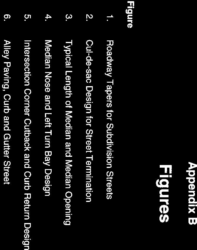

75
CITY OF HUMBLE DESIGN CRITERIA MANUAL FOR WASTEWATER COLLECTION SYSTEMS, WATER LINES, STORM DRAINAGE, AND STREET PAVING
 CITY OF HUMBLE DESIGN CRITERIA MANUAL FOR WASTEWATER COLLECTION SYSTEMS, WATER LINES, STORM DRAINAGE, AND STREET PAVING MARCH 2016 TABLE OF CONTENTS SECTION I GENERAL REQUIREMENTS... 2 SECTION II WASTEWATER
DIVISION 3: SEWER. Improvement Design Standards City of Dundee Oregon. Division 3 : Sewer Page 1
 DIVISION 3: SEWER 3.1 DESIGN CRITERIA A. APPLICABILITY 1. These Design Standards shall govern all construction and upgrading of public sanitary sewer facilities in the City of Dundee and applicable work
Contact the Jurisdictional Engineer for materials allowed by each jurisdiction.
 Design Manual Chapter 3 - Sanitary Sewers 3C - Facility Design 3C-1 Facility Design A. Capacity of Pipe Pipe sizes 15 inches and smaller should carry the peak flow at a depth of no more than 0.67 of the
SEWER SYSTEM DESIGN GUIDELINES
 SEWER SYSTEM DESIGN GUIDELINES PART 1 GENERAL 1.1 GENERAL GUIDELINES A. The following sewer system design guidelines are based on Federal, State and Local health requirements, and the Berkeley County Water
SECTION 4 - DESIGN STANDARDS FOR WATER DISTRIBUTION FACILITIES
 SECTION 4 - DESIGN STANDARDS FOR WATER DISTRIBUTION FACILITIES 4.1 GENERAL REQUIREMENTS 4.1.1 Water and fire protection distribution facilities are to be provided solely for the purpose of supplying potable
This is only a general checklist; please refer to the CVWD Development Design Manual (DDM) for all requirements and regulations.
 for all requirements and regulations.") COACHELLA VALLEY WATER DISTRICT DOMESTIC WATER CHECKLIST Tract/Parcel No: Project Common Name: Developer: Engineer: Engineer Signature: Date: Phone: Phone: Print: This is only a general checklist; please
COACHELLA VALLEY WATER DISTRICT DOMESTIC WATER CHECKLIST Tract/Parcel No: Project Common Name: Developer: Engineer: Engineer Signature: Date: Phone: Phone: Print: This is only a general checklist; please
2. A preconstruction meeting with the TWA s staff is required prior to initiating construction.
 General: 1. Construct utilities in accordance to TWA approved plans and shop drawings. Any deviation from the approved plans shall be approved by the DEVELOPER S ENGINEER and TWA 2. A preconstruction meeting
CITY OF TAMPA WASTEWATER DEPARTMENT TECHNICAL STANDARDS GUIDELINE. FOR CONSTRUCTION OF WASTEWATER FACILITIES July 2014 Version 6
 CITY OF TAMPA WASTEWATER DEPARTMENT TECHNICAL STANDARDS GUIDELINE FOR CONSTRUCTION OF WASTEWATER FACILITIES July 2014 Version 6 2545 Guy N Verger Boulevard, Tampa, FL 33605 www.tampagov.net TECHNICAL STANDARDS
3.0 DESIGN CRITERIA FOR SANITARY SEWER FACILITIES
 3.0 DESIGN CRITERIA FOR SANITARY SEWER FACILITIES All sanitary sewers shall be designed in accordance with these Design Standards, LBWD Rules and Regulations, and to accepted engineering principles. In
CITY OF ASTORIA PUBLIC WORKS ENGINEERING DIVISION ENGINEERING DESIGN STANDARDS FOR IN-FILL DEVELOPMENT
 CITY OF ASTORIA PUBLIC WORKS ENGINEERING DIVISION ENGINEERING DESIGN STANDARDS FOR IN-FILL DEVELOPMENT Adopted by City Council: May 21, 2007 X:\General Eng\DESIGN STANDARDS\Engineering Design Standards
SECTION WATER MAINS CITY OF LEE S SUMMIT, MISSOURI DESIGN CRITERIA
 SECTION 6900 - WATER MAINS CITY OF LEE S SUMMIT, MISSOURI DESIGN CRITERIA 6901 DESIGN CRITERIA A. General 1. The design standards presented in the City of Lee's Summit Design Criteria are the minimum standards
CHAPTER 6. Sanitary Sewer
 CHAPTER 6 Sanitary Sewer A. Introduction All proposed developments, subdivisions, and buildings must have a properly designed and constructed sanitary sewer collection system. The system shall provide
SECTION 3 DRAINAGE. 3-1 General. 3-2 Drainage Ordinances and Legal Requirements
 SECTION 3 DRAINAGE 3-1 General All Drainage plans for proposed development shall be prepared by a Professional Engineer registered in Virginia, except as noted below. Further, their seal and signature
CONSTRUCTION SURVEY. Construction survey includes personnel, equipment, and supplies required for, but not limited to, the following:
 CONSTRUCTION SURVEY PART 1 - GENERAL 1.01 SECTION INCLUDES Construction survey includes personnel, equipment, and supplies required for, but not limited to, the following: A. Construction Survey: 1. Project
Underground Piping for Private Hydrants & Sprinkler Supply Line
 City of Brea Brea Fire Department Fire Prevention 1 Civic Center Circle Phone: (714) 990-7655 Underground Piping for Private Hydrants & Sprinkler Supply Line PURPOSE The provision of adequate water supplies
Construction Documents (CDs) Required Signature Blocks and Standard Notes
 Required Signature Blocks and Standard Notes") Development Services Department 100 N. Wilcox Street, Castle Rock CO 80104 Project Manager 720-733-3582 Construction Documents (CDs) Required Signature Blocks and Standard Notes Revised July 17, 2017 INDEMNIFICATION
Development Services Department 100 N. Wilcox Street, Castle Rock CO 80104 Project Manager 720-733-3582 Construction Documents (CDs) Required Signature Blocks and Standard Notes Revised July 17, 2017 INDEMNIFICATION
TCC/SHORE TRANSIT BUS MAINTENANCE FACILITY - PHASE II
 SECTION 221313 - FACILITY SANITARY SEWERS PART 1 - GENERAL 1.1 RELATED DOCUMENTS A. Drawings and general provisions of the Contract, including General and Supplementary Conditions and Division 01 Specification
SPECIFICATIONS FOR STREET CONSTRUCTION WITHIN THE TOWN OF PLAINVILLE
 SPECIFICATIONS FOR STREET CONSTRUCTION WITHIN THE TOWN OF PLAINVILLE BE IT ORDAINED by the Town Council of the Town of Plainville: SECTION 1. SUBDIVISIONS. All subdivisions hereinafter developed within
Sanitary Sewer Extensions, Lift Stations, and Force Mains Engineering Report Form. I. General Information. 1. Name of Facility:
 Oklahoma Department of Environmental Quality Water Quality Division Phone: 405-702-8100 Construction Permitting Section 707 N. Robinson, OKC, OK 73102-6010 P.O. Box 1677, OKC, OK 73101-1677 Sanitary Sewer
Section V WATER DISTRIBUTION SYSTEM DESIGN GUIDELINES
 Section V WATER DISTRIBUTION SYSTEM DESIGN GUIDELINES A. GENERAL 1. The following water system design guidelines are based on Federal, State and local health requirements and the Hilton Head No. 1 Public
SECTION 8 WATER SUPPLY SYSTEMS
 SECTION 8 WATER SUPPLY SYSTEMS Contents Page 8-1 INTRODUCTION... 1 8-2 INTENT OF WATER SYSTEM IMPROVEMENT STANDARDS... 1 8-3 DEFINITIONS... 1 8-4 APPLICABLE STANDARDS... 1 8-5 IMPROVEMENT AND LANDSCAPE
City of Denton. Water and Wastewater Criteria Manual
 City of Denton Water and Wastewater Criteria Manual February 20, 2002 ii Table of Contents TABLE OF CONTENTS SECTION 1 INTRODUCTION...1 1.1 PURPOSE....1 SECTION 2 PRELIMINARY DESIGN...3 2.1 GENERAL...3
B. Subsurface data is available from the Owner. Contractor is urged to carefully analyze the site conditions.
 SECTION 31 23 33 - TRENCHING, BACKFILLING AND COMPACTION PART 1 - GENERAL 1.1 SCOPE A. This Section specifies the requirements for excavating and backfilling for storm sewer, sanitary sewer, water distribution
INSPECTION AND ACCEPTANCE FOR MAINTENANCE
 Inspection and Acceptance For Maintenance Page 1 (Last revised 6/29/10) INSPECTION AND ACCEPTANCE FOR MAINTENANCE SELECTED LINKS TO SECTIONS WITHIN THIS SPECIFICATION Acceptance Sewer As Built Drwg Example
SECTION CONSTRUCTION SERVICES
 SECTION 01100 CONSTRUCTION SERVICES PART 1 GENERAL 1.01 - Section Includes A. Mobilization. B. Construction Surveys. C. Record Documents. 1.02 Description Of Work A. Mobilization: includes the preparatory
DIVISION 33 - UTILITIES SECTION UTILITY PIPE BORING AND JACKING DIVISION 33 UTILITIES SECTION UTILITY PIPE BORING AND JACKING
 DIVISION 33 UTILITIES PART 1 GENERAL 1.01 SCOPE A. This work shall consist of the underground construction of a pipeline across the state right-ofway, or other facility as indicated on the plans and as
SECTION 19 - TRENCH EXCAVATION, BEDDING AND BACKFILL TABLE OF CONTENTS
 SECTION 19 - TRENCH EXCAVATION, BEDDING AND BACKFILL TABLE OF CONTENTS Section Page 19-1 TRENCH EXCAVATION...19.1 19-1.01 Exploratory Excavation...19.1 19-1.02 Trench Width...19.1 19-1.02.A Storm Drain
CULINARY WATER SYSTEMS
 CULINARY WATER SYSTEMS I. Water system size determination A. The minimum water line size is 8 inch for distribution lines in a residential subdivision. 1. Subdivisions that have a school or church will
PART VII - WATER SYSTEM DESIGN CRITERIA
 PART VII - WATER SYSTEM DESIGN CRITERIA A. Water Distribution, General 1. The water system layout shall be approved by the City Engineer. The fire hydrant layout shall be approved by the Redwood City Fire
Walker County Manufactured Home Rental Community Regulations Infrastructure Development Plan
 A. In accordance with Local Government Code Section 232.007, an Infrastructure Development Plan (IDP) is required for all manufactured home rental communities, as defined in Section A 1.0 E of these regulations,
CURRENT NORTH LAS VEGAS ADDENDA
 SECTION 1 Section 1.01.73 Fire Service Meter ADD: Type I is not approved for installation in the City of North Las Vegas service area. Section 1.01.107 Pressure Reducing Valve (PRV) or Pressure Regulator
CHECKLIST FOR STREETS, INLETS, AND STORM SEWER DESIGN
 CHECKLIST FOR STREETS, INLETS, I. STREET CLASSIFICATION AND DESIGN CRITERIA A. Determine drainage classification for the roadway section using Table 7-1 or Table 7-2. B. Determine the allowable flow depth
Town of New Tecumseth Engineering Design Criteria and Standards for Subdivisions and Capital Works Projects
 2.0 ROADWAYS 2.1 Road Classification 2.1.1 Standard Drawing Classification All Road Widths and Road Allowances shall be designed in accordance with the most recent Town of New Tecumseth Standards: TNT.SD
WASTEWATER SYSTEM STANDARDS
 8.1 SCOPE Wastewater pipelines and appurtenances shall be provided as shown on the plans and as specified herein. Clearing, grubbing, trench excavation and backfill, pipe material, valves, cutting and
PART I DESIGN STANDARDS AND PROCEDURES FOR WATER DISTRIBUTION AND SANITARY SEWER SYSTEMS PRINCE GEORGE COUNTY, VIRGINIA
 PART I DESIGN STANDARDS AND PROCEDURES FOR WATER DISTRIBUTION AND SANITARY SEWER SYSTEMS PRINCE GEORGE COUNTY, VIRGINIA May 2008 1 THIS PAGE INTENTIONALLY LEFT BLANK 2 TABLE OF CONTENTS DESIGN PAGE General
APPLICATION FOR PUBLIC INFRASTRUCTURE PERMIT
 APPLICATION FOR PUBLIC INFRASTRUCTURE PERMIT Engineering Division 550 Landa Street New Braunfels, Texas 78130 (830) 221-4020 1. Subdivision Plat Name: Location Description/ Nearest Intersection: Acreage:
SECTION HIGH DENSITY POLYETHYLENE PIPE AND FITTINGS (PRESSURE PIPE)
") SECTION 02623 HIGH DENSITY POLYETHYLENE PIPE AND FITTINGS (PRESSURE PIPE) PART 1 - GENERAL 1.1 SCOPE OF WORK A. Furnish all labor, materials, equipment and incidentals required and install high density
SECTION 02623 HIGH DENSITY POLYETHYLENE PIPE AND FITTINGS (PRESSURE PIPE) PART 1 - GENERAL 1.1 SCOPE OF WORK A. Furnish all labor, materials, equipment and incidentals required and install high density
SECTION 19 - TRENCH EXCAVATION, BEDDING AND BACKFILL TABLE OF CONTENTS
 SECTION 19 - TRENCH EXCAVATION, BEDDING AND BACKFILL TABLE OF CONTENTS Section Page 19-1 TRENCH EXCAVATION... 19.1 19-1.01 Exploratory Excavation... 19.1 19-1.02 Trench Width... 19.1 19-1.02.A Storm Drain
1. B16.1 Cast Iron Pipe Flanges and Flanged Fittings, Class C 111 Rubber Gasket Joints for Ductile Iron Pressure Pipe and Fittings
 SECTION 33 34 00 SANITARY FORCE MAIN PART 1 GENERAL 1.1 SCOPE OF WORK A. This section specifies the requirements for furnishing and installing sanitary force main and appurtenances. The pipe shall be of
SECTION UTILITY MANHOLES AND STRUCTURES
 SECTION 33 05 14 UTILITY MANHOLES AND STRUCTURES PART 1 GENERAL 1.1 SUMMARY A. Section Includes: 1. Precast reinforced concrete manholes and structures with tongue-and-groove joints with masonry transition
Plan Name Plan No. Submitting Firm Contact Engineer. Review Date ESI Team ENGINEERS AND SURVEYORS INSTITUTE PEER REVIEW CHECKLIST CITY OF ALEXANDRIA
 EROSION AND SEDIMENT CONTROL CHECKLIST (E&S) VIRGINIA EROSION AND SEDIMENT CONTROL HANDBOOK (1 of 2) Item # Description OK NO N/A 1 Limits of clearing and grading match on all appropriate sheets 2 Construction
Zoning Permits 11-1 ZONING PERMITS
 Zoning Permits 11-1 ZONING PERMITS (a) Building or structures shall be started, repaired, reconstructed, enlarged or altered only after a zoning permit has been obtained from the administrator and a building
Storm. Section. B. General Design and Drawing Standards Design
 Section Storm 5 General Plans for the existing stormwater system are maintained in digital and printed form by the City. Copies may be obtained from the Utility Division of the Public Works Department.
1. All underground utilities under railroad tracks shall be encased in a larger pipe or conduit called the casing pipe.
 MTS Jack and Bore Design Criteria Note: For the purposes of this Design Criteria and subsequent Construction Notes, the term Jack and Bore is used generically to refer to a number of trenchless construction
SECTION C1 DUCTILE IRON PIPE AND FITTINGS GENERAL
 SECTION C1 DUCTILE IRON PIPE AND FITTINGS GENERAL This section covers the furnishing and installation of ductile iron water pipe, fittings, thrust restraint and pipe disinfection. Ductile Iron Pipe MATERIALS
SANITARY SEWERS. B. Construct or relocate building sanitary sewer services, stubs, and connections.
 SANITARY SEWERS PART 1 - GENERAL 1.01 SECTION INCLUDES A. Sanitary Sewer Gravity Mains B. Sanitary Sewer Force Mains C. Sanitary Sewer Services 1.02 DESCRIPTION OF WORK A. Construct sanitary sewer gravity
Section Storm Sewers STORM SEWERS PART 1 - GENERAL 1.01 SECTION INCLUDES. A. Storm Sewers. B. Abandonment of Storm Sewers
 STORM SEWERS PART 1 - GENERAL 1.01 SECTION INCLUDES A. Storm Sewers B. Abandonment of Storm Sewers 1.02 DESCRIPTION OF WORK A. Construct storm sewers. B. Abandon storm sewers. 1.03 SUBMITTALS Comply with
SERVICE LINES, METERS AND APPURTENANCES
 AUGUST02 SECTION 02646 SERVICE LINES, METERS AND APPURTENANCES PART 1 - GENERAL 1.1 DESCRIPTION A. This section concerns materials and installation of corporation stops, curb stops, service lines, meters,
Engineering Standards
 Charter Township of Brighton Livingston County, Michigan Adoption Date: December 17, 2007 Brighton Township 4363 Buno Road Brighton, Michigan 48114 P: (810) 229-0550 Table of Contents PURPOSE OF STANDARDS
MANHOLES, VAULTS AND CATCH BASINS SECTION A. Section Soil and Aggregate Materials. C. Section Storm Drainage Systems
 SECTION 02607-1 1.0 GENERAL 1.1 SCOPE: A. This section covers the work necessary for the construction of sanitary and storm system manholes, catch basins, and miscellaneous concrete structures complete.
SECTION STORM DRAINAGE DESIGN, GRADING, AND WATER QUALITY TECHNICAL CRITERIA TABLE OF CONTENTS PAGE 402 STORM DRAINAGE DESIGN CRITERIA 400-1
 CITY OF THORNTON Standards and Specifications Revised: October 2012 SECTION 400 - STORM DRAINAGE DESIGN, GRADING, AND WATER QUALITY TECHNICAL CRITERIA TABLE OF CONTENTS PAGE 401 GENERAL PROVISIONS 400-1
SECTION IV. PIPELINE EXCAVATION AND BACKFILL
 SECTION IV. PIPELINE EXCAVATION AND BACKFILL A. Description of Work B. Surface Types C. Backfill D. Surface Restoration A. DESCRIPTION OF WORK 1. Extent: Excavation of trenches for pipelines shall include
Sanitary Sewer. Section. General.
 Section Sanitary Sewer 3 General. Plans for the existing sewer system are maintained in digital and printed form by the City. Copies may be obtained from the Utility Division of the Public Works Department.
City of Elgin SUBDIVISION FINAL ENGINEERING Engineering Submittal Checklist
 If this is a re-submittal, please provide a point-by-point response to previous review comments, identifying how each comment has been addressed, location in the plan set of the changes made to address
RICHFIELD CITY CONSTRUCTION STANDARDS
 CONSTRUCTION STANDARDS REVISED OCTOBER 2015 Jones & DeMille Engineering, Inc. [0711-211] 1535 South 100 West Richfield, UT 84701 Ph. 435-896-8266 Fax 435-896-8268 1675 South Highway 10 Price, UT 84501
SECTION FACILITY SANITARY SEWERS
 SECTION 22 13 13 FACILITY SANITARY SEWERS PART 1 - GENERAL 1.1 RELATED DOCUMENTS A. Drawings and general provisions of the Contract, including General and Supplementary Conditions and Division 01 Specification
16. Design of Pipeline Structures.
 16. Design of Pipeline Structures. a. General. 1) The following guidelines are for the design of structures for water and sewer pipelines including structural concrete and miscellaneous metals design.
SECTION POLYVINYL CHLORIDE (PVC) WATERLINE
 WATERLINE") SECTION 02632 POLYVINYL CHLORIDE (PVC) WATERLINE PART 1 - GENERAL 1.01 SCOPE OF WORK A. Furnish all labor, materials, equipment, and incidentals required, and install polyvinyl chloride (PVC) waterline,
SECTION 02632 POLYVINYL CHLORIDE (PVC) WATERLINE PART 1 - GENERAL 1.01 SCOPE OF WORK A. Furnish all labor, materials, equipment, and incidentals required, and install polyvinyl chloride (PVC) waterline,
SECTION TRENCHING & BACKFILLING
 SECTION 02225 - TRENCHING & BACKFILLING 1.0 GENERAL 1.1 Work included in this Section includes trenching and backfilling for underground pipelines and related structures only. 1.2 Reference Specifications
SPECIFICATION : BORING AND JACKING
 SPECIFICATION 330524: BORING AND JACKING PART 1.0 GENERAL 1.1 DESCRIPTION 1.1.1 The work of this specification includes all labor, machinery, construction equipment and appliances required to perform in
ENGINEERING DESIGN STANDARDS
 CITY OF SOUTHFIELD DEPARTMENT OF PUBLIC WORKS ENGINEERING DIVISION ENGINEERING DESIGN STANDARDS APPROVED BY: Gary M. Mekjian, P.E. City of Southfield Director of Public Works Dated: Oct. 1, 2007 Revised:
Rural Servicing Guidelines
 Rural Servicing Guidelines for Low-Pressure Sanitary Sewer System and Trickle Feed Water Distribution System FOREWORD This manual is intended to provide information to Developers, Engineering and Geotechnical
DESIGN OF SEWER SYSTEMS
 Wastewater Engineering (MSc program) DESIGN OF SEWER SYSTEMS Prepared by Dr.Khaled Zaher Assistant Professor, Public Works Engineering Department, Faculty of Engineering, Cairo University 1. Sewer Materials
ARTICLE XII RECREATIONAL VEHICLE PARK REGULATIONS
 ARTICLE XII RECREATIONAL VEHICLE PARK REGULATIONS ARTICLE XII RECREATIONAL VEHICLE PARK REGULATIONS Section 1201 Applicability For the purpose of this Article, recreation vehicles and recreational vehicle
3.1 Introduction: Design Responsibility and Applicability of Requirements
 SECTION 3 Sewer Design and Construction 3.1 Introduction: Design Responsibility and Applicability of Requirements The design and construction requirements for sewer collection systems included in this
SECTION TAPPING SLEEVES AND VALVES
 SECTION 33 12 16.17 TAPPING SLEEVES AND VALVES PART 1: GENERAL 1.01 SCOPE Furnish, install and test all tapping sleeves, tapping valves, and tapping saddles as shown on the Drawings. 1.02 RELATED WORK
All service lines shall conform to the following requirements:
 505 WATER SERVICE INSTALLATION 505.1 DEFINITION A service line is comprised of the piping and related appurtenances including the connection installed from the Des Moines Water Works water main to the
SECTION STORM UTILITY DRAINAGE PIPING PART 1 - GENERAL 1.1 SUMMARY 1.2 SUBMITTALS 1.3 PROJECT CONDITIONS
 SECTION 334100 - STORM UTILITY DRAINAGE PIPING PART 1 - GENERAL 1.1 SUMMARY Section Includes: 1. Pipe and fittings. 2. Drain Basin. 3. De-chlorination tablet feeder. 4. Non-pressure transition couplings.
TOWN OF MOUNT PLEASANT WESTCHESTER COUNTY, NEW YORK
 TOWN OF MOUNT PLEASANT WESTCHESTER COUNTY, NEW YORK COST EVALUATION FOR ROLLING HILLS AREA WATER MAIN EXTENSION PROFESSIONAL CONSULTING, LLC. Octagon 10, Office Center 1719 Route 10, Suite 225 Parsippany,
ENGINEERING DESIGN & IMPROVEMENT STANDARDS
 ENGINEERING DESIGN & IMPROVEMENT STANDARDS 2016 Prepared by: Engineering Division For latest edition of these Improvement Standards, refer to City of Visalia website at: www.visalia.city/engineeringdocuments
SECTION EXCAVATION AND BACKFILL FOR UTILITIES AND STRUCTURES
 SECTION 02215 EXCAVATION AND BACKFILL FOR UTILITIES AND STRUCTURES PART 1 - GENERAL 1.1 DESCRIPTION: This section includes materials, testing, and installation of earthwork for excavations, fills, and
PASSAIC COUNTY TECHNICAL INSTITUTE CCA 1422 NEW S.T.E.M. BUILDING 2017
 SECTION 02630 - STORM DRAINAGE PART 1 - GENERAL 1.1 RELATED DOCUMENTS A. Drawings and general provisions of the Contract, including General and Supplementary Conditions and Division 01 Specification Sections,
SECTION HIGH DENSITY POLYETHYLENE PIPE AND FITTINGS
 SECTION 02620 PART 1 GENERAL 1.1 SCOPE OF WORK A. Furnish all labor, materials, equipment, and incidentals required to install High Density Polyethylene (HDPE) pressure pipe, fittings, and appurtenances
Engineer s Packet. Water and Sewer
 Engineer s Packet Water and Sewer The White House Utility District engineer s packet has been created to help streamline the plan review and plan approval of projects within the White House Utility District
SECTION EXCAVATING, BACKFILLING, AND COMPACTION FOR UTILITIES
 SECTION 02221 EXCAVATING, BACKFILLING, AND COMPACTION FOR UTILITIES PART 1 GENERAL 1.01 SUMMARY A. Related Sections: 1. 02200 - Earthwork. 2. 02660 - Water Systems. 3. 02720 - Storm Drainage System. 4.
Classifications of Improvements and Definitions
 Design Manual Chapter 1 - General Provisions Table of Contents TOC Table of Contents Chapter 1 - General Provisions 1A General Conditions 1A-1---------------------------------General Conditions A. Purpose.....
A. Codes and Standards that are standard at the University. C. Coordinate cleanout locations with Architect.
 PART 1: GENERAL 1.01 Purpose: A. This standard is intended to provide useful information to the Professional Service Provider (PSP) to establish a basis of design. The responsibility of the engineer is
Engineering Design Center. Standard Drawings. 1st Edition -January 2016
 Engineering Design Center Standard Drawings 1st Edition -January 2016 Golden State Water Company Standard Drawings 1/11/2016 Table of Contents PART A STANDARD DRAWINGS Section I Pipeline Construction P-1
SPECIAL CONDITIONS FOR PIPE JACKING (PJ) October, 2006
 October, 2006") Michigan Department Of Transportation 3703C (11/06) 1 Materials 1.1 Pipe SPECIAL CONDITIONS FOR PIPE JACKING (PJ) October, 2006 Page 1 of 5 The type of pipe used for the pipe jacking method shall be capable
Michigan Department Of Transportation 3703C (11/06) 1 Materials 1.1 Pipe SPECIAL CONDITIONS FOR PIPE JACKING (PJ) October, 2006 Page 1 of 5 The type of pipe used for the pipe jacking method shall be capable
GUIDELINE FOR PROVIDING WATER AND SEWER SERVICE TO DEVELOPER PROJECTS AND PUBLIC OR PRIVATE PROPERTIES
 Public Works Department Water & Wastewater Services WATER & WASTEWATER ENGINEERING DIVISION 2555 West Copans Road Pompano Beach, Florida 33369 954-831-0745 FAX 954-831-0798/0925 GUIDELINE FOR PROVIDING
SECTION ALUMINUM GATES
 P.O. Box 1058 370 South Athol Rd. Athol, Massachusetts 01331 Phone: (978) 249-7924 Fax: (978) 249-3072 SECTION ALUMINUM GATES PART 1 GENERAL 1.01 SCOPE OF WORK A. The CONTRACTOR shall furnish all labor,
REQUIREMENTS FOR WORK WITHIN ROAD RIGHTS-OF-WAY IN UNION COUNTY
 REQUIREMENTS FOR WORK WITHIN ROAD RIGHTS-OF-WAY IN UNION COUNTY The requirements contained herein are established to provide for orderly and systematic use of the county road rights-of-way within Union
Construction Specifications
 Exhibit A Construction Specifications January 2006 Amended August, 18 2008 Amended November 1, 2011 Town of Fishers, Indiana Table of Contents SECTION 1. INTRODUCTION 1.1 FORWARD... 1.2 CONTACT INFORMATION...
STANDARD SPECIFICATIONS SECTION BORING AND JACKING. A. Section includes requirements for boring and jacking casing pipe.
 STANDARD SPECIFICATIONS SECTION 02445 BORING AND JACKING PART 1 GENERAL 1.1 DESCRIPTION A. Section includes requirements for boring and jacking casing pipe. 1.2 DEFINITIONS A. Carrier Pipe: Sewer or water
***************************************************************************************************************
 02720 STORM DRAINAGE SYSTEM *************************************************************************************************************** SPECIFIER: CSI MasterFormat 2004 number 33 40 00. ***************************************************************************************************************
TRENCHLESS CONSTRUCTION (BORING, JACKING, AND TUNNELING)
") PART 1 - GENERAL TRENCHLESS CONSTRUCTION (BORING, JACKING, AND TUNNELING) 1.01 SECTION INCLUDES A. Trenchless Installation of Carrier Pipe with Casing Pipe B. Trenchless Installation of Carrier Pipe without
PART 1 - GENERAL TRENCHLESS CONSTRUCTION (BORING, JACKING, AND TUNNELING) 1.01 SECTION INCLUDES A. Trenchless Installation of Carrier Pipe with Casing Pipe B. Trenchless Installation of Carrier Pipe without
DARTMOUTH COLLEGE DESIGN January 3, 2012 & CONSTRUCTION GUIDELINES
 SECTION 15420 DRAINAGE AND VENT SYSTEMS PART 1 DESIGN DIRECTIVES 1.1 DESIGN CRITERIA A. All cleanouts above finished (accessible and non-accessible) ceilings shall be extended to the floor above. B. Do
Specifications for Electrical Underground Residential Distribution Systems
 Specifications for Electrical Underground Residential Distribution Systems Specification DDS-2 Revision 13, February 2010 ONCOR ELECTRIC DELIVERY COMPANY SPECIFICATIONS FOR ELECTRICAL UNDERGROUND RESIDENTIAL
SECTION MANHOLES AND STRUCTURES. A. Section Includes: 1. Manholes for water, storm drain and sanitary sewer systems.
 SECTION 33 05 13 MANHOLES AND STRUCTURES PART 1 GENERAL 1.1 SUMMARY A. Section Includes: 1. Manholes for water, storm drain and sanitary sewer systems. B. Related Sections: 1. Section 03 20 00 - Concrete
SECTION 820 PUMP STATION DEMOLITION AND SITE RESTORATION
 820-1 SCOPE OF WORK: SECTION 820 PUMP STATION DEMOLITION AND SITE RESTORATION a. Furnish all labor, materials, equipment, and incidentals required for demolition and/or removal and disposal of existing
Summary of the 2011 Changes
 The following is a list of amendments to the Residential Site Improvement s, N.J.A.C. 5:21, adopted in 2011. The Notice of Adoption of these changes appeared in the New Jersey Register on May 16, 2011.
RESIDENTIAL CONSTRUCTION New Dwellings and Additions
 How to Obtain a Building Permit For RESIDENTIAL CONSTRUCTION New Dwellings and Additions MIAMI COUNTY, KANSAS CODE SERVICES DEPARTMENT 201 South Pearl Street, Suite 201 Paola, Kansas 66071-1777 Phone:
CHAPTER 3 - PRESSURE IRRIGATION
 CHAPTER 3 - PRESSURE IRRIGATION 3.1 GENERAL This division covers furnishing and installing pressure pipe as shown on the Drawings or established in the field, and all flushing, testing, repairing, as required
Engineering Plan Submittal Requirements. Revised: October 6, 2017
 Engineering Plan Submittal Requirements Revised: October 6, 2017 Page 1 of 11 Introduction: These Engineering Plan Submittal Requirements are intended to standardize City requirements for civil engineering
City of Wentzville. Standard Specifications and Construction Details Amendment List
 Amendment No. 1 Standard Specifications and Construction Details Amendment List Date: September 21, 2009 Subject: SCD 700.23 - Residential Entrance Layout and drawing revised to more clearly show the location
SECTION WASTEWATER COLLECTION SYSTEMS TABLE OF CONTENTS
 SECTION 07000 WASTEWATER COLLECTION SYSTEMS TABLE OF CONTENTS 07010 GRAVITY SEWERS A. Design B. Materials C. Sewer Main Installation D. Pipe Identification and Marking 07020 MANHOLES A. Design B. Materials
City of Jacksonville Development Guide Building Permits
 City of Jacksonville TX City of Jacksonville Development Guide Building Permits A publication to help understand the Building Permit process in the City Jacksonville. Building Department 2011 J Revised
SECTION 19 - TRENCH EXCAVATION, BEDDING AND BACKFILL TABLE OF CONTENTS
 SECTION 19 - TRENCH EXCAVATION, BEDDING AND BACKFILL TABLE OF CONTENTS Section Page 19-1 TRENCH EXCAVATION... 19-1 19-1.01 Exploratory Excavation... 19-1 19-1.02 Trench... 19-1 19-1.02.AStorm Drain Pipe...
SECTION CHAIN LINK FENCES AND GATES (GALVANIZED) A. Fence framework, fabric, gates, and accessories.
 A. Fence framework, fabric, gates, and accessories.") SECTION 02830 CHAIN LINK FENCES AND GATES (GALVANIZED) 1.0 GENERAL 1.1 Section Includes A. Fence framework, fabric, gates, and accessories. B. Excavation for post bases; concrete footing for posts. C.
SECTION 02830 CHAIN LINK FENCES AND GATES (GALVANIZED) 1.0 GENERAL 1.1 Section Includes A. Fence framework, fabric, gates, and accessories. B. Excavation for post bases; concrete footing for posts. C.
SITE SERVICES GUELPH TRANSIT OPERATIONS & MAINTENANCE SECTION WATSON ROAD FACILITY PAGE 1 OF 6 WATER RECLAMATION PROJECT JUNE 2013
 WATSON ROAD FACILITY PAGE 1 OF 6 PART 1 GENERAL 1.1 Description The work covered by this Section includes all labour, materials, equipment, and supervision necessary to complete the site services as shown