Walls generally range from 600 to 1500 mm thickness, in wide between 2000 and 3500 mm and can be excavated to depths of 60m or more.
|
|
|
- Winfred Hunter
- 6 years ago
- Views:
Transcription


1 TECHNOLOGY Diaphragm walls
 until the mud is replaced by concrete, after the steel cage")
2 Diaphragm walls are one of the most important technologies of special foundation engineering. A diaphragm wall is constructed using a trench excavated in ground and supported by a mud fluids (typically bentonite or polimer mud) until the mud is replaced by concrete, after the steel cage installation. Walls generally range from 600 to 1500 mm thickness, in wide between 2000 and 3500 mm and can be excavated to depths of 60m or more.

3 Can be installed in all soil conditions and through rock Used in high water table conditions without excessive dewatering Low costs and speed of construction for temporary and permanent soil support

4 Technology Diaphragm walls are rectangular-section excavations with a complete ground asportation that is made in situ. The result is an underground concrete wall. They are essentially retention walls, which are constructed for instance at wharfs. A rectangular-section tool is generally used to remove the soil, thus creating a rectangular excavation. Furthermore the rectangles making up the wall must be interlocked to ensure structural endurance and water tightness. The diaphragm wall panel construction entails three steps: the construction of guide wall, the panel excavation (demolition removal - stabilization), and the construction phase (reinforcing cage casting curing). To build a continuous diaphragm wall the primary panels are firstly constructed and spaced at a distance slightly larger than the panel width. The secondary panels are built in the empty spaces between the primary ones.


5 Construction stages Diaphragm wall construction requires that a proper sequence of works is followed. A rectangular-section tool is generally used to remove the soil, thus creating a rectangular excavation. The main digging tool for panels is the grab, which shall have the same size of the component it shall dig. Holes are stabilized with bentonite slurry. Concreting is performed using the tremie technique as for castin-place piles. Guide wall installation Prior to diaphragm wall excavation is necessary to construct two temporary parallel concrete beams to guide the excavation tool and to stabilize the upper. Guide walls are cast-in-place or pre-cast lightly reinforced concrete elements. Guide walls maintain the horizontal alignment and wall continuity of a diaphragm wall while are adopted to avoid superficial soil collapse, to mark the panels position and to support the steel cages during the concrete aging. This temporary support is important as the slurry levels vary during construction and the wall tends to be unstable. Equally important, guide walls help guide the diaphragm wall grabs vertically and aid in the positioning of the final structure. The dimensions and shape of the guide walls may change depending on the nature of the surface soil. As it happens in bored piles, the bentonite slurry inside the excavation hole shall always be kept some meters above the height of the water table. In some special cases where the water table is very close to the surface and the soil has poor mechanical properties, the guide walls may be built on a higher height compared to the ground plane to preserve the above mentioned height difference.


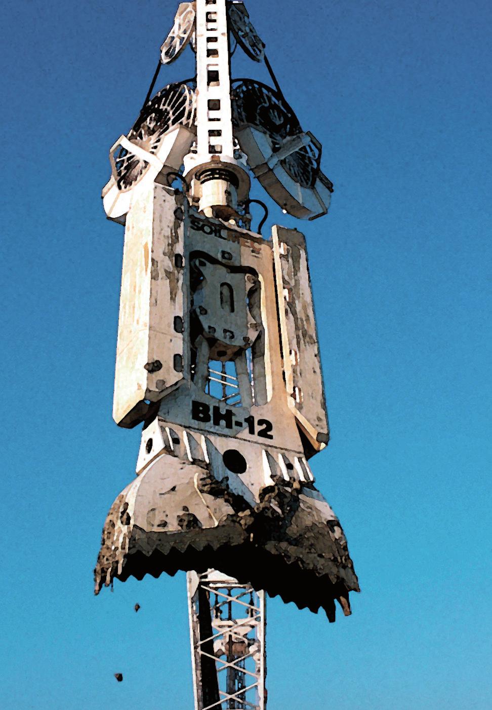
6 Construction stages Panel excavation The single panel is excavated downward using grab until reaching the required level. The trench is prevented from collapsing during excavation, reinforcing and casting by the use of supporting bentonite slurry. The slurry forms a thick deposit (the cake) on the walls of the trench which balances the inward hydraulic forces and prevents water flow into the trench. A slurry made of polymers can also be used. Grabs are diaphragm wall digging tool consisting of two jaws which can open and close to collect cuttings and take them out of the excavated trench. Jaw outer profiles are fitted with teeth to cut the soil. The excavation work cycle starts with the open grab rested on the ground: thanks to the tool weight and speed, the teeth penetrate the soil. By activating the closing system, the grab excavates the soil and keeps part of it inside the jaws. Teeth arrangement on the jaws is usually an odd number of teeth on one jaw, and an even number of teeth on the other, to ensure perfect closing. The jaws asymmetrical configuration tends to deviate from straightness and for this reason the grab is not always used in the same direction, but alternately in both directions: every time the grab is lowered into the excavation, it is rotated by 180. The grab is lifted with the jaws closed and the soil is discharged in a designated area. The work cycle is repeated a number of times until excavation has been completed. The primary panels are excavated first and Secondary panels are constructed between primary diaphragm wall panels. Once the panel is excavated, prior to concreting, the supporting slurry fluid must be cleaned and refreshed so its density, sand content, viscosity and PH are within specified levels.


7 Construction stages Panel construction One of the most delicate issues in the diaphragm wall construction is represented by the waterproof joints between panels. One of the main functions of the diaphragm wall, in addition to supporting the soil up to the final excavation inside it, is preventing settlement of buildings and superstructures beside the excavation and also guaranteeing the wall s waterproofness. The Joints are available in various type and their choose depends on the excavating equipment as much as contractor preference. Once the bottom of the panel is reached and cleaned, the reinforcement cage can be lowered into position. The reinforcement cages have a significant size and weight, as a general rule, the cage is built by laying the components (of adequate length) on the ground then connecting them together. If there is the need for building the cage in separate sections, said sections shall be properly connected using a method approved by the engineer. The concrete is placed through a vertical steel pipe with an open, funnel-shaped upper end named tremie. With the tremies, concreting of a diaphragm wall starts from the bottom and the tremies are lifted progressively as the concrete level rises. Simultaneously with placing concrete, slurry is pumped from the panel to be refreshed and re-used in the next panel excavation. STAGE 1 Excavation STAGE 2 Bentonite mud desanding STAGE 3 Placing of reinforcement STAGE 4 Pouring of concrete


8 Technology There are three main types of joint design used for diaphragm walls: stop and pipes Stop end pipes The steel pipes are installed at both panel fronts before concreting. The pipes rest on the excavation bottom and match the circular shape of the panel fronts. The concrete injected takes the shape of the stop end pipes, the latter are filled with bentonite slurry and the panel has concave fronts. Once primary panels have been constructed and the stop end pipes removed, secondary panels are executed. Once secondary panels have been fully excavated, concreting can start. Concrete fills the semicircular joints and provides a very good interlock. Disposable pipes Pipes are in PVC; they are fixed to the cage and lowered to rest on the bottom. During concreting, the whole section is filled by concrete, except for the pipes which remain full of bentonite slurry. The result is a panel with two holes. After excavating the secondary panels, by using a dedicated tool the concrete seam separating the pipe from the secondary panel and the pipes are demolished. As a result, a round indentation is created in the primary panel. When concrete is cast in the secondary panel, it fills the recess and creates a joint with the primary panel. primary secondary primary secondary pipes primary secondary primary


9 Technology sheet pipes primary excavation digging sheet piling removal installation of sheet piling with water stop digging and secondary panel primary panel and concreting secondary panel concreting Sheet piling With this method, a steel sheet pile is driven into the primary panel, before concrete is cast. After concreting has been completed, the concrete on the fronts of the panel takes on the shape of the sheet pile and a recess is created. When concrete has hardened enough to keep its shape, sheet piles are extracted. Afterward the secondary panel is excavated using a suitable tool to copy the recess of the primary panel and remove soil from this area. When concreting, concrete fills the recess and provides a good interlock between the panels. This technique allows for the insertion of plastic elements called water stops between the panels, in order to guarantee increased water tightness. The Milan joint Trevi Group has developed a special system during the works for the Milan Underground line 3 project in 1985, a system which has been called Milan joint because of its origin. The joint is built using a PVC pipe, connected to the primary panel cage. The bottom end of the pipe is closed by a holed cap so as to allow the bentonite slurry to flow in the tube thus preventing the walls of the tube from collapsing due to the pressure the concrete, rising up during the excavation, will exercise on the tube walls. After excavation of the secondary panels has been completed, a cleaner is mounted on the grab; the grab is then lowered and the cleaner breaks the wall of the PVC pipe. This way the concrete penetrates into the pipe s cross-section thus creating a waterproof joint.


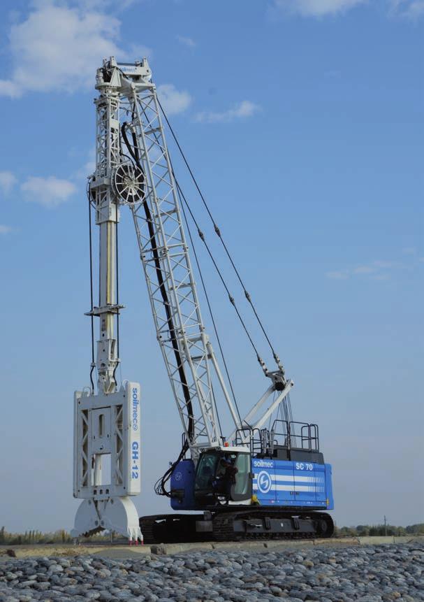
10 Job site logistics A typical jobsite constructing Diaphragm walls through slurries will use the following equipment: A crane equipped with grab A plant to produce the slurry A plant to desand the slurry A service crane to position steel reinforcement cage in the borehole and to handle the tremie pipes to cast the concrete Desander Bentonite preparation plant Auxiliary crane Crane with grab
 and to widths of 600 to 1500 mm.")

11 Technology advantages The main advantage of Diaphragm wall technology are listed below: Can be constructed in a very wide range of soil types and rocks. Diaphragm walls can be constructed to depths of 60 meters (and above) and to widths of 600 to 1500 mm. Diaphragm walls tend to be used for retaining very deep excavations as they can be designed to take very high structural loads. The water tight walls formed can be used as permanent structural walls. Reduced number of joints in the wall which ultimately improves the walls water tightness. Work may be carried out right against existing structures and the line of wall may be adjusted to any shape in plan. Diaphragm wall construction is relatively quiet, and minimum noise and vibration levels make it suitable for construction in urban areas. Can be used as top-down method in order to optimize the sequence of operations to be performed in densely-populated inner city areas.

12

 TELESCOPIC EXTERNAL GUIDE GRAB BODY SIDE GUIDES GRAB OPERATION")
13 Soilmec Equipment 1 2 Since 1974, with the first BHP hydraulic grab, Soilmec is a benchmark point in the field of the diaphragm wall technology executed by grabs. Today Soilmec produces and distributes the GC line, mechanical cable operated grab and the hydraulic lines BH and GH that allow excavation of a wide range of panel dimensions. Both BH and GH grabs can be equipped with the innovative Rotograb Kelly System developed by Soilmec to meet the demand of the front of wall application SPECIAL CATHEAD HYDRAULIC REVOLVING GEAR MOTORS +/- 180 (360 USING ROTOGRAB) TELESCOPIC EXTERNAL GUIDE GRAB BODY SIDE GUIDES GRAB OPERATION CYLINDER JAWS HYDRAULIC COILERS 7


14 Soilmec Equipment Grabs Range Mechanical cable operated and hydraulic grabs for diaphragm wall technology. Model BH-8 GH-12/ GH-12R GH-15/ GH-15R GC-11 GC-16 Max depth 75 m 75 m 75 m depending on crane depending on crane Weight (approx.) 8 t 12.5 t 15.2 t 11 t 16 t Panel thickness 350/800 mm 500/1200 mm 600/1500 mm 500/1200 mm 800/1500 mm Panel width 2000/3000 mm 2500/4200 mm 2800/4200 mm 2500/3000 mm 2800/3500 mm Type hydraulic hydraulic hydraulic mechanical mechanical Jaws clousure cylinder cylinder cylinder rope rope
15

16 Diaphragm Walls /2016 All technical data are purely indicative and subject to change without notice This brochure has been edited and distributed by SOILMEC Spa. The present document cancels and override any previous ones. This brochure shall not be distributed, reproduced or exhibited without SOILMEC Spa. authorization in accordance with to SOILMEC web site disclaimer condition. SOILMEC Spa distributes machinery and structures all over the world, supported by SOILMEC Spa subsidiary companies and dealers. The complete Soilmec network list is available on the web site
Diaphragm wall Construction
 Diaphragm wall Construction Diaphragm wall is a continuous wall constructed in ground in to facilitate certain construction activities, such as: a) As a retaining wall b) As a cut-off provision to support
TECHNOLOGY. Continuous Flight Auger
 TECHNOLOGY Continuous Flight Auger CFA (Continuous Flight Auger) technology joins the advantages of driven piles with the versatility of application of drilled piles. Moreover, a wide range of diameters
DIAPHRAGM WALLS, CUT-OFF WALLS AND SLURRY WALLS
 DIAPHRAGM WALLS, CUT-OFF WALLS AND SLURRY WALLS Implenia Spezialtiefbau GmbH Robert Bosch Straße 25 D-63225 Langen Phone: +49 6103 988 345 Fax: +49 6103 988 277 Email: info.spezialtiefbau@implenia.com
NEW PERFORMANCE CRITERIA FOR FRESH TREMIE CONCRETE
 NEW PERFORMANCE CRITERIA FOR FRESH TREMIE CONCRETE Karsten Beckhaus (1), Martin Larisch (2), Habib Alehossein (3,4) (1) BAUER Spezialtiefbau GmbH, Deutschland (2) Keller Australia Pty Ltd, Australia (3)
Soil Mechanics Lateral Earth Pressures page Lateral Earth Pressures in case of inclined ground surface or friction at wall-ground interface
 Soil Mechanics Lateral Earth Pressures page 9 7.6 Lateral Earth Pressures in case of inclined ground surface or friction at wall-ground interface By now, we have considered the wall as perfectly smooth
GeoEng2000 An International Conference on Geotechnical & Geological Engineering
 GeoEng2000 An International Conference on Geotechnical & Geological Engineering 19-24 November 2000 Melbourne Exhibition and Convention Centre Melbourne, Australia Barrettes : A versatile foundation for
Wet Speed-Mixing WSM - Soil Mixing Procedure in Twinmix Design
 Wet Speed-Mixing WSM - Soil Mixing Procedure in Design Method description WSM - a fast alternative for shoring applications What is WSM? WSM stands for Wet Speed-Mixing, a fast soil mixing procedure. The
SCOPE OF WORK FOR PILING JOB
 SCOPE OF WORK FOR PILING JOB 1.0 PURPOSE This document defines the scope of works and specific requirements for the tank pad construction including pile foundation system for the proposed tanks at Wadala
Pipe Jacking/Microtunnelling. Dr. Mark Knight. Centre for Advancement of Trenchless Technologies (CATT) University of Waterloo.
 University of Waterloo.") Pipe Jacking/Microtunnelling Dr. Mark Knight Centre for Advancement of Trenchless Technologies (CATT) University of Waterloo 1 New Installations New Installations Non-Steering Methods Steering Methods
Pipe Jacking/Microtunnelling Dr. Mark Knight Centre for Advancement of Trenchless Technologies (CATT) University of Waterloo 1 New Installations New Installations Non-Steering Methods Steering Methods
h Installation Manual
 h Installation Manual 1 General Information The installation of HOBAS GRP Pipes is subject to applicable standards and guidelines such as EN 1610 and ISO/ TS 10465-1. Correct installation always requires
SECTION EXCAVATING, BACKFILLING, AND COMPACTION FOR UTILITIES
 SECTION 02221 EXCAVATING, BACKFILLING, AND COMPACTION FOR UTILITIES PART 1 GENERAL 1.01 SUMMARY A. Related Sections: 1. 02200 - Earthwork. 2. 02660 - Water Systems. 3. 02720 - Storm Drainage System. 4.
ROTARY DRILLING TECHNIQUES LARGE DIAMETER
 INTRODUCTION This paper presents details about large diameter rotary drilling techniques typically employed in the civil engineering industry. These techniques have also been applied to the resources /
Combined Pile Foundation System for a Residential Complex
 Combined Pile Foundation System for a Residential Complex Alvin K.M. Lam, Geotechnical Engineer, Ove Arup & Partners Hong Kong Limited, Hong Kong, China; email: alvin.lam@arup.com Daman D.M. Lee, Civil
TRENCHLESS CONSTRUCTION (BORING, JACKING, AND TUNNELING)
") PART 1 - GENERAL TRENCHLESS CONSTRUCTION (BORING, JACKING, AND TUNNELING) 1.01 SECTION INCLUDES A. Trenchless Installation of Carrier Pipe with Casing Pipe B. Trenchless Installation of Carrier Pipe without
PART 1 - GENERAL TRENCHLESS CONSTRUCTION (BORING, JACKING, AND TUNNELING) 1.01 SECTION INCLUDES A. Trenchless Installation of Carrier Pipe with Casing Pipe B. Trenchless Installation of Carrier Pipe without
S.No Description Unit Quantity Rate (Rs) Amount (Rs)
 Amount (Rs)") , S.No Description Unit Quantity Rate (Rs) Amount (Rs) 1 2 Vertical load testing of piles in accordance with IS 2911 (Part IV) including installation of loading platform by Kentledge method and preparation
, S.No Description Unit Quantity Rate (Rs) Amount (Rs) 1 2 Vertical load testing of piles in accordance with IS 2911 (Part IV) including installation of loading platform by Kentledge method and preparation
CF50/100 KW TURBINE ACCESS ROAD, CRANE PLATFORM, CONCRETE, AND LIFTING SPECIFICATIONS C&F GREEN ENERGY REVISION PREPARED BY APPROVED BY DATE
 CF50/100 KW TURBINE ACCESS ROAD, CRANE PLATFORM, CONCRETE, AND LIFTING SPECIFICATIONS C&F GREEN ENERGY REVISION PREPARED BY APPROVED BY DATE 001 First Draft W Hession 12.02.2014 Introduction This document
SECTION A1 EXCAVATION AND BACKFILL GENERAL
 SECTION A1 EXCAVATION AND BACKFILL GENERAL The work under this section shall include all excavation to such width and depth as shown on the drawings, specified herein, or ordered by the Engineer. Such
1. All underground utilities under railroad tracks shall be encased in a larger pipe or conduit called the casing pipe.
 MTS Jack and Bore Design Criteria Note: For the purposes of this Design Criteria and subsequent Construction Notes, the term Jack and Bore is used generically to refer to a number of trenchless construction
HEKAPLAST. PE-HD twin wall cable ducts and cable protection pipes for underground installation. Corrugated and Twin Wall Pipes of Plastics
 HEKAPLAST PE-HD twin wall cable ducts and cable protection pipes for underground installation HEGLER HEKAPLAST III/ HEKAPLAST: Twin wall cable ducts or cable protection pipes to DIN 696, manufactured from
UNDERPINNING A CRANE FOUNDATION
 UNDERPINNING A CRANE FOUNDATION Donald R. McMahon, P.E., McMahon & Mann Consulting Engineers, P.C., Buffalo, New York, USA Andrew J. Nichols, P.E., McMahon & Mann Consulting Engineers, P.C., Buffalo, New
Building pit District adjacent to St.Katharinenkirche Hamburg, Germany
 Building pit District adjacent to St.Katharinenkirche Hamburg, Germany Implenia Spezialtiefbau GmbH Infrastructure - Northern Branch Heidenkampsweg 81 D-20097 Hamburg GERMANY T +49 40 229257-201 F +49
Topic: Site Formation
 Topic: Site Formation Presentation prepared by Raymond Wong February 2006 Purpose of site formation is to prepare a piece of land in order to: Accommodate building/s or other facilities which will be placed
PAUL ZICK, PE NORTH SHORE CONSTRUCTORS JV
 NORTH SHORE CONNECTOR TUNNELS AND STATION SHELL LIGHT RAIL PROJECT PAUL ZICK, PE NORTH SHORE CONSTRUCTORS JV North Shore Connector Alignment 7300 lf Extension to existing 25 mile system 18 Contracts $435
Construction Planning, Equipment, and Methods PILES AND PILE-DRIVING EQUIPMENT
 CHAPTER Construction Planning, Equipment, and Methods PILES AND PILE-DRIVING EQUIPMENT Sixth Edition A. J. Clark School of Engineering Department of Civil and Environmental Engineering 19 By Dr. Ibrahim
SITE INVESTIGATION. Foundation Engineering
 SITE INVESTIGATION Assist. Prof. Berrak TEYMUR Foundation Engineering Analysis Design Construction As a foundation engineer, you need to consider geotechnical/structural issues (involves geology, subsurface
The Technical and Contractual Matters of Bored Piling Works. By Wallace Yeung Vibro (H.K.) Ltd.
 Ltd.") The Technical and Contractual Matters of Bored Piling Works By Wallace Yeung Vibro (H.K.) Ltd. What is large diameter bored pile? How to construct a large diameter bored pile? Its advantages and limitation
The Technical and Contractual Matters of Bored Piling Works By Wallace Yeung Vibro (H.K.) Ltd. What is large diameter bored pile? How to construct a large diameter bored pile? Its advantages and limitation
CHANGES IN 2006 SPECIFICATIONS SECTION 804 DRIVEN PILES SECTION 814 DRILLED SHAFTS
 CHANGES IN 2006 SPECIFICATIONS SECTION 804 DRIVEN PILES SECTION 814 DRILLED SHAFTS 2006 LADOTD ENGINEERING CONFERENCE Kim Martindale Garlington, P.E. Pavement & Geotechnical Services February 13, 2007
Hydraulic Excavators
 Chapter 8 Hydraulic Excavators Hydraulic excavators are designed to excavate below the ground surface on which the machine rests. These machines have good mobility and are excellent for general-purpose
ITEM D-701 PIPE FOR STORM DRAINS AND CULVERTS
 ITEM D-701 PIPE FOR STORM DRAINS AND CULVERTS 701-1 DESCRIPTION 701-1.1 This item shall consist of the construction of pipe culverts, and storm drains, removal of existing storm pipes, connections to existing
SPECIFICATION FOR REINFORCED SOIL WALL
 SPECIFICATION FOR REINFORCED SOIL WALL 1.0 EXTENT OF WORK The work shall consist of Reinforced Soil walls built in accordance with this specification and in conformity with the lines, levels and details
Oweninny Wind Farm. Oweninny Environmental Impact Statement Appendix 5. Turbine Foundation Construction Method Statement
 Oweninny Wind Farm Oweninny Environmental Impact Statement Appendix 5 Turbine Foundation Construction Method Statement Copyright ESB International Limited, all rights reserved. Farm Contents 1 Introduction
Concrete Slab-on-Ground
 Concrete Slab-on-Ground This training package provides information on concrete slab-on-ground construction, including reinforcement, formwork, mix, placement and curing, for village infrastructure and
SAMPLE SPECIFICATION for CROSSHOLE SONIC LOGGING (CSL) September 2015
 September 2015") SAMPLE SPECIFICATION for CROSSHOLE SONIC LOGGING (CSL) September 2015 Note: This sample specification contains recommended or typical quantities in parenthesis, in the format (quantity); the specifying
SAMPLE SPECIFICATION for CROSSHOLE SONIC LOGGING (CSL) September 2015 Note: This sample specification contains recommended or typical quantities in parenthesis, in the format (quantity); the specifying
SPECIFICATION : BORING AND JACKING
 SPECIFICATION 330524: BORING AND JACKING PART 1.0 GENERAL 1.1 DESCRIPTION 1.1.1 The work of this specification includes all labor, machinery, construction equipment and appliances required to perform in
Development of Steel Diaphragm Wall with Soil Cement
 Technical Report Development of Steel Diaphragm Wall with Soil Cement UDC 624. 154 Naoya NAGAO* Masakazu TAKENO Takuzo KUZU Noriyoshi HARATA Abstract The steel diaphragm wall had one method, called Steel
C. Foundation stabilization for pipe and utility structures.
 PART 1 - GENERAL 1.1 SECTION INCLUDES A. Excavating, backfilling, and compacting for utilities, including pipe, structures, and appurtenances. B. Control of water in trenches. C. Foundation stabilization
PIANC UK Seminar Design Developments and Specification for Steel. Duncan Nicholson Arup Fellow 9/3/17 ICE London
 PIANC UK Seminar Design Developments and Specification for Steel Duncan Nicholson Arup Fellow 9/3/17 ICE London Contents 1. Design Issues 2. SPERWall Edition 3 (2016) 1. Steel Sheet Piles (Section 14)
There are several types of trenchless technology applications for new installations. The following are some of the most prominent applications.
 Applications for New Installations There are several types of trenchless technology applications for new installations. The following are some of the most prominent applications. Note that some specifications
SECTION GRAVEL PACKED WATER WELL
 SECTION 02520 GRAVEL PACKED WATER WELL PART 1 GENERAL 1.01 SECTION INCLUDES A. Gravel packed water well includes drilling, installing, cleaning, developing, testing, videoing, abandoning, and site clean
Page 10-1 Hubbell Power Systems, Inc. All Rights Reserved Copyright 2014 LIGHTING AND SIGNS
 Page 10-1 Hubbell Power Systems, Inc. All Rights Reserved Copyright 2014 FOUNDATION SYSTEM SECTION 10 CONTENTS INTRODUCTION... 10-3 PRODUCT BENEFITS... 10-3 RECOMMENDED FACTORS of SAFETY for DESIGN...
1 Exam Prep Placing Reinforcing Bars Tabs and Highlights
 1 Exam Prep Placing Reinforcing Bars Tabs and s These 1 Exam Prep Tabs are based on the CRSI Placing Reinforcing Bars Recommended Practices, 9 th Edition. Each 1 Exam Prep tabs sheet has five rows of tabs.
1. Introduction Selection of Pile Type Soil Report / Boreholes Obstructions Design and Installation of Piling Mat 3
 Contents 1. Introduction 3 2. Selection of Pile Type 3 3. Soil Report / Boreholes 3 4. Obstructions 3 5. Design and Installation of Piling Mat 3 6. Permit to Dig 4 7. Setting out 4 8. Water 5 9. Attendant
Installing DELTABEAM. Installation of DELTABEAM. Deliveries. Storage on-site
 Installing DELTABEAM Installation of DELTABEAM These DELTABEAM installation instructions are intended to complement the project s erection plan. Peikko s technical support can help with the erection plan
INSTALLATION AND OPERATING INSTRUCTIONS
 INSTALLATION AND OPERATING INSTRUCTIONS I INSTALLATION AND OPERATING INSTRUCTIONS Astral Pool Underwater Niche Lights For Concrete Pools Bolero ND Cleaner INSTALLATION AND OPERATING INSTRUCTIONS Melbourne:
Technical Bulletin No. MK3176. PREPARED: July, 2010
 Geoprobe DT45 Dual Tube Sampling System Standard Operating Procedure Technical Bulletin No. MK3176 PREPARED: July, 2010 A. B. C. D. E. A. Assembled outer casing with sample sheath and liner driven to collect
DIVISION 03 CONCRETE SPECIFICATION : FORMS AND FORMWORK
 DIVISION 03 CONCRETE SPECIFICATION 031000: FORMS AND FORMWORK PART 1.0 GENERAL 1.1 DESCRIPTION The work of this specification includes furnishing of all labor, materials, equipment and incidentals to install,
SITE SERVICES GUELPH TRANSIT OPERATIONS & MAINTENANCE SECTION WATSON ROAD FACILITY PAGE 1 OF 6 WATER RECLAMATION PROJECT JUNE 2013
 WATSON ROAD FACILITY PAGE 1 OF 6 PART 1 GENERAL 1.1 Description The work covered by this Section includes all labour, materials, equipment, and supervision necessary to complete the site services as shown
Marina Bay Sands Hotel Arch 631 Kayla Brittany Maria Michelle
 Marina Bay Sands Hotel Arch 631 Kayla Brittany Maria Michelle Overall Information Location: Singapore Date of Completion: 2010 Cost: $5.7 billion Architect: Moshe Safdie Executive Architect: Aedas, Pte
PACIFIC SHORING, LLC ALUMINUM SHORING PRODUCTS PSH HYDRAULIC STRUT. TABULATED DATA Effective December 10, 2013
 1 Effective December 10, 2013 PSH 265 Roberts Avenue Santa Rosa, Ca. 95407 (707) 575-9014 Construction Engineering Resource 1837 Wright Street Santa Rosa, Ca. 95404 jmtengr2@aol.com (707) 484-4704 2 Contents
Silent Vibrationless. Technology. teel Sheet Piles. Vinyl Piling. etaining Walls. Piles. tory Piling. oundations. ite Piles. n Free Piling.
 s Silent Vibrationless Pile Pressing Technology nchors n Free Piling ilter Weep Holes teel Sheet Piles etaining Walls Vinyl Piling Corner Piles Cofferdams t Basements oundations tory Piling eet Piling
Redi Rock Specification and Installation Manual
 Redi Rock Specification and Installation Manual 1.0 General Scope This Specification covers the Design, Materials and Installation of Redi Rock modular block Retaining and Freestanding Wall systems as
BUILDER S CONSTRUCTION SUPPLIES (Temporary in permanent position) REQUIREMENTS. March 2014
 REQUIREMENTS. March 2014") BUILDER S CONSTRUCTION SUPPLIES (Temporary in permanent position) REQUIREMENTS March 2014 Energy Safe Victoria (ESV) continues to receive complaints concerning defective builder s construction supplies.
BUILDER S CONSTRUCTION SUPPLIES (Temporary in permanent position) REQUIREMENTS March 2014 Energy Safe Victoria (ESV) continues to receive complaints concerning defective builder s construction supplies.
SEMINAR. Introduction to Continuous Flight Auger (CFA) piling Thursday 21/8/2013. Facilitator: Martin Larisch
 piling Thursday 21/8/2013. Facilitator: Martin Larisch") SEMINAR Introduction to Continuous Flight Auger (CFA) piling Thursday 21/8/2013 Facilitator: Martin Larisch 1 Brief History of Piling Contractors, its capabilities and market Introduction to CFA piling
SEMINAR Introduction to Continuous Flight Auger (CFA) piling Thursday 21/8/2013 Facilitator: Martin Larisch 1 Brief History of Piling Contractors, its capabilities and market Introduction to CFA piling
Section 2: Underground
 Section 2: Underground GENERAL INSTALLATION REQUIREMENTS FOR UNDERGROUND FACILITIES Underground electric service and meter location will be established by NHEC upon site visit. In some instances the type,
Design and construction of an immersed concrete tunnel using an integrated dock facility
 Tailor Made Concrete Structures Walraven & Stoelhorst (eds) 2008 Taylor & Francis Group, London, ISBN 978-0-415-47535-8 Design and construction of an immersed concrete tunnel using an integrated dock facility
NPTEL Course GROUND IMPROVEMENT USING MICROPILES
 Lecture 22 NPTEL Course GROUND IMPROVEMENT USING MICROPILES Prof. G L Sivakumar Babu Department of Civil Engineering Indian Institute of Science Bangalore 560012 Email: gls@civil.iisc.ernet.in Contents
4th International Engineering and Construction Conference - July 28, 2006
 4th International Engineering and Construction Conference - July 28, 2006 BOX-JACKING - A USEFUL CONSTRUCTION TOOL By Anthony Lynn, Berkeley Engineering Company, Inc. Box jacking is jacking a large precast
SPECIFICATIONS FOR PRECAST MODULAR BLOCK RETAINING WALL SYSTEM (revised 5/8/7)
") Page 1 of 7 STONE STRONG SYSTEMS SPECIFICATIONS FOR PRECAST MODULAR BLOCK RETAINING WALL SYSTEM (revised 5/8/7) PART 1: GENERAL 1.01 Description A. Work includes furnishing and installing precast modular
Page 1 of 7 STONE STRONG SYSTEMS SPECIFICATIONS FOR PRECAST MODULAR BLOCK RETAINING WALL SYSTEM (revised 5/8/7) PART 1: GENERAL 1.01 Description A. Work includes furnishing and installing precast modular
WORK BELOW LOWEST FLOOR FINISH 1/7 230, , , FRAME 2/6 96, , ,056.00
 Description Page No Summary Amount Summary 1/7 230,694.60 22,019.25 22,642.65 2/6 96,801.30 80,150.60 114,056.00 Total Per Unit (MYR) 327,495.90 102,169.85 136,698.65 Total Unit(s) X 1 2 2 Total Per Type
SCREW PILE APPLICATION SHEETS
 SCREW PILE APPLICATION SHEETS Advantages of screw piles Exceptionally fast installation rate up to 2... linear metres of pile installed per minute Load bearing capacities of over 300kN SWL Load bearing
INDEX FOR SPECIFICATIONS FOR JACKING CULVERTS THROUGH EMBANKMENTS SCOPE... 2
 INDEX FOR SPECIFICATIONS FOR JACKING CULVERTS THROUGH EMBANKMENTS 410. 1 SCOPE... 2 410. 2 DEFINITIONS 2.1 Tunneling and Jacking... 2 2.2 Tunneling... 2 2.3 Jacking... 2 410. 3 MATERIALS 3.1 General...
Contact Clark Public Utilities Construction Services department at (360) to initiate a request for service.
 to initiate a request for service.") CHAPTER3 Clark Public Utilities Commercial Electric Service Handbook Commercial Underground Services Preparing for the installation The following checklist will assist in preparing a project for the installation
CHAPTER3 Clark Public Utilities Commercial Electric Service Handbook Commercial Underground Services Preparing for the installation The following checklist will assist in preparing a project for the installation
METHOD STATEMENT for INSTALLATION OF MICROPILE
 METHOD STATEMENT for INSTALLATION OF MICROPILE A. MATERIAL TO BE USED 1. Grout Grout shall be mixed from Ordinary Portland Cement and clean water free from harmful substances. Usage of other cement which
TRENCH SAFETY TRAINING
 TRENCH SAFETY TRAINING TRENCH SAFETY TRAINING TRENCHING ACCIDENTS ACCOUNT FOR MORE THAN 100 DEATHS A YEAR ON U.S. SOIL. 11 TIMES MORE WORKERS ARE INJURED 1% OF ALL CONSTRUCTION ACCIDENTS INJURY RATE FOR
water-powered drilling in ground engineering
 1 water-powered drilling in ground engineering STRAIGHT FORWARD DRILLING The Wassara technology uses water to power the hammer. This makes it the ideal choice for most drilling applications in ground engineering
Excavator Attachments. Product Range
 Excavator Attachments Product Range TAKE A TOUR Overlapping top plate to increase strength in high stressed area Low tip radius for great digging performance Extended life thanks to the use of high abrasion
Artists rendering of the Federation Tower, an aqua park, hotel and recreational facility.
 Artists rendering of the Federation Tower, an aqua park, hotel and recreational facility. Diamond Technologies Contribute to the Construction of Moscow Manhattan The Moscow International Business Center
E. Section Polymer Modified Cement Waterproofing. K. Section Sub drainage: Foundation perimeter drainage.
 DELTA -DRAIN Section 07 10 00 Dampproofing and Waterproofing PART 1 GENERAL 1.1 SECTION INCLUDES A. Below grade drainage sheets. B. Plaza deck and planter drainage sheets. 1.2 RELATED SECTIONS A. Section
LARGE DIAMETER PIPE ROOF BOX EXCAVATION FOR PASSENGER LINKWAY TUNNEL
 Submission for Hulme Prize 2017 LARGE DIAMETER PIPE ROOF BOX EXCAVATION FOR PASSENGER LINKWAY TUNNEL F. Saffiyah BADURDEEN 1, G. T. SENTHILNATH 2, 1 Ed. Zublin AG Singapore 2 Geoconsult Asia Singapore
ASSEMBLY AND OPERATING MANUAL LTW SHORING BOXES VB 100
 Dealer: MV Trench Support Ltd Letham Road Houston Industrial Estate Livingston EH54 5BY Phone: +44 (0) 1506 / 445800 Fax: +44 (0) 1506 / 443080 Mobile: +44 (0) 7917 / 208767 MV Trench Support Ltd * Letham
COMPETITIVENESS OF PIPE-JACKING TUNNEL LININGS
 fib Symposium Keep Concrete Attractive, Budapest 2005 COMPETITIVENESS OF PIPE-JACKING TUNNEL LININGS Kolic D. 1, Hörlein N. 2, Schneider K. 3, Steiner H. 3 NEURON Consult ZT 1, PORR Tunnelbau GmbH 2, ÖBB-Infrastruktur
Behavior of Surrounding Soil during Construction and Its Countermeasures Using Pipe Jacking Method in Deep Strata
 Open Journal of Geology, 2013, 3, 44-48 http://dx.doi.org/10.4236/ojg.2013.32007 Published Online April 2013 (http://www.scirp.org/journal/ojg) Behavior of Surrounding Soil during Construction and Its
RFP/GRC/LSV/ : RENOVATION (CIVIL WORKS) AT SKALA SYKAMNIAS CHILDRENS PLAYGROUND BILL OF QUANTITIES
 AT SKALA SYKAMNIAS CHILDRENS PLAYGROUND BILL OF QUANTITIES") RFP/GRC/LSV/2017-003: RENOVATION (CIVIL WORKS) AT SKALA SYKAMNIAS CHILDRENS PLAYGROUND BILL OF QUANTITIES 1/7 The Contractor shall consider in his price all costs or expenses of all requirements stipulated
RFP/GRC/LSV/2017-003: RENOVATION (CIVIL WORKS) AT SKALA SYKAMNIAS CHILDRENS PLAYGROUND BILL OF QUANTITIES 1/7 The Contractor shall consider in his price all costs or expenses of all requirements stipulated
TABLE OF CONTENT. Equipment kit Description of the technology Installation of equipment Start of construction...
 TABLE OF CONTENT Equipment kit.... 6 Description of the technology.... 8 Installation of equipment.... 10 Start of construction.... 14 Erection of walls and partitions.... 17 Second floor printing....
Design Data 4. Jacking Concrete Pipe
 Design Data 4 Jacking Concrete Pipe FOREWORD Jacking or tunneling concrete pipe is an increasingly important construction method for installing concrete pipelines without interrupting commerce, or disturbing
SPECIAL CONDITIONS FOR PIPE JACKING (PJ) October, 2006
 October, 2006") Michigan Department Of Transportation 3703C (11/06) 1 Materials 1.1 Pipe SPECIAL CONDITIONS FOR PIPE JACKING (PJ) October, 2006 Page 1 of 5 The type of pipe used for the pipe jacking method shall be capable
Michigan Department Of Transportation 3703C (11/06) 1 Materials 1.1 Pipe SPECIAL CONDITIONS FOR PIPE JACKING (PJ) October, 2006 Page 1 of 5 The type of pipe used for the pipe jacking method shall be capable
The superior self-compacting concrete
 LAFARGE READYMIX The superior self-compacting concrete The superior selfcompacting concrete THE ADVANTAGES ARE IMPRESSIVE REDUCES LABOUR COSTS Lafarge has developed a superior range of concretes in response
Design Data 4M. Jacking Concrete Pipe
 Design Data 4M Jacking Concrete Pipe FOREWORD Jacking or tunneling concrete pipe is an increasingly important construction method for installing concrete pipelines without interrupting commerce, or disturbing
Non-Destructive Testing of Drilled Shafts Current Practice and New Method
 Non-Destructive Testing of Drilled Shafts Current Practice and New Method George Piscsalko PE, Pile Dynamics, Inc., Cleveland, Ohio, USA Garland Likins PE, Pile Dynamics, Inc., Cleveland, Ohio, USA Benjamin
VESDURA VINYL PLANKS 7.5MM WPC CLICK LOCK - AMERICANA COLLECTION
 VESDURA VINYL PLANKS 7.5MM WPC CLICK LOCK - AMERICANA COLLECTION Before You Start Click lock vinyl plank flooring is normally laid without adhesive. Before installation, planks must be allowed to acclimatize
AUGUST 2017 HASTINGS. retaining walls installation guide
 AUGUST 2017 HASTINGS retaining walls installation guide RETAINING WALL INSTALLATION GUIDE RETAINING WALL information Austral Masonry retaining wall blocks are an ideal choice for retaining walls in gardens,
SPECIFICATION FOR PIPE CULVERT CONSTRUCTION
 SPECIFICATION FOR PIPE CULVERT CONSTRUCTION 1. SCOPE Pipe culverts shall be constructed in accordance with this specification and in conformity with the lines, levels and cross-sections shown on the drawings.
Tagus Crossing at Carregado (Portugal): A project respectful of its sensitive environment
: A project respectful of its sensitive environment") Tailor Made Concrete Structures Walraven & Stoelhorst (eds) 2008 Taylor & Francis Group, London, ISBN 978-0-415-47535-8 Tagus Crossing at Carregado (Portugal): A project respectful of its sensitive environment
Tailor Made Concrete Structures Walraven & Stoelhorst (eds) 2008 Taylor & Francis Group, London, ISBN 978-0-415-47535-8 Tagus Crossing at Carregado (Portugal): A project respectful of its sensitive environment
SpaVault TM Installation Guide for Bullfrog Spas (7-10 x 7-10 x 38 )
") SpaVault TM Installation Guide for Bullfrog Spas (7-10 x 7-10 x 38 ) WARNING - When unpacking SpaVault, DO NOT discard styrofoam pieces, these are not packaging materials. Step 1 Excavation Important:
SpaVault TM Installation Guide for Bullfrog Spas (7-10 x 7-10 x 38 ) WARNING - When unpacking SpaVault, DO NOT discard styrofoam pieces, these are not packaging materials. Step 1 Excavation Important:
Materials Services Infrastructure. Global expertise for infrastructure projects.
 Materials Services Infrastructure Global expertise for infrastructure projects. thyssenkrupp Infrastructure Global expertise 3 With offices in Germany and throughout the world we are present wherever our
Bonner Bridge Replacement Update:
 Bonner Bridge Replacement Update: Jerry D. Jennings, PE - NCDOT Division 1 Engineer Pablo A. Hernandez, - NCDOT Resident Engineer September 18, 2017 Bonner Bridge Replacement Timeline Refresher Bonner
Box Culverts. Easy to install, suitable for very shallow or deep fill, ideal for use in a wide variety of civil engineering applications.
 Box Culverts Box Culverts Easy to install, suitable for very shallow or deep fill, ideal for use in a wide variety of civil engineering applications. 2 3 System Overview Forterra is one of the largest
Steps And Stairs Installation Option 1 - Steps In Wall Option 2 - Steps With Plant Space Option 3 - Steps In Front of Walls Option 4 - Steps Along
 Steps And Stairs Installation Option 1 - Steps In Wall Option 2 - Steps With Plant Space Option 3 - Steps In Front of Walls Option 4 - Steps Along Wall Face Option 5 - Steps In Wall; 10 (25cm) Tread Option
Structural and Geotechnical Issues Impacting The Dalles Spillwall Construction and Bay 1 Erosion Repair
 Structural and Geotechnical Issues Impacting The Dalles Spillwall Construction and Bay 1 Erosion Repair Jeffrey M. Ament, PE U.S. Army Corps of Engineers, Portland District (503) 808-4950 Jeffrey.M.Ament@usace.army.mil
SECTION EXCAVATION AND BACKFILL FOR UTILITIES AND STRUCTURES
 SECTION 02215 EXCAVATION AND BACKFILL FOR UTILITIES AND STRUCTURES PART 1 - GENERAL 1.1 DESCRIPTION: This section includes materials, testing, and installation of earthwork for excavations, fills, and
Contents. Soilmec Company Profile
 Company Profile Contents Soilmec Company Profile Company 4 History, figures & presence in the world Values 10 Our company core mission and values Innovation 14 Innovative spirit, Research & Development,
Example of the Unified Design procedure for use in the September 8, 2014, short course on in Brazil
 Introduction Example of the Unified Design procedure for use in the September 8, 2014, short course on in Brazil The Unified Design procedure involves two main steps. The first is verifying that the loads
DOUBLE SLIDE RAIL INSTALLATION METHOD. Double Slide Rail August
 Double Slide Rail August 2015 1 DOUBLE SLIDE RAIL INSTALLATION METHOD Introduction Slide rail shoring systems can be used for trenches up to 12m wide and 6m deep. Module length is determined by panels
DISCUSSION ON UNDERPINNING (28/3/12)
") DISCUSSION ON UNDERPINNING (28/3/12) The following are opinions of the writer related to various forms of underpinning and foundation stabilization. It should be noted that every situation requires an
DISCUSSION ON UNDERPINNING (28/3/12) The following are opinions of the writer related to various forms of underpinning and foundation stabilization. It should be noted that every situation requires an
Development of the Combi-Gyro Method, a New Steel Wall Construction Method Combining Steel Sheet Piles and Pipe Piles
 Technical Report NIPPON STEEL & SUMITOMO METAL TECHNICAL REPORT No. 113 DECEMBER 2016 UDC 624. 155 Development of the Combi-Gyro Method, a New Steel Wall Construction Method Combining Steel Sheet Piles
METHOD OF MAKING AND CURING CONCRETE TEST SPECIMENS IN THE FIELD FOP FOR AASHTO T 23
 METHOD OF MAKING AND CURING CONCRETE TEST SPECIMENS IN THE FIELD FOP FOR AASHTO T 23 Scope This procedure covers the method for making, initially curing, and transporting concrete test specimens in the
MKT VIBRATORY HAMMER SELECTION AND SOILS TRAINING
 MKT VIBRATORY HAMMER SELECTION AND SOILS TRAINING While reviewing this guide if you see this symbol please click to the next slide. Press the F5 key when you are ready to start the slide show. MKT MANUFACTURING,