RETAINING WALLS CHAPTER 13. Omitted parts: Section
|
|
|
- Magnus Bradford
- 6 years ago
- Views:
Transcription
1 RETAINING WALLS CHAPTER 13 Omitted parts: Section

2 INTRODUCTION Retaining walls are structures that restrain soil or other materials at locations having an abrupt change in elevation. In the preceding chapter, you were introduced to various theories of lateral earth pressure. Those theories will be used in this chapter to design various types of retaining walls. In general, retaining walls can be divided into two major categories: (a) Conventional retaining walls (b) Mechanically stabilized earth walls. When a retaining wall is used to support the end of a bridge span as well as retaining the earth backfill, it is called an abutment. Bridge abutments differ in two major respects from the usual retaining wall in: 1) The carry end reactions from the bridge span 2) They are restrained at the top so that an active earth pressure is unlikely to develop.
3 COMMON TYPES OF RETAINING WALLS Conventional retaining walls can generally be classified into four varieties: 1.Gravity retaining walls 2.Semigravity retaining walls 3.Cantilever retaining walls 4.Counterfort retaining walls Most of these types are permanent. Some types of the embedded retaining walls (such as sheet Pile wall and braced cut) are used temporarily during construction. The temporary retaining work is called shoring.
4 INTRODUCTION Tie rod Anchor Sheet pile Cantilever retaining wall Braced excavation Anchored sheet pile Gravity Retaining wall Soil nailing Reinforced earth wall o We have to estimate the lateral soil pressures acting on these structures, to be able to design them.

5 APPLICATIONS OF RETAINING WALLS Different forms Different sizes Different loadings Different failure concerns
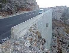
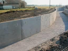
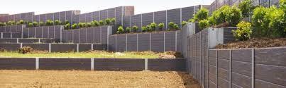
6 APPLICATIONS OF RETAINING WALLS
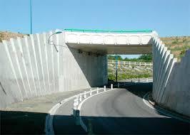
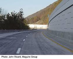
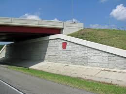
7 APPLICATIONS OF RETAINING WALLS

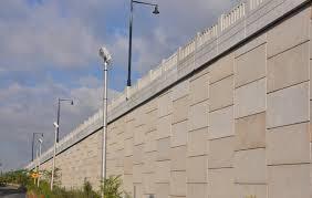
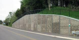
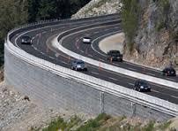
8 APPLICATIONS OF RETAINING WALLS highway

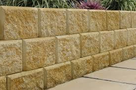
9 GRAVITY RETAINING WALLS o This type of wall has relatively huge size and weight, and not economical for high walls. o They rely on their self weight to support the backfill and achieve stability against failures. o The following are the main types of wall: Masonry gravity walls Concrete gravity walls

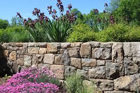
10 MASONRY WALLS

11 SEMIGRAVITY RETAINING WALLS In many cases, a small amount of steel may be used for the construction of gravity walls, thereby minimizing the size of wall sections


12 CANTILEVER RETAINING WALLS Cantilever retaining walls are made of reinforced concrete that consists of a thin stem and a base slab. This type of wall is economical to a height of about 8 m. The cantilever wall utilizes cantilever action to retain the mass behind the wall from assuming a natural slope. Stability of this wall is partially achieved from the weight of soil on the heel portion of the base slab.

13 CANTILEVER WALLS A cantilever wall stem under construction. Made of reinforced concrete that consists of a thin stem and a base slab. This type of wall is economical to a height of about 8 m.

14 COUNTERFORT RETAINING WALLS Counterfort retaining walls are similar to cantilever walls. At regular intervals, however, they have thin vertical concrete slabs known as counterforts that tie the wall and the base slab together. The purpose of the counterforts is to reduce the shear and the bending. The counterfort is behind the wall and subjected to tensile forces.


15 BUTTRESSED RETAINING WALLS A buttressed retaining wall is similar to a counterfort wall, except that the bracing is in the front of the wall and is in compression instead of tension. A cantilever wall stem under construction.


16 SHEET PILE WALLS Steel sheet pile walls are constructed by driving steel sheets into a slope or excavation up to the required depth. Their most common use is within temporary deep excavations. It cannot resist very high pressure.

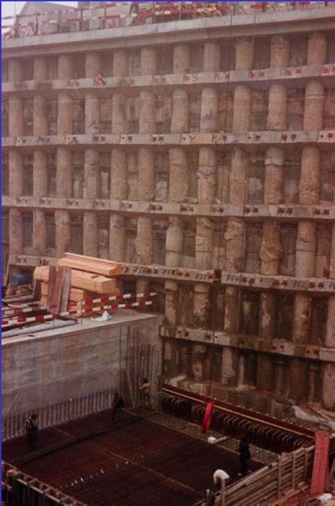
17 PILE WALLS

18 SOIL NAILING
19 PHASES OF DESIGN There are two phases in the design of a conventional retaining wall. I. With the lateral earth pressure known, the structure as a whole is checked for stability. The structure is examined for possible overturning, sliding, bearing capacity, and overall (deep-seated) failures. II. Each component of the structure is checked for strength, and the steel reinforcement of each component is determined. o In this course we will consider the procedures for determining the stability of the retaining wall. Checks for strength can be found in any textbook on reinforced concrete.

20 EXTERNAL AND INTERNAL STABILITY For design of retaining walls we need to consider external and internal stability
21 EXTERNAL STABILITY

22 EXTERNAL STABILITY A retaining wall may fail in any of the following ways: It may overturn about its toe. It may slide along its base. It may fail due to the loss of bearing capacity of the soil supporting the base. It may undergo deep-seated shear failure. It may go through excessive settlement. Bearing Capacity Excessive Settlement


23 EXTERNAL STABILITY Failure by sliding Failure by settlement
24 DEEP SHEAR FAILURE o Deep shear failure can occur along a cylindrical surface, such as abc shown in the figure below, as a result of the existence of a weak layer of soil underneath the wall at a depth of about 1.5 times the width of the base slab of the retaining wall. o In such cases, the critical cylindrical failure surface abc has to be determined by trial and error, using various centers such as O. o The failure surface along which the minimum factor of safety is obtained is the critical surface of sliding.

25 INTERNAL STABILITY

26 INTERNAL STABILITY

27 INTERNAL STABILITY
28 DESIGN OF RETAINING WALLS The Four Primary Concerns for the Design of Nearly any Retaining Wall are: 1. It has an acceptable Factor of Safety with respect to overturning. 2. It has an acceptable Factor of Safety with respect to sliding. 3. The allowable soil bearing pressures are not exceeded. 4. The stresses within the components (stem and footing) are within code allowable limits to adequately resist imposed vertical and lateral loads. It is equally important that it is constructed according to the design.
29 DESIGN OF RETAINING WALLS Phase I Phase II 1. Select trial dimensions 2. Estimate horizontal soil force on stem 3. Check for sliding and overturning 4. Check sub-soil pressures 5. Estimate critical bending and shear 6. Select concrete grade and rebar cover 7. Select rebar, observing minimum requirements This Course Reinforced Concrete Course
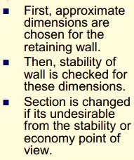
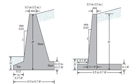
30 Proportioning Retaining Walls Gravity and Cantilever Walls In designing retaining walls, an engineer must assume some of their dimensions. Called proportioning, such assumptions allow the engineer to check trial sections of the walls for stability. If the stability checks yield undesirable results, the sections can be changed and rechecked. Figure shows the general proportions of various retaining-wall components that can be used for initial checks. The top of the stem of any retaining wall should not be less than about 0.3 m for proper placement of concrete. The depth, D, to the bottom of the base slab should be a minimum of 0.6 m. However, the bottom of the base slab should be positioned below the seasonal frost line. For counterfort retaining walls, the general proportion of the stem and the base slab is the same as for cantilever walls. However, the counterfort slabs may be about 0.3 m thick and spaced at center-to-center distances of 0.3H to 0.7H.

31 Proportioning Retaining Walls Gravity wall Cantilever wall
32 Design of Retaining Walls Application of Lateral Earth Pressure Theories to Design Rankine Theory Rankine theory is modified to be suitable for designing a retaining walls. This modification is drawing a vertical line from the lowest-right corner till intersection with the line of backfill, and then considering the force of soil acting on this vertical line. The soil between the wall and vertical line is not considered in the value of P a, so take this soil in consideration as a vertical weight applied on the stem of the retaining wall as will explained later.
33 Design of Retaining Walls The wall is vertical and backfill is horizontal
34 Design of Retaining Walls The wall is vertical and the backfill is inclined with horizontal by angle (α) P a =1/2gH 2 K a H =H+d d=l tanα P a,h =P a cos(α) P a,v =P a sin(α)
with")

35 Design of Retaining Walls The wall is inclined by angle (θ)with vertical and the backfill is inclined with horizontal by angle (α): P a =1/2gH 2 K a
36 Design of Retaining Walls Application of Lateral Earth Pressure Theories to Design Coulomb s Theory Coulomb s theory will remains unchanged (without any modifications). The force P a is applied directly on the wall, so whole soil retained by the wall will be considered in P a the weight of soil will not apply on the heel of the wall.

 P a,v =P a")
37 Design of Retaining Walls P a =1/2gH 2 K a P a,h =P a cos(δ+θ) P a,v =P a sin(δ+θ)


38 where P h = P a cos a P v = P a sin a STABILITY FOR OVERTURNING

39 STABILITY FOR OVERTURNING

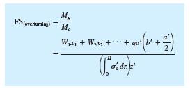
40 STABILITY FOR OVERTURNING Remark Some designers prefer to determine the factor of safety against overturning with the formula
41 EXAMPLE 13.1 OVERTURNING
42 OVERTURNING EXAMPLE 13.2
43 STABILITY FOR SLIDING ALONG THE BASE The horizontal component of active force may causes movement of the wall in horizontal direction (i.e. causes sliding for the wall), this force is called driving force F d =P a,h
44 STABILITY FOR SLIDING ALONG THE BASE The driving force will be resisted by the following forces: 1. Adhesion between the soil (under the base) and the base of retaining wall: c a = adhesion along the base of retaining wall (KN/m) C a = c a B = adhesion force under the base of retaining wall (KN) c a can be calculated from the following relation: c a =K 2 c 2 where c 2 =cohesion of soil under the base So adhesion force is: C a =K 2 c 2 B
45 STABILITY FOR SLIDING ALONG THE BASE 2. Friction force due to the friction between the soil and the base of retaining wall : Friction force is calculated from the following relation: F fr = μ s N where N is the sum of vertical forces calculated in the table of the first check (overturning) N=ΣV (including the vertical component of active force) μ s = coefficient of friction (related to the friction between soil and base) μ s = tan(δ 2 ) δ 2 = K 1 ϕ 2 μ s = tan(k 1 ϕ 2 ) ϕ 2 = friction angle of the soil under the base. F fr = ΣV tan(k 1 ϕ 2 ) Note: K 1 =K 2 =(1/2 2/3) if you are not given them take K 1 =K 2 =2/3
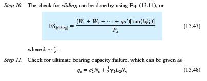
46 STABILITY FOR SLIDING ALONG THE BASE 3. Passive force P P The total resisting force FR can be calculated as following: F R = ΣV tan(k 1 ϕ 2 )+K 2 c 2 B+P P Factor of safety against sliding
47 STABILITY FOR SLIDING ALONG THE BASE Shear strength along the base
48 STABILITY FOR SLIDING ALONG THE BASE If the desired value of FS sliding is not achieved, several alternatives may be investigated: 1. Increase the width of the base slab (i.e., the heel of the footing). 2. Use a key to the base slab. If a key is included, the passive force per unit length of the wall becomes 3. Use a deadman anchor at the stem of the retaining wall. 4. Another possible way to increase the value of F S (sliding) is to consider reducing the value of P a.
49 STABILITY FOR SLIDING ALONG THE BASE 4. Another possible way to increase the value of F S (sliding) is to consider reducing the value of Pa. One possible way to do so is to use the method developed by Elman and Terry (1988) for the case in which the retaining wall has a horizontal granular backfill. The active force, P a, is horizontal (a = 0) so that P a cos a = P h = P a and P a sin a = P v = 0 However, P a = P a(1) + P a(2) The magnitude of P a(2) can be reduced if the heel of the retaining wall is sloped. For this case, P a = P a(1) + AP a(2)
 + AP")
50 STABILITY FOR SLIDING ALONG THE BASE P a = P a(1) + AP a(2)
51 EXAMPLE 13.1 SLIDING

52 EXAMPLE 13.1 Note: For some designs, the depth D in a passive pressure calculation may be taken to be equal to the thickness of the base slab.
53 SLIDING EXAMPLE 13.2


54 EXAMPLE 13.2
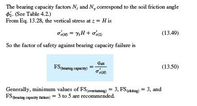
55 STABILITY FOR BEARING CAPACITY FAILURE The net moment of these forces about point C is Let the line of action of the resultant R intersect the base slab at E. Then the distance
56 STABILITY FOR BEARING CAPACITY FAILURE Shape factors F cs, F qs, and F gs = 1 Depth factors : (Use B not B ) Inclination factors

57 EXAMPLE 13.1 Bearing Capacity Failure

58 EXAMPLE 13.1

59 The pressure on the soil at the toe and heel EXAMPLE 13.2
60 SETTLEMENT FAILURE Generally, a factor of safety of 3 is required. The ultimate bearing capacity of shallow foundations occurs at a settlement of about 10% of the foundation width. In the case of retaining walls, the width B is large. Hence, the ultimate load q u will occur at a fairly large foundation settlement. A factor of safety of 3 against bearing capacity failure may not ensure that settlement of the structure will be within the tolerable limit in all cases. Thus, this situation needs further investigation

61 CONSTRUCTION JOINTS Construction joints are vertical and horizontal joints that are placed between two successive pours of concrete. To increase the shear at the joints, keys may be used. If keys are not used, the surface of the first pour is cleaned and roughened before the next pour of concrete.
 that allow the concrete to shrink without noticeable harm. The grooves may be about 6 to 8 mm wide and 12 to 16 mm deep.")
62 CONSTRUCTION JOINTS Contraction joints are vertical joints (grooves) placed in the face of a wall (from the top of the base slab to the top of the wall) that allow the concrete to shrink without noticeable harm. The grooves may be about 6 to 8 mm wide and 12 to 16 mm deep.

63 CONSTRUCTION JOINTS Expansion joints Allow for the expansion of concrete caused by temperature changes; vertical expansion joints from the base to the top of the wall may also be used. These joints may be filled with flexible joint fillers. In most cases, horizontal reinforcing steel bars running across the stem are continuous through all joints. The steel is greased to allow the concrete to expand.

64 DRAINAGE FROM BACKFILL As the result of rainfall or other wet conditions, the backfill material for a retaining wall may become saturated, thereby increasing the pressure on the wall and perhaps creating an unstable condition. For this reason, adequate drainage must be provided by means of 1. Weep holes 2. Perforated drainage pipes
65 DRAINAGE FROM BACKFILL When provided, weep holes should have a minimum diameter of about 0.1 m and be adequately spaced. Note that there is always a possibility that backfill material may be washed into weep holes or drainage pipes and ultimately clog them. Thus, a filter material needs to be placed behind the weep holes or around the drainage pipes, as the case may be; geotextiles now serve that purpose. Two main factors influence the choice of filter material: The grain-size distribution of the materials should be such that (a) The soil to be protected is not washed into the filter and (b) Excessive hydrostatic pressure head is not created in the soil with a lower hydraulic conductivity (in this case, the backfill material). The preceding conditions can be satisfied if the following requirements are met (Terzaghi and Peck, 1967): F : filter B : backfill soil D 15 : diameter through which 15% will pass D 85 : diameter through which 85% will pass

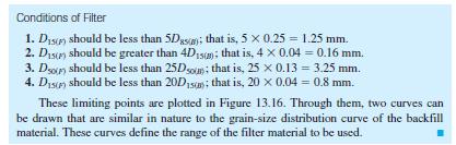
66 DRAINAGE FROM BACKFILL
67 Mechanically Stabilized Retaining Walls More recently, soil reinforcement has been used in the construction and design of foundations, retaining walls, embankment slopes, and other structures. Depending on the type of construction, the reinforcements may be galvanized metal strips, geotextiles, geogrids, or geocomposites. Reinforcement materials such as metallic strips, geotextiles, and geogrids are now being used to reinforce the backfill of retaining walls, which are generally referred to as mechanically stabilized retaining walls.
68 SOIL REINFORCEMENT Reinforced earth is a construction material made from soil that has been strengthened by tensile elements such as metal rods or strips, non biodegradable fabrics (geotextiles), geogrids, and the like. The first reinforced-earth retaining wall with metal strips as reinforcement in the United States was constructed in 1972 in southern California. The beneficial effects of soil reinforcement derive from: (a) the soil s increased tensile strength and (b) the shear resistance developed from the friction at the soil-reinforcement interfaces. Such reinforcement is comparable to that of concrete structures. Currently, most reinforced-earth design is done with free-draining granular soil only. Thus, the effect of pore water development in cohesive soils, which, in turn, reduces the shear strength of the soil, is avoided.
69 Considerations in Soil Reinforcement Metal Strips In most instances, galvanized steel strips are used as reinforcement in soil. However, galvanized steel is subject to corrosion. The rate of corrosion depends on several environmental factors. Binquet and Lee (1975) suggested that the average rate of corrosion of galvanized steel strips varies between and mm/yr. So, in the actual design of reinforcement, allowance must be made for the rate of corrosion. Thus, t c = t design + r (life span of structure) Where t c = actual thickness of reinforcing strips to be used in construction t design = thickness of strips determined from design calculations r = rate of corrosion
70 Considerations in Soil Reinforcement Nonbiodegradable Fabrics Nonbiodegradable fabrics are generally referred to as geotextiles. Geotextiles are not prepared from natural fabrics, because they decay too quickly. Geotextiles may be woven, knitted, or nonwoven. Woven geotextiles are made of two sets of parallel filaments or strands of yarn systematically interlaced to form a planar structure. Knitted geotextiles are formed by interlocking a series of loops of one or more filaments or strands of yarn to form a planar structure. Nonwoven geotextiles are formed from filaments or short fibers arranged in an oriented or random pattern in a planar structure. These filaments or short fibers are arranged into a loose web in the beginning and then are bonded by one or a combination of the following processes: 1. Chemical bonding by glue, rubber, latex, a cellulose derivative 2. Thermal bonding by heat for partial melting of filaments 3. Mechanical bonding by needle punching Needle-punched nonwoven geotextiles are thick and have high in-plane permeability
71 GEOTEXTILES Geotextiles have four primary uses in foundation engineering: 1. Drainage: The fabrics can rapidly channel water from soil to various outlets, thereby providing a higher soil shear strength and hence stability. 2. Filtration: When placed between two soil layers, one coarse grained and the other fine grained, the fabric allows free seepage of water from one layer to the other. However, it protects the fine-grained soil from being washed into the coarsegrained soil. 3. Separation: Geotextiles help keep various soil layers separate after construction and during the projected service period of the structure. For example, in the construction of highways, a clayey subgrade can be kept separate from a granular base course. 4. Reinforcement: The tensile strength of geofabrics increases the load-bearing capacity of the soil.

72 GEOGRIDS Geogrids are high-modulus polymer materials, such as polypropylene and polyethylene, and are prepared by tensile drawing. Geogrids generally are of two types: (a) uniaxial and (b) biaxial. Commercially available geogrids may be categorized by manufacturing process, principally: extruded, woven, and welded. Extruded geogrids are formed using a thick sheet of polyethylene or polypropylene that is punched and drawn to create apertures and to enhance engineering properties of the resulting ribs and nodes. uniaxial Woven geogrids are manufactured by grouping polymeric usually polyester and polypropylene and weaving them into a mesh pattern that is then coated with a polymeric lacquer. Welded geogrids are manufactured by fusing junctions of polymeric strips. Extruded geogrids have shown good performance when compared to other types for pavement reinforcement applications. biaxial

73 GEOGRIDS The commercial geogrids currently available for soil reinforcement have nominal rib thicknesses of about 0.5 to 1.5 mm and junctions of about 2.5 to 5 mm. The grids used for soil reinforcement usually have openings or apertures that are rectangular or elliptical. The dimensions of the apertures vary from about 25 to150 mm. Geogrids are manufactured so that the open areas of the grids are greater than 50% of the total area. They develop reinforcing strength at low strain levels, such as 2% (Carroll, 1988). The major function of geogrids is reinforcement. They are relatively stiff. The apertures are large enough to allow interlocking with surrounding soil or rock to perform the function of reinforcement or segregation (or both).
 More recently, geogrids with triangular apertures have been introduced for construction purposes.")
74 GEOGRIDS Sarsby (1985) investigated the influence of aperture size on the size of soil particles for maximum frictional occurs when B GG > 3.5D 50 where B GG = minimum width of the geogrid aperture D 50 = the particle size through which 50% of the backfill soil passes (i.e., the average particle size) More recently, geogrids with triangular apertures have been introduced for construction purposes. Geogrids with triangular apertures are manufactured from a punched polypropylene sheet, which is then oriented in three substantially equilateral directions so that the resulting ribs shall have a high degree of molecular orientation.

75 General Design Considerations The general design procedure of any mechanically stabilized retaining wall can be divided into two parts: 1. Satisfying internal stability requirements 2. Checking the external stability of the wall The internal stability checks involve determining tension and pullout resistance in the reinforcing elements and ascertaining the integrity of facing elements. The external stability checks include checks for overturning, sliding, and bearing capacity failure.

76 Retaining Walls with Metallic Strip Reinforcement Reinforced-earth walls are flexible walls. Their main components are 1. Backfill, which is granular soil 2. Reinforcing strips, which are thin, wide strips placed at regular intervals, and 3. A cover or skin, on the front face of the wall At any depth, the reinforcing strips or ties are placed with a horizontal spacing of S H center to center; the vertical spacing of the strips or ties is S V center to center. The skin can be constructed with sections of relatively flexible thin material. Lee et al. (1973) showed that, with a conservative design, a 5 mm-thick galvanized steel skin would be enough to hold a wall about 14 to 15 m high. In most cases, precast concrete slabs also can be used as skin. The slabs are grooved to fit into each other so that soil cannot flow out between the joints. When metal skins are used, they are bolted together, and reinforcing strips are placed between the skins.

 under")

77 Retaining Walls with Metallic Strip Reinforcement Reinforced-earth retaining wall (with metallic strip) under construction Metallic strip attachment to the precast concrete slab used as the skin
78 Retaining Walls with Metallic Strip Reinforcement Calculation of Active Horizontal and Vertical Pressure - Rankine method

79 Retaining Walls with Metallic Strip Reinforcement

80 Retaining Walls with Metallic Strip Reinforcement The tie force per unit length of the wall developed at any depth z is Factor of Safety against Tie Failure (2.5 to 3 is recommended)
81 Retaining Walls with Metallic Strip Reinforcement Reinforcing ties at any depth z will fail by pullout if the frictional resistance developed along the surfaces of the ties is less than the force to which the ties are being subjected. The effective length of the ties along which frictional resistance is developed may be conservatively taken as the length that extends beyond the limits of the Rankine active failure zone, which is the zone ABC. Line BC makes an angle of (45 + f 1 /2) with the horizontal. The maximum friction force that can be realized for a tie at depth z is :
82 Retaining Walls with Metallic Strip Reinforcement The factor of safety against tie pullout at any depth z Total Length of Tie
83 Step-by-Step-Design Procedure Using Metallic Strip Reinforcement

84 Step-by-Step-Design Procedure Using Metallic Strip Reinforcement
85 Step-by-Step-Design Procedure Using Metallic Strip Reinforcement

86 EXAMPLE 13.4

87 EXAMPLE 13.4

88 EXAMPLE 13.4

89 EXAMPLE 13.4


90 Retaining Walls with Geotextile Reinforcement Retaining wall with geotextile reinforcement Construction of a geotextilereinforced retaining wall


91 Retaining Walls with Geogrid Reinforcement Geogrid wraparound wall Wall with gabion facing Concrete panel-faced wall
Chapter 13: Retaining Walls
 Chapter 13: Retaining Walls Introduction In general, retaining walls can be divided into two major categories: (a) conventional retaining walls and (b) mechanically stabilized earth walls Conventional
RetainingWalls. Professor of Geotechnical Engineering and Foundations. Faculty of Engineering - Cairo University. By Dr. Ashraf Kamal Hussein
 RetainingWalls By Dr. Ashraf Kamal Hussein Professor of Geotechnical Engineering and Foundations - 2012 1. Introduction Retaining wall: - a structure which retains from failure a soil mass or other materials
Retaining Wall Design
 SIL 211 MEKANIKA TANAH Retaining Wall Design DR. IR. ERIZAL, MAGR DEPARTEMEN TEKNIK SIPIL DAN LINGKUNGAN FAKULTAS TEKNOLOGI PERTANIAN IPB 1 Conventional Retaining Walls Gravity Retaining Structures Stability
DESIGN OF RETAINING WALLS
 DESIGN OF RETAINING WALLS Dr. Izni Syahrizal bin Ibrahim Faculty of Civil Engineering Universiti Teknologi Malaysia Email: iznisyahrizal@utm.my Introduction Retaining wall is used to retain earth or other
Lecture Retaining Wall Week 12
 Lecture Retaining Wall Week 12 Retaining walls which provide lateral support to earth fill embankment or any other form of material which they retain them in vertical position. These walls are also usually
 UNIT V RETAINING WALLS RETAINING WALL 2.5. Retaining walls are structures used to retain earth or water or other materials such as coal, ore, etc; where conditions do not permit the mass to assume its
GEOSYNTHETICS ENGINEERING: IN THEORY AND PRACTICE
 GEOSYNTHETICS ENGINEERING: IN THEORY AND PRACTICE Prof. J. N. Mandal Department of Civil Engineering, IIT Bombay, Powai, Mumbai 400076, India. Tel.022-25767328 email: cejnm@civil.iitb.ac.in Module - 6
CHAPTER 11: WALLS.
 CHAPTER 11: WALLS MODULAR BLOCK WALL (DRY CAST) Rather than being pre-approved as systems, the components of Modular block walls (dry cast) are pre-approved separately. The approved MBW components are
DESIGN AND DETAILING OF RETAINING WALLS
 DESIGN AND DETAILING OF RETAINING WALLS (For class held from nd April 07) Dr. M. C. Nataraja, Professor, Civil Engineering Department, Sri Jayachamarajendra Collge of Engineering, Mysore-5a70 006 Phone:
Geotechnical Analysis of Stepped Gravity Walls
 Geotechnical Analysis of Stepped Gravity Walls Baleshwar Singh 1 * and Birjukumar Mistri 2 1 Associate Professor, Civil Engineering Department, IIT Guwahati, India 2 Former Post-Graduate Student, Civil
DESIGNING AND CONSTRUCTION OF T-WALL RETAINING WALL SYSTEM
 Istanbul Bridge Conference August 11-13, 2014 Istanbul, Turkey DESIGNING AND CONSTRUCTION OF T-WALL RETAINING WALL SYSTEM T. C. NEEL and K.BOZKURT ABSTRACT This work shall consist of the design, manufacture
MAHALAKSHMI ENGINEERING COLLEGE TIRUCHIRAPALLI
 MAHALAKSHMI ENGINEERING COLLEGE TIRUCHIRAPALLI - 621213. QUESTION BANK WITH ANSWER DEPARTMENT: CIVIL SEMESTER: 07 SUBJECT CODE /NAME: CE 2401/DESIGN OF REINFORCED CONCRETE AND BRICK MASONDRY STRUCTURES
SECTION MECHANICALLY STABILIZED EARTH 1.01 SUMMARY
 SECTION 028300 PART 1 GENERAL 1.01 SUMMARY A. Section includes Basis of Design Mechanically Stabilized Earth System: SierraScape Mechanically Stabilized Earth (MSE) retaining wall system having high density
SPECIFICATIONS FOR PRECAST MODULAR BLOCK RETAINING WALL SYSTEM (revised 5/8/7)
") Page 1 of 7 STONE STRONG SYSTEMS SPECIFICATIONS FOR PRECAST MODULAR BLOCK RETAINING WALL SYSTEM (revised 5/8/7) PART 1: GENERAL 1.01 Description A. Work includes furnishing and installing precast modular
Page 1 of 7 STONE STRONG SYSTEMS SPECIFICATIONS FOR PRECAST MODULAR BLOCK RETAINING WALL SYSTEM (revised 5/8/7) PART 1: GENERAL 1.01 Description A. Work includes furnishing and installing precast modular
MagnumStone Specifications Gravity
 MagnumStone Specifications Gravity SPECIFICATION FOR MAGNUMSTONE GRAVITY MECHANICALLY STABILIZED EARTH SYSTEM PART 1: GENERAL.01Description The work consists of supplying and installing all aspects of
Application of Geotextiles in Pavement Drainage Systems
 International Journal of Civil Engineering Research. ISSN 2278-3652 Volume 5, Number 4 (2014), pp. 385-390 Research India Publications http://www.ripublication.com/ijcer.htm Application of Geotextiles
Geoguide 6 The New Guide to Reinforced Fill Structure and Slope Design in Hong Kong
 Geoguide 6 The New Guide to Reinforced Fill Structure and Slope Design in Hong Kong Geotechnical Engineering Office Civil Engineering Department The Government of the Hong Kong Special Administrative Region
SPECIFICATIONS FOR PRECAST MODULAR BLOCK RETAINING WALL SYSTEM (revised 9/17/18)
") Page 1 of 8 STONE STRONG SYSTEMS SPECIFICATIONS FOR PRECAST MODULAR BLOCK RETAINING WALL SYSTEM (revised ) PART 1: GENERAL 1.01 Description A. Work includes furnishing and installing precast modular blocks
Page 1 of 8 STONE STRONG SYSTEMS SPECIFICATIONS FOR PRECAST MODULAR BLOCK RETAINING WALL SYSTEM (revised ) PART 1: GENERAL 1.01 Description A. Work includes furnishing and installing precast modular blocks
Earth Retaining Walls CIVL455 CHAPTER I: INTRODUCTION
 Earth Retaining Walls CIVL455 CHAPTER I: INTRODUCTION Earth retaining structures are designed to overcome significant variation in ground levels to provide either a sloping or flat ground on the retained
Design of Semi gravity Retaining Walls
 Design of Semi gravity Retaining Walls Example 13.1 A semi gravity retaining wall consisting of plain concrete (weight = 145 lb/ft³) is shown in Figure 13.9. The bank of supported earth is assumed to weigh
IMPROVEMENT OF SOIL BEARING CAPACITY USING GEOSYNTHETICS
 IMPROVEMENT OF SOIL BEARING CAPACITY USING GEOSYNTHETICS Revati Kulkarni Civil Engineering, SITS, Narhe ABSTRACT Soil alone is able to carry only compressive and shear forces. However, through the use
NPTEL Course. GROUND IMPROVEMENT Factors affecting the behaviour and performance of reinforced soil
 Lecture 27 NPTEL Course GROUND IMPROVEMENT Factors affecting the behaviour and performance of reinforced soil Prof. G L Sivakumar Babu Department of Civil Engineering Indian Institute of Science Bangalore
SECTION SPECIFICATION FOR MECHANICALLY STABILIZED EARTH TWO STAGE WALL SYSTEM
 SECTION 02830 SPECIFICATION FOR MECHANICALLY STABILIZED EARTH TWO STAGE WALL SYSTEM ## THIS SECTION IS WRITTEN IN CSI 3-PART FORMAT AND IN CSI PAGE FORMAT. NOTES TO THE SPECIFIER, SUCH AS THIS, ARE INDICATED
ICBO Evaluation Service, Inc Workman Mill Road, Whittier, California
 ER-5435 Reissued May 1, 2002 ICBO Evaluation Service, Inc. 5360 Workman Mill Road, Whittier, California 90601 www.icboes.org Filing Category: DESIGN Masonry MESA RETAINING BLOCK WALL SYSTEM TENSAR EARTH
SPECIFICATION FOR MAGNUMSTONE GEOGRID REINFORCED Mechanically Stabilized Earth (MSE) SYSTEM
 SYSTEM") MagnumStone Specifications Geogrid Reinforced SPECIFICATION FOR MAGNUMSTONE GEOGRID REINFORCED Mechanically Stabilized Earth (MSE) SYSTEM PART 1: GENERAL 1.01 Description The work consists of supplying
MagnumStone Specifications Geogrid Reinforced SPECIFICATION FOR MAGNUMSTONE GEOGRID REINFORCED Mechanically Stabilized Earth (MSE) SYSTEM PART 1: GENERAL 1.01 Description The work consists of supplying
STANDARDIZATION IN GEOTECH SECTOR V.K.PATIL
 STANDARDIZATION IN GEOTECH SECTOR V.K.PATIL BOMBAY TEXTILE RESEARCH ASSOCIATION L.B.S.MARG, GHATKOPAR (W),MUMBAI-400086. WEB : btraindia.com e-mail : btra@vsnl.com What are Standards? Standards are published
UNIT-1 RETAINING WALLS
 UNIT-1 RETAINING WALLS PART-A 1. Describe about Retaining wall. 2. Define gravity retaining walls. BT-1 3. Classify the types of retaining walls. 4. Explain cantilever retaining wall? 5. Describe about
This paper describes the salient features of a
 Geogrid Reinforced Soil Walls with Welded Wire Mesh Facing to Retain the Approaches to a Flyover This paper describes the salient features of a project wherein geogrid reinforced soil walls with a welded
Subject Index ASTM D , 28, 57, 63, 67, 83-86, 98, 111, ASTM D , 57
 STP952-EB/JUI. 1987 Subject Index Abrasion resistance, 120, 168-169 Apparent opening size, 7, 21, 29-30, 172-173 defined, 30 versus equivalent opening size, 9-12 Apparent slope height, 96 Approved list,
SECTION MECHANICALLY STABILIZED EARTHEN SLOPES. Display hidden notes to specifier by using Tools / Options / View / Hidden Text.
 PART 1 GENERAL SECTION 02260 MECHANICALLY STABILIZED EARTHEN SLOPES Display hidden notes to specifier by using Tools / Options / View / Hidden Text. 1.1 SECTION INCLUDES A. ** NOTE TO SPECIFIER ** Delete
Downloaded from Downloaded from /1
 PURWANCHAL UNIVERSITY VI SEMESTER FINAL EXAMINATION-2003 LEVEL : B. E. (Civil) SUBJECT: BEG359CI, Foundation Engineering. Full Marks: 80 TIME: 03:00 hrs Pass marks: 32 Candidates are required to give their
Module 4 Reinforced Soil Systems. Introduction To Geosynthetics In Transportation. Prepared by. For the Local Technical Assistance Program.
 Module 4 Reinforced Soil Systems Introduction To Geosynthetics In Transportation Prepared by July 2007 For the Local Technical Assistance Program The Geosynthetic Materials Association (GMA) represents
Chapter 18 EARTH RETAINING STRUCTURES
 Chapter 18 EARTH RETAINING STRUCTURES Final SCDOT GEOTECHNICAL DESIGN MANUAL June 2010 SCDOT Geotechnical Design Manual Earth Retaining Structures Table of Contents Section Page 18.1 Introduction...18-1
twenty six concrete construction: foundation design ELEMENTS OF ARCHITECTURAL STRUCTURES: FORM, BEHAVIOR, AND DESIGN DR. ANNE NICHOLS SPRING 2013
 ELEMENTS OF ARCHITECTURAL STRUCTURES: FORM, BEHAVIOR, AND DESIGN DR. ANNE NICHOLS SPRING 2013 lecture twenty six concrete construction: www.tamu.edu foundation design Foundations 1 Foundation the engineered
ENGINEERING DIRECTIVE
 Number: E-95-001 Date: 2/2/95 ENGINEERING DIRECTIVE Ross B. Dindio (Signature on Original) CHIEF ENGINEER The purpose of this engineering directive is to formally notify ALL Department engineering personnel
Behavior of Geosynthetic-Reinforced Earth
 Behavior of Geosynthetic-Reinforced Earth Presented by Kousik Deb Assistant Professor Department of Civil Engineering IIT Kharagpur Problems for Foundations on Weak Soils Experience excessive settlement
MOA Project # Golden View Drive Intersection & Safety Upgrades
 Appropriate transitions can include extending the insulation beyond the roadway improvements, reducing the insulation thickness, or angling the insulation downward. Use of a frost tolerant section, an
Earth Retaining System
 Hashemite University Department of Civil Engineering Foundation Engineering Dr. Omar Al-Hattamleh Earth Retaining System Earth slopes and earth retaining structures Used to maintain two different ground
MSE WALLS CASE STUDIES. by John G. Delphia, P.E. TxDOT Bridge Division Geotechnical Branch
 MSE WALLS CASE STUDIES by John G. Delphia, P.E. TxDOT Bridge Division Geotechnical Branch COMMON RETAINING WALL TYPES CONCRETE BLOCK MSE TEMPORARY EARTH SPREAD FOOTING Gabions Drilled Shaft Soil Nail Tiedback
twenty seven concrete construction: foundation design Foundation Structural vs. Foundation Design Structural vs. Foundation Design
 ARCHITECTURAL STRUCTURES: FORM, BEHAVIOR, AND DESIGN DR. ANNE NICHOLS SRING 2017 lecture twenty seven Foundation the engineered interface between the earth and the structure it supports that transmits
Wall Modular Block Mechanically Stabilized Earth, Item S.
 Wall Modular Block Mechanically Stabilized Earth, Item 532.0300.S. A Description (1) This special provision describes designing, furnishing materials and erecting a permanent earth retention system in
twenty four foundations and retaining walls Foundation Structural vs. Foundation Design Structural vs. Foundation Design
 ALIED ARCHITECTURAL STRUCTURES: STRUCTURAL ANALYSIS AND SYSTEMS DR. ANNE NICHOLS SRING 2018 lecture twenty four Foundation the engineered interface between the earth and the structure it supports that
CE2401-DESIGN OF REINFORCED CONCRETE AND BRICK MASONRY QUESTION BANK
 CE2401-DESIGN OF REINFORCED CONCRETE AND BRICK MASONRY QUESTION BANK UNIT-1 PART-A 1. What is a Retaining wall? 2. What are the disadvantages of gravity retaining walls? 3. What are the types of retaining
TERRASTOP SYSTEM 2 RETAINING WALLS. Section Page 1 PART 1 - GENERAL 1.1 SUMMARY
 Section 02832 - Page 1 PART 1 - GENERAL 1.1 SUMMARY 1.2 DEFINITIONS 1.3 SUBMITTALS 1.4 JOB MOCK-UP A. This section includes furnishing and installation of modular interlocking concrete masonry units bearing
SPECIFICATION FOR CORNERSTONE GEOGRID REINFORCED SEGMENTAL RETAINING WALL SYSTEM
 CornerStone Specifications Geogrid Reinforced SPECIFICATION FOR CORNERSTONE GEOGRID REINFORCED SEGMENTAL RETAINING WALL SYSTEM PART 1: GENERAL 1.01 Description The work consists of supplying and installing
Stability of a Mechanically Stabilized Earth Wall
 Stability of a Mechanically Stabilized Earth Wall GEO-SLOPE International Ltd. www.geo-slope.com 1400, 633-6th Ave SW, Calgary, AB, Canada T2P 2Y5 Main: +1 403 269 2002 Fax: +1 403 266 4851 Introduction
A. Modular Unit - A concrete wall interlocking element, machine made from portland cement, water and aggregates.
 Section 02832 - Page 1 PART 1 - GENERAL 1.1 SUMMARY 1.2 DEFINITIONS 1.3 SUBMITTALS 1.4 JOB MOCK-UP A. This section includes furnishing and installation of modular interlocking concrete masonry units bearing
T-WALL.
 The T-WALL Retaining Wall System is a gravity structure constructed of individual precast T-WALL units. Each T-WALL unit consists of a front face panel and a stem, which extends back into and engages the
INNOVATIVE EARTH RETAINING SYSTEM ADOPTED AT THE PROPOSED PRINTING COMPLEX PROJECT FOR AITKEN SPENCE (PVT) LTD. AT MAWARAMANDIYA
 LTD. AT MAWARAMANDIYA") INNOVATIVE EARTH RETAINING SYSTEM ADOPTED AT THE PROPOSED PRINTING COMPLEX PROJECT FOR AITKEN SPENCE (PVT) LTD. AT MAWARAMANDIYA Shiromal Fernando (Email: shiromal@csec.lk) Vasana Jayasena Neomal Ferdinando
INNOVATIVE EARTH RETAINING SYSTEM ADOPTED AT THE PROPOSED PRINTING COMPLEX PROJECT FOR AITKEN SPENCE (PVT) LTD. AT MAWARAMANDIYA Shiromal Fernando (Email: shiromal@csec.lk) Vasana Jayasena Neomal Ferdinando
GEOSYNTHETICS ENGINEERING: IN THEORY AND PRACTICE
 GEOSYNTHETICS ENGINEERING: IN THEORY AND PRACTICE Prof. J. N. Mandal Department of civil engineering, IIT Bombay, Powai, Mumbai 400076, India. Tel.022-25767328 email: cejnm@civil.iitb.ac.in Module - 4
Section ( ) SPECIFICATION FOR SEGMENTAL CONCRETE UNIT RETAINING WALL
 SPECIFICATION FOR SEGMENTAL CONCRETE UNIT RETAINING WALL") Section 02834 (32 32 23) SPECIFICATION FOR SEGMENTAL CONCRETE UNIT RETAINING WALL PART 1: GENERAL 1.01 Description A. Work shall consist of furnishing and construction of a County Materials Retaining Wall
Section 02834 (32 32 23) SPECIFICATION FOR SEGMENTAL CONCRETE UNIT RETAINING WALL PART 1: GENERAL 1.01 Description A. Work shall consist of furnishing and construction of a County Materials Retaining Wall
Foundation Design. π = pi ( radians or 180 ) ρ = reinforcement ratio in concrete beam design = A s /bd µ = coefficient of static friction
 ρ = reinforcement ratio in concrete beam design = A s /bd µ = coefficient of static friction") Foundation Design Notation: a = name for width dimension A = name for area b = width of retaining wall stem at base = width resisting shear stress b o = perimeter length for two-way shear in concrete footing
Foundation Design Notation: a = name for width dimension A = name for area b = width of retaining wall stem at base = width resisting shear stress b o = perimeter length for two-way shear in concrete footing
Earthquake Design of Flexible Soil Retaining Structures
 Earthquake Design of Flexible Soil Retaining Structures J.H. Wood John Wood Consulting, Lower Hutt 207 NZSEE Conference ABSTRACT: Many soil retaining wall structures are restrained from outward sliding
Pulaski County, Virginia
 Pulaski County, Virginia Typical Retaining Wall Details Based on the 2009 International Residential Code CONTENTS Timber Retaining Wall... 2 General Requirements... 2 Wall Construction... 2 Deadmen...
PE Exam Review - Geotechnical
 PE Exam Review - Geotechnical Resources and Visual Aids Item Page I. Glossary... 11 II. Parameters... 9 III. Equations....11 IV. Tables, Charts & Diagrams... 14 1. Module 1 - Soil Classification... 14
Modular Course on Foundations and Earth retaining Structures for Building and Infrastructure Projects 9th March 2000
 The Institution of Engineers of Ireland Modular Course on Foundations and Earth retaining Structures for Building and Infrastructure Projects 9th March 2000 MODULE 4 RETAINING STRUCTURES DEEP EXCAVATIONS
Advance Design of RC Structure Retaining Wall
 1 Retaining Wall Retaining Walls What are retaining walls Retaining walls are soil-structure systems intended to support earth backfills. Type of retaining walls Gravity retaining wall gravity walls rely
DIVISION: EXTERIOR IMPROVEMENTS SECTION: RETAINING WALLS SECTION: SEGMENTAL RETAINING WALLS REPORT HOLDER:
 0 Most Widely Accepted and Trusted ICC-ES Evaluation Report ICC-ES 000 (800) 423-6587 (562) 699-0543 www.icc-es.org ESR-1784 Issued 02/2018 This report is subject to renewal 02/2019. DIVISION: 32 00 00
UPRR INDUSTRIAL LEAD BRIDGE T-WALL RETAINING WALL SYSTEM 5.0 x 7.5 UNITS DESIGN UNIT 018 WORK PACKAGE 04
 UPRR INDUSTRIAL LEAD BRIDGE T-WALL RETAINING WALL SYSTEM 5.0 x 7.5 UNITS DESIGN UNIT 018 WORK PACKAGE 04 1. Description This work shall consist of the design, manufacture and construction of a T-WALL structure
T-WALL & STONE STRONG
 shawprecastsolutions.com & STONE STRONG Retaining Walls PRODUCT GUIDE & TECHNICAL REFERENCE MANUAL Providing the right solutions. The Retaining Wall System is a gravity structure constructed of individual
SEPA Environmental Checklist Mercer Island Center for the Arts. Attachment F Geotechnical Supplemental Memo
 SEPA Environmental Checklist Mercer Island Center for the Arts Attachment F Geotechnical Supplemental Memo January 2017 MEMORANDUM DATE: May 6, 2015 TO: FROM: RE: CC: Katie Oman, Mercer Island Center for
Misan University - College of Engineering Civil Engineering Department
 CHAPTER 2 Soil and Excavations Soil investigation including two phases: surface investigation and subsurface investigation Surface investigation involves making a preliminary judgment about the site s
GEOSYTHETIC SLOPE SPEC-V0704rev.doc STANDARD SPECIAL PROVISION FOR GEOSYNTHETIC REINFORCED SLOPE CONSTRUCTION
 GEOSYTHETIC SLOPE SPEC-V0704rev.doc STANDARD SPECIAL PROVISION FOR GEOSYNTHETIC REINFORCED SLOPE CONSTRUCTION I. DESCRIPTION - This work consists of furnishing the required materials and construction of
RETAINING WALL SYSTEM. ViaWall. ViaWall A. ViaWall B. ViaBlock
 RETAINING WALL SYSTEM ViaWall ViaWall A ViaWall B ViaBlock Table of contents Introduction page 1 ViaWall type A Elements of the system 1. Reinforced concrete panel 2. Reinforcing meshes 3. U-bolts Additional
Geo synthetics and Reinforced Soil Structures Prof. K. Rajagopal Department of Civil Engineering Indian Institute of Technology, Madras
 Geo synthetics and Reinforced Soil Structures Prof. K. Rajagopal Department of Civil Engineering Indian Institute of Technology, Madras Lecture - 9 Different Types of Soil Retaining Structures Hello students,
A complex reinforced structure applied at hilly road repair case in Taiwan
 A complex reinforced structure applied at hilly road repair case in Taiwan Introduction In the filed of geotechnical engineering, frequently soil nailing is applied to the application of the shallow-depth
CHAPTER 10: GENERAL STRUCTURAL DETAILS
 CHAPTER 10: GENERAL STRUCTURAL DETAILS 10.1 GENERAL It shall be in accordance with JSCE Standard Specification (Design), 9.1, "steel" shall be taken to signify "steel or CFRM". 10.2 CONCRETE COVER (1)
Pavement reinforcement
 Pavement reinforcement Reducing fatigue cracking 2 Innovative solutions for asphalt and unbound pavements and soft ground stabilisation Whether constructing a gravel forestry track over soft soil or resurfacing
Section ( ) MODULAR CONCRETE RETAINING WALL
 MODULAR CONCRETE RETAINING WALL") Section 02834 (32 32 23) MODULAR CONCRETE RETAINING WALL PART 1: GENERAL 1.01 Description A. Work shall consist of furnishing and construction of a KEYSTONE 133Elite Unit Retaining Wall System or equal
Section 02834 (32 32 23) MODULAR CONCRETE RETAINING WALL PART 1: GENERAL 1.01 Description A. Work shall consist of furnishing and construction of a KEYSTONE 133Elite Unit Retaining Wall System or equal
Earth Retaining Structures and Systems Submittal Checklist. Part One: Materials and Material Properties
 Earth Retaining Structures and Systems Submittal Checklist Part One: Materials and Material Properties Provide a sample of the reinforcement material and material specifications describing the material
Section ( ) KEYSTONE CONCRETE RETAINING WALL
 KEYSTONE CONCRETE RETAINING WALL") Section 02834 (32 32 23) KEYSTONE CONCRETE RETAINING WALL PART 1: GENERAL 1.01 Description A. Work shall consist of designing, furnishing and construction of a KEYSTONE Compac Unit Retaining Wall System
Section 02834 (32 32 23) KEYSTONE CONCRETE RETAINING WALL PART 1: GENERAL 1.01 Description A. Work shall consist of designing, furnishing and construction of a KEYSTONE Compac Unit Retaining Wall System
SPECIFICATION FOR REINFORCED SOIL WALL
 SPECIFICATION FOR REINFORCED SOIL WALL 1.0 EXTENT OF WORK The work shall consist of Reinforced Soil walls built in accordance with this specification and in conformity with the lines, levels and details
CYPRESS Stone Geogrid Reinforced Retaining Wall Installation Specification SECTION CONCRETE SEGMENTAL RETAINING WALL PART 1 GENERAL
 CYPRESS Stone Geogrid Reinforced Retaining Wall Installation Specification SECTION 02832- CONCRETE SEGMENTAL RETAINING WALL PART 1 GENERAL 1.01 Description A) The work covered by this section includes
Brooks/Cole Thomson LearningiM. Fundamentals of Geotechnical Engineering. Braja M. Das. California State University, Sacramento
 Fundamentals of Geotechnical Engineering Braja M. Das California State University, Sacramento Brooks/Cole Thomson LearningiM Australia Canada Mexico Singapore Spain United Kingdom United States CHAPTER
CHAPTER 6 RETAINING AND REINFOCED EARTH WALL WORKS
 CHAPTER 6 RETAINING AND REINFOCED EARTH WALL WORKS 6.1 General Retaining walls are structures, which support and retain earth in order to prevent failure of sediments in the places where stability of slope
CONTENTS. Top-up Course for TCP T3 on GIFW and Building Works with Significant Geotechnical Content. Lecture 5 : Retaining Walls
 Top-up Course for TCP T3 on GIFW and Building Works with Significant Geotechnical Content Lecture 5 : Retaining Walls CONTENTS Common Types of Retaining Walls Design and Construction Considerations Supervision
APPENDIX B ABC STRUCTURES DESIGN GUIDE
 APPENDIX B ABC STRUCTURES DESIGN GUIDE The Cohos Evamy Partners TABLE OF CONTENTS Page No. DISCLAIMER... I 1. STRUCTURAL DESIGN GUIDELINES... 1 2. GENERAL REQUIREMENTS (FIGURE B.2, STEP 1)... 1 3. GENERAL
Soil Mechanics Lateral Earth Pressures page Lateral Earth Pressures in case of inclined ground surface or friction at wall-ground interface
 Soil Mechanics Lateral Earth Pressures page 9 7.6 Lateral Earth Pressures in case of inclined ground surface or friction at wall-ground interface By now, we have considered the wall as perfectly smooth
STANDARD SPECIFICATION FOR CRIBLOCK CONCRETE CRIBWALL
 STANDARD SPECIFICATION FOR CRIBLOCK CONCRETE CRIBWALL 1. SCOPE 2. DESIGN 3. MATERIALS 4. CONSTRUCTION 5. METHOD OF MEASUREMENT AND PAYMENT SCOPE This Specification sets out requirements for the design,
Compressibility of Soil. Chapter 11
 Compressibility of Soil Chapter 11 TOPICS INTRODUCTION ELASTIC SETTLEMENT Stress distribution in soil masses CONSOLIDATION SETTLEMENT Fundamentals of consolidation Calculation of 1-D Consolidation Settlement
Use of Polymer Geogrid Composite to support rail track over weak saturated clay subgrade a case study
 Geo-Environmental Engineering 2015 Concordia University Montreal, Canada May 21-22, 2015 Use of Polymer Geogrid Composite to support rail track over weak saturated clay subgrade a case study Sam Bhat *,
DHANALAKSHMI COLLEGE OF ENGINEERING, CHENNAI DEPARTMENT OF CIVIL ENGINEERING 2 MARK QUESTIONS WITH ANSWERS CE FOUNDATION ENGINEERING UNIT 1
 DHANALAKSHMI COLLEGE OF ENGINEERING, CHENNAI DEPARTMENT OF CIVIL ENGINEERING 2 MARK QUESTIONS WITH ANSWERS CE6502 - FOUNDATION ENGINEERING Subject Code: CE6502 UNIT 1 1. What are the informations obtained
ICC-ES Evaluation Report Issued July 1, 2011 This report is subject to renewal in one year.
 ICC-ES Evaluation Report ESR-1959 Issued July 1, 2011 This report is subject to renewal in one year. www.icc-es.org (800) 423-6587 (562) 699-0543 A Subsidiary of the International Code Council DIVISION:
Upon speaking with the representatives with Technical Foundations as well as Walder Foundations, it was determined that:
 As part of our analyses, we have considered the design and construction of the cantilever retaining wall that will be located along the north side of Lucks Lane, between Falling Creek and Gladstone Glen
BS EN :2004 EN :2004 (E)
") Contents List 1. General 1.1 Scope 1.1.1 Scope of Eurocode 2 1.1.2 Scope of Part 1-1 of Eurocode 2 1.2 Normative references 1.2.1 General reference standards 1.2.2 Other reference standards 1.3 Assumptions
Contents List 1. General 1.1 Scope 1.1.1 Scope of Eurocode 2 1.1.2 Scope of Part 1-1 of Eurocode 2 1.2 Normative references 1.2.1 General reference standards 1.2.2 Other reference standards 1.3 Assumptions
DIVISION: EXTERIOR IMPROVEMENTS SECTION: SEGMENTAL RETAINING WALLS REPORT HOLDER: ANCHOR WALL SYSTEMS EVALUATION SUBJECT:
 0 Most Widely Accepted and Trusted ICC ES Evaluation Report ICC ES 000 (800) 423 6587 (562) 699 0543 www.icc es.org ESR 1959 Reissued 07/2018 This report is subject to renewal 07/2019. DIVISION: 32 00
Ground Improvement Using Steel Reinforcing Strips
 SAICE Geotechnical Division: Seminar on Ground Improvement Johannesburg, South Africa 8 & 9 October, 2001 Ground Improvement Using Steel Reinforcing Strips ACS Smith Reinforced Earth (Pty) Ltd, Johannesburg,
Providing proper drainage system
 Environment Friendly and Cost Effective Alternative to Conventional Graded Filters Providing proper drainage system for structures such as earth retaining structures, pavements, water front structures,
SECTION SEGMENTAL CONCRETE UNIT MASONRY RETAINING WALL MAXIMUM HEIGHT OF 5-0 HIGH
 DIVISION 32 EXTERIOR IMPROVEMENTS SECTION 32 32 23.13 SEGMENTAL CONCRETE UNIT MASONRY RETAINING WALL MAXIMUM HEIGHT OF 5-0 HIGH PART 1: GENERAL 1.01 Scope of Standards A. This standard provides general
GEOSYNTHETICS ENGINEERING: IN THEORY AND PRACTICE
 GEOSYNTHETICS ENGINEERING: IN THEORY AND PRACTICE Prof. J. N. Mandal Department of civil engineering, IIT Bombay, Powai, Mumbai 400076, India. Tel.022-25767328 email: cejnm@civil.iitb.ac.in Module-5 LECTURE-