Structural Design for a Low Rise Office Building
|
|
|
- Kenneth Fitzgerald
- 6 years ago
- Views:
Transcription
1 University of Wyoming Wyoming Scholars Repository Honors Theses AY 15/16 Undergraduate Honors Theses Spring Structural Design for a Low Rise Office Building Shane Halverson University of Wyoming, shalver1@uwyo.edu Follow this and additional works at: Recommended Citation Halverson, Shane, "Structural Design for a Low Rise Office Building" (2016). Honors Theses AY 15/ This Dissertation/Thesis is brought to you for free and open access by the Undergraduate Honors Theses at Wyoming Scholars Repository. It has been accepted for inclusion in Honors Theses AY 15/16 by an authorized administrator of Wyoming Scholars Repository. For more information, please contact scholcom@uwyo.edu.
2 STRUCTURAL DESIGN FOR A LOW RISE OFFICE BUILDING Senior Honors Project Shane Halverson Mentor: Derek Swanson The overall goal of this project was to obtain a thorough understanding of structural system design and construction. This was accomplished by studying the four phases a structural project goes through; schematic design, design development, construction documents, and construction administration. After gaining a thorough understanding of these four phases the knowledge was applied to design an entire structural system for a four story office building located in Cheyenne, WY. This system was designed in accordance to all applicable codes.
3 Table of Contents Introduction..3 Body of Paper...4 Background...4 Research...5 Engineer s Timeline..5 Phases of Typical Building Project...6 Design Process..6 Applying What We Learned.7 Schematic Design.7 Design Development 8 Construction Documents..9 Construction Administration...10 Calculations.11 Conclusion...11 Appendix A..13 Appendix B..18 Appendix C..25 Appendix D..32 Appendix E..35 Page 2
4 STRUCTURAL DESIGN FOR A LOW RISE OFFICE BUILDING Introduction As society advances, the built environment becomes an ever increasing component of everyday life. As a result, buildings and their design are becoming a very scientific field. Buildings can be as simple as four walls and a roof or as complicated as hundred story skyscrapers. Either way there is an art to the design and construction of buildings. Typically, people only see the outside of a building, or the skin. However, there is much more to a building then stone and windows. Buildings can be looked at much like living, breathing human beings. On the outside is a smooth skin, but under that skin are several different systems working together in perfect harmony to make life possible. The mechanical system of a building is like the respiratory system in a body. It is responsible for bringing in fresh air, along with conditioning each space to the right temperature. The electrical system is much like the nervous system in a body. It keeps the lights on and allows the building to function smoothly. The system this project focuses on is the structural system. The structural system of a building is exactly like the skeletal system in a body. The structural system is responsible for making the building stand and stay standing, even in extreme conditions. Page 3
5 STRUCTURAL DESIGN FOR A LOW RISE OFFICE BUILDING Body of Paper The overall goal of this project was to obtain a thorough understanding of structural system design and construction. This was accomplished by studying the four phases a structural project goes through; schematic design, design development, construction documents, and construction administration. After gaining a thorough understanding of these four phases the knowledge was applied to design an entire structural system for a four story office building located in Cheyenne, WY. This system was designed in accordance to all applicable codes. The project is discussed in depth within the background, research, applying what we learned and conclusion sections. Background This project was conducted in conjunction with the University of Wyoming Architectural Engineering Capstone class ARE This class is designed to give students real world experience in a classroom setting. Students are broken into teams of 2 to 3, and each team is required to design the entire structural system for a given building. The building for this year s capstone class was a new student center for the Laramie County Community College campus located in Cheyenne, Wyoming. The building will be used for various purposes and will contain offices, classrooms, and some student services. The capstone class is designed to be students final class prior to graduation. Therefore, students within the class have a good understanding of various structural systems. Students at this stage in their education also have a solid understanding of how buildings function, along with how the various systems within a building interact. The intent of the capstone class is to connect all the individual items students have learned. It is also designed to give students exposure to how an Page 4
6 actual construction project takes place. Students are not required to design an entire building but rather a component of that building as they would if they were working for an engineering firm. The class begins the semester by researching the construction process, where students gain a better understanding of how a project goes from conception to construction. After the initial research component, the class is divided into four phases as a real construction project would be, and each phase had a submittal associated with it. The remainder of this paper will follow the layout of the class. Research This project began with research on the construction process. We looked at how one person s idea becomes a finished project, paying special attention to the structural engineer s role within the overall project scope. Our findings are summarized in the engineer s timeline, phases of typical building project, and design process sections. Engineer s Timeline. Although a building may take a few years to complete, the structural engineer is not involved with the project the entire time. Depending on the complexity of the structural system, and whether it is a focal point or if it is hidden in the background, the structural engineer is only actively involved in about 25-50% of the entire project. Typically, they are subcontracted to the architect and do not come into the project until both the owner and the architect have a good understanding of the overall building design. This means the structural engineer typically has little say in the overall appearance of the project. Once the structural system erection is complete, the structural engineer is mostly done with the project. Occasionally the engineer will receive questions resulting from a design change or a potential issue, but the majority of the engineer s responsibility is complete at this point. Page 5
7 Phases of Typical Building Project. Our research revealed that there are four main phases a typical building project goes through. These phases are as follows: Schematic Design, Design Development, Construction Documents, and Construction Administration. The first three phases are all preconstruction. Only the fourth phase directly deals with the actual construction of the building and specifically the structural system. Each of the first three phases takes the design progressively more towards the final design. The design is done in a progressive manner so that a rough idea of the overall project costs can be estimated as early as possible. Other aspects of the project are continually undergoing revision as well, so it would not make sense to design the entire structural system at once only to have the building design change, which would require the system to be completely redesigned. Design Process. In addition to the four specific project phases described above, there is also a design process that is incorporated. The first step is to choose a structural system. This is perhaps the most important step in the entire process. Building size, use, and desired structural aesthetics are key factors in deciding which type of structural system to utilize. Once a structural system is chosen and the project location is known, the next step is to find all applicable codes. Different regions, states, and municipalities work under different codes. Following the correct codes is crucial for there are legal consequences if every code is not followed exactly as written. The third step is to calculate the loads. Buildings are exposed to two main types of loads, which are gravity and lateral loads. Gravity loads act in the vertical direction and are the result of the weight of the building and its contents. Lateral loads act in the horizontal direction and are the result of wind or seismic factors. During this stage the loads are very roughly calculated as the Page 6
8 actual building material and structural component weights are not yet known. These first three steps are all incorporated into the schematic design. Once a rough idea of the loading is known, member sizing can begin. This is typically contained within the design development phase. The construction document deals with precisely sizing each and every structural member along with all the connections between members. Once all the members are properly sized, the actual construction documents can be created. This is a set of blueprints with all the information required to build and erect the structural system. At this point the design process is complete. However, there is one more phase in the project. For the structural engineer, this phase is known as the construction administration phase. During this portion of the project the engineer is responsible for handling any questions that arise. These questions may be on constructability of the system or how to solve a problem that has arisen in the field. Applying What We Learned The second half of the class project is to actually apply not only what we learned in the initial research, but everything we have learned over our entire scholastic career. We applied the knowledge we have gained to design the entire structural system for the four story building that was previously mentioned. This process was broken into the four design phases previously introduced; schematic design, design development, construction documents, and construction administration, along with a section dedicated to calculations. Schematic Design. For our schematic design submittal, we were required to provide an executive summary of our intended structural system, state applicable building codes, give load & design criteria, and give details on our intended structural system. The first step in accomplishing these tasks was to select an appropriate structural system. There are countless systems that would Page 7
9 work in this situation, including mass timber, concrete, and reinforced masonry. My partner and I chose to use a structural system comprised of steel columns, girders, and beams, working in conjunction with a mixture of concrete shear walls and braced steel frames. This is a very common system for a building of this scale and usage. It is also a very popular system in this part of Wyoming. These two factors contribute to reducing the overall construction costs for the project. The first step was to determine the necessary codes. Since the building is located within the city limits of Cheyenne, the City Council of Cheyenne is the governing body. Therefore, the governing building code is the 2015 version of the International Building Code (IBC). ASCE 7-10 also governs and is closely tied to the IBC. The next step was to establish our load and design criteria. This includes factors such as our Flat Roof Snow Load, which we calculated to be 21 psf, our Basic Wind Speed, which was found to be 115 mph, and our seismic factors, which were found to be Ss = 0.155g and S1 = 0.036g. The seismic factors were found using the United States Geological Services website. The final step of the first phase was to discuss the details of the intended structural system. This included details on the foundation design based on the given geotechnical report, along with typical framing information. The lateral system and the interaction between its two different parts were also discussed. All the details of the schematic design submittal are located in Appendix A, which contains the entire submittal. Design Development. The second required submittal for this project was the design development or DD submittal. As discussed earlier, this submittal builds on where the SD submittal left off. The deliverables were an entire set of plans for the building, including a foundation plan. Also required were detail drawings showing specific areas of the buildings where the interaction between components may not have been entirely clear. The first step in Page 8
10 accomplishing the task for this submittal was to lay out the framing. This was challenging because the building was not square and each level changes slightly. The framing layout was further complicated by the way the architect laid out each floor. The building contains several slanting hallways and other challenging aspects that make column layout difficult. To complete the layout, the structural framing building was drawn in the 3D modeling program Revit. Gridlines were then added to create rectangular spaces that were easily broken into framing bays. Columns were then placed at most of the gridline intersection points. Unfortunately, due to the inconsistency of hallways and rooms from one floor to the next, there are a couple columns that are not continuous from the foundation to the roof. This resulted in the need for a transfer beam, a very deep steel member, to transfer the load from the upper column to the lower columns. Once a justifiable framing plan was created, rough member sizing could be done. In order to accomplish this, the tributary area for each member is calculated and the load acting on that area is found. This gives the total load acting on the member, which can then be used to determine how big the member needs to be in order to successful carry the load. For additional information on the contents of the DD submittal, please see appendix B, which contains the entire DD submittal. Construction Documents. The third phase of this project was creating the construction documents. This package contains everything necessary to fabricate and construct the structural system for this building. The first step in this process was reviewing the feedback from the DD submittal. The feedback implied that some of our detail drawings were not clear enough to be constructed, so that was remedied. Once we had made the necessary changes to existing plans, we moved into completing the new tasks. Page 9
11 The biggest challenge with the CD submittal was presenting all of the necessary information in a clear manner due to the limited amount of space on the plans, and each member needed to be labeled and dimensioned. In order to clearly present all necessary information, plan notes were used as much as possible. Each member was labeled as clearly as possible and specific attention was paid to minimizing the use of leader lines. The CD plans have a much higher level of detail and are very clearly explained, whereas the DD plans gave a good indication of member location but were not completely buildable. For your convenience, the complete CD submittal has been included in Appendix C. Construction Administration. The fourth phase of the project was the Construction Administration phase. On a real project this phase is during the actual construction of the building. During the CA portion of the project the engineer has already completely design all necessary elements for the structural system to be erected. The engineers job during the time the structural system is erected is to solve any problems that arise. Perhaps a coordination issue causes a pipe and a beam to be at the same height. The structural engineer would be responsible for finding a solution. For our CA submittal we were required to solve a theoretical problem. The problem was that one of the shear tabs, the component that connects the girder to the column was installed 1 too low. As a result, the bolt holes did not line up on the girder. Students were required to respond to the Request For Information sent out about the problem with a reasonable solution. The solution my team came up with was welding the shear tab to the girder. A 12 long, 3/16 weld was strong enough to withstand the loading. For corresponding calculations and a detailed drawing solution please the RFI and our solution in Appendix D. Page 10
12 Calculations. The final submittal of our project was the calculations submittal. On a real project the calculations would have needed to be done prior to the construction document phase. Although these calculations are typically never submitted because contractors only need the results, within the scope of the classroom setting submitting calculations was critical. Our calculations package included all of the math required to size the structural components for the building. Both hand calculations along with computer calculations were utilized. All computer calculations were performed in Microsoft Excel. Excel enabled us to make adjustments without having to redo all of our equations, however each formula in excel had to be created and programed by us. Not every member and connection in the entire building was included within our calculations submittal. The submittal includes one of each typical component. This includes one column, beam, girder, connection, interior footing, and column base plate. Also required in the calculations submittal was all the applicable loading condition calculations for factors such as snow, wind and snow. Altogether the calculations package is roughly 27 pages. There are a few discrepancies between the construction documents submittal member sizes and the calculations submittal member sizes. This is due to the calculations not being entirely done when the CD submittal was due. In a real world setting the calculations would have to be completed and then the results are published in the CD submittal. The calculations submittal has included in Appendix E for your convenience. Conclusion Structural design is not an easy process. It is very complicated due to the numerous factors that contribute to the various loads. However, it is a process that can be broken down into a few, very systematic steps. Overall structural design is truly an art; an art which requires both analytical and creative inputs. There are several considerations that go into designing structural Page 11
13 systems. The ultimate goal of the structure is to keep the building standing and preserve life safety. Keeping this goal in mind, the structural system is designed to meet all aesthetic and architectural requirements. An engineer s true job is problem solving. They are responsible for coming up with a solution to the problem the architect and the owner have created. A successful solution will meet all design requirements as well as all code requirements. This project has given students a preview of just how challenging it is to create a viable solution. Page 12
14 APPENDIX A Schematic Design Submittal Page 13

15 LARAMIE COMMUNITY COLLEGE WELCOME CENTER STRUCTURAL SCHEMATIC DESIGN CAPSTONE ARE 4720 GROUP 7 Josh Knutson Shane Halverson Page 14
16 Structural System Narrative 1. Executive Summary A. The primary gravity structure for the LCCC Welcome Center Project will be a combination of structural steel columns, beams, and joists. Lateral loads will be supported using braced steel frames. The roof structure will consist of metal deck roof diaphragm supported by open web steel joists. The floor structure will consist of composite floor deck supported by steel beams. Roof joists and floor beams will bear on steel beams supported by steel columns. It is anticipated the building will be founded on a conventional spread footing and stem wall foundation system. 2. Building Code A. The governing building code for the project will be 2015 IBC. The fundamental design criteria are anticipated to be as follows: 1) 2015 International Building Code 2) ASCE Loading & Design Criteria A. Roof Snow Loads: 1) Design Roof Snow Load = 21 psf 2) Flat Roof Snow Load = 21 psf 3) Snow Exposure Factor (Ce) = 1.0 4) Importance Factor (I) = 1.0 5) Thermal Factor (Ct) = 1.0 6) Ground Snow Load (Pg) = 30 psf 7) Rain on Snow Surcharge = 0 psf 8) Sloped Roof Factor (Cs) = 1.00 B. Wind Design Data 1) Basic Wind Speed = 115 mph 2) Mean Roof Height = ± 60 ft 3) Risk Category = II 4) Exposure Category = C 5) Enclosure Classification = Enclosed building 6) Internal Pressure Coeff. = ) Directionality (Kd) = ) Topographical Factor (Kzt) = 1 C. Earthquake Design Data 1) Risk Category = II 2) Importance Factor (I) = 1.0 3) Mapped Spectral Response Accelerations: a) Ss = 0.155g b) S1 = 0.054g 4) Site Class = B 5) Spectral Response Coef.: a) Sds = 0.103g b) Sd1 = 0.036g 6) Seismic Design Category = A 7) Basic Structural System = Building Frame Systems Page 15
17 8) Seismic Resisting System = Steel braced frames not specifically detailed for seismic resistance 9) Design Base Shear V = Cs*W 10) Seismic Response Coef. (Cs) = ) Response Mod. Factor (R) = 3 12) Analysis Procedure = Equivalent Lateral Force Analysis D. Design Loads: 1) Dead Load = weight of structure + 10psf lighting, ceiling, mech. & plumb. 2) Live Load at Elevated Floors = 80 psf 3) Mechanical Loads = weight of equipment, but not less than 125 psf 4. New Structure A. The proposed structural systems described below are a representation of group 7 s initial analysis and design. B. Structural Systems for Proposed Welcome Center. C. Foundation: 1) Based on the Geotechnical Report, the following is anticipated for this project. a) The foundation will be constructed of conventional continuous strip footings (supporting walls) and individual shallow spread footings (supporting columns or other isolated loads) placed on over-excavated and re-compacted subgrade, or engineered aggregate piers per the Geotechnical Report. 1) Assumed allowable bearing pressure of 3,000 psf. 2) Strip footings will be a minimum of 18 w x 12 t with 36 d exterior stem walls (total of 48 deep). 3) Spread footings will be a minimum of 24 square. Size and reinforcing will vary by location in an effort to balance footing pressures and minimize differential settlement. 4) Bottom of exterior foundation walls + footings shall have a minimum depth of 42 below finish exterior grade for requirements for frost protection. Interior footings within heated areas of the building may be placed at a minimum of 12 below finished grade. D. Lateral System: 1) Steel braced frames will provide the lateral resistance. The lateral resisting members will be positioned to minimize the architectural impact and/or enhance the architectural features. 2) Load bearing reinforced masonry walls will provide lateral resistance where possible. Specific locations and design parameters will be developed to provide as many dual use structural systems as possible. 3) In all locations, the metal roof and floor decks will be used as horizontal diaphragms to distribute the lateral loads to the bracing and interior or exterior shear walls. E. Roof Framing 1) The typical roof, covering the majority of the building, shall be constructed of open-web steel joist framing as follows: a) 24 to 30 deep standard open web steel joists bearing on a steel beam and column structure. b) Wide flange steel beams are estimated to be 16 to 24 deep. c) 1 ½ Type B metal roof deck (assume 20 gage). Page 16
18 d) The deck will be used as a diaphragm for lateral load transfer to the bracing and/or shear walls. e) Acoustical deck F. Floor Framing 1) The typical floor shall be constructed of composite slab-steel deck floor system. a) 1.5 VLI to 3 VLI composite steel deck. b) 4 to 7 normal weight concrete slab. G. Wall Framing 1) The typical exterior wall construction will be either masonry or cold formed metal studs with sheathing. The exposed finishes are expected to be a masonry veneer or metal panel. Unsupported Stud Height Metal Stud Wall Information Wall Finish Stud Size, Gage, and Spacing 18 Metal panel, gypsum, or stucco Masonry veneer (CMU, stone, brick, etc.) 16 Metal panel, gypsum, or stucco Masonry veneer (CMU, stone, brick, etc.) Metal panel, gypsum, or stucco Masonry veneer (CMU, stone, brick, etc.) 16 2) The interior walls will be primarily metal studs and drywall, that may be reinforced with sheathing or strapping to resist lateral loads as needed. H. Slab-on-grade: 1) 4 normal weight 3500 psi reinforced concrete. Page 17
19 APPENDIX B Design Development Submittal Page 18
20 LEGEND NOTES LEGEND NOTES ARE COMMON TO ALL SOME NOTES MAY NOT APPLY TO THIS SHEET Project Status 24' - 4" 23' - 10" 25' - 6" 24' - 6" 7' - 8" 21' - 11" 3' - 9" 24' - 8" 17' - 6" 18' - 6" 21' - 4" 18' - 4" 1' - 5" 1' - 4" A B C D E H G 33' - 11" 10' - 7" 30' - 6" 3' - 5" 6' - 3" 14' - 8" 1' - 8" 3' - 0" TYP. UNO 1' - 0" TYP. 4 S.6 1' - 0" 2' - 7" 3' - 10" 13' - 10" 16' - 3" 4' - 10" 1' - 0" 3' - 0" 10' - 9" 35' - 0" 1' - 0" 1' - 0" 9' - 1" 1' - 7" 0' - 8" 1' - 0" 0' - 8" 0' - 8" 1' - 0" 2' - 9" 1' - 7" 1' - 4" 1' - 7" 20' - 5" 3' - 2" 1' - 9" 1' - 7" 1' - 7" 1' - 4" 1' - 7" 1' - 4" 1' - 7" 10' - 4" 1' - 10" 1' - 8" 2' - 0" 5' - 0" Typ. Spread Footing 5' x 5' x 1' Thick Typ. Perimeter Spread Footing Extends from Foundation wall 2' Typ. Spread Footing 5' x 5' x 1' Thick 27' - 4" 1' - 7" 13' - 9" 1' - 0" TYP. 3' - 0" TYP. 5' - 6" 1' - 6" 2' - 8" 6' - 2" 2' - 0" 11' - 6" 1' - 7" 14' - 4" FOUNDATION PLAN S.1 Project Number Issue Date LARAMIE COUNTY COMMUNITY COLLEGE Revisions WELCOME CENTER 1 FOUNDATION PLAN 1/8" = 1'-0" \\studentfiles.uwyo.edu\storage$\desktop\are 4720\Revit Project\Structural Central Group 7_jknutso4.rvt 3/31/2016 5:12:59 PM BENJAMIN TALPOS NOTES: 1. SLAB-ON-GRADE: 1A. TOP OF SLAB-ON-GRADE ELEVATION=100'-0" UNLESS NOTED OTHERWISE 1B. TYPICAL SLAB-ON-GRADE IS 4" THICK WITH #4 REINF. AT 18" O.C., E.W. 1C. FOR EXTENTS OF SLAB-ON-GRADE DEPRESSIONS, SLOPES, STEPS, OPENINGS, SEE ARCH DRAWINGS 2. STEM WALLS: 2A. TOP OF STEM WALL = 100'-0" UNLESS NOTED OTHERWISE 2B. BOTTOM OF STEM WALL = TOP OF FOOTING 3. FOOTINGS: 3A. TOP OF INTERIOR FOOTINGS = 99'-0" UNLESS NOTED OTHERWISE 3B. TOP OF EXTERIOR FOOTINGS = 96'-6" 3C. CENTER SPREAD FOOTINGS ON COLUMNS UNLESS DIMENSIONED OTHERWISE 3D. CENTER STRIP FOOTINGS UNDER STEM WALLS UNLESS DIMENSIONED OTHERWISE 3E. TOP OF INTERIOR PILASTERS = 100'-0" UNLESS NOTED OTHERWISE 3F. TOP OF EXTERIOR PILASTERS = 100'-0" UNLESS NOTED OTHERWISE 4. COLUMNS 4A. ALL COLUMNS ARE TO BE CENTERED ON GRIDLINES UNLESS DIMENSIONED OTHERWISE PAPPAS & PAPPAS ARCHITECTS, PC Architecture Engineering Planning Interiors, DLR Group inc., a Wyoming corporation, ALL RIGHTS RESERVED Page 19
21 33' - 11" A B C D E H G ' - 4" 23' - 10" 25' - 6" 24' - 6" 7' - 8" 21' - 11" 3' - 9" 3' - 6" 21' - 2" 17' - 6" 18' - 6" 21' - 4" 2' - 2" 16' - 2" 1' - 7" 3' - 4" 6' - 0" 24' - 8" 36' - 0" 21' - 4" LEGEND NOTES LEGEND NOTES ARE COMMON TO ALL SOME NOTES MAY NOT APPLY TO THIS SHEET Revisions 33' - 11" 10' - 7" 30' - 6" 3' - 5" 6' - 3" 14' - 8" 4' - 4" BENJAMIN TALPOS Architecture Engineering Planning Interiors, DLR Group inc., a Wyoming corporation, ALL RIGHTS RESERVED PAPPAS & PAPPAS ARCHITECTS, PC \\studentfiles.uwyo.edu\storage$\desktop\are 4720\Revit Project\Structural Central Group 7_jknutso4.rvt 3/31/2016 5:12:59 PM S.2 2ND LEVEL FLOOR FRAMING PLAN Project Number Issue Date LARAMIE COUNTY COMMUNITY COLLEGE WELCOME CENTER Project Status Diagonal Bracing 1 2ND LEVEL FRAMING PLAN 1/8" = 1'-0" NOTES: 1. COLUMNS: 1A. ALL COLUMNS ARE TO BE CENTERED ON GRIDLINES UNLESS DIMENSIONED OTHERWISE 2. BEAMS AND JOISTS: 2A. BEAMS AND JOISTS ARE TO BE EQUALLY SPACED BETWEEN GRID LINES OR ALONG GIRDERS UNLESS DIMENSIONED OTHERWISE 2B. DIMENSIONS ARE TO CENTERLINE OF MEMBERS UNLESS NOTED OTHERWISE 3. SLAB-ON-DECK 3A. 2ND LEVEL TOP OF SLAB-ON-DECK ELEVATION = 116'-0" Diagonal Bracing Diagonal Bracing Diagonal Bracing Page 20
22 A B C D E H G ' - 4" 23' - 10" 25' - 6" 24' - 6" 7' - 8" 21' - 11" 7' - 3" 21' - 2" 17' - 6" 18' - 6" 21' - 4" 2' - 2" 16' - 2" LEGEND NOTES LEGEND NOTES ARE COMMON TO ALL SOME NOTES MAY NOT APPLY TO THIS SHEET Revisions 33' - 11" 10' - 7" 30' - 6" 3' - 5" 6' - 3" 14' - 8" BENJAMIN TALPOS Architecture Engineering Planning Interiors, DLR Group inc., a Wyoming corporation, ALL RIGHTS RESERVED PAPPAS & PAPPAS ARCHITECTS, PC \\studentfiles.uwyo.edu\storage$\desktop\are 4720\Revit Project\Structural Central Group 7_jknutso4.rvt 3/31/2016 5:12:59 PM S.3 3RD LEVEL FLOOR FRAMING PLAN Project Number Issue Date LARAMIE COUNTY COMMUNITY COLLEGE WELCOME CENTER Project Status Diagonal Bracing 1 3RD LEVEL FRAMING PLAN 1/8" = 1'-0" NOTES: 1. COLUMNS: 1A. ALL COLUMNS ARE TO BE CENTERED ON GRIDLINES UNLESS DIMENSIONED OTHERWISE 2. BEAMS AND JOISTS: 2A. BEAMS AND JOISTS ARE TO BE EQUALLY SPACED BETWEEN GRID LINES OR ALONG GIRDERS UNLESS DIMENSIONED OTHERWISE 2B. DIMENSIONS ARE TO CENTERLINE OF MEMBERS UNLESS NOTED OTHERWISE 3. SLAB-ON-DECK 3A. 3RD LEVEL TOP OF SLAB-ON-DECK ELEVATION = 130'-0" Diagonal Bracing Diagonal Bracing Diagonal Bracing Page 21
23 D E H G ' - 11" 10' - 7" 30' - 6" A B C 24' - 4" 23' - 10" 25' - 6" 24' - 6" 7' - 8" 29' - 7" 21' - 11" 3' - 9" 7' - 3" 3' - 6" 21' - 2" 17' - 6" 18' - 6" 21' - 4" 2' - 2" 16' - 2" LEGEND NOTES LEGEND NOTES ARE COMMON TO ALL SOME NOTES MAY NOT APPLY TO THIS SHEET Revisions 3' - 5" 6' - 3" 14' - 8" BENJAMIN TALPOS Architecture Engineering Planning Interiors, DLR Group inc., a Wyoming corporation, ALL RIGHTS RESERVED PAPPAS & PAPPAS ARCHITECTS, PC \\studentfiles.uwyo.edu\storage$\desktop\are 4720\Revit Project\Structural Central Group 7_jknutso4.rvt 3/31/2016 5:13:00 PM S.4 4TH LEVEL FLOOR FRAMING PLAN Project Number Issue Date LARAMIE COUNTY COMMUNITY COLLEGE WELCOME CENTER Project Status Diagonal Bracing 1 4TH LEVEL FRAMING PLAN 1/8" = 1'-0" NOTES: 1. COLUMNS: 1A. ALL COLUMNS ARE TO BE CENTERED ON GRIDLINES UNLESS DIMENSIONED OTHERWISE 2. BEAMS AND JOISTS: 2A. BEAMS AND JOISTS ARE TO BE EQUALLY SPACED BETWEEN GRID LINES OR ALONG GIRDERS UNLESS DIMENSIONED OTHERWISE 2B. DIMENSIONS ARE TO CENTERLINE OF MEMBERS UNLESS NOTED OTHERWISE 3. SLAB-ON-DECK 3A. 4TH LEVEL TOP OF SLAB-ON-DECK ELEVATION = 144'-0" Diagonal Bracing Diagonal Bracing Diagonal Bracing Page 22
24 A B C D E H G ' - 4" 23' - 10" 25' - 6" 24' - 6" 36' - 10" 21' - 2" 17' - 6" 18' - 6" 21' - 4" 18' - 4" LEGEND NOTES LEGEND NOTES ARE COMMON TO ALL SOME NOTES MAY NOT APPLY TO THIS SHEET Revisions 33' - 11" 10' - 7" 30' - 6" 3' - 5" 6' - 3" 14' - 8" BENJAMIN TALPOS Architecture Engineering Planning Interiors, DLR Group inc., a Wyoming corporation, ALL RIGHTS RESERVED PAPPAS & PAPPAS ARCHITECTS, PC \\studentfiles.uwyo.edu\storage$\desktop\are 4720\Revit Project\Structural Central Group 7_jknutso4.rvt 3/31/2016 5:13:00 PM S.5 ROOF FRAMING PLAN Project Number Issue Date LARAMIE COUNTY COMMUNITY COLLEGE WELCOME CENTER Project Status 1 ROOF FRAMING PLAN 1/8" = 1'-0" NOTES: 1. COLUMNS: 1A. ALL COLUMNS ARE TO BE CENTERED ON GRIDLINES UNLESS DIMENSIONED OTHERWISE 2. BEAMS AND JOISTS: 2A. BEAMS AND JOISTS ARE TO BE EQUALLY SPACED BETWEEN GRID LINES OR ALONG GIRDERS UNLESS DIMENSIONED OTHERWISE 2B. DIMENSIONS ARE TO CENTERLINE OF MEMBERS UNLESS NOTED OTHERWISE 3. SLAB-ON-DECK 3A. ROOF TOP OF SLAB-ON-DECK ELEVATION = 158'-0" Page 23


25 LEGEND NOTES LEGEND NOTES ARE COMMON TO ALL SOME NOTES MAY NOT APPLY TO THIS SHEET Diagonal HSS Frame Bracing Project Status Concrete Shear Walls 1 2 3D for Lateral Systems 2" Metal Deck with 4" Cover W14 x 30 TYP. STEEL DECK DETAIL 1 1/2" = 1'-0" 0' - 4" 0' - 2" 6" LATERAL SYSTEM NOTES: 1. OVERVIEW: 1A.THE LATERAL FORCE RESISTING SYSTEM IS COMPRISED OF TWO MAIN COMPONENTS: BRACED STEEL FRAMES AND CONCRETE SHEAR WALLS. 2. BRACED FRAMES: 2A. THE BRACED FRAMES WILL BE CREATED THROUGH THE UTILIZATION OF DIAGONAL HSS MEMBERS. 2B. BRACE LOCATIONS ARE DISTRIBUTED THROUGHOUT THE BUILDING. EACH WALL HAS ONE CONTINOUS BRACED FRAME. LOCATIONS ARE NOTED ON EACH PLAN. 3. SHEAR WALLS 3A. SHEAR WALLS ARE CONSTRUCTED AROUND THE TWO MAIN STAIRWELLS ALONG WITH THE ELEVATOR SHAFT. 3B. SHEAR WALLS WILL BE CONSTRUCTED FROM 12" THICK CONCRETE ADEQUATELY REINFORCED WITH REBAR. 4" CONCRETE ON 6" GRAVEL BASE #4 BARS AT 18" O.C. EACH WAY LATERAL SYSTEM AND STRUCTURAL DETAILS S.6 Project Number Issue Date LARAMIE COUNTY COMMUNITY COLLEGE Revisions WELCOME CENTER Typ 8" x 2" 20g Metal Stud 36" 6" Floor Slab \\studentfiles.uwyo.edu\storage$\desktop\are 4720\Revit Project\Structural Central Group 7_jknutso4.rvt 3/31/2016 5:13:04 PM BENJAMIN TALPOS 3 METAL STUD DETAIL 1 1/2" = 1'-0" Angle Bracket Bolted to Edge Girder 4 12" FOUNDATION WALL SECTION 1 1/2" = 1'-0" 3"CLR 24" #4 BARS AT 18" O.C. BEND INTO FOOTING LEGS ALTERNATE SIDES (2) #4 BARS CONTINUOUS PAPPAS & PAPPAS ARCHITECTS, PC Architecture Engineering Planning Interiors, DLR Group inc., a Wyoming corporation, ALL RIGHTS RESERVED Page 24
26 APPENDIX C Construction Documents Submittal Page 25
27 LEGEND NOTES LEGEND NOTES ARE COMMON TO ALL SOME NOTES MAY NOT APPLY TO THIS SHEET GROUP 7 24' - 4" 23' - 10" 25' - 6" 24' - 6" 7' - 8" 21' - 11" 3' - 9" 24' - 8" 17' - 6" 18' - 6" 21' - 4" 18' - 4" 1' - 5" 1' - 4" A 2' - 9" 3' - 2" 1' - 9" 1' - 10" 1' - 8" B C D E H G 33' - 11" 10' - 7" 30' - 6" 3' - 5" 6' - 3" 14' - 8" 3' - 10" 12' - 3" 4' - 10" 2' - 0" TYP. UNO 13' - 10" 4' - 0" 1' - 0" TYP. 4 S.6 4' - 0" 1' - 8" 1' - 0" F5x5 F6x6 1' - 0" 4' - 0" 9' - 1" 4' - 0" 10' - 9" 3' - 0" 1' - 0" 1' - 0" 0' - 8" 1' - 7" 1' - 0" 0' - 8" 0' - 8" F10x10 4' - 0" 4' - 0" 2' - 7" 5' - 10" 26' - 7" 4' - 0" 1' - 0" 1' - 7" 1' - 4" 1' - 7" 20' - 5" 1' - 7" F2x2 1' - 7" F10x10 F5x5 F6x6 1' - 4" F10x10 1' - 7" 1' - 7" F2x2 1' - 4" 10' - 4" F10x10 F5x5 F10x10 F10x10 F10x10 F10x10 F10x10 F10x10 F4x4 F4x4 F10x10 F10x10 F10x10 F10x10 F10x10 F10x10 F4x4 F5x5 F5x5 F10x10 F10x10 F10x10 F10x10 F5x5 F10x10 F10x10 F10x10 F10x10 F10x10 5' - 0" 27' - 4" 5' - 0" F6x6 4' - 0" 1' - 7" F10x10 F10x10 F6x6 1' - 0" TYP. 11' - 9" 4' - 0" 5' - 6" 1' - 6" F6x6 2' - 8" 6' - 2" 2' - 0" 11' - 6" 14' - 4" 1' - 7" F10x10 S.1 FOUNDATION PLAN Project Number Issue Date LARAMIE COUNTY COMMUNITY COLLEGE Revisions WELCOME CENTER 1 FOUNDATION PLAN 1/8" = 1'-0" \\studentfiles.uwyo.edu\storage$\desktop\are 4720\Revit Project\Structural Central Group 7_jknutso4.rvt 5/5/2016 2:39:17 PM BENJAMIN TALPOS NOTES: 1. SLAB-ON-GRADE: 1A. TOP OF SLAB-ON-GRADE ELEVATION=100'-0" U.N.O. 1B. TYPICAL SLAB-ON-GRADE IS 4" THICK WITH #4 REINF. AT 18" O.C., E.W. 1C. FOR EXTENTS OF SLAB-ON-GRADE DEPRESSIONS, SLOPES, STEPS, OPENINGS, SEE ARCH DRAWINGS 2. FOUNDATION WALLS: 2A. TOP OF FOUNDATION WALL (T.O.W.) = 100'-0" TYP U.N.O. 2B. BOTTOM OF FOUNDATION WALL = TOP OF FOOTING 2C. TOP OF PILASTERS (T.O.C.) = 99'-4" TYP U.N.O. 3. FOOTINGS: 3A. TOP OF INTERIOR FOOTINGS = 99'-4" TYP U.N.O. 3B. TOP OF EXTERIOR FOOTINGS = 97'-0" TYP U.N.O. 3C. CENTER SPREAD FOOTINGS ON COLUMNS UNLESS DIMENSIONED OTHERWISE 3D. CENTER STRIP FOOTINGS UNDER STEM WALLS UNLESS DIMENSIONED OTHERWISE 4. COLUMNS 4A. ALL COLUMNS ARE TO BE CENTERED ON GRIDLINES UNLESS DIMENSIONED OTHERWISE PAPPAS & PAPPAS ARCHITECTS, PC Architecture Engineering Planning Interiors, DLR Group inc., a Wyoming corporation, ALL RIGHTS RESERVED Page 26
28 33' - 11" A B C D E H G ' - 4" 23' - 10" 25' - 6" 24' - 6" 7' - 8" 21' - 11" 3' - 9" 3' - 6" 21' - 2" 17' - 6" 18' - 6" 21' - 4" 2' - 2" 16' - 2" 1' - 7" 3' - 4" 6' - 0" 24' - 8" 36' - 0" 21' - 4" 33' - 11" 10' - 7" 30' - 6" 3' - 5" 6' - 3" 14' - 8" 4' - 4" W18X106 W18X106 W18X106 W18X106 Diagonal Bracing HSS6X6X1/2 Diagonal Bracing HSS6X6X1/2 Architecture Engineering Planning Interiors, DLR Group inc., a Wyoming corporation, ALL RIGHTS RESERVED Diagonal Bracing HSS6X6X1/2 3' - 6 1/8" 4' - 2 3/8" HSS6X6X1/2 Diagonal Bracing LEGEND NOTES LEGEND NOTES ARE COMMON TO ALL SOME NOTES MAY NOT APPLY TO THIS SHEET PAPPAS & PAPPAS ARCHITECTS, PC Revisions \\studentfiles.uwyo.edu\storage$\desktop\are 4720\Revit Project\Structural Central Group 7_jknutso4.rvt 5/5/2016 2:39:18 PM BENJAMIN TALPOS S.2 Project Number 2ND LEVEL FLOOR FRAMING PLAN Issue Date LARAMIE COUNTY COMMUNITY COLLEGE WELCOME CENTER GROUP 7 1 2ND LEVEL FRAMING PLAN 1/8" = 1'-0" NOTES: 1. COLUMNS: 1A. ALL COLUMNS ARE TO BE CENTERED ON GRIDLINES UNLESS DIMENSIONED OTHERWISE 2. BEAMS AND JOISTS: 2A. BEAMS AND JOISTS ARE TO BE EQUALLY SPACED BETWEEN GRID LINES OR ALONG GIRDERS UNLESS DIMENSIONED OTHERWISE 2B. DIMENSIONS ARE TO CENTERLINE OF MEMBERS UNLESS NOTED OTHERWISE 3. SLAB-ON-DECK 3A. 2ND LEVEL TOP OF SLAB-ON-DECK ELEVATION = 16'-0" 3B. ALL FLOOR SLABS TO UTILIZE 2VLI20 COMPOSITE DECKS WITH 4" OF COVER UNLESS OTHERWISE NOTED Page 27
29 A B C D E H G ' - 4" 23' - 10" 25' - 6" 24' - 6" 7' - 8" 21' - 11" 7' - 3" 21' - 2" 17' - 6" 18' - 6" 21' - 4" 2' - 2" 16' - 2" W10X49 33' - 11" 10' - 7" 30' - 6" 3' - 5" 6' - 3" 14' - 8" Diagonal Bracing HSS6X6X1/2 116' 129' 130' 143' - 0" 6" Diagonal Bracing HSS6X6X1/2 Diagonal Bracing HSS6X6X1/2 Architecture Engineering Planning Interiors, DLR Group inc., a Wyoming corporation, ALL RIGHTS RESERVED HSS6X6X1/2 Diagonal Bracing 2' - 6 1/8" LEGEND NOTES LEGEND NOTES ARE COMMON TO ALL SOME NOTES MAY NOT APPLY TO THIS SHEET PAPPAS & PAPPAS ARCHITECTS, PC Revisions \\studentfiles.uwyo.edu\storage$\desktop\are 4720\Revit Project\Structural Central Group 7_jknutso4.rvt 5/5/2016 2:39:19 PM BENJAMIN TALPOS S.3 Project Number 3RD LEVEL FLOOR FRAMING PLAN Issue Date LARAMIE COUNTY COMMUNITY COLLEGE WELCOME CENTER GROUP 7 1 3RD LEVEL FRAMING PLAN 1/8" = 1'-0" NOTES: 1. COLUMNS: 1A. ALL COLUMNS ARE TO BE CENTERED ON GRIDLINES UNLESS DIMENSIONED OTHERWISE 2. BEAMS AND JOISTS: 2A. BEAMS AND JOISTS ARE TO BE EQUALLY SPACED BETWEEN GRID LINES OR ALONG GIRDERS UNLESS DIMENSIONED OTHERWISE 2B. DIMENSIONS ARE TO CENTERLINE OF MEMBERS UNLESS NOTED OTHERWISE 3. SLAB-ON-DECK 3A. 3RD LEVEL TOP OF SLAB-ON-DECK ELEVATION = 30'-0" 3B. ALL FLOOR SLABS TO UTILIZE 2VLI20 COMPOSITE DECKS WITH 4" OF COVER UNLESS OTHERWISE NOTED Page 28
30 D E H G ' - 11" 10' - 7" 30' - 6" A B C 24' - 4" 23' - 10" 25' - 6" 24' - 6" 7' - 8" 29' - 7" 21' - 11" 3' - 9" 7' - 3" 3' - 6" 21' - 2" 17' - 6" 18' - 6" 21' - 4" 2' - 2" 16' - 2" Diagonal Bracing HSS6X6X1/2 3' - 5" 6' - 3" 14' - 8" Diagonal Bracing HSS6X6X1/2 Diagonal Bracing HSS6X6X1/2 7' - 2 7/8" 7' - 2 7/8" W18X106 Diagonal Bracing HSS6X6X1/2 4' - 2 1/8" Architecture Engineering Planning Interiors, DLR Group inc., a Wyoming corporation, ALL RIGHTS RESERVED 3' - 4" LEGEND NOTES LEGEND NOTES ARE COMMON TO ALL SOME NOTES MAY NOT APPLY TO THIS SHEET PAPPAS & PAPPAS ARCHITECTS, PC Revisions \\studentfiles.uwyo.edu\storage$\desktop\are 4720\Revit Project\Structural Central Group 7_jknutso4.rvt 5/5/2016 2:39:19 PM BENJAMIN TALPOS S.4 Project Number 4TH LEVEL FLOOR FRAMING PLAN Issue Date LARAMIE COUNTY COMMUNITY COLLEGE WELCOME CENTER GROUP 7 1 4TH LEVEL FRAMING PLAN 1/8" = 1'-0" NOTES: 1. COLUMNS: 1A. ALL COLUMNS ARE TO BE CENTERED ON GRIDLINES UNLESS DIMENSIONED OTHERWISE 2. BEAMS AND JOISTS: 2A. BEAMS AND JOISTS ARE TO BE EQUALLY SPACED BETWEEN GRID LINES OR ALONG GIRDERS UNLESS DIMENSIONED OTHERWISE 2B. DIMENSIONS ARE TO CENTERLINE OF MEMBERS UNLESS NOTED OTHERWISE 3. SLAB-ON-DECK 3A. 4TH LEVEL TOP OF SLAB-ON-DECK ELEVATION = 44'-0" 3B. ALL FLOOR SLABS TO UTILIZE 2VLI20 COMPOSITE DECKS WITH 4" OF COVER UNLESS OTHERWISE NOTED Page 29
31 A B C D E H G ' - 4" 23' - 10" 25' - 6" 24' - 6" 29' - 7" 7' - 3" 21' - 2" 17' - 6" 18' - 6" 21' - 4" 18' - 4" L6X6X5/16 L6X6X5/16 W8X10 W8X10 W8X10 W16X26 W16X26 W16X26 W16X26 W16X26 W16X26 W16X26 W16X26 W16X26 W16X26 33' - 11" 10' - 7" 30' - 6" 3' - 5" 6' - 3" 14' - 8" W16X26 W16X26 W16X26 W16X26 W8X10 W8X10 W8X10 W8X10 W8X10 W8X10 12' - 3 1/4" W8X10 W8X10 W8X10 W21X44 W8X10 W8X10 W8X10 W18X106 W21X44 W8X10 W8X10 W8X10 W8X10 W8X10 W8X10 W8X10 12' - 0 1/4" ' - 2" L6X6X5/16 L6X6X5/16 3' - 9 7/8" W16X26 W21X44 17' - 4 1/4" 4' - 1" H ' - 0" A 12K1 12K1 12K1 12K1 12K1 11' - 10" Architecture Engineering Planning Interiors, DLR Group inc., a Wyoming corporation, ALL RIGHTS RESERVED B C D 21' - 8 3/4" HSS4X4X1/4 LEGEND NOTES LEGEND NOTES ARE COMMON TO ALL SOME NOTES MAY NOT APPLY TO THIS SHEET PAPPAS & PAPPAS ARCHITECTS, PC Revisions \\studentfiles.uwyo.edu\storage$\desktop\are 4720\Revit Project\Structural Central Group 7_jknutso4.rvt 5/5/2016 2:39:20 PM BENJAMIN TALPOS S.5 Project Number ROOF FRAMING PLAN Issue Date LARAMIE COUNTY COMMUNITY COLLEGE WELCOME CENTER GROUP 7 1 ROOF FRAMING PLAN 1/8" = 1'-0" NOTES: 1. COLUMNS: 1A. ALL COLUMNS ARE TO BE CENTERED ON GRIDLINES UNLESS DIMENSIONED OTHERWISE 2. BEAMS AND JOISTS: 2A. BEAMS AND JOISTS ARE TO BE EQUALLY SPACED BETWEEN GRID LINES OR ALONG GIRDERS UNLESS DIMENSIONED OTHERWISE 2B. DIMENSIONS ARE TO CENTERLINE OF MEMBERS UNLESS NOTED OTHERWISE 3. SLAB-ON-DECK 3A. ROOF TOP OF SLAB-ON-DECK ELEVATION = 58'-0" 3B. ALL FLOOR SLABS TO UTILIZE 2VLI20 COMPOSITE DECKS WITH 4" OF COVER UNLESS OTHERWISE NOTED 2 HIGH ROOF FRAMING PLAN 1/8" = 1'-0" 3 HIGH ROOF FRAMING PLAN B 1/8" = 1'-0" Page 30


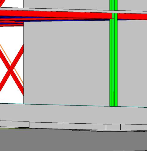


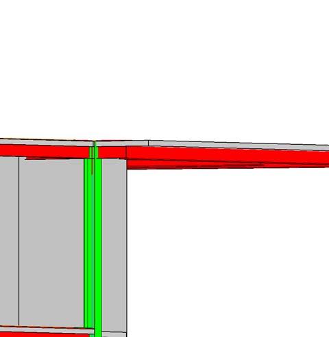
32 LEGEND NOTES GROUP 7 LEGEND NOTES ARE COMMON TO ALL SOME NOTES MAY NOT APPLY TO THIS SHEET Diagonal HSS Frame Bracing 3D for Lateral Systems LATERAL SYSTEM NOTES: 1. OVERVIEW: 1A.THE LATERAL FORCE RESISTING SYSTEM IS COMPRISED OF TWO MAIN COMPONENTS: BRACED STEEL FRAMES AND CONCRETE SHEAR WALLS. 2. BRACED FRAMES: 2A. THE BRACED FRAMES WILL BE CREATED THROUGH THE UTILIZATION OF DIAGONAL HSS MEMBERS. 2B. BRACE LOCATIONS ARE DISTRIBUTED THROUGHOUT THE BUILDING. EACH WALL HAS ONE CONTINOUS BRACED FRAME. LOCATIONS ARE NOTED ON EACH PLAN. 3. SHEAR WALLS 3A. SHEAR WALLS ARE CONSTRUCTED AROUND THE TWO MAIN STAIRWELLS ALONG WITH THE ELEVATOR SHAFT. 3B. SHEAR WALLS WILL BE CONSTRUCTED FROM 12" THICK CONCRETE ADEQUATELY REINFORCED WITH REBAR. 0' - 2" 0' - 4" 2" Metal Deck with 4" Cover W14 x 30 TYP. STEEL DECK DETAIL 1 1/2" = 1'-0" 4" CONCRETE ON 6" GRAVEL BASE Revisions Project Number Issue Date S.6 0' - 8" 2 LARAMIE COUNTY COMMUNITY COLLEGE WELCOME CENTER 1 LATERAL SYSTEM AND STRUCTURAL DETAILS Concrete Shear Walls (3) #4 BARS CONT, EQ SPA Typ 6" x 2" 20g Metal Stud 2' - 0" METAL STUD DETAIL 1 1/2" = 1'-0" 4 FOUNDATION WALL SECTION 1 1/2" = 1'-0" BENJAMIN TALPOS 3, DLR Group inc., a Wyoming corporation, ALL RIGHTS RESERVED 3" CLR 1' - 0" (3) #4 BARS CONTINUOUS Architecture Engineering Planning Interiors Angle Bracket Bolted to Edge Girder 5/5/2016 2:39:27 PM \\studentfiles.uwyo.edu\storage$\desktop\are 4720\Revit Project\Structural Central Group 7_jknutso4.rvt #4 BARS AT 18" O.C. BEND INTO FOOTING ALTERNATE SIDES PAPPAS & PAPPAS ARCHITECTS, PC 6" Floor Slab Page 31
33 APPENDIX D Construction Administration Submittal Page 32
34 Request For Information (RFI) 001 Subject: Structural Steel Project: LCCC Student Services To: ARE 4720 Design Team From: Bob the Builder Date requested by: May 13, :00 p.m. Request: A single shear tab connection with (4) bolts on a W18x35 beam was installed 1 too low. The required capacity is Ru= 45 kips. Please provide field fix for connection. You can provide a verbal or drawing response. Verbal responses shall include enough information that it is contructable. Answer: In response to RFI 001 we have come up with the following solution. Please raise the beam to the original specified installed height then field weld the beam to the shear tab. No bolts are required. A single 12 long, 3/16 fillet weld down the long side of the shear tab will provide a connection of adequate strength. Please see attached drawing and calculations for more detail along with capacity verification. If you have any questions or concerns regarding this solution please do not hesitate to contact me. Page 33
35 Page 34
36 APPENDIX E Structural Calculations Package Page 35

37 Laramie County Community College Welcome Center Structural Calculation Package ARE 4720 STRUCTURAL SYSTEMS DESIGN GROUP 7 SHANE HALVESON & JOSH KNUTSON University of Wyoming Laramie, WY May 11, 2016 Page 36
38 TABLE OF CONTENTS 1 General Site Information Design Criteria Vertical (Gravity Loads) Dead Loads Live Loads Snow Loads..5 3 Lateral Loads Wind Loads Seismic Loads..8 4 Gravity System Design Composite Beam Design Composite Girder Design Open Web Steel Joist Design Column Design Column Base Plate Design Interior Column Footing Design Beam to Girder Connection.25 2 of 27 Page 37


39 1. GENERAL INFORMATION 1.1 Design Criteria 3 of 27 Page 38

40 2. VERTICAL (GRAVITY LOADS) 2.1 Dead Loads 4 of 27 Page 39


41 2.2 Live Loads 2.3 Snow Loads 5 of 27 Page 40

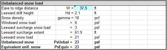
42 6 of 27 Page 41


43 3. LATERAL LOADS 3.1 Wind Loads 7 of 27 Page 42


44 3.2 Seismic Loads 8 of 27 Page 43
45 9 of 27 Page 44
46 10 of 27 Page 45
47 11 of 27 Page 46
48 12 of 27 Page 47
49 13 of 27 Page 48
50 14 of 27 Page 49
51 15 of 27 Page 50
52 4. GRAVITY SYSTEM DESIGN 4.1 Composite Beam Design 16 of 27 Page 51

53 17 of 27 Page 52
54 4.2 Composite Girder Design 18 of 27 Page 53
55 19 of 27 Page 54
56 4.3 Open Web Steel Joist Design 20 of 27 Page 55
57 21 of 27 Page 56

58 4.4 Column Design 22 of 27 Page 57

59 4.5 Column Base Plate Design 23 of 27 Page 58
60 4.6 Interior Column Footing Design 24 of 27 Page 59


61 4.7 Beam to Girder Connection 25 of 27 Page 60
62 26 of 27 Page 61
63 27 of 27 Page 62
The Structural Design of Laramie County Community College Student Services Center
 University of Wyoming Wyoming Scholars Repository Honors Theses AY 15/16 Undergraduate Honors Theses Spring 2016 The Structural Design of Laramie County Community College Student Services Center Katie
Temecula Medical Center Temecula, CA
 Temecula Medical Center Temecula, CA Technical Assignment #2 Sean F. Beville The Pennsylvania State University Architectural Engineering Structural Option Senior Thesis Project Student Advisor: Thomas
Rutgers University Law School Building Addition and Renovation Camden, NJ
 Building Addition and Renovation Camden, NJ Technical Assignment 1 October 5, 2007 Nathan E. Reynolds Structural Option Senior Thesis The Pennsylvania State University Faculty Consultant: Professor M.
Boyds Bear Country Pigeon Forge, TN
 Technical Report 1 Structural Concepts / Structural Existing Conditions Report Executive Summary:, located in Pigeon Forge, Tennessee, is designed as a multifunctional space and tourist attraction for
Danielle Shetler - Structural option Courtyard by Marriott Lancaster, PA
 Structural Analysis Overview: During the structural analysis of the in Lancaster, Pa, a redesign of the lateral and gravity system from masonry bearing and shear walls to a staggered truss system was performed.
Structural Redesign Gravity System
 Redesign Gravity System Design Considerations A composite floor system was used for this design to maximize the efficiency of the material being used. This type of system requires less material and provides
The Structural Redesign of Boyds Bear Country and its Related Systems. Boyds Bear Country, Pigeon Forge, Tennessee
 The Structural Redesign of Boyds Bear Country and its Related Systems Included in this Presentation: Background and Existing System Proposal Problem / Solution Structural System Redesigns Pre-cast Concrete
OVERALL STRUCTURAL SYSTEM
 EXECUTIVE SUMMARY The at the Pittsburgh International Airport, PA, is a 275,000 square foot multi-use building located directly adjacent to the airport s landside terminal. The building consists of an
MOUNTAIN STATE BLUE CROSS BLUE SHIELD HEADQUARTERS
 MOUNTAIN STATE BLUE CROSS BLUE SHIELD HEADQUARTERS PARKERSBURG, WEST VIRGINIA DOMINIC MANNO STRUCTURAL OPTION FACULTY CONSULTANT: DR. ANDRES LEPAGE Technical Report 3 11-21-08 TABLE OF CONTENTS TABLE OF
Jackson Crossing Located in Alexandria, VA. Technical Report 1 Michael Bologna
 Jackson Crossing Located in Alexandria, VA Technical Report 1 Michael Bologna Structural Option Advisor: Dr. Linda Hanagan September 11, 2015 Table of Contents Executive Summary.3 Introduction 4 Purpose..4
Thesis Proposal Structural Redesign / Cost, Schedule and Coordination Analysis / Architectural Impact
 Thesis Proposal Structural Redesign / Cost, Schedule and Coordination Analysis / Architectural Impact Executive Summary:, located in Pigeon Forge, Tennessee, is designed as a multifunctional space and
Structural Technical Report 1 Structural Concepts / Structural Existing Conditions Report
 Michael A. Troxell Structural Option Advisor: Professor Parfitt College of Business Administration Oct. 5, 2005 Structural Technical Report 1 Structural Concepts / Structural Existing Conditions Report
North Shore at Canton Baltimore, MD Beau Menard Technical Report 1
 North Shore at Canton Baltimore, MD Beau Menard Technical Report 1 Structural Schneider 10/05/05 Structural Concepts Executive Summary North Shore at Canton is a 4 story town home and parking garage structure
The designer shall also submit additional information required by the University as described and underlined below.
 I. Structural Engineering Submissions The designer shall submit all information required by the State Construction Office (SCO) as described in the State Construction Manual Chapter 300 - Project Design
Structural System. Design Criteria Fire Resistance Concrete designed for 2 HR rating (worst case) Geotechnical Report Allowable Bearing Capacity
 Geotechnical Report Allowable Bearing Capacity") System Codes and Criteria Design Codes and Standards The design code used is the Wisconsin Administrative Code along with the State of Wisconsin Department of Commerce-Safety & Buildings Chapters Comm
System Codes and Criteria Design Codes and Standards The design code used is the Wisconsin Administrative Code along with the State of Wisconsin Department of Commerce-Safety & Buildings Chapters Comm
CORPORATE HEADQUARTERS
 TECHNICAL REPORT 1 `` CORPORATE HEADQUARTERS Great Lakes Region, U.S.A. M. JULIA HAVERTY STRUCTURAL OPTION ADVISOR: H. SUSTERSIC 12 SEPTEMBER 2014 Contents Executive Summary... 2 Purpose and Scope... 3
Visteon Village Corporate Center
 Visteon Village Corporate Center Van Buren Township, MI Technical Assignment #1 Jamison Morse Structural Option Advisor: Dr. Andres Lapage Jamison Morse Structural Option Visteon Village Center Advisor:
Technical Report 1. Seneca Allegany Casino Hotel Addition. Salamanca, NY
 Technical Report 1 Seneca Allegany Casino Hotel Addition Salamanca, NY Nicholas Reed Structural Option Advisor: Prof. Parfitt Executive Summary The purpose of this technical report was to analyze the existing
Addendum 1 Resort Lifestyle Communities- Office Addition
 Addendum Resort Lifestyle Communities- Office Addition. See attached Reflected Ceiling Plan for framing and drywalling of interior bulkheads and ceilings. See attached Structural Sheets S. and S3.6 for
Technical Report #2. Matthew R Peyton
 Technical Report #2 This Document is Technical Report #2 for 5th year senior thesis in the Architectural Engineering Departments at The Pennsylvania State University. This Report is to prepare a study
Structural Technical Report 1 Structural Concepts / Existing Conditions
 Chris Shelow Structural Advisor: M. Kevin Parfitt Koshland Integrated Natural Science Center 10/05/05 AE 481W Structural Technical Report 1 Structural Concepts / Existing Conditions Executive Summary The
Table of Contents 2. Structural Systems.4 Foundations.4 Floor System...4 Columns..5 Lateral System...5
 WISCONSIN PLACE RESIDENTIAL TECHNICAL ASSIGNMENT 1 OCTOBER 5, 2007 KURT KRASAVAGE THE PENNSYLVANIA STATE UNIVERSITY STRUCTURAL OPTION FACULTY ADVISOR: DR. ALI MEMARI Table of Contents Table of Contents
OF THREE NEW BUILDINGS BEING CONSTRUCTED TO REPLACE THE EXISTING COMPLEX. THE FLOOR SYSTEM OF GEORGE READ HALL IS A HAMBRO COMPOSITE SYSTEM
 EXECUTIVE SUMMARY: GEORGE READ HALL IS A FIVE STORY DORMITORY ON THE UNIVERSITY OF DELAWARE S CAMPUS. EMCOMPASSING 129,000 SQUARE FEET, IT IS THE LARGEST OF THREE NEW BUILDINGS BEING CONSTRUCTED TO REPLACE
Table of Contents.2. Introduction...3 Gravity Loading and Deflections..4. Existing Structural System..8
 WISCONSIN PLACE RESIDENTIAL TECHNICAL ASSIGNMENT 2 OCTOBER 29, 2007 KURT KRASAVAGE THE PENNSYLVANIA STATE UNIVERSITY STRUCTURAL OPTION FACULTY ADVISOR: DR. ALI MEMARI 1 Table of Contents Table of Contents.2
Global Village Rochester Institute of Technology Rochester, New York
 Presentation Outline Welcome Introduction Architecture Existing Structure Problem Statement Arch. Breadth Structural Depth Conclusion Questions Global Village Rochester Institute of Technology Rochester,
Xyston Inn. NY. Proposal. Xiaodong Jiang. Structure Option. Advisor: Dr. Linda Hanagan
 Proposal Xiaodong Jiang Structure Option Advisor: Dr. Linda Hanagan December 12, 2014 Executive Summary Xyston Inn is a 17-story hotel building that will be located in Brooklyn, New York. The design of
Xyston Inn. NY. Proposal. Xiaodong Jiang. Structure Option. Advisor: Dr. Linda Hanagan
 Proposal Xiaodong Jiang Structure Option Advisor: Dr. Linda Hanagan December 12, 2014 Executive Summary Xyston Inn is a 17-story hotel building that will be located in Brooklyn, New York. The design of
Point Pleasant Apartments Point Pleasant, NJ Ryan P. Flynn Structural Option Faculty Consultant: Dr. Hanagan
 Point Pleasant Apartments Point Pleasant, NJ Ryan P. Flynn Structural Option Faculty Technical Report #3: Lateral System Analysis and Confirmation Design Table of Contents Introduction... 3 Executive Summary...
THESIS PROPOSAL. Aubert Ndjolba Structural Option PENN COLLEGE OF TECHNOLOGY. Faculty advisor: Dr. Boothby. Date: 12/09/11
 THESIS PROPOSAL Aubert Ndjolba Structural Option PENN COLLEGE OF TECHNOLOGY Faculty advisor: Dr. Boothby Date: 12/09/11 Table of Contents: Executive Summary.3 Building Introduction.....4 Existing System
1000 CONTINENTAL SQUARE
 1000 CONTINENTAL SQUARE KING OF PRUSSIA, PENNSYLVANIA Carter Davis Hayes Structural Option January 13, 2008 Advisor: Dr. Hanagan TABLE OF CONTENTS TABLE OF CONTENTS... 2 EXECUTIVE SUMMARY... 3 I. STRUCTURAL
TECHNICAL REPORT 1. Structural Concepts / Structural Existing Conditions. Penn State Hershey Medical Center Children s Hospital. Hershey, Pennsylvania
 TECHNICAL REPORT 1 Structural Concepts / Structural Existing Conditions Penn State Hershey Medical Center Children s Hospital Matthew V Vandersall The Pennsylvania State University Architectural Engineering
Technical Report #1. Indiana Regional Medical Center Indiana, PA. Cody A. Scheller. Structural Concepts & Existing Conditions Report
 Technical Report #1 Technical Report #1 Structural Concepts & Existing Conditions Report Indiana Regional Medical Center Cody A. Scheller The Pennsylvania State University Architectural Engineering Faculty
Best Buy Corporate Building D (4) Richfield, MN
 Richfield, MN") Best Buy Corporate Building D (4) Thesis Proposal Professor Boothby December 12 th, 2008 Executive Summary: The Best Buy Corporate Building D is a 6 story building with a total area of 304,610 square feet.
Best Buy Corporate Building D (4) Thesis Proposal Professor Boothby December 12 th, 2008 Executive Summary: The Best Buy Corporate Building D is a 6 story building with a total area of 304,610 square feet.
HIGH RISE CONDO SOHO, NEW YORK, NY
 HIGH RISE CONDO SOHO, NEW YORK, NY TECHNICAL ASSIGNMENT 1 October 5, 2006 Joseph The Pennsylvania State University Structural Option Faculty Advisor: Andres Lepage TABLE OF CONTENTS TABLE OF CONTENTS 2
CORPORATE HEADQUARTERS
 TECHNICAL REPORT 1 REVISIONS `` Image Courtesy RTKL CORPORATE HEADQUARTERS Great Lakes Region, U.S.A. M. JULIA HAVERTY STRUCTURAL OPTION ADVISOR: H. SUSTERSIC 12 DECEMBER 2014 Contents Executive Summary...
Dead Loads (psf): Concrete Floor Slab on Metal Deck 45 psf Mechanical and Ceiling 7 psf Miscellaneous 5 psf Exterior Wall 80 psf
: Concrete Floor Slab on Metal Deck 45 psf Mechanical and Ceiling 7 psf Miscellaneous 5 psf Exterior Wall 80 psf") CODES AND REQUIREMENTS The structural design of Northbrook Corporate Center was based on the International Building Code 2003, which incorporates many of the provisions of ASCE 7. The lateral load design
CODES AND REQUIREMENTS The structural design of Northbrook Corporate Center was based on the International Building Code 2003, which incorporates many of the provisions of ASCE 7. The lateral load design
Project. San Jose City College Physical Education Building. Prepared For. Prepared By PLACE IMAGE HERE. Ken Bauer, AIA Principal
 Project San Jose City College Physical Education Building PLACE IMAGE HERE Prepared For Ken Bauer, AIA Principal LPAS 2484 Natomas Park Drive Sacramento, CA 95833 916.443.0335 Prepared By Steve Ratchye,
School of Engineering and Applied Science Building Miami University, Oxford, OH Technical Assignment 3 December 3, 2007
 School of Engineering and Applied Science Building Miami University, Oxford, OH Technical Assignment 3 December 3, 2007 Jonathan Kirk AE 481W Senior Thesis The Pennsylvania State University Faculty Advisor:
ROOME & GUARRACINO, LLC Consulting Structural Engineers 48 Grove Street Somerville, MA Tel: Fax:
 ROOME & GUARRACINO, LLC Consulting Structural Engineers 48 Grove Street Somerville, MA 02144 Tel: 617.628.1700 Fax: 617.628.1711 March 3, 2016 Mr. Jeff Hoover, Principal Tappe Architects, 6 Edgerly Place
Thesis Proposal. Matthew R Peyton
 This Document is for 5th year senior thesis in the Architectural Engineering Departments at The Pennsylvania State University. S t r u c t u r a l O p t i o n P r o f e s s o r B e h r H o s p i t a l
THESIS PROPOSAL. Aubert Ndjolba Structural Option PENN COLLEGE OF TECHNOLOGY. Faculty advisor: Dr. Boothby. Date: 01/13/12
 THESIS PROPOSAL Aubert Ndjolba Structural Option PENN COLLEGE OF TECHNOLOGY Faculty advisor: Dr. Boothby Date: 01/13/12 Table of Contents: Executive Summary.3 Building Introduction.....4 Existing System
[TECHNICAL REPORT 3] Lateral System Analysis
![[TECHNICAL REPORT 3] Lateral System Analysis](/thumbs/96/126531717.jpg "[TECHNICAL REPORT 3] Lateral System Analysis") Science Center Research Park 3711 Market St. The Pennsylvania State University Department of Architectural Engineering Senior Thesis 2009-2010 Prepared by: November 30, 2009 [TECHNICAL REPORT 3] Lateral
Science Center Research Park 3711 Market St. The Pennsylvania State University Department of Architectural Engineering Senior Thesis 2009-2010 Prepared by: November 30, 2009 [TECHNICAL REPORT 3] Lateral
Thesis Proposal. CHRIS VANDELOGT Structural Option
 Thesis Proposal CHRIS VANDELOGT Global Village Rochester Institute of Technology The Pennsylvania State University Faculty Advisor: Dr. Hanagan 12/12/2011 Executive Summary identifies a problem with the
Thesis Proposal. Office Building. Sayre, PA. Faculty Advisor: Dr. Thomas E. Boothby Revised: April 1, 2013
 Faculty Advisor: Dr. Thomas E. Boothby Revised: April 1, 2013 Office Building Sayre, PA Seth M. Moyer Structural Table of Contents Executive Summary 3 Building Introduction 4 Structural Overview..6 Foundations
Technical Report #1. Matthew R Peyton
 Technical Report #1 This Document is Technical Report #1 for 5th year senior thesis in the Architectural Engineering Departments at The Pennsylvania State University. This Report will include structural
Thesis Proposal. Office Building. Sayre, PA. Faculty Advisor: Dr. Thomas E. Boothby Revised: January 9, 2013
 Faculty Advisor: Dr. Thomas E. Boothby Revised: January 9, 2013 Office Building Sayre, PA Seth M. Moyer Structural Table of Contents Executive Summary 3 Building Introduction 4 Structural Overview..6 Foundations
Structural Technical Report I October 5, 2006 Structural Concepts / Structural Existing Conditions Report
 1 THE ODYSSEY ARLINGTON, VA Aaron Snyder Structural Option Advisor: M. Kevin Parfitt, PE Structural Technical Report I October 5, 2006 Structural Concepts / Structural Existing Conditions Report Executive
William W. Wilkins Professional Building Columbus, Ohio
 William W. Wilkins Professional Building Columbus, Ohio Technical Assignment 1 October 5, 2006 Michelle Structural Option AE 481W Senior Thesis Faculty Advisor: Dr. Boothby Table of Contents Executive
Letter of Transmittal
 Letter of Transmittal November 17, 2014 Ali Said Structural Thesis Advisor The Pennsylvania State University aus59@psu.edu Dear Doctor Said, The following technical report fulfills the fourth Technical
PROJECT: 4/30/14 DATE: REVISIONS: 6/10/14 7/28/14 11/3/14 11/12/14 11/14/14 OF 6
 4/30/14 C 7/31/2014 4'-6" RAMP TO EXISTING GRADE DRAWN: JW 11/12/2014 AS REQ'D 7'-10 1/2" 7'-10 1/2" 7'-10 1/2" 7'-10 1/2" 2'-0 1/2" 4'-10 1/2" 6" 3'-10" 3'-8" L2X2X1/8 @ 16" OC (TYP) L2X2X1/8 @ 16"
Erie on the Park. Timothy Moore Penn State University Architectural Engineering Structural Emphasis Advisor: Prof. Ali Memari
 Timothy Moore Penn State University Architectural Engineering Structural Emphasis Advisor: Prof. Ali Memari Thesis Presentation - Spring 2006 Contents Introduction Building Professionals Existing Structure
Crossroads at Westfields Building II
 Crossroads at Westfields Building II Chantilly, Va STEPHEN LUMPP Structural option Faculty Consultant: Dr. Andres Lepage Technical Report 2 EXECUTIVE SUMMARY This report is a study of alternate floor systems
Earth and Engineering Sciences Building University Park, Pennsylvania
 Executive Summary The Earth and Engineering Sciences building is a 4 story educational and laboratory facility. An additional basement level is located below grade and provides the foundation for the East
TECHNICAL REPORT III LATERAL STRUCTURAL SYSTEM ANALYSIS
 TECHNICAL REPORT III LATERAL STRUCTURAL SYSTEM ANALYSIS Chris Vanaskie Structural Peninsula Regional Medical Center Salisbury, MD January 10, 2009 TABLE OF CONTENTS Executive Summary... 3 Introduction...
Structural Technical Report 1 Structural Concepts/ Structural Existing Conditions Report
 Kelly M. Sadusky The Food Science Building Oct. 6, 2004 Professor Parfitt University Park, PA Structural Option Executive Summery: Structural Technical Report 1 Structural Concepts/ Structural Existing
one structural behavior, systems, and design ARCHITECTURAL STRUCTURES: FORM, BEHAVIOR, AND DESIGN DR. ANNE NICHOLS SUMMER 2015 lecture
 ARCHITECTURAL STRUCTURES: FORM, BEHAVIOR, AND DESIGN DR. ANNE NICHOLS SUMMER 2015 lecture one structural behavior, systems, and design Introduction 1 www.greatbuildings.com Syllabus & Student Understandings
Simplified Building Schematic for Typical Floor (Levels 9 through 22):
:") Introduction to Structural System Simplified Building Schematic for Typical Floor (Levels 9 through 22): Key: - Tower Columns - Tower Shear Walls - Parking Garage Columns - Parking Garage Shear Walls Solid
Introduction to Structural System Simplified Building Schematic for Typical Floor (Levels 9 through 22): Key: - Tower Columns - Tower Shear Walls - Parking Garage Columns - Parking Garage Shear Walls Solid
Jonathan R. Torch Thesis Proposal Columbia University. Thesis Proposal. Columbia University Northwest Science Building
 Thesis Proposal Columbia University Broadway & 120 th Street, New York, NY Jonathan R. Torch Pennsylvania State University Architectural Engineering Adviser: Ali M. Memari January 15 th, 2010 Pennsylvania
Hilton Baltimore Convention Center Hotel Western Podium
 Hilton Baltimore Convention Center Hotel Western Podium CHRIS SIMMONS Structural Option Faculty Consultant: Dr. Ali M. Memari Technical Report 1 TABLE OF CONTENTS EXECUTIVE SUMMARY. Page 3 INTRODUCTION..
HOLDOWN & STRAP SCHEDULE
 SHEAR WALL SCHEDULE STRUCTURAL DESIGN CRITERIA GOVERNING CODE SOIL BEARING PRESSURE HOLDOWN & STRAP SCHEDULE MARK SHEATHING SHEATH BOTH SIDES NAILS EDGE SPACING NOTES MARK SW 7/" OSB NO 8d " OC - A SW
ECMC Skilled Nursing Facility Architectural Engineering Senior Thesis AE 481W Thesis Proposal Dr. Ali Memari January 13 th, 2012
 ECMC Skilled Nursing Facility Architectural Engineering Senior Thesis 2011 Class: Subject: Faculty Consultant: Submitted: AE 481W Thesis Proposal Dr. Ali Memari January 13 th, 2012 Table of Contents Executive
Belmont Executive Center; Building A
 Nicholas L. Ziegler: Structural Advisor: Professor M. Kevin Parfitt December 1, 2009 1 Table of Contents Executive Summary...3 Introduction...3 Structural System...4 Foundation System... 4 Column System...
one structural behavior, systems and design Course Description Course Description Syllabus & Student Understandings statics mechanics of materials
 ARCHITECTURAL STRUCTURES: FORM, BEHAVIOR, AND DESIGN DR. ANNE NICHOLS SUMMER 2014 lecture one Syllabus & Student Understandings structural behavior, systems and design Introduction 1 Architectural Structures
Brent Ellmann Structural Option 200 Minuteman Park, Andover, MA Structural Consultant: Dr. Hanagan
 Brief Building Overview: 200 Minuteman Park stands as a 200,000 square foot Class A office building in Andover, Massachusetts, worth roughly $15,000,000. Although the building has a large square footage,
Brent Ellmann Structural Option 200 Minuteman Park, Andover, MA Structural Consultant: Dr. Hanagan
 Structural Design: Goals: The original design of 200 Minuteman Drive was dictated largely by Brickstone Properties, the building s owner. The new design of 200 Minuteman Drive, with additional floors,
Kaleida Health Global Heart and Vascular Institute University at Buffalo CTRC/Incubator. Buffalo, New York. Technical Report #2
 University at Buffalo CTRC/Incubator Buffalo, New York William McDevitt October 27, 2010 Table of Contents Executive Summary...3 Introduction...4 Structural System Overview...5 Foundation...5 Floor System...5
Technical Report 1. Hakuna Resort Swift Water, Pennsylvania. Image Courtesy of LMN Development LLC
 Technical Report 1 Hakuna Resort Swift Water, Pennsylvania Image Courtesy of LMN Development LLC Young Jeon Structural Option Advisor: Heather Sustersic 13 September 2014 1 Table of Contents Technical
FDA OC/ORA Office Building
 FDA OC/ORA Office Building Table of Contents Executive Summary... 3 Introduction... 4 Structural System... 5 Foundation:... 5 Floor System:... 7 Building 31:... 7 Building 32:... 9 Columns... 10 Lateral
SENIOR THESIS PROPOSAL STRUCTURAL REDESIGN USING STEEL FRAMING
 SENIOR THESIS PROPOSAL STRUCTURAL REDESIGN USING STEEL FRAMING THE TOWERS AT THE CITY UNIVERSITY OF NEW YORK NEW YORK CITY, NEW YORK ROBIN SCARAMASTRO AE 481 W DR. MEMARI EXECUTIVE SUMMARY The Towers at
This report investigates alternative floor systems for the building. A brief summary of each system is as follows:
 Technical Report 2 Analysis and Comparison of Alternative Floor Systems Executive Summary:, located in Pigeon Forge, Tennessee, is designed as a multifunctional space and tourist attraction for Boyds Collections
MEMORIAL SLOAN-KETTERING CANCER CENTER
 MEMORIAL SLOAN-KETTERING CANCER CENTER SENIOR THESIS PRESENTATION THE PENNSLYVANIA STATE UNIVERSITY DEPARTMENT OF ARCHITECTURAL ENGINEERING PRESENTATION OUTLINE INTRODUCTION BUILDING DESCRIPTION EXISTING
Thesis Proposal. CHRIS VANDELOGT Structural Option
 Thesis Proposal CHRIS VANDELOGT Global Village Rochester Institute of Technology The Pennsylvania State University Faculty Advisor: Dr. Hanagan Revised: 1/13/2012 Original: 12/12/2011 Executive Summary
Thesis Proposal. La Jolla Commons Phase II Office Tower San Diego, California. December 13, 2013
 Thesis Proposal December 13, 2013 La Jolla Commons Phase II Office Tower San Diego, California Alyssa Stangl Structural Option Advisor: Dr. Linda Hanagan Table of Contents Executive Summary... 3 Purpose
Office Building-G. Thesis Proposal. Carl Hubben. Structural Option. Advisor: Dr. Ali Memari
 Office Building-G Thesis Proposal Structural Option December 10, 2010 Table of Contents Executive Summary... 3 Introduction... 4 Gravity System...4 Lateral System:...6 Foundation System:...6 Problem Statement...
ECMC Skilled Nursing Facility Architectural Engineering Senior Thesis AE 481W Thesis Proposal Dr. Ali Memari December 12 th, 2011
 ECMC Skilled Nursing Facility Architectural Engineering Senior Thesis 2011 Class: Subject: Faculty Consultant: Submitted: AE 481W Thesis Proposal Dr. Ali Memari December 12 th, 2011 Table of Contents Executive
Franklin Square Hospital Center Patient Tower
 Thomas Weaver Structural Option Franklin Square Hospital Center Patient Tower Baltimore, MD Thomas Weaver Structural Option AE 481W Senior Thesis Consultant: Professor M. Kevin Parfitt 12/14/2009 Page
LIFE SCIENCES BUILDING STRUCTURAL CONCEPTS AND EXISTING CONDITIONS
 Structural Technical Report 1 LIFE SCIENCES BUILDING STRUCTURAL CONCEPTS AND EXISTING CONDITIONS Prepared for: Dr. Aly M. Said Dr. Thomas Boothby Professor Kevin Parfitt Dr. Charles D. Cox Prepared by:
David A. Walenga Technical Assignment #1
 Executive Summary Contained in this report is design information related to the structural system of the Residence Inn by Marriot located in Stamford, Connecticut. Specifically, this report covers: code
Lateral System Analysis and Confirmation Design November 15, 2004
 Jonathan Hill Structural AE Faculty Consultant Dr. Hanagan Lynde and Harry Bradley School of Technology & Trade Milwaukee, Wisconsin Lateral System Analysis and Confirmation Design November 15, 2004 Executive
TECHNICAL REPORT 3. S.T.E.P.S. Building. Lehigh University. Bethlehem, PA. Technical Report 3. Lateral System Analysis
 TECHNICAL REPORT 3 S.T.E.P.S. Building Lehigh University Lateral System Analysis Bethlehem, PA, Structural Option Faculty Advisor: Linda Hanagan September 17 th, 2012 0 Table of Contents 1 Executive Summary
REVISED PROPOSAL. University Academic Center. Eastern USA. Alexander Altemose. Structural Option. Advisor: Thomas E. Boothby
 REVISED PROPOSAL University Academic Center Eastern USA Alexander Altemose Structural Option Advisor: Thomas E. Boothby January 11, 2013 Table of Contents Executive Summary 3 Introduction 4 Structural
STRUCTURAL TECHNICAL REPORT 1
 Technical Report 1 Page 1 David Lee AE 481W Structural Option Advisor: Andres Lepage URS Office Building October 5, 2006 STRUCTURAL TECHNICAL REPORT 1 Structural Concepts / Structural Existing Conditions
STRUCTURAL. Technical. Option COLLEGEE. Susque hanna. Page 1
 Technical Report I Timothy Bailiff Structural Option SUSQUEHANNA CENTER EXPANSION AND RENOVATION, HARFO ORD COMMUNITY COLLEGEE * Picture taken from Turner website Susque hanna C enter R enovation and Expanss
HOTEL NORTHEAST U.S. JORDAN RUTHERFORD STRUCTURAL OPTION FACULTY ADVISOR DR. THOMAS BOOTHBY AE SENIOR THESIS APRIL 8, 2013
 HOTEL NORTHEAST U.S. JORDAN RUTHERFORD STRUCTURAL OPTION FACULTY ADVISOR DR. THOMAS BOOTHBY AE SENIOR THESIS APRIL 8, 2013 HOTEL N.E.U.S. BUILDING INFORMATION SITE Located in the Northeast United States
Technical Assignment 3 December 3, 2007
 Technical Assignment 3 December 3, 2007 101 Eola Drive, Orlando, FL Justin Raducha Pennsylvania State University Faculty Advisor: M. Kevin Parfitt Table of Contents Table of Contents... 2 Executive Summary...
THE FORENSIC MEDICAL CENTER
 THE FORENSIC MEDICAL CENTER Image courtesy of Gaudreau, Inc. TECHNICAL REPORT #2 OCTOBER 26, 2007 KEENAN YOHE STRUCTURAL OPTION DR. MEMARI FACULTY ADVISOR EXECUTIVE SUMMARY Image courtesy of Gaudreau,
THE FORENSIC MEDICAL CENTER
 THE FORENSIC MEDICAL CENTER Image courtesy of Gaudreau, Inc. TECHNICAL REPORT #1 OCTOBER 5, 2007 KEENAN YOHE STRUCTURAL OPTION DR. MEMARI FACULTY ADVISOR EXECUTIVE SUMMARY Image courtesy of Gaudreau, Inc.
John Jay College Expansion Project
 Technical Report #1 Michael Hopper Mike AE Consultant: Dr. Lepage [Type the company name] September 29 th, 2008 Technical Report #1 Table of Contents Executive Summary.3 Introduction.4 Structural System.6
90% Design Submittal Structural Calculations Parking Garage CDRL
 NORTH METRO RAIL LINE PROJECT Thornton Crossroads at 104 th Avenue Station 90% Design Submittal Structural Calculations Parking Garage CDRL 03-037.11.06 June 2, 2017 Prepared by: Regional Rail Partners
North Mountain IMS Medical Office Building
 North Mountain IMS Medical Office Building Phoenix, Arizona Michael Hopple Technical Assignment 2 October 29 th, 2007 AE 481W-Senior Thesis The Pennsylvania State University Faculty Adviser: Dr. Ali Memari,
Technical Report #3. Matthew R Peyton
 Technical Report #3 This Document is Technical Report #3 for 5th year senior thesis in the Architectural Engineering Departments at The Pennsylvania State University. In this report the existing reinforced
Hilton Baltimore Convention Center Hotel Western Podium
 Hilton Baltimore Convention Center Hotel Western Podium CHRIS SIMMONS Structural Option Faculty Consultant: Dr. Ali M. Memari Technical Report 2 TABLE OF CONTENTS EXECUTIVE SUMMARY. Page 3 INTRODUCTION..
Table 3. Detailed Comparison of Structural Provisions of IRC 2000 and 1997 NEHRP (Continued)
") 2000 IRC 1997 NEHRP Section Provision Section Provision Comments CHAPTER 3 BUILDING PLANNING R301 DESIGN CRITERIA R301.2.2 Seismic Provisions R301.2.2.1 Determination of Seismic Design Category R301.2.2.1.1
2000 IRC 1997 NEHRP Section Provision Section Provision Comments CHAPTER 3 BUILDING PLANNING R301 DESIGN CRITERIA R301.2.2 Seismic Provisions R301.2.2.1 Determination of Seismic Design Category R301.2.2.1.1
TP: 89'-0" BP: 86'-6 1/4" 2'-0" Typ TP: 89'-0" BP: 86'-6 1/4" 2'-0" Typ S201 TW: 89'-0" TF: 86'-0" S201 TW: 87'-11 1/4" S201 TF: 86'-10 1/4" S201
 Resource reginc.com 0.. '-" P: '-" 0'-0" " P: '- /" 0'-" '-" '-0" '-0" 0'-0" '-0" '-" '- /" TF: '-0" TW: '-0" TF: '-0" TW: '-0" TF: '-0" TW: '- /" TF: '-" " Typ Sim. P: '-" " TF: '-0" C '- /" '-" Varies
Pennsylvania College Of Technology Dauphin Hall Williamsport, Pennsylvania
 Pennsylvania College Of Technology Dauphin Hall Williamsport, Pennsylvania Aubert Ndjolba Structural Option AE Senior Thesis- 2011 Thesis Advisor: Dr. Boothby Existing Building Overview Introduction Existing
Structural Engineering, Mechanics, and Materials. Preliminary Exam - Structural Design
 Fall Semester 2018 Preliminary Exam - Structural Design A small building is located in downtown Berkeley. The structural system, either structural steel or reinforced concrete, comprises gravity framing
GEN*NY*SIS CENTER FOR EXCELLENCE IN CANCER GENOMICS Rensselaer, NY
 Existing Typical Floor Plan The typical floor plan of the Gen*NY*Sis Center for Excellence in Cancer Genomics (CFG) consists of mainly laboratories and offices with an atrium in the center. The hallway
Thesis Proposal 12/13/06
 Photo courtesy of OTO Development, http://www.otodevelopment.com/ Dr. Memari Thesis Advisor Thesis Proposal 12/13/06 Executive Summary Structural System The in, is an eleven story hotel complex which reaches
John Jay College Expansion Project
 Technical Report #3 Michael Hopper Mike AE Consultant: Dr. Lepage [Type the company name] November 21 st, 2008 Technical Report #3 Table of Contents Executive Summary.3 Introduction.4 Existing Composite
Drexel University Race Street Dormitory REVISED THESIS PROPOSAL Doug Tower Structural Advisor: Kevin Parfitt 2/7/07
 Drexel University Race Street Dormitory REVISED THESIS PROPOSAL Doug Tower Structural Advisor: Kevin Parfitt 2/7/07 Table of Contents I. Executive Summary... 3 II. Introduction... 4 III. Background...