Prediction of Crack-width and Crack-pattern
|
|
|
- Gloria Rich
- 5 years ago
- Views:
Transcription
1 Prediction of Crack-width and Crack-pattern Gerd-Jan Schreppers, Chantal Frissen, Hee-Jeong Kang, November 2011 Abstract: This paper explains the stiffness adaptation analysis procedure in DIANA. The stiffness adaptation method is explained and compared with standard nonlinear iterative approach for reinforced concrete applications. The new method is easy to use and efficient for calculating crack-patterns, crack-widths, onset of yielding of reinforcements and load-displacement-curves at pre-failure load-levels. The stiffness adaptation analysis is illustrated by various examples. Introduction Cracks in reinforced concrete structures are undesired because they: do not look good affect the durability of the structure lead to changes in stiffness and change force distribution in the structure give feeling that construction is unsave Due to the brittle nature of concrete and because of changing loading conditions and other factors which are not considered in the design (such as internal stresses resulting from casting), cracks in concrete infrastructures, eg. bridges, can never completely be avoided in practice. Design-codes give guidelines for checking the amount of reinforcement that is required in a structure to keep the crack-width limited to a certain value at specified load-levels. Checks in design codes are mainly based on the forces and bending moments in the cross-section of the structure, and are unreliable for relatively thin plate-shaped structures, but are conservative for non-standard structures with more complex loading and support conditions. Further, design-codes do not give suitable guidelines for the assessment of seriously deteriorated existing structures, and in particular for how crack-widths and strength of such structures can be managed. Full non-linear finite element analysis has proven to be able to predict accurately changing stiffness and crack-widths at different load-levels. However, it has not been accepted in engineering practice because such analyses take time and require certain expertise for getting useful results. Stiffness Adaptation Method The stiffness adaptation analysis with application *STADAP is proposed to be an alternative for a full nonlinear analysis with application *NONLIN for calculating load distributions, deformations, crack patterns, and crack-width in reinforced concrete structures. A stiffness adaptation analysis performs a sequence of linear static analyses, wherein a subsequent iteration the elastic stiffness will be reduced in those integration points in which the stresses in a previous iteration were beyond a user-specified uni-axial stress-strain curve. In such a case the isotropic elastic stiffness model is changed into an orthotropic elastic stiffness model with a reduced stiffness in the direction of the maximum stress, such that, with the same strain in the integration point, the maximum stress will be mapped on the stress-strain curve. In stiffness adaptation analysis both standard linear elastic material as well as nonlinear material behaviour can be defined. Nonlinear materials can be defined through a uni-axial stress-strain curve, both in the tensile and in the compressive regime. Nonlinear stress-strain curves may also be defined for bar and grid reinforcements. Figure 1: Uni-axial stress-strain curve with stress and stiffness reduction Figure 1 displays that a maximum stress σ 0 in an integration point is beyond the stress-strain curve. As a consequence, in the respective integration point and stress direction the stiffness E 0 is reduced in the next iteration such that the related stress σ 1 and corresponding stiffness E 1 in this direction is located exactly on the stress-strain curve. Because of the local stiffness change, the deformation of the model will change in the next iteration. After a certain number of iterations for all the integration points in the model the stress-strain combinations will be on or below the user-defined stress-strain curve. DIANA applies a tolerance of
2 Prediction of Crack-width and Crack-pattern Page 2 1% in the stress as criterion whether stiffness needs to be adapted or not. In every integration point, two stiffness values are identified: one for the direction of the highest principal stress, and one for the direction of the lowest principal stress. In three-dimensional stress conditions, such as in solids and shell elements, for the stiffness in the direction of the second principal stress, the highest stiffness from the other two directions is applied. Initially the linear elastic stiffness is applied in all directions. The Poisson's ratio and shear stiffness are reduced with the same ratio at the maximum stiffness reduction in the respective integration point. The compressive strength is automatically reduced according to the relative ratio as defined by Vecchio and Collins as applied to the Total Strain crack model in DIANA, see Volume Material Library. The stiffness reduction is limited to times the original Young's modulus. In a stiffness adaptation analysis different loadings can be applied subsequently to simulate the loading history of the construction. Every loading can be applied in one step or in several steps with constant or varying step sizes. The user defines the maximum number of iterations per load step. If at a certain load level no further stiffness adaptations are required, because in all integration points the maximum stresses are within the 1% tolerance on or below the stress-strain curve, DIANA will stop the iteration process for that load step and continue to the next load step [Fig.2]. In a stiffness adaptation analysis the material status parameters can never be corrected in later iterations. This is in contrary to full nonlinear analysis where the update of material status parameters is first confirmed at the end of a load step. Therefore, it is important to select the load increments carefully. If load increments which are too large are chosen when cracks develop in the model, the number of elements with stresses beyond the stress-strain curve will be large and the number of elements for which stiffness needs to be adapted is also large. In such situations large load increments may lead to widely spread areas with stiffness reduction, whereas, when smaller load increments are defined, the damage or cracks will be much more localised, resulting in a single line of elements with reduced stiffness. In many cases it is sufficient to limit the maximum number of iterations per load step to 10. Also because, if after this number of iterations there are further stresses beyond the stress-strain curve, these errors are usually small. In order to describe the load and damage history more accurately it is recommended to apply more and smaller load steps with a lower maximum number of iterations per load step than using fewer, but larger steps with a higher number of iterations per load step. Stiffness adaptation analysis can be used efficiently for calculating load distributions in nonlinear structures, for deformations at different load levels, and for crack patterns and crack openings, as well as for plastic deformations in reinforcements. In comparison with full nonlinear analysis (*NONLIN) the analysis times of the stiffness adaptation method will be shorter, and no advanced analysis procedures and settings are required. Stiffness adaption analysis can effectively be used to predict cracks and crack openings in serviceability loading conditions. For ultimate limit state analysis and analysis with ambient influences the use of a full nonlinear analysis with application NONLIN is recommended. Deep Reinforced Concrete Beams Figure 2: Flowchart of analysis sequence for stiffness adaptation analysis Extended measurements of crack width in deep reinforced concrete beams performed by Braam at Delft University and reported in Heron [1] in 1990 were chosen as first reference for stiffness adaptation analysis results. The mesh is defined with 4-nodes quadrilateral elements of 20*20 mm. Top-flange elements (yellow) have a thickness of 300 mm and webelements (blue) have a thickness of 150 mm. For symmetry reasons only half of the beams were considered in the finite elements model. Measurements have been performed on different

3 Prediction of Crack-width and Crack-pattern Page 3 reinforcement configurations and corresponding models have been analysed. In this paper we only report analyses of Beam 1 and Beam 6. The 4 bars at the bottom of the web, with diameter of 20 mm, were modelled as 1 equivalent bar, with crosssection of mm 2 at 70 mm distance bottom and for Beam6 the 2 bars, with diameter of 10 mm, in the middle area of the flange are modelled as 1 equivalent bar, with cross-section of mm 2. At the loading point and the vertical support point a steel plate of 180*40 mm is applied to spread the load and avoid local effects. Young s modulus Poisson ratio 0.3 Yield-stress Table 2: Material parameters for steel. 210 GPa 525 MPa In a first load-step the full weight-load was applied and no cracking nor yielding occurred. Next a force-load of N was applied and the model still remained within the elastic regime. Finally, 490 increments of 500 N were applied and the maximum number of iterations was set to 25 iterations per load-increment. One analysis takes roughly 20 minutes on a modern PC. Figures 4 and 5 show the force displacementdiagrams for Beam 1 and Beam 6, respectively for analysis with crack-energy of 20 N/m and 100 N/m and measurements reported in the reference report. These graphs show in general acceptable agreement between analysis results and measurement. Figure 3: FE-mesh of half of symmetric bending beam with force-load and supports The material characteristics for the concrete are defined in the table 1. All parameters have been chosen such as defined in the reference, except the crack-energy parameter. The analysis has been done both crack-energy of 20 N/m and 100 N/m for both beams. Figure 4: Force-displacement diagram for Beam 1 for different crack-energies, analysis results and measurements reported by C.R. Braam (Heron). Young s modulus 28.9 GPa Poisson s ratio 0.2 Density Tensile strength Tensile softening curve Crack Energy Compressive strength Compressive failure curve 3000 kg/m MPa Hordyk N/m 61.7 MPa Thorenfeldt Table 1: Material parameters for concrete of Deep Beams. The material characteristics for the steel reinforcement bars are defined in table 2. These parameters have been chosen such as defined in the reference. Figure 5: Force-displacement diagram for Beam 6 for different crack-energies, analysis results and measurements reported by C.R. Braam (Heron). Figure 6 and Figure 9 display the crack-width distribution for both beams with crack-energy of 100 N/m for different load-levels. For the purpose of these figures, the crack-width is defined as the product of the crack-bandwidth and the difference of maximum principal strain and maximum principal stress divided by the original Young s modulus. The crack-bandwidth was chosen equal to the length of one edge of the respective element. DIANA calculates the crack-bandwidth per element automatically. These figures illustrate the development of crack-patterns with increasing load-levels. In Beam 6, with extra reinforcement bar the crack-distance is smaller than for Beam1.
")


4 Prediction of Crack-width and Crack-pattern Page 4 Figure 6: Crack-width at different load-levels (60, 85, 110, 209 and 260 kn) for model 1 with crack-energy of 100. Figure 9 Crack-width at different load-levels (60, 85, 110, 209 and 240 kn) for model 6 with crack-energy of 100. Figure 7: Stress in reinforcement bar for model 1 with crackenergy of 100 at load-level of 209 kn. Figure 10: Stress in reinforcement bar for model 6 with crackenergy of 100 at load-level of 209 kn. Figure 8: Stiffness reduction factor for model 1 with crackenergy of 100 at load-level of 209 kn. Figure 11: Stiffness reduction factor for model 6 with crackenergy of 100 at load-level of 209 kn.

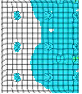
5 Prediction of Crack-width and Crack-pattern Page 5 Calculated and measured crack distances are in agreement. The calculated local crack-widths are of the same order as the measured average crackwidths and variations of crack-width over height of the beam show also similar trends between analysis results and measurements. Figures 7 and 10 display the stress in the reinforcement bars for both beams at a load of 209 kn. At this load-level the reinforcement stress is still below the yield-stress of steel. Stress concentration in the web-bar in Beam 6 can be clearly noticed. Figures 8 and 11 display the reduction factor of the stiffness for both beams at a load-level of 209 kn. Crack-patterns can be clearly recognised but are not so strongly pronounced as in the crack-width results. This example illustrates that Stiffness Adaptation Analysis can be used to predict crack-patterns and crack-width as well as deformations at serviceability loading levels in cross-sections of reinforced concrete beams. Analysis times are reasonable and analysis settings are straightforward. Flat Plate on Columns The next analysis-example is a pre-stressed reinforced concrete floor on columns that is loaded by set-of point-loads. diameter of 370 mm. For symmetry reasons only 1 quarter of the floor is modelled. In Figure 12 the positions of columns are coloured pink. The floor to column connection is modelled with linear interface elements. The 4 grey-coloured quadrilaterals in Figure 12 are the area s where a point-load-set is applied. The plate is modelled with quadratic shell elements with 7 integration-points over the thickness of the elements. The thickness of the plate is 190 mm and reinforcements grids of mm at top side (bars 8 mm diameter and 100 mm spacing) and mm at bottom side (9mm diameter and 150 mm spacing) In both directions are applied at both sides of the plate. First a prescribed displacement is applied at the outer edges, to simulate the shrinkage of the flat plate. This shrinkage load corresponds with a tensile force of 361 kn/m. Next the weight-load is applied, followed by a distributed load of 10 kn/m 2. Finally the point-loads are incremented. The material characteristics for the concrete are defined in the table 3. Young s modulus Poison ratio 0.2 Density Tensile strength 34 GPa 2500 kg/m3 3.2 MPa Tensile softening curve Crack Energy Compressive strength Compressive failure curve Linear 160 N/m 43 MPa Constant Table 3: Material parameters for concrete of Flat Plate on Columns. And the material parameters for steel are defined in table 4. Young s modulus 200 GPa Poisson ratio 0.3 Yield-stress 500 MPa Figure 12: Mesh of Flat Plate on Columns with boundary conditions and dimensions. The floor is rectangular with dimensions 11400*9500 mm and is resting on 30 columns with Table 4: Material parameters for steel reinforcements in Flat Plate on Columns. Shrinkage, weight and distributed load are applied in subsequent steps, without any failure of materials. Next the point-set load is applied in 50 steps up to a total load of 270 kn. The analysis takes circa 5 hours.


6 Prediction of Crack-width and Crack-pattern Page 6 Figure 13: Stiffness-reduction factor at top-surface (left) and bottom surface (right). Figure 14: crack-width distribution in mm at bottom surface.

7 Prediction of Crack-width and Crack-pattern Page 7 Figure 13 displays the stiffness-reduction at the top-surface and at the bottom surface of the flatplate. At the top-surface, cracking is initiated above the columns in diagonal direction, and with increasing loading, the cracks develop to arches around the areas where the sets of point-loads are applied. At the bottom surface, cracks are initiated in horizontal direction underneath the point-loads and with increasing loadings an additional vertical crack appears connecting the different sets of point-loads. In Figure 14 the crack-width distribution at the bottom surface is shown. Crack-widths at the topsurface were small and therefore not displayed. In the bottom surface at 270 kn loading, the width of main cracks is up to 0.2 mm. At this load-level the reinforcement grids are still in the elastic regime. This example illustrates that Stiffness Adaptation Analysis can be used to predict crack-patterns and crack-width and onset of reinforcement yielding at serviceability loading levels in plate-type of structures. Analysis times are reasonable and analysis settings are straight-forward. 3D Masonry Structure Full scale masonry structure tested by Yi et al. [2,3] is used as reference in the next analysis. In this experiment, a two-story unreinforced masonry structures, approximately 7.5 m square 7.1 m tall, was constructed and then tested under cyclic loading. For details of the experimental procedure, the reader is referred to [2,3]. De Jong et al. used the same reference for comparison with Sequential Linear Analysis and reported results in [4]. displacements being fixed at 80% of the two equal roof displacements. Prescribed displacements are always applied such that they lead to compressive reaction forces. Therefore, the supported degrees of freedom are different for both displacement directions. Because, Stiffness Adaptation Analysis in DIANA cannot at the moment be combined with Construction stage analysis, the cyclic loading experiments were simulated in two separate analyses by monotonic loading in the positive and negative x-direction. Results from both analyses were then combined to get an envelope for comparison with cyclic loading curves. First, the weight load and the post-tensioning forces are applied in 1 step. Then the horizontal displacements were applied in 60 equal sized steps of 0.1 mm for the top-points. A maximum of 10 iterations for each load-step were defined. The 3D building was defined with 4-node quadrilateral shell elements with 4 integration points in the plane and 3 integration points in thickness direction. Material properties for the masonry structures were defined as depicted in table 5. Thickness of the masonry was chosen equal to 250 mm. Young s modulus 6.9 GPa Poison ratio 0.25 Density Tensile strength Tensile softening curve 1920 kg/m3 0.2 MPa Linear Crack Energy Compressive strength Compressive failure curve 35 N/m 2 MPa Constant Figure 15: Geometry and loading conditions for model of Yi et al. [2] test. Figure 15 shows the outline of the building. First post-tensioning forces Pt were applied to the structures at 8 points, followed by a cyclic loading at the same locations as where the post-tensioning forces are acting. Cyclic loading was applied in displacement control, with the two equal floor Table 5 Material parameters for masonry elements in 3D Masonry structure. The floor and roof are, as line-loads, acting to the walls with values equivalent to density of 450 kg/m3 and thickness of 200 mm. Analysis time was circa 40 minutes per direction. Figure 16 depicts the measured cracks after full cyclic loading in both directions as reported by Yi et al. [4]. Figures 17 and 18 display crack-patterns, as reported by De Jong et al., for loading in + direction and in direction, respectively. Figures 19 and 20 display crack-width results in the outersurfaces of the walls at maximum loading (6 mm) for both loading directions.


![in [5] in + loading direction.](/docs-images/81/82862700/images/8-5.jpg "Figure 18: Cracks as results")
![in [5] in - loading direction.](/docs-images/81/82862700/images/8-6.jpg "Figure 19: Cracks as result")


8 Prediction of Crack-width and Crack-pattern Page 8 Figure 16: Measured cracks at loading in 2 directions Figure 17: Cracks as results from Sequential Linear Analysis reported by de Jong et al. in [5] in + loading direction. Figure 18: Cracks as results from Sequential Linear Analysis reported by de Jong et al. in [5] in - loading direction. Figure 19: Cracks as result from Stiffness Adaptation Analysis in + loading direction at 6 mm prescribed displacements. Figure 20 Cracks as result from Stiffness Adaptation Analysis in + loading direction at 6 mm prescribed displacements.
![Base shear force [kn] Base shear force [kn] Prediction of Crack-width and Crack-pattern Page 9 The major crack wrapping from the top of the doorportal in Wall1 to the right-hand upper window in WallA](/docs-images/81/82862700/images/9-0.jpg "can be recognised in Figure 16 and in both Sequential Linear Analysis and Stiffness Adaptation Analysis results with loading in + direction (Figures 18 and 20).")

![roof displacement: wall 1 DIANA Paper (3D shell) 600 400 200 0-10 -5 0 5 10-200 -400-600 Roof displacement [mm] Figure 21: Base shear versus roof-displacements for wall1 agreement in initial](/docs-images/81/82862700/images/9-2.jpg "stiffness and reasonable agreement in maximum shear-force capacity.")

9 Base shear force [kn] Base shear force [kn] Prediction of Crack-width and Crack-pattern Page 9 The major crack wrapping from the top of the doorportal in Wall1 to the right-hand upper window in WallA can be recognised in Figure 16 and in both Sequential Linear Analysis and Stiffness Adaptation Analysis results with loading in + direction (Figures 18 and 20). A major crack starting at the footing of the door-portal in Wall1 and wrapping to the left-hand upper window in WallB can be recognised in both analysis results for loading in direction, but not in the Figure 16. As De Jong [5] writes, this discrepancy is likely to be the result of simplified monotonic loading. Base shear vs. roof displacement: wall 1 DIANA Paper (3D shell) Roof displacement [mm] Figure 21: Base shear versus roof-displacements for wall1 agreement in initial stiffness and reasonable agreement in maximum shear-force capacity. 3D Viaduct One 60 meters segment of a single span out of a 15 spandouble-box-girder viaduct (986 m length in total) is used as basis for the last example of this paper. In the bridge segment an expansion-joint is defined and both parts are connected with a rigid dowel. Cracks in the concrete body were noticed during inspection and analyses have been performed to assess crack development and the stability of the bridge at load-levels between serviceability and ultimate limit state. A 3-dimensional finite element model of solid elements was defined for the concrete body, taking into account construction details, such as variations of thickness of flanges and walls of the box, man-hole-openings and anchor-bolts. The finite element models consists of circa lower order elements, mainly of brick-type. A series of pre-tensioning cables is defined in each of the walls of the boxes. A very detailed representation of the steel reinforcements in the box-girder was considered, such as longitudinal bars in the box, transverse bars in the top-flange, curved pre-tension cables in the end-plates, grids at all outer faces of the concrete body, and others. The total number of reinforcement particles in this model is around Base shear vs. roof displacement: wall 2 DIANA Paper (3D shell) Roof displacement [mm] Figure 22: Base shear versus roof-displacements for wall2 Figures 21 and 22 show the displacement reaction force curves as measured by Li et al. [4] and as calculated by Stiffness Adaptation Analysis for Wall 1 and Wall2 respectively. Both results show good Figure 23: Part of the concrete body of the box-girder viaduct with selected of reinforcements in the structure. Figure 24: Front view of box-girder viaduct with splitted view.

10 Prediction of Crack-width and Crack-pattern Page 10 Concrete was defined with linear softening in tension and constant maximum stress in compression. Steel reinforcements were defined with constant maximum stress in both tension and compression. Both parts were connected with rigid interface elements in the joint. The viaduct was supported in 4 corner points on elastic interface elements. Further, all the nodes in the longitudinal endplanes are supported in axial direction. The load was applied as follows: First the weight-load and pre-stressing of the longitudinal cables in the walls of the box were applied in 10 increments. Then the P-mobile load was applied in 10 increments. The P-load is positioned as 6 rectangular pressure field eccentrically on the shorter part of the model close to the joint. P- load is defined according Eurocode. Then the Q-mobile load in 30 increments of 10% each. The Q-mobile load is defined as pressure load on the full top-surface of the segment and is defined according to Eurocode. No construction stages have been considered. A stiffness-adaptation analysis has been performed on a dual Intel Xeon X5550 quad-core 2.66GHz, 48 GB memory, Linux platform with elapsed time of 10 hours. Figure 27: Crack pattern with crack-widths after weight load and pre-tensioning load, 1x P-Mobile and 3x Q-mobile (detail from bottom left direction). 3xQ-mobile 2xQ-mobile 1xQ-mobile P-mobile Weigh + Pretensioning Unloaded Vertical displacement of mid-slab joint point [m] Figure 25: Crack pattern with crack-widths after weight laod and pre-tensioning load. Figure 26: Crack pattern with crack-widths after weight load and pre-tensioning load, 1x P-Mobile and 3x Q-mobile (from topright direction). Figure 28: Vertical displacement of position next to the joint at mid-point of top-deck. Figures 25 and 26 display crack-patterns and crack-widths in the box-girder after application of weight and pre-tensioning loading (Figure 25) and after application of 3xQ-mobile (Figure 26). After initial loading the maximum crack-width is limited to 0.1 mm and small cracks are found locally at transitions from the top and the bottom flange and the walls of the box-girder. When the full loading (3x Q-mobile) is applied severe horizontal, slightly diagonal, cracks are found in the walls of the shorter part of the viaduct segment. Crack-width in the wall at the side of the bridge at which P-mobile is applied is of order of 1 mm whereas in the middle wall of the box-girder the crack-width are limited to 0.4 mm in the mid-span and 0.2 mm in the right-hand-side span). Figure 27 shows that at 3x Q-mobile loading a diagonal crack propagates through the upper-
11 Prediction of Crack-width and Crack-pattern Page 11 Figure 29: Vertical stresses in reinforcement grids in walls and crack-widths at different load-levels.
12 Prediction of Crack-width and Crack-pattern Page 12 flange initiating at the corner connection of topflange, end-plate and left-hand-side wall. Figure 28 shows the development of vertical displacements of a node positioned in the middle of the top-flange close to the joint as function of 5 loading conditions. With the progressing of cracks the displacement develops progressively in the three last bars with constant increase of loads. The figure 29 shows a selection of stresses in reinforcement grids with corresponding crackpatterns in the shorter part of the box-girder box. References [1] HERON Nr. 35, 1990, C.R. Braam, Control of Crack-width in Deep Reinforced Concrete Beams [2] Yi T., Large-scale testing of a two-story URM structure, Ph.D. dissertation Georgia Institute of Technology, [3] Yi T., Moon F.L., Leon R.T., Kahn L.F., Lateral load tests on a two-story unreinforced masonry building, ASCE J. Struct. Eng 2006: 132(5): [4] De Jong M.J., Belletti, B., Hendriks M.A.N., Rots, J.G., Shell elements for sequential linear analysis: Lateral failure of masonry structures, Engng. Structures 31 (2009)
Nonlinear Finite Element Modeling & Simulation
 Full-Scale Structural and Nonstructural Building System Performance during Earthquakes & Post-Earthquake Fire A Joint Venture between Academe, Industry and Government Nonlinear Finite Element Modeling
Chapter 7. Finite Elements Model and Results
 Chapter 7 Finite Elements Model and Results 7.1 Introduction In this chapter, a three dimensional model was presented. The analytical model was developed by using the finite elements method to simulate
INFLUENCE OF PRSTRESS LEVEL ON SHEAR BEHAVIOR OF SEGMENTAL CONCRETE BEAMS WITH EXTERNAL TENDONS
 - Technical Paper - INFLUENCE OF PRSTRESS LEVEL ON SHEAR BEHAVIOR OF SEGMENTAL CONCRETE BEAMS WITH EXTERNAL TENDONS Dinh Hung NGUYEN *1, Ken WATANABE *2, Junichiro NIWA *3 and Tsuyoshi HASEGAWA *4 ABSTRACT
NONLINEAR FINITE ELEMENT ANALYSIS OF SHALLOW REINFORCED CONCRETE BEAMS USING SOLID65 ELEMENT
 NONLINEAR FINITE ELEMENT ANALYSIS OF SHALLOW REINFORCED CONCRETE BEAMS USING SOLID65 ELEMENT M. A. Musmar 1, M. I. Rjoub 2 and M. A. Abdel Hadi 1 1 Department of Civil Engineering, Al-Ahliyya Amman University,
Nonlinear Finite Element Analysis of Composite Cantilever Beam with External Prestressing
 Nonlinear Finite Element Analysis of Composite Cantilever Beam with External Prestressing R. I. Liban, N. Tayşi 1 Abstract This paper deals with a nonlinear finite element analysis to examine the behavior
Creep Response of a Prestressed Concrete Beam under Sustained Load
 Creep Response of a Prestressed Concrete Beam under Sustained Load Outline 1 Description 2 Finite Element Model 2.1 Units 2.2 Geometry Definition 2.3 Boundary Constraints 2.4 Properties 2.4.1 Concrete
Assessment of Non-Linear Static Analysis of Irregular Bridges
 Assessment of Non-Linear Static Analysis of Irregular Bridges M JARA, JO NAVARRO, JM JARA AND BA OLMOS Civil Engineering Department University of Michoacán Avenida Francisco J. Múgica s/n, Ciudad Universitaria.
CHAPTER 7 ANALYTICAL PROGRAMME USING ABAQUS
 87 CHAPTER 7 ANALYTICAL PROGRAMME USING ABAQUS 7.1 GENERAL With the advances in modern computing techniques, finite element analysis has become a practical and powerful tool for engineering analysis and
Fagà, Bianco, Bolognini, and Nascimbene 3rd fib International Congress
 COMPARISON BETWEEN NUMERICAL AND EXPERIMENTAL CYCLIC RESPONSE OF ALTERNATIVE COLUMN TO FOUNDATION CONNECTIONS OF REINFORCED CONCRETEC PRECAST STRUCTURES Ettore Fagà, Dr, EUCENTRE, Pavia, Italy Lorenzo
Effect of Flange Width on Flexural Behavior of Reinforced Concrete T-Beam
 Effect of Flange Width on Flexural Behavior of Reinforced Concrete T-Beam Ofonime A. Harry Institute for Infrastructure and Environment, University of Edinburgh, UK Department of Civil Engineering Ndifreke
Structural Nonlinear Analysis of a Shear Wall Panel
 Structural Nonlinear Analysis of a Shear Wall Panel analys: linear static. constr: suppor. elemen: cq16m ct12m pstres. load: force node. materi: elasti isotro. option: direct units. post: binary ndiana.
Sabah Shawkat Cabinet of Structural Engineering 2017
 3.1-1 Continuous beams Every building, whether it is large or small, must have a structural system capable of carrying all kinds of loads - vertical, horizontal, temperature, etc. In principle, the entire
Nonlinear Models of Reinforced and Post-tensioned Concrete Beams
 111 Nonlinear Models of Reinforced and Post-tensioned Concrete Beams ABSTRACT P. Fanning Lecturer, Department of Civil Engineering, University College Dublin Earlsfort Terrace, Dublin 2, Ireland. Email:
Numerical and Experimental Behaviour of Moment Resisting Connections using Blind Bolts within CFSHS columns
 Proceedings of the Tenth Pacific Conference on Earthquake Engineering Building an Earthquake-Resilient Pacific 6-8 November 2015, Sydney, Australia Numerical and Experimental Behaviour of Moment Resisting
BOUNDARY CONDITIONS OF SHEAR WALLS IN MULTI-STOREY MASONRY STRUCTURES UNDER HORIZONTAL LOADINGS
 BOUNDARY CONDITIONS OF SHEAR WALLS IN MULTI-STOREY MASONRY STRUCTURES UNDER HORIZONTAL LOADINGS K. ZILCH Professor, Institute of Building Materials and Structures Chair of Concrete Structures Technische
BUCKLING ANALYSIS OF PULTRUDED GFRP HOLLOW BOX BEAM
 BUCKLING ANALYSIS OF PULTRUDED GFRP HOLLOW BOX BEAM Donna CHEN Ph.D. Candidate University of Calgary, Department of Civil Engineering 2500 University Drive NW, Calgary, Alberta, T2N 1N4, Canada dsmchen@ucalgary.ca
Level 6 Graduate Diploma in Engineering Structural analysis
 9210-111 Level 6 Graduate Diploma in Engineering Structural analysis Sample Paper You should have the following for this examination one answer book non-programmable calculator pen, pencil, ruler, drawing
Shrinkage Effects on a Concrete Slab on Ground
 Shrinkage Effects on a Concrete Slab on Ground Outline 1 Description 2 Finite Element Model 2.1 Units 2.2 Geometry Definition 2.3 Properties 2.3.1 Concrete slab 2.3.2 Grid reinforcement 2.3.3 Soil interface
Non Linear Analysis of Composite Beam Slab Junction with Shear Connectors using Ansys.16
 International Journal of Engineering Science Invention ISSN (Online): 2319 6734, ISSN (Print): 2319 6726 Volume 5 Issue 4 April 2016 PP.22-29 Non Linear Analysis of Composite Beam Slab Junction with Shear
Introduction to Structural Analysis TYPES OF STRUCTURES LOADS AND
 AND Introduction to Structural Analysis TYPES OF STRUCTURES LOADS INTRODUCTION What is the role of structural analysis in structural engineering projects? Structural engineering is the science and art
Tests of R/C Beam-Column Joint with Variant Boundary Conditions and Irregular Details on Anchorage of Beam Bars
 October 1-17, 8, Beijing, China Tests of R/C Beam-Column Joint with Variant Boundary Conditions and Irregular Details on Anchorage of Beam Bars F. Kusuhara 1 and H. Shiohara 1 Assistant Professor, Dept.
Repair and Retrofit of a 17 th Century Library Structure in Istanbul
 Repair and Retrofit of a 17 th Century Library Structure in Istanbul Sesigur, H. & Cili, F. Istanbul Technical University, Turkey SUMMARY: In the present study a heavily damaged 17th century library structure
REVIEW ON SHEAR SLIP OF SHEAR KEYS IN BRIDGES
 REVIEW ON SHEAR SLIP OF SHEAR KEYS IN BRIDGES Benjamin Raison R; Freeda Christy C PG student, School of Civil Engineering, Karunya University. Associate Professor, School of Civil Engineering, Karunya
Load capacity rating of an existing curved steel box girder bridge through field test
 109 Dongzhou Huang Senior Engineer IV TS Transportation Design South Florida Atkins North America Load capacity rating of an existing curved steel box girder bridge through field test Abstract This paper
Nonlinear Redundancy Analysis of Truss Bridges
 Nonlinear Redundancy Analysis of Truss Bridges Analysis Report Dr. Michel Ghosn Ph.D. Graziano Fiorillo The City College of New York / CUNY SEPTEMBER 2013 Acknowledgments This section describes the redundancy
3-D FINITE ELEMENT ANALYSIS OF PILE-TO-PILE CAP CONNECTIONS SUBJECTED TO SEISMIC ACTION
 3-D FINITE ELEMENT ANALYSIS OF PILE-TO-PILE CAP CONNECTIONS SUBJECTED TO SEISMIC ACTION M. Teguh 1,2), C.F. Duffield 1), P. A. Mendis 1), G.L. Hutchinson 1) 1) University of Melbourne, Melbourne, Victoria
MODELING OF SPANDREL ELEMENTS IN URM STRUCTURES WITH RC SLABS OR RING BEAMS. Abstract
 MODELING OF SPANDREL ELEMENTS IN URM STRUCTURES WITH RC SLABS OR RING BEAMS K. Beyer 1 and A. Dazio 2 Abstract In many unreinforced masonry (URM) buildings, reinforced concrete (RC) slabs or ring beams
THE EFFECT OF THE TYPES OF SUPPORTS IN THE DISTRIBUTION OF LOADS BETWEEN THE GIRDERS OF THE BRIDGE
 THE EFFECT OF THE TYPES OF SUPPORTS IN THE DISTRIBUTION OF LOADS BETWEEN THE GIRDERS OF THE BRIDGE Mohammed Hassan, Khalil AL-Bukhaiti * and Deshan Shan School of Civil Engineering, south west Jiaotong
Elasto-plastic behavior of steel frame structures taking into account buckling damage
 Elasto-plastic behavior of steel frame structures taking into account buckling damage Hamid Afzali 1, Toshitaka Yamao 2, AkiraKasai 3 and Keizo Yamamoto 4 1 Kumamoto University, Kumamoto, Japan, h.afzali@gmail.com
MASONRY INSIGHTS. Finite Element Modeling, Analysis, and Design for Masonry. Introduction
 MASONRY INSIGHTS Finite Element Modeling, Analysis, and Design for Masonry Software programs for structural engineers continue to escalate in complexity as we continue to become increasingly reliant on
Jason Ingham, Manicka Dhanasekar & Mark Masia
 Proceedings of the 9th Australasian Masonry Conference Queenstown, New Zealand 15-18 February 211 Editors: Jason Ingham, Manicka Dhanasekar & Mark Masia Copyright 211 Proceedings of the 9 th Australasian
CHAPTER 5 FINITE ELEMENT MODELLING
 53 CHAPTER 5 FINITE ELEMENT MODELLING 5.1 GENERAL Reinforced concrete structures are largely employed in engineering practice in a variety of situations and applications. In most cases these structures
CHAPTER 7 FINITE ELEMENT ANALYSIS
 189 CHAPTER 7 FINITE ELEMENT ANALYSIS 7.1 SCOPE In Engineering applications, the physical response of the structure to the system of external forces is very much important. Understanding the response of
7 LOCAL BUCKLING OF STEEL CLASS 4 SECTION BEAMS
 Jan Hricák, jan.hricak@fsv.cvut.cz WG3 - Michal Jandera, michal.jandera@fsv.cvut.cz WG2 František Wald, wald@fsv.cvut.cz 7 LOCAL BUCKLING OF STEEL CLASS 4 SECTION BEAMS Summary A significant progress in
Girder-End Cracking in Prestressed I-Girders
 Girder-End Cracking in Prestressed I-Girders T. Patrick Earney Department of Civil and Environmental Engineering, University of Missouri Columbia, Columbia, MO, USA 65211 1. Introduction There has been
Bond-slip of Post-tensioned Reinforcement in 2D elements
 Y X Bond-slip of Post-tensioned Reinforcement in 2D elements ANALYS keywords: nonlin phase physic CLASS keywords: large CONSTR keywords: suppor tying ELEMEN keywords: bar bondsl cable cl6tr cq16m cq22if
THE BEHAVIOR OF TWO MASONRY INFILLED FRAMES: A NUMERICAL STUDY
 THE BEHAVIOR OF TWO MASONRY INFILLED FRAMES: A NUMERICAL STUDY Giselle M. Fonseca *, Roberto M. Silva *, and Paulo B. Lourenço # * University Federal of Minas Gerais, School of Engineering Department of
UNIVERSITY OF PADUA ITALY Dept. Civil Environmental Arch. Eng. UNIVERSITY OF CALIFORNIA BERKELEY Dept. Civil and Environmental Eng.
 UNIVERSITY OF PADUA ITALY Dept. Civil Environmental Arch. Eng. UNIVERSITY OF CALIFORNIA BERKELEY Dept. Civil and Environmental Eng. Cyclic Inelastic Analysis of RC Shear Walls and Plates Leopoldo Tesser
Interaction between ductile RC perimeter frames and floor slabs containing precast units
 Interaction between ductile RC perimeter frames and floor slabs containing precast units R. C Fenwick,. J. Davidson and D.. N. Lau Department of Civil and Environmental Engineering, University of uckland.
NON-LINEAR FEM ANALYSIS FOR CES SHEAR WALLS
 1NCEE Tenth U.S. National Conference on Earthquake Engineering Frontiers of Earthquake Engineering July 21-25, 214 Anchorage, Alaska NON-LINEAR FEM ANALYSIS FOR CES SHEAR WALLS S. SUZUKI 1, H. KURAMOTO
Analytical Modeling of the Contribution of Transverse Reinforcement in Prestressed Concrete Bridge Girders
 Analytical Modeling of the Contribution of Transverse Reinforcement in Prestressed Concrete Bridge Girders Katie Boris, REU Student Padmanabha Rao Tadepalli, Graduate Mentor Y. L. Mo, Faculty Advisor Final
Office Building-G. Thesis Proposal. Carl Hubben. Structural Option. Advisor: Dr. Ali Memari
 Office Building-G Thesis Proposal Structural Option December 10, 2010 Table of Contents Executive Summary... 3 Introduction... 4 Gravity System...4 Lateral System:...6 Foundation System:...6 Problem Statement...
Progressive Collapse Resisting Capacity of Moment Frames with Infill Steel Panels
 Paper 23 Progressive Collapse Resisting Capacity of Moment Frames with Infill Steel Panels M.H. Lee, H. Lee and J.K. Kim Department of Architectural Engineering Sungkyunkwan University, Suwon, Korea Civil-Comp
Damage assessment of hollow core reinforced and prestressed concrete slabs subjected to blast loading
 Available online at www.sciencedirect.com ScienceDirect Procedia Engineering 199 (2017) 2476 2481 X International Conference on Structural Dynamics, EURODYN 2017 Damage assessment of hollow core reinforced
BEHAVIOR OF REINFORCED CONCRETE BEAM WITH OPENING
 International Journal of Civil Engineering and Technology (IJCIET) Volume 8, Issue 7, July 2017, pp. 581 593, Article ID: IJCIET_08_07_062 Available online at http:// http://www.iaeme.com/ijciet/issues.asp?jtype=ijciet&vtype=8&itype=7
NEW COMPOSITE CONSTRUCTION OF HYBRID BEAMS COMBINING STEEL INVERTED T-SECTION AND RC FLANGE
 NEW COMPOSITE CONSTRUCTION OF HYBRID BEAMS COMBINING STEEL INVERTED T-SECTION AND RC FLANGE Alex Remennikov 1, Marcus Roche 2 ABSTRACT: Steel and concrete composite beams are typically formed by shear
ATENA Program Documentation Part 4-8
 Červenka Consulting s.r.o. Na Hrebenkach 55 150 00 Prague Czech Republic Phone: +420 220 610 018 E-mail: cervenka@cervenka.cz Web: http://www.cervenka.cz ATENA Program Documentation Part 4-8 ATENA Science
PRESTRESSED CONCRETE STRUCTURES. Amlan K. Sengupta, PhD PE Department of Civil Engineering Indian Institute of Technology Madras
 PRESTRESSED CONCRETE STRUCTURES Amlan K. Sengupta, PhD PE Department of Civil Engineering Indian Institute of Technology Madras Module 5: Analysis and Design for Shear and Torsion Lecture-23: Analysis
ST7008 PRESTRESSED CONCRETE
 ST7008 PRESTRESSED CONCRETE QUESTION BANK UNIT-I PRINCIPLES OF PRESTRESSING PART-A 1. Define modular ratio. 2. What is meant by creep coefficient? 3. Is the deflection control essential? Discuss. 4. Give
Modeling and Design of Bridge Super Structure and Sub Structure
 Topic 3 Day 2 Modeling and Design of Bridge Super Structure and Sub Structure Naveed Anwar 1. Over view of Bridge Design Process and Bridge Types 2. Advances and recent trends in Modeling and Analysis
Nonlinear Analysis of Reinforced Concrete Column with ANSYS
 Nonlinear Analysis of Reinforced Concrete Column with ANSYS V. S. Pawar 1, P. M. Pawar 2 1P.G. Student, Dept. Of civil Engineering, SVERI s College of Engineering Pandharpur, Maharashtra, India 2Professor,
PUSHOVER ANALYSIS (NON-LINEAR STATIC ANALYSIS) OF RC BUILDINGS USING SAP SOFTWARE
 OF RC BUILDINGS USING SAP SOFTWARE") PUSHOVER ANALYSIS (NON-LINEAR STATIC ANALYSIS) OF RC BUILDINGS USING SAP SOFTWARE PROJECT REFERENCE NO. : 37S0221 COLLEGE : DAYANANDA SAGAR COLLEGE OF ENGINEERING, BANGALORE BRANCH : CIVIL ENGINEERING
PUSHOVER ANALYSIS (NON-LINEAR STATIC ANALYSIS) OF RC BUILDINGS USING SAP SOFTWARE PROJECT REFERENCE NO. : 37S0221 COLLEGE : DAYANANDA SAGAR COLLEGE OF ENGINEERING, BANGALORE BRANCH : CIVIL ENGINEERING
Steel-Fibre-Reinforced Concrete Pavements
 Concrete Communication Conference 1-2 September 2008, University of Liverpool Steel-Fibre-Reinforced Concrete Pavements Naeimeh Jafarifar, Kypros Pilakoutas, Kyriacos Neocleous Department of Civil and
Application of Fiber Model for Progressive Collapse Analysis of Reinforced Concrete Frames *
 Application of Fiber Model for Progressive Collapse Analysis of Reinforced Concrete Frames * Xinzheng Lu, Yi Li, Lieping Ye and Yi Liang Department of Civil Engineering, Tsinghua University, Beijing 100084,
1514. Structural behavior of concrete filled carbon fiber reinforced polymer sheet tube column
 1514. Structural behavior of concrete filled carbon fiber reinforced polymer sheet tube column Kyoung Hun Lee 1, Heecheul Kim 2, Jaehong Kim 3, Young Hak Lee 4 1 Provincial Fire and Disaster Headquarters,
3D analysis of solid reinforced concrete beams subjected to combined load of bending, torsion and shear
 ational Methods and Experimental Measurements XIII 85 3D analysis of solid reinforced concrete beams subjected to combined load of bending, torsion and shear A. S. Alnuaimi Civil and Architectural Engineering,
ANALYTICAL STUDY OF PUNCHING SHEAR ON WAFFLE SLAB WITH DIFFERENT RIB SIZES
 Jr. of Industrial Pollution Control 33(S2)(27) pp 323-327 www.icontrolpollution.com Research Article ANALYTICAL STUDY OF PUNCHING SHEAR ON WAFFLE SLAB WITH DIFFERENT RIB SIZES K. SAKETH*, C. ARUNKUMAR
CHAPTER 6 FINITE ELEMENT ANALYSIS
 105 CHAPTER 6 FINITE ELEMENT ANALYSIS 6.1 INTRODUCTION Several theoretical approaches are considered to analyze the yielding and buckling failure modes of castellated beams. Elastic Finite Element Analysis
5.4 Analysis for Torsion
 5.4 Analysis for Torsion This section covers the following topics. Stresses in an Uncracked Beam Crack Pattern Under Pure Torsion Components of Resistance for Pure Torsion Modes of Failure Effect of Prestressing
A comparison of numerically and experimentally obtained in-plane responses of a full-scale unreinforced masonry building frame
 Proceedings of the Tenth Pacific Conference on Earthquake Engineering Building an Earthquake-Resilient Pacific 6-8 November 2015, Sydney, Australia A comparison of numerically and experimentally obtained
The Use of Sustainable Materials for Quick Repair of Aging Bridges
 The Use of Sustainable Materials for Quick Repair of Aging Bridges Phase II Final Report PI: Azadeh Parvin, D.Sc. Associate Professor Department of Civil Engineering College of Engineering Prepared for
SIMPLE INVESTIGATIONS OF TENSILE MEMBRANE ACTION IN COMPOSITE SLABS IN FIRE
 SIMPLE INVESTIGATIONS OF TENSILE MEMBRANE ACTION IN COMPOSITE SLABS IN FIRE By Ahmed Allam 1, Ian Burgess 1 and Roger Plank 1 Department of Civil and Structural Engineering, University of Sheffield, UK
Modeling stiffener distortion in orthotropic bridge decks with FEM using superelements
 Modeling stiffener distortion in orthotropic bridge decks with FEM using superelements C. Delesie 1 & P. Van Bogaert 1 1 Civil engineering department, Ghent university, Ghent,Belgium ABSTRACT: Modern design
In-plane testing of precast concrete wall panels with grouted sleeve
 In-plane testing of precast concrete wall panels with grouted sleeve P. Seifi, R.S. Henry & J.M. Ingham Department of Civil Engineering, University of Auckland, Auckland. 2017 NZSEE Conference ABSTRACT:
by Dr. Evert Hoek prepared for RocNews - Spring 2011
 by Dr. Evert Hoek prepared for RocNews - Spring 2011 Cavern Reinforcement and Lining Design by Evert Hoek 2 April 2011 Introduction This note has been prepared in response to a technical support question
MODELLING OF SHEAR WALLS FOR NON-LINEAR AND PUSH OVER ANALYSIS OF TALL BUILDINGS
 MODELLING OF SHEAR WALLS FOR NON-LINEAR AND PUSH OVER ANALYSIS OF TALL BUILDINGS Naveed Anwar 1, Thaung Htut Aung 2 ABSTRACT: The Performance Based Analysis and design of buildings and structures, especially
Strut and tie. Betongbyggnad VBKN05
 Strut and tie Betongbyggnad VBKN05 Strut and Tie Design the deep beam (hög balk) in the figure. qd = 200 kn/m 3 m 3 m Strut and Tie Strut and Tie Describe the stresses in a concrete structure with a strut
INTERNATIONAL JOURNAL OF CIVIL AND STRUCTURAL ENGINEERING Volume 2, No 2, 2011
 INTERNATIONAL JOURNAL OF CIVIL AND STRUCTURAL ENGINEERING Volume 2, No 2, 2011 Copyright 2010 All rights reserved Integrated Publishing services Research article ISSN 0976 4399 Nonlinear Seismic Behavior
INTERNATIONAL JOURNAL OF CIVIL AND STRUCTURAL ENGINEERING Volume 3, No 1, 2012
 INTERNATIONAL JOURNAL OF CIVIL AND STRUCTURAL ENGINEERING Volume 3, No 1, 2012 Copyright by the authors - Licensee IPA- Under Creative Commons license 3.0 Research article ISSN 0976 4399 Finite element
Finite Element Analysis of Slender Composite Column Subjected to Eccentric Loading
 Finite Element Analysis of Slender Composite Column Subjected to Eccentric Loading *Yonas T.Y. 1, Temesgen W. 2, Senshaw F.W. 3 1 Lecturer, School of Civil Engineering and Architecture, Dire Dawa Institute
Modelling of RC moment resisting frames with precast-prestressed flooring system
 Modelling of RC moment resisting frames with precast-prestressed flooring system B.H.H. Peng, R.P. Dhakal, R.C. Fenwick & A.J. Carr Department of Civil Engineering, University of Canterbury, Christchurch.
Case Study: Challenges of a Single-layer Reticulated Dome
 Case Study: Challenges of a Single-layer Reticulated Dome Naveed Anwar, Pramin Norachan, Thaung Htut Aung AIT Consulting, Asian Institute of Technology, Bangkok, Thailand Contact: nanwar@ait.asia Abstract
Transactions on the Built Environment vol 20, 1996 WIT Press, ISSN
 A two-storey masonry wall under seismic loading: a numerical comparison between simple and strengthened masonry U. Andreaus, L. Ippoliti Dipertimento di Ingegneria Strutturale e Geotecnica, Facoltd di
Structural Characteristics of New Composite Girder Bridge Using Rolled Steel H-Section
 Proc. Schl. Eng. Tokai Tokai Univ., Univ., Ser. ESer. E 41 (2016) (2016) - 31-37 Structural Characteristics of New Composite Girder Bridge Using Rolled Steel H-Section by Mohammad Hamid ELMY *1 and Shunichi
BS EN :2004 EN :2004 (E)
") Contents List 1. General 1.1 Scope 1.1.1 Scope of Eurocode 2 1.1.2 Scope of Part 1-1 of Eurocode 2 1.2 Normative references 1.2.1 General reference standards 1.2.2 Other reference standards 1.3 Assumptions
Contents List 1. General 1.1 Scope 1.1.1 Scope of Eurocode 2 1.1.2 Scope of Part 1-1 of Eurocode 2 1.2 Normative references 1.2.1 General reference standards 1.2.2 Other reference standards 1.3 Assumptions
Analysis of Buried Arch Structures; Performance Versus Prediction
 Analysis of Buried Arch Structures; Performance Versus Prediction D.A. Jenkins: Reinforced Earth Pty Ltd, Somersby, NSW, Australia Synopsis: The Reinforced Earth Group introduced the TechSpan arch system
Journal of Asian Scientific Research EVALUATION OF RECTANGULAR CONCRETE-FILLED STEEL-HOLLOW SECTION BEAM-COLUMNS
 Journal of Asian Scientific Research journal homepage: http://www.aessweb.com/journals/5003 EVALUATION OF RECTANGULAR CONCRETE-FILLED STEEL-HOLLOW SECTION BEAM-COLUMNS Kamyar Bagherinejad 1 ---- Emad Hosseinpour
Nonlinear Analysis of Shear Dominant Prestressed Concrete Beams using ANSYS
 Nonlinear Analysis of Shear Dominant Prestressed Concrete Beams using ANSYS Job Thomas Indian Institute of Science, Bangalore, India Ananth Ramaswamy Indian Institute of Science, Bangalore, India Abstract
SHEAR BEHAVIOR OF MULTI-STORY RC STRUCTURAL WALLS WITH ECCENTRIC OPENINGS
 SHEAR BEHAVIOR OF MULTI-STORY RC STRUCTURAL WALLS WITH ECCENTRIC OPENINGS Makoto Warashina 1, Susumu Kono 2, Masanobu Sakashita 3, Hitoshi Tanaka 4 1 Ex-Graduate Student, Dept. of Architecture and Architectural
CADS A3D MAX. How to model shear walls
 CADS A3D MAX How to model shear walls Modelling shear walls in A3D MAX Introduction and synopsis This paper explains how to model shear walls in A3D MAX using the `wide column rigid arm sub-frame described
BEHAVIOUR OF REINFORCED CONCRETE STRUCTURES IN FIRE
 BEHAVIOUR OF REINFORCED CONCRETE STRUCTURES IN FIRE ZHAOHUI HUANG, IAN W. BURGESS and ROGER J. PLANK 3 ABSTRACT In the past two decades, a significant amount of research has been conducted into the performance
Three Dimensional Modeling of Masonry Structures and Interaction of In- Plane and Out-of-Plane Deformation of Masonry Walls
 Three Dimensional Modeling of Masonry Structures and Interaction of In- Plane and Out-of-Plane Deformation of Masonry Walls Kiarash M. Dolatshahi a and Amjad J. Aref b a Ph.D Candidate, Department of Civil,
Abstract Introduction and Background Formulation Results and Discussion Conclusion and Future Work References...
 Table of Contents Abstract... 1 Introduction and Background... 2 Formulation... 3 Results and Discussion... 6 Conclusion and Future Work... 7 References... 8 Appendix A West Point Bridge Designer Truss
Effect of Infill as a Structural Component on the Column Design of Multi-Storied Building
 Effect of Infill as a Structural Component on the Column Design of Multi-Storied Building Hossain Mohammad Muyeed-Ul-Azam 1 and Khan Mahmud Amanat 2 Abstract The structural effect of brick infill is generally
Contents. Foreword 1 Introduction 1
 Contents Notation x Foreword xiii 1 Introduction 1 1.1 Aims of the Manual 1 1.2 Eurocode system 1 1.3 Scope of the Manual 3 1.4 Contents of the Manual 4 1.5 Notation and terminology 4 2 General principles
Shear and torsion interaction of hollow core slabs
 Competitive and Sustainable Growth Contract Nº G6RD-CT-2001-00641 Shear and torsion interaction of hollow core slabs HOLCOTORS Technical Report 1 Finite element analyses of hollow core units subjected
THE ANALYTICAL STUDY OF STRENGTHENING THE HORIZONTALLY CURVED STEEL BEAM WITH CFRP LAMINATES
 THE ANALYTICAL STUDY OF STRENGTHENING THE HORIZONTALLY CURVED STEEL BEAM WITH CFRP LAMINATES Hayder M.K. Al-Mutairee, PhD, Asst. Prof. Ali I. AbdulAbbas, B.Sc., M.Sc. Student Department of Civil Engineering,
PRELIMINARY FINITE ELEMENT ANALYSIS OF A MASONRY ARCH BRIDGE WITH NEAR-SURFACE REINFORCEMENT. Stephen.W.Garrity 1 and Irina L.
 PRELIMINARY FINITE ELEMENT ANALYSIS OF A MASONRY ARCH BRIDGE WITH NEAR-SURFACE REINFORCEMENT Stephen.W.Garrity 1 and Irina L.Toropova 1 ABSTRACT A three-dimensional finite element analysis of a typical
Optimum Dimensions of Suspension Bridges Considering Natural Period
 IOSR Journal of Mechanical and Civil Engineering (IOSR-JMCE) e-issn: 2278-1684,p-ISSN: 2320-334X, Volume 6, Issue 4 (May. - Jun. 2013), PP 67-76 Optimum Dimensions of Suspension Bridges Considering Natural
3D FINITE ELEMENT MODELS OF PLAIN AND BOND-BEAMED HOLLOW MASONRY WALLS SUBJECTED TO CONCENTRIC AND ECCENTRIC CONCENTRATED LOADS
 3D FINITE ELEMENT MODELS OF PLAIN AND BOND-BEAMED HOLLOW MASONRY WALLS SUBJECTED TO CONCENTRIC AND ECCENTRIC CONCENTRATED LOADS Junyi Yi 1 and Nigel G. Shrive 2 ABSTRACT 3-D finite element models have
コンクリート工学年次論文集,Vol.36,No.2, Technical Paper - A STUDY ON RESIDUAL CAPACITY OF REINFORCED CONCRETE CORBEL FAILED BY ANCHORAGE SPLITTING FAILURE Li
 コンクリート工学年次論文集,Vol.36,No.2,214 - Technical Paper - A STUDY ON RESIDUAL CAPACITY OF REINFORCED CONCRETE CORBEL FAILED BY ANCHORAGE SPLITTING FAILURE Liyanto EDDY *1, Kohei NAGAI 2, and Ram Chandra NEUPANE
Modelling of Reinforced Concrete Core Walls Under Bi-directional Loading
 Modelling of Reinforced Concrete Core Walls Under Bi-directional Loading R. Constantin & K. Beyer Ecole Polytechnique Fédérale de Lausanne (EPFL), Switzerland SUMMARY: Reinforced concrete core walls with
Scientific Seminar Design of Steel and Timber Structures SPbU, May 21, 2015
 Riga Technical University Institute of Structural Engineering and Reconstruction Scientific Seminar The research leading to these results has received the funding from Latvia state research programme under
CHAPTER 5 FINITE ELEMENT MODELING
 CHAPTER 5 FINITE ELEMENT MODELING 5.1 INTRODUCTION Masonry is a composite material with the building brick units and the mortar as the joining material, which are bonded together. Guinea [2000] 51 reported
Effect of U-Turn in Reinforced Concrete Dog-Legged Stair Slabs
 Effect of U-Turn in Reinforced Concrete Dog-Legged Stair Slabs Abdul Baqi and Zaid Mohammad Abstract Reinforced concrete stair slabs with mid s i.e. Dog-legged shaped are conventionally designed as per
Residual Strengths of Reinforced Concrete Beams With Heavy Deterioration
 Research Journal of Applied Sciences, Engineering and Technology 2(8): 798-805, 2011 ISSN: 2040-7467 Maxwell Scientific Organization, 2011 Received: June 09, 2011 Accepted: July 18, 2011 Published: August
British Steel Fire Test3: Reference ABAQUS model using grillage representation for slab. Research Report
 PIT Project Behaviour of steel framed structures under fire conditions British Steel Fire Test3: Reference ABAQUS model using grillage representation for slab Research Report Report R00-MD10 Abdel Moniem
STRUCTURAL APPLICATIONS OF A REINFORCED CONCRETE BEAM-COLUMN-SLAB CONNECTION MODEL FOR EARTHQUAKE LOADING
 STRUCTURAL APPLICATIONS OF A REINFORCED CONCRETE BEAM-COLUMN-SLAB CONNECTION MODEL FOR EARTHQUAKE LOADING B.B. Canbolat 1 1 Assistant Professor, Dept. of Civil Engineering, Middle East Technical University,
Leelachai M, Benson S, Dow RS. Progressive Collapse of Intact and Damaged Stiffened Panels.
 Leelachai M, Benson S, Dow RS. Progressive Collapse of Intact and Damaged Stiffened Panels. In: 5th International Conference on Marine Structures (MARSTRUCT). 2015, Southampton, UK: CRC Press. Copyright:
User Elements Developed for the Nonlinear Dynamic Analysis of Reinforced Concrete Structures
 Research Collection Conference Paper User Elements Developed for the Nonlinear Dynamic Analysis of Reinforced Concrete Structures Author(s): Wenk, Thomas; Linde, Peter; Bachmann, Hugo Publication Date: