GEOSYNTHETICS ENGINEERING: IN THEORY AND PRACTICE
|
|
|
- Winifred Waters
- 5 years ago
- Views:
Transcription
1
2 GEOSYNTHETICS ENGINEERING: IN THEORY AND PRACTICE Prof. J. N. Mandal Department of Civil Engineering, IIT Bombay, Powai, Mumbai , India. Tel


3 Module - 6 LECTURE - 26 Geosynthetics for reinforced soil retaining walls
4 OUTLINE Part - I Mechanically stabilized reinforced soil retaining walls with modular blocks or panel facings Introductions Geosynthetic reinforced soil wall system Different precast concrete modular blocks or panel facings and connections Analysis and design procedures for geosynthetics reinforced soil retaining wall Cost considerations Construction procedure for precast concrete faced walls Submission of material and test report by manufacturer Design critique Failures of structures Tolerances
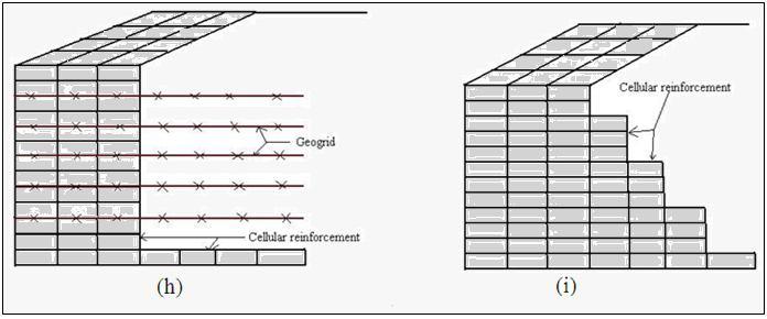
5 Part II Geotextile or geogrid wrap-around-faced mechanically stabilized earth (MSE) walls General Design of geotextile wrap-around-faced wall Wraparound face construction details Part III Gabion walls General Gravity gabion wall design Reinforced soil gabion wall design Feasibility Study on Fly Ash as a Backfill Material Geocell walls
6 Part I Mechanically stabilized segmental reinforced soil retaining wall
7 Basic concepts Soil mechanics Interaction Polymer properties Applications Soft soil applications Reinforced fill applications Unpaved roads Embankments Steep slops Retaining walls (Short term reinforcement strength required) (Long term reinforcement strength required)
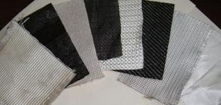
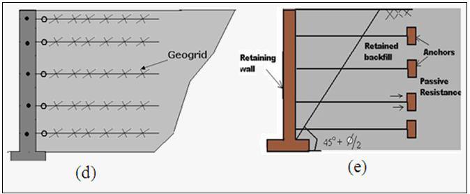
8 Different types of conventional rigid retaining structures made up of masonry and concrete are available to resist the lateral pressures: Gravity retaining walls, Semi-gravity type retaining wall Cantilever retaining walls, Counter fort retaining walls and Bridge and abutment. Anchored Sheet Pile Soil Nailing Braced Excavation

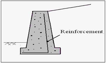
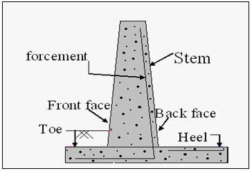
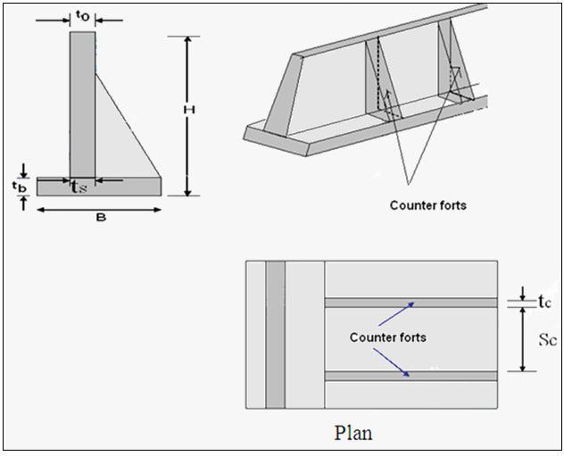
9 Gravity wall Semi-gravity wall Cantilever wall Counter-fort wall


10 Bridge and abutment Anchored Sheet pile Soil Nailing Braced Excavation

 (Lee et al.")
11 Inclusion of reinforcements in soil is not new. It has been used since biblical age. The concept of reinforced earth system is well established. Vidal (1966) (Lee et al., 1973) Components parts and key dimensions of reinforced earth wall
12 The traditional concrete and masonry gravity walls or cantilever retaining walls are almost obsolete due to higher cost of construction. Reinforced soil wall is the best cost effective solution. Metallic strips or geosynthetics can be used as reinforcement. Geosynthetic is an emerging bona-fide engineering construction material around the world. The mild steel degrades due to electro-chemical corrosion whereas, the polymer materials suffer from creep problem causing reduction in the ultimate tensile strength. Therefore, adequate factor of safety should be considered to meet the serviceability limits.
13 There are many disadvantages of using metallic strips in the mechanically stabilized reinforced earth wall, High Cost Long term susceptibility to corrosion. Protective coating can reduce corrosion, but it is uncertain in the field due to ground water or electric current. Sustainability depends on the correct choice of Backfill material ( i.e. gradation, chemical properties etc.) It cannot be used with many indigenous materials. Back fill material cost is about 85% of the total cost of the Reinforced Soil Wall.
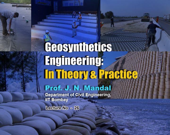
14 Geosynthetic Reinforced Soil Wall System Advantages: Polymer do not corrode Economical Used with many indigenous materials More deformable than the metal reinforcement Long term durability The geosynthetic is flexible Unskilled labour can place it Minimum excavation Good drainage Heavy equipment is not needed
15
16
 walls")

17 Superimposed (Tiered) walls Uneven reinforcement wall (After FHWA-NHI ,2009)
18 - Overall base width is large S M 0.5 H Back-to-back walls (After FHWA-NHI ,2009) - Overlapping of reinforcement L 0 > 0.3 H L R /H = L L /H 0.6
19 Stable feature walls (After FHWA-NHI ,2009)


20 Influence of surcharge for tiered walls (After Simac, 1990)

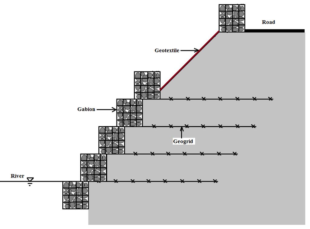
21 Water front structure
22 In the past 40 years, a tremendous number of geosynthetic reinforced soil walls have economically been constructed around the world. The geosynthetics reinforcements are placed horizontally in the retaining wall backfill. Geosynthetics reinforced soil mass are basically gravity structures resisting the earth pressure developed behind the reinforced soil zone. The facia resists the mass of reinforced soil, retained soil and the surcharge loads. Geosynthetics reinforced soil walls are flexible. Therefore, it can tolerate larger settlements and earthquake loading than the conventional retaining walls. The ground improvement can also be avoided.

23 Components of geosynthetic reinforced soil walls
24 Major components of reinforced soil system: Foundation soil It is required to improve the foundation soil by introducing reinforcement layers, geocells, prefabricated vertical band drains or encased stone columns. Check the factor of safety against bearing capacity failure. Reinforced soil The reinforced soil is the combination of soil and the horizontal layers of geotextiles or geogrids. It is preferable to use CEG < 30 mm mol/ kg and molecular weight > 25,000 gm/mol for good quality PET resin. Backfill The backfill soil is located behind the reinforced soil zone.
25 Drainage fill Face drain behind the wall facia. Blanket drain beneath the reinforced soil zone, Back (chimney) drain behind the reinforced soil zone To prevent build up of hydrostatic pressure. The drainage outlet must be connected to the collection pipe. Polymeric geogrids or geotextiles Polymer geogrids and polyester strips, both flexible and stiff, are usually used as horizontal layers. Geocomposite reinforcement or hybrid reinforcement Geotextiles (woven and nonwoven) are also used in wrap-around faced mechanically stabilized earth walls.
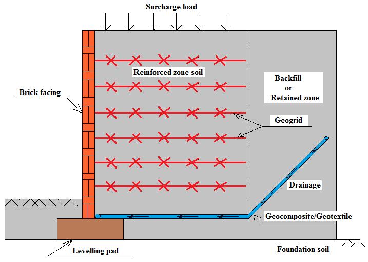
26 Facia The facings have aesthetic views and can be of any shape and colours. Wrap-around facings Segmental precast concrete panels Full-height concrete panels Modular block wall Gabion facings Timber facing Welded wire meshes facing Gunny bag facing Brick facing

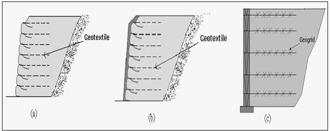
27 Warp- around facing Vertical spacing of reinforcements = 0.3 m m It is required to protect the geotextile against ultraviolet light, degradation, vandalism and damage due to fire. In such case, shotcrete should be applied to the wall facing.
 about 30 cm away from the facing panel.")
28 Segmental precast concrete panels HDPE geogrids are casted into the panels during manufacturing process in the field. The main geogrid is then connected to the HDPE geogrid (bodkin joint) about 30 cm away from the facing panel. The flexible polyester geogrid should not be casted due to high alkalinity in presence of wet concrete.
29 Three types of Precast concrete face panels: Hexagonal shaped panel: 1.5 m height, 1.75 m width and m thick Rectangular panel: 3.81 m long, 0.61 m height and 0.2 m thick T shaped panel: 3.2 m area and 0.16 m thick
30 Bodkin connection details A rigid PVC pipe is used as bodkin. There should not be any slack in the connection.

31 Full-height concrete panels The full height concrete panels are 12.5 cm - 30 cm thick, 240 cm cm wide and 750 cm high. Stiff polyethylene geogrids are casted into the panel similar to segmental precast concrete panels. The minimum compressive strength of concrete at 28 days is Mpa.

32 Modular concrete block wall (MCBW) Length = 200 mm mm Height = 100 mm mm Width = 200 mm m. The weight of dry casting MBW = 15 kg to 50 kg

33 Gabion facing wall The gabion is a kind of basket made up of galvanized mild steel wire mesh and polymer geogrids filled with rocks/stones.


34 Timber facing Welded wire mesh facing Gunny bag facing Brick facing wall

35 DIFFERENT PRECAST CONCRETE MODULAR BLOCKS OR PANEL FACINGS AND CONNECTIONS Modular concrete blocks for segmental retaining walls (After Bathurst and Simac, 1994)


36 Shear Pin Shear Key Leading shear lip Geogrids connected with modular blocks either mechanically or by friction (After Simac et al. 1993)
37 (a) Frictional connection and (b) Mechanical connection

38 Details of frictional connection between geogrid and segmental panel
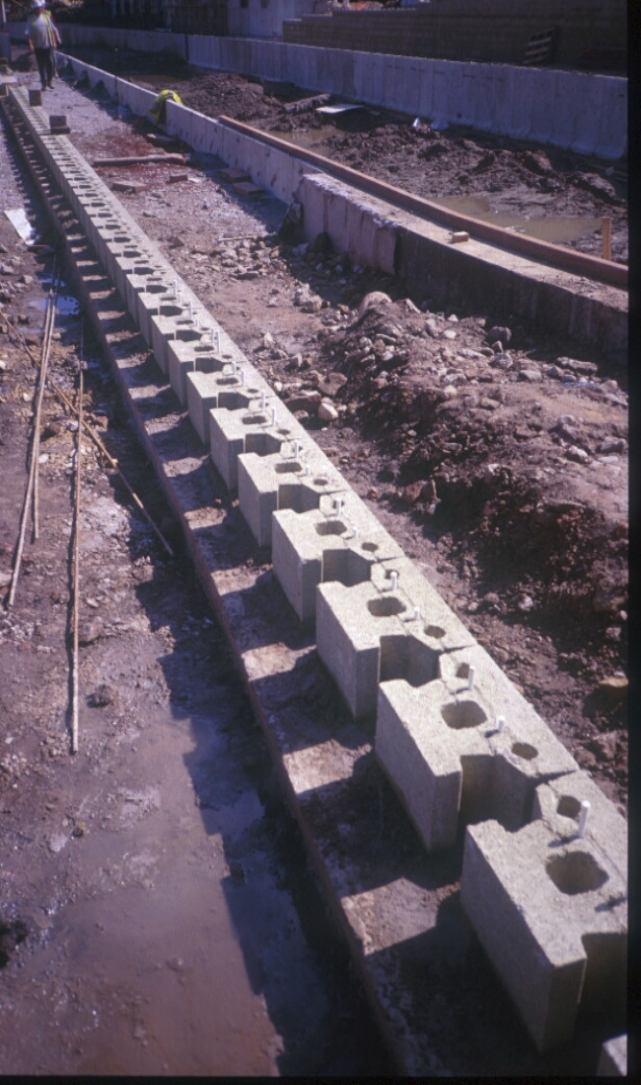
39 Construction Details
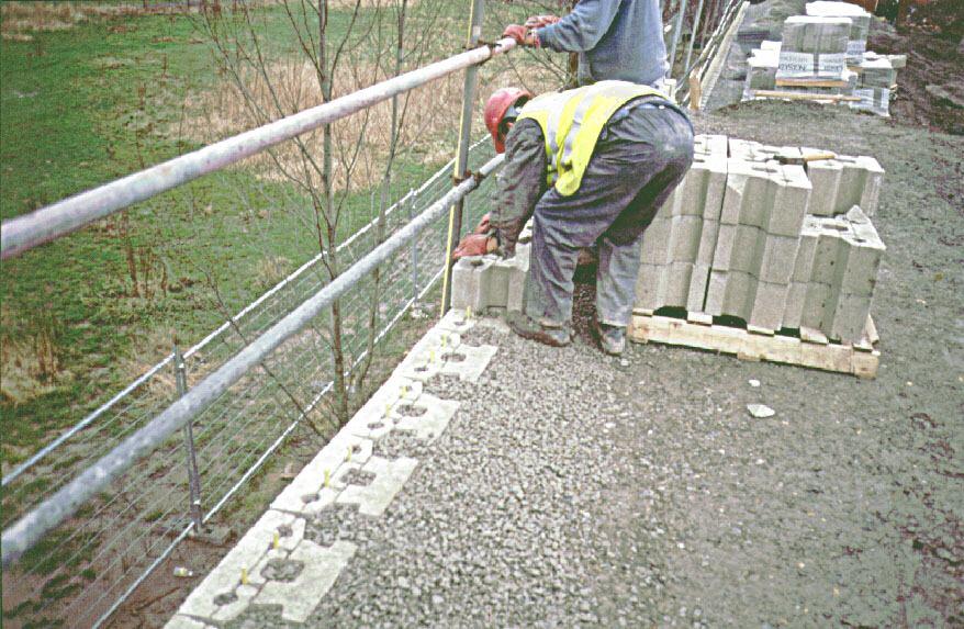
40 Wall Construction

41 General view on Wall During Construction

42 Placing Facing Blocks

43 Wall Ties Fixing False Facing

44 ANALYSIS AND DESIGN PROCEDURES FOR GEOSYNTHETICS REINFORCED SOIL RETAINING WALL Geosynthetic reinforced soil wall with inclined surcharge load
45 Schematic view of segmental reinforced soil retaining wall H M = Mechanical height, H F = Facing height, H D = Design height
46 Step 1: Physical characteristics of mechanically stabilized soil walls. Wall geometry: The height of wall = H, The length of wall = L, Wall face batter angle =, The wall requires a nominal batter of 3 to 10 Slope angle of the soil surface = i, Loading: Surcharge loads: Live load = q L Dead load = q D Total surcharge (q) = q L + q D
47 Type of facing Full-height concrete panels, Wrapped facings, Modular or Segmental concrete blocks. Gabion Vertical spacing of reinforcements (S v ) Wrapping: Maximum spacing (S v ) is 0.5 m to 0.6 m for geotextile (woven and non-woven) or geogrid wrapped face walls. Precast concrete face panels: The spacing of the geogrid reinforcement may be kept from 0.5 m to 1 m. However it is recommended to keep the vertical spacing of reinforcement as 0.6 m m.
48 Modular block: - For the modular concrete block of height 200 mm to 250 mm, the spacing of the reinforcement may be 200 mm, 400 mm, 500 mm, 600 mm, 750mm, 800 mm and 1 m. - For segmental concrete block, if the spacing is more, use secondary reinforcement. Vertical spacing of the reinforcement depends on the strength of the reinforcement, facing connection and types of panels or blocks used for construction.
49 Establish preliminary wall dimensions a) Minimum length of reinforcement (FHWA NHI , 2009) Case Minimum L/H ratio Static loading without or with traffic surcharge 0.7 Sloping backfill surcharge 0.8 Seismic loading 0.8 to 1.1 b) For walls founded on slopes, a minimum horizontal bench of 1.2 m wide should be given in front of wall. Minimum embedment depth should be 0.5 m. Minimum 1 m embedment length is recommended beyond Rankine failure wedge for pullout resistance.
50 Step 2: Evaluate engineering properties of the foundation soil. Detailed soil exploration has to be carried out along the alignment of the reinforced soil wall at every 25 m interval. Evaluate grain size distribution, moisture content, liquid limit, plastic limit, shrinkage limit and plasticity index of soil. Calculate the shear strength and consolidation parameters of foundation soil. Check the location of ground water table.
51 Step 3: Evaluate reinforced fill and retained backfill soil. Check the grain size distribution and plasticity index. Plasticity index should not exceed 6 (AASHTO T-90) Coefficient of uniformity of reinforced fill 2. Organic content should be limited to 5 %. Determine optimum moisture content (OMC), maximum dry density or relative density with the aid of standard proctor test. The minimum compaction of backfill soil should be 90% of maximum proctor density.
52 Internal friction angle (Φ r ) of the soil in reinforced zone can be determined from the drained direct shear test. For retained backfill, the internal friction angle (Φ b ) can be determined by drained triaxial compression test or direct shear test. Generally, angle of internal friction 34º. Coefficient of permeability should be 1 x 10⁻² cm/sec No cohesion should be considered, i.e. fine silts and clay should not be used for reinforced fill. Appropriate drainage system is required at the back, base and front of reinforced soil retaining walls. If the quality of backfill is poor, the adequate drainage can not be achieved (Saidin, 2007).
53 For polyester geosynthetic, ph value of soil should lie between 3 and 9 (Elias and Christopher, 1997) For polyethylene and polypropylene, ph of soil > 3 (AASHTO T ). Minimum aperture size of geogrid > 3.5 times the particle size of the backfill soil (Sarsby, 1985) In many cases, we use the minimum average roll values (MARV) obtained from the manufacturer s certificate. For good design, it is recommended to verify the test results of geosynthetic materials from the third party.
54 Gradation of backfill soil for reinforced soil zone(walls and slopes)(after Koerner et al.1993,gsi/gri) Sieve Size Number Particle Size Percent Passing # mm Notes: FHWA adopts15% passing #200 sieve NCMA adopts 35% passing #200 sieve
55 Creep reduction factor for polymer (FHWA NHI , 2009) Polymer type Creep reduction factors Polyester (PET) 2.5 to 1.6 Polypropylene (PP) 5.0 to 4.0 High Density Polyethlene (HDPE) 5.0 to2.6
56 Please let us hear from you Any question?


57 Prof. J. N. Mandal Department of civil engineering, IIT Bombay, Powai, Mumbai , India. Tel
Earth Retaining System
 Hashemite University Department of Civil Engineering Foundation Engineering Dr. Omar Al-Hattamleh Earth Retaining System Earth slopes and earth retaining structures Used to maintain two different ground
Geo synthetics and Reinforced Soil Structures Prof. K. Rajagopal Department of Civil Engineering Indian Institute of Technology, Madras
 Geo synthetics and Reinforced Soil Structures Prof. K. Rajagopal Department of Civil Engineering Indian Institute of Technology, Madras Lecture - 9 Different Types of Soil Retaining Structures Hello students,
ENGINEERING DIRECTIVE
 Number: E-95-001 Date: 2/2/95 ENGINEERING DIRECTIVE Ross B. Dindio (Signature on Original) CHIEF ENGINEER The purpose of this engineering directive is to formally notify ALL Department engineering personnel
This paper describes the salient features of a
 Geogrid Reinforced Soil Walls with Welded Wire Mesh Facing to Retain the Approaches to a Flyover This paper describes the salient features of a project wherein geogrid reinforced soil walls with a welded
Geoguide 6 The New Guide to Reinforced Fill Structure and Slope Design in Hong Kong
 Geoguide 6 The New Guide to Reinforced Fill Structure and Slope Design in Hong Kong Geotechnical Engineering Office Civil Engineering Department The Government of the Hong Kong Special Administrative Region
SECTION SPECIFICATION FOR STONEBRIDGE RETAINING WALL SYSTEM
 SECTION 32 32 23 SPECIFICATION FOR STONEBRIDGE RETAINING WALL SYSTEM PART 1: GENERAL 1.01 Scope Work includes furnishing all materials, labor, equipment, and supervision to install a Stonebridge segmental
Earth Retaining Structures and Systems Submittal Checklist. Part One: Materials and Material Properties
 Earth Retaining Structures and Systems Submittal Checklist Part One: Materials and Material Properties Provide a sample of the reinforcement material and material specifications describing the material
MECHANICALLY STABILIZED EARTH (MSE) WALL SYSTEMS
 WALL SYSTEMS") DRAINAGE SOLUTIONS SINCE 1908 MECHANICALLY STABILIZED EARTH (MSE) WALL SYSTEMS PERMANENT AND TEMPORARY ENGINEERED WALL SOLUTIONS ECONOMICAL DURABLE VERSATILE ARMTEC.COM MSE RETAINING WALLS Armtec Mechanically
DRAINAGE SOLUTIONS SINCE 1908 MECHANICALLY STABILIZED EARTH (MSE) WALL SYSTEMS PERMANENT AND TEMPORARY ENGINEERED WALL SOLUTIONS ECONOMICAL DURABLE VERSATILE ARMTEC.COM MSE RETAINING WALLS Armtec Mechanically
MagnumStone Specifications Gravity
 MagnumStone Specifications Gravity SPECIFICATION FOR MAGNUMSTONE GRAVITY MECHANICALLY STABILIZED EARTH SYSTEM PART 1: GENERAL.01Description The work consists of supplying and installing all aspects of
ICBO Evaluation Service, Inc Workman Mill Road, Whittier, California
 ER-5435 Reissued May 1, 2002 ICBO Evaluation Service, Inc. 5360 Workman Mill Road, Whittier, California 90601 www.icboes.org Filing Category: DESIGN Masonry MESA RETAINING BLOCK WALL SYSTEM TENSAR EARTH
SPECIFICATIONS FOR PRECAST MODULAR BLOCK RETAINING WALL SYSTEM (revised 5/8/7)
") Page 1 of 7 STONE STRONG SYSTEMS SPECIFICATIONS FOR PRECAST MODULAR BLOCK RETAINING WALL SYSTEM (revised 5/8/7) PART 1: GENERAL 1.01 Description A. Work includes furnishing and installing precast modular
Page 1 of 7 STONE STRONG SYSTEMS SPECIFICATIONS FOR PRECAST MODULAR BLOCK RETAINING WALL SYSTEM (revised 5/8/7) PART 1: GENERAL 1.01 Description A. Work includes furnishing and installing precast modular
SPECIFICATIONS FOR PRECAST MODULAR BLOCK RETAINING WALL SYSTEM (revised 9/17/18)
") Page 1 of 8 STONE STRONG SYSTEMS SPECIFICATIONS FOR PRECAST MODULAR BLOCK RETAINING WALL SYSTEM (revised ) PART 1: GENERAL 1.01 Description A. Work includes furnishing and installing precast modular blocks
Page 1 of 8 STONE STRONG SYSTEMS SPECIFICATIONS FOR PRECAST MODULAR BLOCK RETAINING WALL SYSTEM (revised ) PART 1: GENERAL 1.01 Description A. Work includes furnishing and installing precast modular blocks
Design and Construction Aids in Advanced Geosynthetics Engineering. J. N. Mandal
 Draft copy Design and Construction Aids in Advanced Geosynthetics Engineering J. N. Mandal About this book: This book is the source of current state-of-the-art knowledge and practice which he has acquired
GEOSYNTHETICS ENGINEERING: IN THEORY AND PRACTICE
 GEOSYNTHETICS ENGINEERING: IN THEORY AND PRACTICE Prof. J. N. Mandal Department of civil engineering, IIT Bombay, Powai, Mumbai 400076, India. Tel.022-25767328 email: cejnm@civil.iitb.ac.in Module - 4
CHAPTER 11: WALLS.
 CHAPTER 11: WALLS MODULAR BLOCK WALL (DRY CAST) Rather than being pre-approved as systems, the components of Modular block walls (dry cast) are pre-approved separately. The approved MBW components are
GEOSYTHETIC SLOPE SPEC-V0704rev.doc STANDARD SPECIAL PROVISION FOR GEOSYNTHETIC REINFORCED SLOPE CONSTRUCTION
 GEOSYTHETIC SLOPE SPEC-V0704rev.doc STANDARD SPECIAL PROVISION FOR GEOSYNTHETIC REINFORCED SLOPE CONSTRUCTION I. DESCRIPTION - This work consists of furnishing the required materials and construction of
CYPRESS Stone Geogrid Reinforced Retaining Wall Installation Specification SECTION CONCRETE SEGMENTAL RETAINING WALL PART 1 GENERAL
 CYPRESS Stone Geogrid Reinforced Retaining Wall Installation Specification SECTION 02832- CONCRETE SEGMENTAL RETAINING WALL PART 1 GENERAL 1.01 Description A) The work covered by this section includes
DESIGNING AND CONSTRUCTION OF T-WALL RETAINING WALL SYSTEM
 Istanbul Bridge Conference August 11-13, 2014 Istanbul, Turkey DESIGNING AND CONSTRUCTION OF T-WALL RETAINING WALL SYSTEM T. C. NEEL and K.BOZKURT ABSTRACT This work shall consist of the design, manufacture
Behavior of Geosynthetic-Reinforced Earth
 Behavior of Geosynthetic-Reinforced Earth Presented by Kousik Deb Assistant Professor Department of Civil Engineering IIT Kharagpur Problems for Foundations on Weak Soils Experience excessive settlement
SPECIFICATION FOR MAGNUMSTONE GEOGRID REINFORCED Mechanically Stabilized Earth (MSE) SYSTEM
 SYSTEM") MagnumStone Specifications Geogrid Reinforced SPECIFICATION FOR MAGNUMSTONE GEOGRID REINFORCED Mechanically Stabilized Earth (MSE) SYSTEM PART 1: GENERAL 1.01 Description The work consists of supplying
MagnumStone Specifications Geogrid Reinforced SPECIFICATION FOR MAGNUMSTONE GEOGRID REINFORCED Mechanically Stabilized Earth (MSE) SYSTEM PART 1: GENERAL 1.01 Description The work consists of supplying
EFFECT OF REINFORCEMENT, BACKFILL AND SURCHARGE ON THE PERFORMANCE OF REINFORCED EARTH RETAINING WALL
 EFFECT OF REINFORCEMENT, BACKFILL AND SURCHARGE ON THE PERFORMANCE OF REINFORCED EARTH RETAINING WALL Anand M. Hulagabali 1, C. H. Solanki 1, G. R. Dodagoudar 2 and M. P. Shettar 3 1 Department of Applied
SECTION MECHANICALLY STABILIZED EARTH RETAINING WALLS
 SECTION 13100 MECHANICALLY STABILIZED EARTH RETAINING WALLS PART 1 -- GENERAL 1.01 THE REQUIREMENT A. Includes all labor, material, equipment, testing and submittals required to design and complete construction
RETAINING WALLS CHAPTER 13. Omitted parts: Section
 RETAINING WALLS CHAPTER 13 Omitted parts: Section 13.9 13.15-13.17 INTRODUCTION Retaining walls are structures that restrain soil or other materials at locations having an abrupt change in elevation. In
GEOSYNTHETICS ENGINEERING: IN THEORY AND PRACTICE
 GEOSYNTHETICS ENGINEERING: IN THEORY AND PRACTICE Prof. J. N. Mandal Department of civil engineering, IIT Bombay, Powai, Mumbai 400076, India. Tel.022-25767328 email: cejnm@civil.iitb.ac.in Module-5 LECTURE-
Section ( ) SPECIFICATION FOR SEGMENTAL CONCRETE UNIT RETAINING WALL
 SPECIFICATION FOR SEGMENTAL CONCRETE UNIT RETAINING WALL") Section 02834 (32 32 23) SPECIFICATION FOR SEGMENTAL CONCRETE UNIT RETAINING WALL PART 1: GENERAL 1.01 Description A. Work shall consist of furnishing and construction of a County Materials Retaining Wall
Section 02834 (32 32 23) SPECIFICATION FOR SEGMENTAL CONCRETE UNIT RETAINING WALL PART 1: GENERAL 1.01 Description A. Work shall consist of furnishing and construction of a County Materials Retaining Wall
NPTEL Course. GROUND IMPROVEMENT Factors affecting the behaviour and performance of reinforced soil
 Lecture 27 NPTEL Course GROUND IMPROVEMENT Factors affecting the behaviour and performance of reinforced soil Prof. G L Sivakumar Babu Department of Civil Engineering Indian Institute of Science Bangalore
Best Practices for Design and Construction of MSE Walls
 Best Practices for Design and Construction Robert A. Gladstone, P.E. Executive Director Association for Mechanically Stabilized Earth Geotechnical Consultant Workshop Ohio Department of Transportation
SPECIFICATION FOR CORNERSTONE GEOGRID REINFORCED SEGMENTAL RETAINING WALL SYSTEM
 CornerStone Specifications Geogrid Reinforced SPECIFICATION FOR CORNERSTONE GEOGRID REINFORCED SEGMENTAL RETAINING WALL SYSTEM PART 1: GENERAL 1.01 Description The work consists of supplying and installing
Wmega Retaining Wall Specification
 Wmega Retaining Wall Specification 1. General 1.01 Description A. This work shall consist of furnishing and installing an Ωmega Segmental Retaining Wall System in accordance with these specifications and
Static Response of Reinforced Soil Retaining Walls with Modular Block Facing
 Static Response of Reinforced Soil Retaining Walls with Modular Block Facing Morteza Sabet 1, Amir M. Halabian 2, Kazem Barkhordari 3 1 Graduate Student, Department of Civil Engineering, Yazd University
SECTION CONCRETE SEGMENTAL RETAINING WALL SYSTEM
 Anchor [beveled-face and straight-face products] SECTION 32 32 23 CONCRETE SEGMENTAL RETAINING WALL SYSTEM PART 1 GENERAL 1.01 SECTION INCLUDES A. Concrete segmental retaining wall units B. Geosynthetic
SECTION ( ) MODULAR CONCRETE RETAINING WALL SYSTEM WEATHERED MULTI SHAPE 8 (203mm) HIGH UNITS
 MODULAR CONCRETE RETAINING WALL SYSTEM WEATHERED MULTI SHAPE 8 (203mm) HIGH UNITS") SECTION 02834 (32 32 23) MODULAR CONCRETE RETAINING WALL SYSTEM WEATHERED MULTI SHAPE 8 (203mm) HIGH UNITS 1.0 GENERAL 1.1 Description The work includes furnishing and constructing a 8 inch high multi-shape
SECTION 02834 (32 32 23) MODULAR CONCRETE RETAINING WALL SYSTEM WEATHERED MULTI SHAPE 8 (203mm) HIGH UNITS 1.0 GENERAL 1.1 Description The work includes furnishing and constructing a 8 inch high multi-shape
SECTION CONCRETE SEGMENTAL RETAINING WALL SYSTEM
 SECTION 02832 CONCRETE SEGMENTAL RETAINING WALL SYSTEM PART 1.: GENERAL 1.01 WORK INCLUDED A. This section includes the following: The Specifications on furnishing the design, materials and labor required
Chapter 18 EARTH RETAINING STRUCTURES
 Chapter 18 EARTH RETAINING STRUCTURES Final SCDOT GEOTECHNICAL DESIGN MANUAL June 2010 SCDOT Geotechnical Design Manual Earth Retaining Structures Table of Contents Section Page 18.1 Introduction...18-1
SECTION SPECIFICATION FOR MECHANICALLY STABILIZED EARTH TWO STAGE WALL SYSTEM
 SECTION 02830 SPECIFICATION FOR MECHANICALLY STABILIZED EARTH TWO STAGE WALL SYSTEM ## THIS SECTION IS WRITTEN IN CSI 3-PART FORMAT AND IN CSI PAGE FORMAT. NOTES TO THE SPECIFIER, SUCH AS THIS, ARE INDICATED
Module 4 Reinforced Soil Systems. Introduction To Geosynthetics In Transportation. Prepared by. For the Local Technical Assistance Program.
 Module 4 Reinforced Soil Systems Introduction To Geosynthetics In Transportation Prepared by July 2007 For the Local Technical Assistance Program The Geosynthetic Materials Association (GMA) represents
ICC-ES Evaluation Report Issued July 1, 2011 This report is subject to renewal in one year.
 ICC-ES Evaluation Report ESR-1959 Issued July 1, 2011 This report is subject to renewal in one year. www.icc-es.org (800) 423-6587 (562) 699-0543 A Subsidiary of the International Code Council DIVISION:
Section (02830) MODULAR CONCRETE RETAINING WALL
 MODULAR CONCRETE RETAINING WALL") Section 323223 (02830) MODULAR CONCRETE RETAINING WALL PART 1: GENERAL 1.01 Description A. Work shall consist of furnishing and constructing a VERDURA Retaining Wall System (or approved equal) in accordance
Section 323223 (02830) MODULAR CONCRETE RETAINING WALL PART 1: GENERAL 1.01 Description A. Work shall consist of furnishing and constructing a VERDURA Retaining Wall System (or approved equal) in accordance
Geotechnical Analysis of Stepped Gravity Walls
 Geotechnical Analysis of Stepped Gravity Walls Baleshwar Singh 1 * and Birjukumar Mistri 2 1 Associate Professor, Civil Engineering Department, IIT Guwahati, India 2 Former Post-Graduate Student, Civil
INDOT Wall System Approval Criteria and Design Review
 INDOT Wall System Approval Criteria and Design Review Yuhui Hu, P.E. Office of Geotechnical Services, INDOT March 12, 2014 Slide 1 Outline Types of earth retaining structures Types of Mechanically Stabilized
DIVISION: EXTERIOR IMPROVEMENTS SECTION: SEGMENTAL RETAINING WALLS REPORT HOLDER: ANCHOR WALL SYSTEMS EVALUATION SUBJECT:
 0 Most Widely Accepted and Trusted ICC ES Evaluation Report ICC ES 000 (800) 423 6587 (562) 699 0543 www.icc es.org ESR 1959 Reissued 07/2018 This report is subject to renewal 07/2019. DIVISION: 32 00
CONCRETE SEGMENTAL RETAINING WALLS
 32 32 23.13 CONCRETE SEGMENTAL RETAINING WALLS 1.00 GENERAL 1.01 DESCRIPTION A. The work shall consist of furnishing and installing concrete segmental retaining wall (CSRW) units to the lines, grades and
GEOGRIDS IN WALLS AND SLOPES. Corbet S.P 1 & Diaz M 2. AECOM Ltd Chelmsford, CM1 1HT. ( ) 2
 2") GEOGRIDS IN WALLS AND SLOPES Corbet S.P 1 & Diaz M 2 1 AECOM Ltd Chelmsford, CM1 1HT. (e-mail: steve.corbet@aecom.com ) 2 AECOM Ltd Chelmsford, CM1 1HT. (e-mail: maria.espinoza@aecom.com ) INTRODUCTION
GEOGRIDS IN WALLS AND SLOPES Corbet S.P 1 & Diaz M 2 1 AECOM Ltd Chelmsford, CM1 1HT. (e-mail: steve.corbet@aecom.com ) 2 AECOM Ltd Chelmsford, CM1 1HT. (e-mail: maria.espinoza@aecom.com ) INTRODUCTION
Section ( ) MODULAR CONCRETE RETAINING WALL
 MODULAR CONCRETE RETAINING WALL") Section 02834 (32 32 23) MODULAR CONCRETE RETAINING WALL PART 1: GENERAL 1.01 Description A. Work shall consist of furnishing and construction of a KEYSTONE 133Elite Unit Retaining Wall System or equal
Section 02834 (32 32 23) MODULAR CONCRETE RETAINING WALL PART 1: GENERAL 1.01 Description A. Work shall consist of furnishing and construction of a KEYSTONE 133Elite Unit Retaining Wall System or equal
MODULAR CONCRETE RETAINING WALL
 MODULAR CONCRETE RETAINING WALL PART 1: GENERAL 1.01 Description A. Work shall consist of furnishing and construction of a KEYSTONE Retaining Wall System or equal in accordance with these specifications
INSPECTION GUIDE FOR SEGMENTAL RETAINING WALLS TEK 18-11B
 An information series from the national authority on concrete masonry technology INSPECTION GUIDE FOR SEGMENTAL RETAINING WALLS TEK 18-11B Quality Assurance and Testing (2012) INTRODUCTION Segmental retaining
STATE OF OHIO DEPARTMENT OF TRANSPORTATION SUPPLEMENTAL SPECIFICATION 863 REINFORCED SOIL SLOPES. October 19, 2012
 STATE OF OHIO DEPARTMENT OF TRANSPORTATION 863.01 Description 863.02 Materials 863.03 Construction 863.04 Method of Measurement 863.05 Basis of Payment SUPPLEMENTAL SPECIFICATION 863 REINFORCED SOIL SLOPES
APPLICABILITY OF COMPOSITE SOIL REINFORCEMENT SYSTEM WALLS FOR HIGH RETAINING STRUCTURES.
 APPLICABILITY OF COMPOSITE SOIL REINFORCEMENT SYSTEM WALLS FOR HIGH RETAINING STRUCTURES. Minimol Korulla, General Manager, Maccaferri Environmental Solutions Pvt. Ltd., India. minikorulla@maccaferri-india.com
Celtik Pro TM Wall Spec
 Celtik Pro TM Wall Spec Section 32 32 23 MODULAR CONCRETE RETAINING WALL SYSTEM NOTE: This specification covers the installation of both conventional gravity and reinforced soil Segmental Retaining Wall
Earth Retaining Walls CIVL455 CHAPTER I: INTRODUCTION
 Earth Retaining Walls CIVL455 CHAPTER I: INTRODUCTION Earth retaining structures are designed to overcome significant variation in ground levels to provide either a sloping or flat ground on the retained
GEOSYNTHETICS ENGINEERING: IN THEORY AND PRACTICE
 GEOSYNTHETICS ENGINEERING: IN THEORY AND PRACTICE Prof. J. N. Mandal Department of civil engineering, IIT Bombay, Powai, Mumbai 400076, India. Tel.022-25767328 email: cejnm@civil.iitb.ac.in Module - 9
GEOSYNTHETICS ENGINEERING: IN THEORY AND PRACTICE
 GEOSYNTHETICS ENGINEERING: IN THEORY AND PRACTICE Prof. J. N. Mandal Department of civil engineering, IIT Bombay, Powai, Mumbai 400076, India. Tel.022-25767328 email: cejnm@civil.iitb.ac.in Module - 9
Bureau of Materials Materials Approval Procedures
 Bureau of Materials Materials Approval Procedures MAP Number: 116-15 Effective Date: April 1, 2015 Approved By: Eileen Sheehy PROCEDURE FOR APPROVAL OF MECHANICALLY STABILIZED EARTH (MSE) RETAINING WALL
GEOSYNTHETICS ENGINEERING: IN THEORY AND PRACTICE
 GEOSYNTHETICS ENGINEERING: IN THEORY AND PRACTICE Prof. J. N. Mandal Department of civil engineering, IIT Bombay, Powai, Mumbai 400076, India. Tel.022-25767328 email: cejnm@civil.iitb.ac.in Module-5 LECTURE-
DIVISION: EXTERIOR IMPROVEMENTS SECTION: RETAINING WALLS SECTION: SEGMENTAL RETAINING WALLS REPORT HOLDER:
 0 Most Widely Accepted and Trusted ICC-ES Evaluation Report ICC-ES 000 (800) 423-6587 (562) 699-0543 www.icc-es.org ESR-1784 Issued 02/2018 This report is subject to renewal 02/2019. DIVISION: 32 00 00
SECTION SEGMENTAL CONCRETE UNIT MASONRY RETAINING WALL MAXIMUM HEIGHT OF 5-0 HIGH
 DIVISION 32 EXTERIOR IMPROVEMENTS SECTION 32 32 23.13 SEGMENTAL CONCRETE UNIT MASONRY RETAINING WALL MAXIMUM HEIGHT OF 5-0 HIGH PART 1: GENERAL 1.01 Scope of Standards A. This standard provides general
SECTION MECHANICALLY STABILIZED EARTH 1.01 SUMMARY
 SECTION 028300 PART 1 GENERAL 1.01 SUMMARY A. Section includes Basis of Design Mechanically Stabilized Earth System: SierraScape Mechanically Stabilized Earth (MSE) retaining wall system having high density
DESIGN CONSIDERATIONS FOR NSWS NATURAL STONE RETAINING AND FREE-STANDING WALL SYSTEMS
 DESIGN CONSIDERATIONS FOR NSWS NATURAL STONE RETAINING AND FREE-STANDING WALL SYSTEMS Natural Stone Wall Solutions, Inc (NSWS ) 2352 Main Street, Suite 103 Concord, MA 01742 (978) 461-1777 Concept and
Section ( ) KEYSTONE CONCRETE RETAINING WALL
 KEYSTONE CONCRETE RETAINING WALL") Section 02834 (32 32 23) KEYSTONE CONCRETE RETAINING WALL PART 1: GENERAL 1.01 Description A. Work shall consist of designing, furnishing and construction of a KEYSTONE Compac Unit Retaining Wall System
Section 02834 (32 32 23) KEYSTONE CONCRETE RETAINING WALL PART 1: GENERAL 1.01 Description A. Work shall consist of designing, furnishing and construction of a KEYSTONE Compac Unit Retaining Wall System
Geosynthetics and Reinforced Soil Structures
 Geosynthetics and Reinforced Soil Structures Testing Requirements for Design of Reinforced Soil Walls Prof K. Rajagopal Department of Civil Engineering g IIT Madras, Chennai e-mail: gopalkr@iitm.ac.inac
Subject Index ASTM D , 28, 57, 63, 67, 83-86, 98, 111, ASTM D , 57
 STP952-EB/JUI. 1987 Subject Index Abrasion resistance, 120, 168-169 Apparent opening size, 7, 21, 29-30, 172-173 defined, 30 versus equivalent opening size, 9-12 Apparent slope height, 96 Approved list,
SECTION CONCRETE SEGMENTAL RETAINING WALL SYSTEM
 SECTION 32 32 23 CONCRETE SEGMENTAL RETAINING WALL SYSTEM PART 1 - GENERAL 1.01 DESCRIPTION A. Work consists of furnishing and construction of an Anchor Diamond Pro Retaining Wall System in accordance
CONCRETE SEGMENTAL RETAINING WALL SYSTEM
 CONCRETE SEGMENTAL RETAINING WALL SYSTEM PART 1: GENERAL SPECIFICATIONS 1.01 Work Included A. Work shall consist of furnishing and constructing a Rockwood Classic 8, Classic 6 and Legend unit segmental
SPECIFICATION FOR REINFORCED SOIL WALL
 SPECIFICATION FOR REINFORCED SOIL WALL 1.0 EXTENT OF WORK The work shall consist of Reinforced Soil walls built in accordance with this specification and in conformity with the lines, levels and details
STATE OF OHIO DEPARTMENT OF TRANSPORTATION SUPPLEMENTAL SPECIFICATION 867 TEMPORARY WIRE FACED MECHANICALLY STABILIZED EARTH WALL.
 STATE OF OHIO DEPARTMENT OF TRANSPORTATION SUPPLEMENTAL SPECIFICATION 867 TEMPORARY WIRE FACED MECHANICALLY STABILIZED EARTH WALL April 15, 2016 867.01 Description 867.02 Definitions 867.03 Materials 867.04
Description. This work shall consist of furnishing materials and placement of modular block wall constructed in accordance with
 MODULAR CONCRETE BLOCK RETAINING WALL WITH GROUND REINFORCING The Standard Specifications are revised as follows: 732-R-310r 1of 11 Rev. 12-03-03 SECTION 105, AFTER LINE 48, INSERT AS FOLLOWS: When constructing
Geosynthetics and Reinforced Soil Structures Prof. K. Rajagopal Department of Civil Engineering Indian Institute of Technology, Madras
 Geosynthetics and Reinforced Soil Structures Prof. K. Rajagopal Department of Civil Engineering Indian Institute of Technology, Madras Lecture - 21 Geosynthetic Reinforced Soil Embankments I Good morning
GRAVITY SEGMENTAL RETAINING WALL
 [NOTE TO SPECIFICATION WRITER: This guide specification for the use of gravity segmental retaining walls (with no soil reinforcement) was developed based on the use of an aggregate or unreinforced concrete
SECTION Segmental Concrete Unit Masonry Retaining Wall Height Over 5-0 High
 PART 1: GENERAL 1.0 0 Scope of Standards A. This standard provides general guidance concerning the specific preferences of the Texas State University for a Segmental Retaining Wall up to 5-0 high. B. Texas
SRW SPECIFICATIONS SRW HISTORY ARTICLE SERIES NCMA SPECIFICATIONS
 SRW HISTORY ARTICLE SERIES SRW SPECIFICATIONS This is the fifth article in a series of ten articles on the history of segmental retaining walls developed under a grant from the NCMA Education and Research
SIERRASCAPE SYSTEM DESIGN GUIDE
 TTN:SC1 Tensar Technical Note SIERRASCAPE SYSTEM DESIGN GUIDE Facing Stability Considerations 2004 Tensar Earth Technologies, Inc. 6/30/04 TABLE OF CONTENTS EXECUTIVE SUMMARY LIST OF FIGURES Page iii iv
Building Construction
 Building Construction Shallow Foundations Module-III Introduction The foundation can be classified broadly into two types: Shallow foundations Deep foundations Shallow foundations Shallow Foundations When
RETAINING WALL SYSTEM. ViaWall. ViaWall A. ViaWall B. ViaBlock
 RETAINING WALL SYSTEM ViaWall ViaWall A ViaWall B ViaBlock Table of contents Introduction page 1 ViaWall type A Elements of the system 1. Reinforced concrete panel 2. Reinforcing meshes 3. U-bolts Additional
SECTION CONCRETE SEGMENTAL RETAINING WALL SYSTEM
 Anchor Vertica SECTION 02832 CONCRETE SEGMENTAL RETAINING WALL SYSTEM PART 1 - GENERAL 1.01 SECTION INCLUDES A. Retaining wall system constructed of concrete segmental retaining wall units. B. Geosynthetic
TENAX TT MONO-ORIENTED HDPE GEOGRID
 TENAX TT MONO-ORIENTED HDPE GEOGRID Rev June 2013 Sales orders / enquiries - Email sales@gtsl.co.nz - Phone 0800 436 832 - www.geotechsystems.co.nz Page 2 of 39 Rev June 2013 Sales orders / enquiries -
Wall Modular Block Mechanically Stabilized Earth, Item S.
 Wall Modular Block Mechanically Stabilized Earth, Item 532.0300.S. A Description (1) This special provision describes designing, furnishing materials and erecting a permanent earth retention system in
DETERMINATION OF THE LONG TERM PROPERTIES FOR MIRAFI PET-SERIES REINFORCEMENT GEOTEXTILES BY GRI-GT7 AND NCMA GUIDELINES
 DETERMINATION OF THE LONG TERM PROPERTIES FOR MIRAFI PET-SERIES REINFORCEMENT GEOTEXTILES BY GRI-GT7 AND NCMA GUIDELINES Prepared by: TenCate TM Geosynthetics North America 365 South Holland Drive Pendergrass,
SPECIFICATION FOR GALVANIZED STEEL WIRE FORMED, STONE FILLED MECHANICALLY STABILIZED EARTH RETANING WALL
 SECTION 02830 SPECIFICATION FOR GALVANIZED STEEL WIRE FORMED, STONE FILLED MECHANICALLY STABILIZED EARTH RETANING WALL PART 1 GENERAL 1.01 SUMMARY A. Section includes Mechanically Stabilized Earth (MSE)
DIVISION: EXTERIOR IMPROVEMENTS SECTION: RETAINING WALLS SECTION: SEGMENTAL RETAINING WALLS REPORT HOLDER:
 0 Most Widely Accepted and Trusted ICC ES Evaluation Report ICC ES 000 (800) 423 6587 (562) 699 0543 www.icc es.org ESR 3073 Reissued 07/2017 This report is subject to renewal 07/2018. DIVISION: 32 00
ARES Retaining Wall Systems >
 SYSTEM OVERVIEW Tensar Geogrids When reliability and speed of construction are concerns, ARES Walls offer unmatched advantages. The ARES Systems owe their strength and durability to Uniaxial (UX) Geogrids,
DETERMINATION OF THE LONG-TERM PROPERTIES FOR MIRAGRID XT GEOGRIDS
 DETERMINATION OF THE LONG-TERM PROPERTIES FOR MIRAGRID XT GEOGRIDS Prepared by: TenCate Geosynthetics Americas 365 South Holland Drive Pendergrass, GA 30567 Tel 706 693 2226 Fax 706 693 4400 www.tencate.com
SECTION CONCRETE SEGMENTAL RETAINING WALL SYSTEM BIG BLOCK / WETCAST
 LondonBoulder Retaining Wall Units SECTION 32 32 23 CONCRETE SEGMENTAL RETAINING WALL SYSTEM BIG BLOCK / WETCAST PART 1 - GENERAL 1.01 SECTION INCLUDES A. Retaining wall system constructed of wet-cast
Originally Issued: 09/30/2011 Revised: 09/15/2017 Valid Through: 09/30/ Design:
 ALLAN BLOCK CORPORATION ALLAN BLOCK RETAINING WALL SYSTEMS CSI Section: 32 32 00 Retaining Walls 1.0 RECOGNITION Allan Block Retaining Wall System recognized in this report has been evaluated for use as
Evaluation of Geosynthetic Forces in GRSRW under Dynamic Condition
 Evaluation of Geosynthetic Forces in GRSRW under Dynamic Condition Kooshyar Passbakhsh, Maryam Yazdi Abstract Geosynthetics have proved to be suitable for reinforced soil retaining walls. Based on the
IGC. 50 th INDIAN GEOTECHNICAL CONFERENCE BEHAVIOUR OF GEOTEXTILE ENCASED QUARRY WASTE COLUMN SUBJECTED TO SHEAR LOADING IN SOFT CLAY
 th th INDIAN GEOTECHNICAL CONFERENCE 17 th 19 th DECEMBER, Pune, Maharashtra, India Venue: College of Engineering (Estd. 184), Pune, India BEHAVIOUR OF GEOTEXTILE ENCASED QUARRY WASTE COLUMN SUBJECTED
Retaining Wall Installation Specifications
 U-Cara Segmental Retaining Wall Retaining Wall Installation Specifications Prepared by Risi Stone Systems Used by permission. BOSTON BUFFALO CHICAGO CLEVELAND DETROIT NEW YORK TORONTO FOREWORD This outline
DESIGN OF RETAINING WALLS
 DESIGN OF RETAINING WALLS Dr. Izni Syahrizal bin Ibrahim Faculty of Civil Engineering Universiti Teknologi Malaysia Email: iznisyahrizal@utm.my Introduction Retaining wall is used to retain earth or other
SPECIFICATION FOR SEGMENTAL RETAINING WALLS Mesa Retaining Wall System
 SECTION 02830 SPECIFICATION FOR SEGMENTAL RETAINING WALLS Mesa Retaining Wall System ## THIS SECTION IS WRITTEN IN CSI 3-PART FORMAT AND IN CSI PAGE FORMAT. NOTES TO THE SPECIFIER, SUCH AS THIS, ARE INDICATED
MECHANICALLY STABILIZED EARTH (MSE) WALLS
 WALLS") Supplemental Technical Specification for MECHANICALLY STABILIZED EARTH (MSE) WALLS SCDOT Designation: SC-M-713 (01/19) 1.0 RELEVANCE 1.1 This Supplemental Technical Specification (STS) replaces Section
Supplemental Technical Specification for MECHANICALLY STABILIZED EARTH (MSE) WALLS SCDOT Designation: SC-M-713 (01/19) 1.0 RELEVANCE 1.1 This Supplemental Technical Specification (STS) replaces Section
5-20 FOUNDATION REPORT/GEOTECHNICAL DESIGN
 5-20 FOUNDATION REPORT/GEOTECHNICAL DESIGN REPORT CHECKLIST FOR EARTH RETAINING SYSTEMS Introduction This checklist was developed to assist the geotechnical project professionals in preparing the Foundation
Specification Guidelines: Allan Block Modular Retaining Wall Systems
 Specification Guidelines: Allan Block Modular Retaining Wall Systems The following specifications provide Allan Block Corporation's typical requirements and recommendations. At the engineer of record's
Bearing Capacity of Footing on Reinforced Flyash Slope
 RESEARCH ARTICLE OPEN ACCESS Bearing Capacity of Footing on Reinforced Flyash Slope Dr. A.I. Dhatrak 1, Nidhi Gandhi 2 Associate Professor, Department of Civil Engineering, Government College of Engineering,
Stability of a Mechanically Stabilized Earth Wall
 Stability of a Mechanically Stabilized Earth Wall GEO-SLOPE International Ltd. www.geo-slope.com 1400, 633-6th Ave SW, Calgary, AB, Canada T2P 2Y5 Main: +1 403 269 2002 Fax: +1 403 266 4851 Introduction
GEOSYNTHETICS ENGINEERING: IN THEORY AND PRACTICE
 GEOSYNTHETICS ENGINEERING: IN THEORY AND PRACTICE Prof. J. N. Mandal Department of Civil Engineering, IIT Bombay, Powai, Mumbai 400076, India. Tel.022-25767328 email: cejnm@civil.iitb.ac.in Module-13 LECTURE-
Geogrid Soil Reinforcement
 Supplemental Technical Specification for Geogrid Soil Reinforcement SCDOT Designation: SC-M-203-2 (4/16) 1.0 DESCRIPTION The requirements of this specification consist of furnishing all necessary submittals