Test Report No.: Page 2 of 35
|
|
|
- Elfrieda Maxwell
- 5 years ago
- Views:
Transcription
1
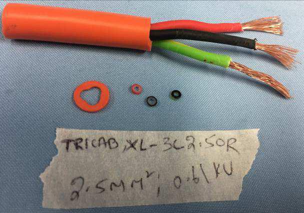
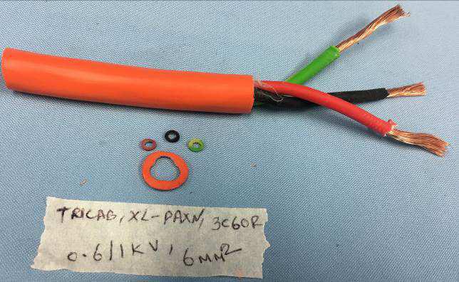
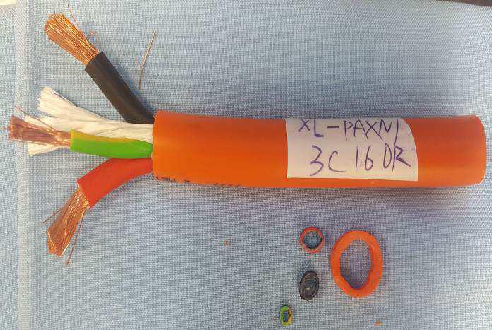
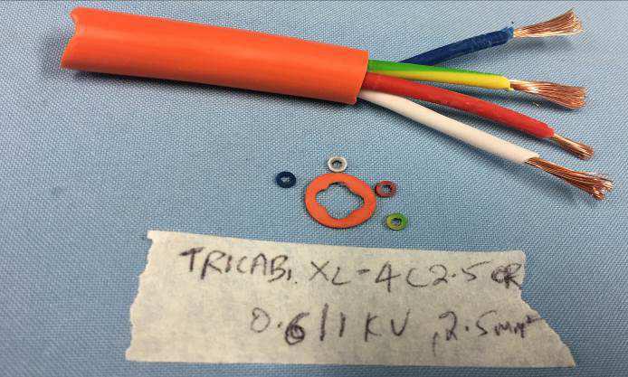
2 Test Report No.: age 2 of 35 Test Report AS/NZS :2005 including amendment 1 Electric cables olymeric insulated for working voltages up to 0.6/1kV Test item particulars: 1C 4mm 2 to 16 mm 2 Circular X-90 insulated, V-90HT sheathed electric cables 2C 1.5mm 2 to 16 mm 2 Circular X-90 insulated, V-90HT sheathed electric cables 3C 1.5mm 2 to 16 mm 2 Circular X-90 insulated, V-90HT sheathed electric cables 4C 1.5mm 2 to 16 mm 2 Circular X-90 insulated, V-90HT sheathed electric cables 5C 1.5mm 2 to 16 mm 2 Circular X-90 insulated, V-90HT sheathed electric cables General remarks: 1. This report shall not be reproduced, except in full. 2. Details in test data / test plan no Specification applied: AS/NZS :2005 inc. amendment 1 AS/NZS 1125:2001 inc. amendment 1 AS/NZS 3808:2000 inc. amendment 1 & 2 4. Reporting of results herein is in accordance with NATA recommendations taking into account U of M. (a) For minimum limits - Where measurement is on the limit or above the limit it is deemed to comply. Where measurement is below the limit it is deemed not to comply. (b) For maximum limits - Where measurement is on the limit or below the limit it is deemed to comply. Where measurement is above the limit it is deemed not to comply. 5. For reporting of results estimated uncertainty for measurement taken into account at 95% confidence level 6. This test report is based on assessment and tests applied to the specific test item(s) as submitted by the client. TÜV Rheinland Australia disclaims any and all responsibility or obligation for any other item. 7. Thickness and conductor resistance test were conducted on all sizes. 8. Manufacturer has declared that X-90 and V-90HT material are identical across the range of the product. 9. XL-AXN/5C2.5 was chosen as representative model. Description of the test item: XL-AXN/1C4, 1C 4mm 2 0.6/1KV rated X-90 insulation, V-90HT sheath with class 5 plain copper conductors. XL-AXN/1C6, 1C 6mm 2 0.6/1KV rated X-90 insulation, V-90HT sheath with class 5 plain copper conductors. XL-AXN/1C10, 1C 10mm 2 0.6/1KV rated X-90 insulation, V-90HT sheath with class 5 plain copper conductors. XL-AXN/1C16, 1C 16mm 2 0.6/1KV rated X-90 insulation, V-90HT sheath with class 5 plain copper conductors. XL-AXN/2C1.5, 1C 1.5mm 2 + Earth 1.5mm 2 0.6/1KV rated X-90 insulation, V-90HT sheath with class 2 plain copper conductors. XL-AXN/2C2.5, 1C 2.5mm 2 + Earth 2.5mm 2 0.6/1KV rated X-90 insulation, V-90HT -T sheath with class 2 plain copper conductors. XL-AXN/2C4, 1C 4mm 2 + Earth 4mm 2 0.6/1KV rated X-90 insulation, V-90HT sheath with class 5 plain copper conductors. XL-AXN/2C6, 1C 6mm 2 + Earth 6mm 2 0.6/1KV rated X-90 insulation, V-90HT sheath with class 5 plain copper conductors. XL-AXN/2C10, 1C 10mm 2 + Earth 4mm 2 0.6/1KV rated X-90 insulation, V-90HT sheath with class 5 plain copper conductors. XL-AXN/2C16, 1C 16mm 2 + Earth 6mm 2 0.6/1KV rated X-90 insulation V-90HT sheath with class 5 plain copper conductors. XL-AXN/3C1.5, 2C 1.5mm 2 + Earth 1.5mm 2 0.6/1KV rated X-90 insulation, V-90HT sheath with class 2 plain copper conductors. XL-AXN/3C2.5, 2C 2.5mm 2 + Earth 2.5mm 2 0.6/1KV rated X-90 insulation, V-90HT sheath with class 2 plain copper conductors. XL-AXN/3C4, 2C 4mm 2 + Earth 4mm 2 0.6/1KV rated X-90 insulation, V-90HT sheath with class 5 plain copper conductors. XL-AXN/3C6, 2C 6mm 2 + Earth 6mm 2 0.6/1KV rated X-90 insulation, V-90HT sheath with class 5 plain copper conductors. XL-AXN/3C10, 2C 10mm 2 + Earth 4mm 2 0.6/1KV rated X-90 insulation, V-90HT sheath with class 5 plain copper conductors.


3 Test Report No.: age 3 of 35 XL-AXN/3C16, 2C 16mm 2 + Earth 6mm 2 0.6/1KV rated X-90 insulation, V-90HT sheath with class 5 plain copper conductors. XL-AXN/4C1.5, 3C 1.5mm 2 + Earth 1.5mm 2 0.6/1KV rated X-90 insulation, V-90HT sheath with class 2 plain copper conductors. XL-AXN/4C2.5, 3C 2.5mm 2 + Earth 2.5mm 2 0.6/1KV rated X-90 insulation, V-90HT sheath with class 2 plain copper conductors. XL-AXN/4C4, 3C 4mm 2 + Earth 4mm 2 0.6/1KV rated X-90 insulation, V-90HT sheath with class 5 plain copper conductors. XL-AXN/4C6, 3C 6mm 2 + Earth 6mm 2 0.6/1KV rated X-90 insulation, V-90HT sheath with class 5 plain copper conductors. XL-AXN/4C10, 3C 10mm 2 + Earth 4mm 2 0.6/1KV rated X-90 insulation, V-90HT sheath with class 5 plain copper conductors. XL-AXN/4C16, 3C 16mm 2 + Earth 6mm 2 0.6/1KV rated X-90 insulation, V-90HT sheath with class 5 plain copper conductors. XL-AXN/5C1.5, 4C 1.5mm 2 + Earth 1.5mm 2 0.6/1KV rated X-90 insulation, V-90HT sheath with class 2 plain copper conductors. XL-AXN/5C2.5, 4C 2.5mm 2 + Earth 2.5mm 2 0.6/1KV rated X-90 insulation, V-90HT sheath with class 2 plain copper conductors. XL-AXN/5C4, 4C 4mm 2 + Earth 4mm 2 0.6/1KV rated X-90 insulation, V-90HT sheath with class 5 plain copper conductors. XL-AXN/5C6, 4C 6mm 2 + Earth 6mm 2 0.6/1KV rated X-90 insulation, V-90HT sheath with class 5 plain copper conductors. XL-AXN/5C10, 4C 10mm 2 + Earth 4mm 2 0.6/1KV rated X-90 insulation V-90HT sheath with class 5 plain copper conductors. XL-AXN/5C16, 4C 16mm 2 + Earth 6mm 2 0.6/1KV rated X-90 insulation, V-90HT sheath with class 5 plain copper conductors. Markings on cables:
4 Test Report No.: age 4 of 35 Markings of cable drums:
5 Test Report No.: age 5 of 35
6 Test Report No.: age 6 of 35 Options/accessories/ancillary equipment: The equipment was tested without any optional accessory installed. Hence, this report does not cover parameters that are influenced by the installation of optional accessory that might affect safety in the meaning of this standard.
7 Test Report No.: age 7 of 35 AS/NZS : CONDUCTORS Conductors shall comply with the relevant requirements of AS/NZS 1125 lain stranded conductors for 1.5mm² - 2.5mm² lain flexible conductors (Class 5) for 4mm² - 16mm² Where tinning is provided, any wires taken from the completed cable need not comply with the continuity test for tin plating Aluminium may be used for conductors of cross sectional areas 16mm 2 and above For aerial cables conductors shall be hard-drawn copper or aluminium. Separator tape may be used over the conductor. If not adhere to insulation, it shall be coloured or opaque. Copper conductors Not aerial cable No separator tape used 6 INSULATION Used insulation material X-90 Insulation shall comply with the requirements of the relevant parts of AS/NZS Aerial and fixed cables for outdoor applications shall be VC that contains a minimum of 1% carbon black by weight. 6.2 The insulation shall be applied over, but shall not adhere to, the conductor. For unsheathed multicore flat cables adjacent cores shall be connected by a web such that the cores can be easily separated by tearing. Sheathed cables 6.3 Thickness of insulation The average thickness of the insulation (ti) shall be not less than the thickness specified in Table 1 Required: Core mm 2 0.7mm Earth 1.5mm 2 0.5mm 2.5mm 2 0.6mm 4-6mm 2 0.7mm Measured: XL-AXN/1C4 (4mm²): White:1.0mm XL-AXN/1C6 (6mm²): White:0.7mm XL-AXN/1C10 (10mm²): White:1.0mm XL-AXN/1C16 (16mm²):
8 Test Report No.: age 8 of 35 AS/NZS :2005 White:0.8mm XL-AXN/2C1.5 (1.5mm²): Red:1.0mm Black:0.9mm XL-AXN/2C2.5 (2.5mm²): Red:0.8mm Black:0.8mm XL-AXN/2C4 (4mm²): Red:0.8mm Black:0.7mm XL-AXN/2C6 (6mm²): Red:0.9mm Black:0.9mm XL-AXN/2C10 (10mm²): Red:1.1mm Black:0.9mm XL-AXN/2C16 (16mm²): Red:0.8mm Black:0.9mm XL-AXN/3C1.5 (1.5mm²): Red:0.8mm Black:0.9mm Earth: 0.9mm XL-AXN/3C2.5 (2.5mm²): Red:0.9mm Black:0.9mm Earth: 0.8mm XL-AXN/3C4 (4mm²): Red:0.9mm Black:0.9mm Earth: 0.9mm XL-AXN/3C6 (6mm²): Red:1.0mm Black:0.9mm Earth: 0.9mm XL-AXN/3C10 (10mm²): Red:1.0mm Black:1.1mm Earth: 0.8mm XL-AXN/3C16 (16mm²): Red:1.1mm Black:1.0mm Earth: 0.8mm XL-AXN/4C1.5 (1.5mm²): Red:0.8mm White:0.9mm Blue:0.8mm Earth: 0.7mm XL-AXN/4C2.5 (2.5mm²): Red:0.9mm White:0.9mm Blue:0.8mm
9 Test Report No.: age 9 of 35 AS/NZS :2005 Earth: 0.8mm XL-AXN/4C4 (4mm²): Red:0.9mm White:0.9mm Blue:0.9mm Earth: 0.9mm XL-AXN/4C6 (6mm²): Red:0.9mm White:0.8mm Blue:0.9mm Earth: 0.8mm XL-AXN/4C10 (10mm²): Red:1.0mm White:1.0mm Blue:1.1mm Earth: 0.9mm XL-AXN/4C16 (16mm²): Red:0.8mm White:0.8mm Blue:1.0mm Earth: 0.8mm XL-AXN/5C1.5 (1.5mm²): Red:0.8mm White:0.9mm Black: 0.9mm Blue:0.9mm Earth: 0.9mm XL-AXN/5C2.5 (2.5mm²): Red:0.8mm White:0.8mm Black: 0.7mm Blue:0.8mm Earth: 0.8mm XL-AXN/5C4 (4mm²): Red:0.9mm White:0.9mm Black: 0.9mm Blue:1.0mm Earth: 0.9mm XL-AXN/5C6 (6mm²): Red:0.8mm White:0.8mm Black: 0.9mm Blue:1.0mm Earth: 0.9mm XL-AXN/5C10 (10mm²): Red:0.8mm White:0.9mm Black: 1.0mm Blue:1.0mm Earth: 0.8mm XL-AXN/5C16 (16mm²): Red:0.8mm
10 Test Report No.: age 10 of 35 AS/NZS :2005 Minimum thickness at any point shall not fall below the specified thickness by more than 10% of the specified thickness plus 0.10 mm, i.e.: minimum thickness = (0.90ti 0.10 mm). White:0.9mm Black: 0.8mm Blue:0.8mm Earth: 0.9mm Required: Core mm mm Earth 1.5mm mm 2.5mm mm 4-6mm mm Measured: XL-AXN/1C4 (4mm²): White:0.74mm XL-AXN/1C6 (6mm²): White:0.65mm XL-AXN/1C10 (10mm²): White:0.86mm XL-AXN/1C16 (16mm²): White:0.54mm XL-AXN/2C1.5 (1.5mm²): Red:0.68mm Black:0.54mm XL-AXN/2C2.5 (2.5mm²): Red:0.70mm Black:0.66mm XL-AXN/2C4 (4mm²): Red:0.59mm Black:0.53mm XL-AXN/2C6 (6mm²): Red:0.73mm Black:0.70mm XL-AXN/2C10 (10mm²): Red:1.00mm Black:0.75mm XL-AXN/2C16 (16mm²): Red:0.62mm Black:0.69mm XL-AXN/3C1.5 (1.5mm²): Red:0.66mm Black:0.79mm Earth: 0.66mm XL-AXN/3C2.5 (2.5mm²): Red:0.86mm Black:0.64mm Earth: 0.64mm XL-AXN/3C4 (4mm²): Red:0.81mm Black:0.68mm Earth: 0.64mm XL-AXN/3C6 (6mm²):
11 Test Report No.: age 11 of 35 AS/NZS :2005 Red:0.83mm Black:0.78mm Earth: 0.78mm XL-AXN/3C10 (10mm²): Red:0.82mm Black:0.87mm Earth: 0.72mm XL-AXN/3C16 (16mm²): Red:0.77mm Black:0,78mm Earth: 0.68mm XL-AXN/4C1.5 (1.5mm²): Red:0.68mm White:0.59mm Blue:0.59mm Earth: 0.53mm XL-AXN/4C2.5 (2.5mm²): Red:0.65mm White:0.80mm Blue:0.68mm Earth: 0.67mm XL-AXN/4C4 (4mm²): Red:0.73mm White:0.85mm Blue:0.79mm Earth: 0.73mm XL-AXN/4C6 (6mm²): Red:0.77mm White:0.65mm Blue:0.78mm Earth: 0.70mm XL-AXN/4C10 (10mm²): Red:0.92mm White:0.97mm Blue:1.02mm Earth: 0.79mm XL-AXN/4C16 (16mm²): Red:0.75mm White:0.61mm Blue:0.71mm Earth: 0.58mm XL-AXN/5C1.5 (1.5mm²): Red:0.69mm White:0.76mm Black: 0.69mm Blue:0.68mm Earth: 0.54mm XL-AXN/5C2.5 (2.5mm²): Red:0.57mm White:0.79mm Black: 0.54mm Blue:0.54mm Earth: 0.60mm
12 Test Report No.: age 12 of 35 AS/NZS :2005 XL-AXN/5C4 (4mm²): Red:0.58mm White:0.80mm Black: 0.75mm Blue:0.64mm Earth: 0.58mm XL-AXN/5C6 (6mm²): Red:0.62mm White:0.53mm Black: 0.79mm Blue:0.79mm Earth: 0.68mm XL-AXN/5C10 (10mm²): Red:0.66mm White:0.71mm Black: 0.81mm Blue:0.75mm Earth: 0.60mm XL-AXN/5C16 (16mm²): Red:0.54mm White:0.66mm Black: 0.64mm Blue:0.60mm Earth: 0.57mm 6.4 Core identification The colours green and yellow, either alone or in combination with any other colour shall not be used except: (a) when yellow printed characters identify cores by figures and words; or (b) for earth cores as described in Clause For other than unsheathed aerial cables, cores shall be clearly and durably identified by either colours or figures followed by words, in accordance with Clause or Clause 6.4.4, as appropriate. For unsheathed multicore flat cables, including aerial cables, either one of the cores of a 2-core cable and the centre core of a 3-core cable shall be identified for use as a neutral by at least 4 evenly spaced (approximately) longitudinal ribs. Earth conductors shall be durably coloured with a combination of green and yellow, applied so that in any 15 mm length of core, one of these colours covers not less than 30% and not more than 70% of the surface of the core, the other colour covering the remainder of the surface. The mass of the insulation shall be either green or yellow, the other colour may be part of the mass or at the surface only. For earth cores as described in Clause Core is identified by colours Not such cable
13 Test Report No.: age 13 of 35 AS/NZS :2005 For other than earth conductors, the colouring for identification may be within the mass or at the surface of the core insulation or, where cores covered the covering may be coloured. Both colouring methods are used Recommended core colors: hase cores: red, white, blue Neutral core: black. Earth core: green/yellow Each figure shall be followed by word that spells that figure (a) Numerals (1); (2); (3); etc. shall indicate active cores Zero (0) shall be used for neutral core (b) Height of characters (c) rinting in a contrasting colour (d) Figures spaced not more than 100mm apart 7 ASSEMBLY OF CORES 7.1 For multicore flat cables the cores shall be laid parallel in the same plane Not such cable 7.2 Circular cables Cores, other than any centre core in circular cables, shall be laid up in helical, helical SZ, or waveform configuration When used, fillers, barrier/binder tapes and other binders shall be compatible with the other materials of the cable with which they are in contact. Unless specified otherwise, the use of fillers, barrier/binder tapes and other binders is optional. 8 BEDDING 8.1 Bedding complying with the requirements of this Clause or an oversheath complying with the requirements of Clause 13, shall be provided directly under any metallic layer. Where dissimilar metallic layers are used, i.e. where electrolysis and galvanic corrosion is possible or electric potential differences may occur (e.g. one metallic layer is used as a neutral while other metallic layers are earthed), electrical separation is required. In this case bedding shall not be used and the metallic layers shall be separated by a separation layer complying with Clause 10. No bedding
14 Test Report No.: age 14 of 35 AS/NZS : The bedding shall comprise non-metallic materials, either extruded or taped Taped bedding shall comprise one or more tapes applied to form a layer. For multicore cables with circular cores with a conductor size greater than 16mm2, fillers shall be used in the outer interstices Extruded bedding shall be applied over, but not adhere to the core assembly or underlying cable component. However, any binder or a barrier tape may adhere to the bedding. For multicore cables with circular cores with a conductor size greater than 16 mm2, the outer interstices between the cores shall be filled by either fillers or the bedding. No taped bedding used No extruded bedding used 8.4 Thickness of bedding Except as provided for in Clause 8.4.2, the thickness of bedding shall be derived from Table Where the metallic screen or concentric conductor to be applied over the core or core assembly comprises one or more metallic tapes of not greater than 0.08 mm nominal thickness, or wires not greater than 0.50 mm nominal diameter, the approximate thickness of the taped bedding may be reduced to 0.1 mm. 9 METALLIC LAYERS The metallic layer applied to single-core cable or the individual cores of a multicore cable shall be nonferromagnetic, except where the cable is for d.c application only. Multiple metallic layers may be applied over the core or core assembly in any order as appropriate for the intended use of the cable. Unless otherwise specified (see Clauses 11 and 12) metallic layers shall be applied over a bedding complying with the requirements of Clause 8 or a separation layer complying with the requirements of Clause SEARATION LAYER 10.1 Extruded separation layer(s) shall be applied when electrical or electrochemical separation between metallic layers is required 10.2 The separation layer shall comprise an appropriate material as specified in Clause 13.2, and shall be applied as specified in Clause (13.2) Separation layer material
15 Test Report No.: age 15 of 35 AS/NZS :2005 Separation layer shall comply with the requirements of the relevant parts of AS/NZS 3808 (13.3) The separation layer shall not adhere to the underlying cable component, except for any barrier tape or binder Thickness The average thickness of the separation layer (Ts) shall be not less than the nominal thickness calculated by the following equation Ts = 0.02Du mm rounded off to 0.1mm, subject to a minimum of 1.2mm Minimum thickness at any point shall not fall below the specified thickness by more than 20% of the specified thickness plus 0.20 mm, i.e.: minimum thickness = (0.80Ts 0.20 mm). 11 ARMOUR 11.1 Armour shall consist of galvanized low-carbon (mild) steel wires complying with AS/NZS 3863 or steel tape having a tensile strength in the range 300 to 450Ma. For non-ferromagnetic armour applications an aluminium wire armour may be used The nominal diameter of the armour wire or the nominal thickness of the armour tape shall be not less than the appropriate values given in Tables 3 and 4, respectively The armour shall be applied over an extruded bedding complying with the requirements of Clause 8, or over a separation layer complying with the requirements of Clause Wire armour shall be applied helically with minimal gap between adjacent wires. Where double-wire armour is required, a separator comprising a layer of non-hygroscopic material of approximately 0.5 mm thickness shall be applied between the concentric layers of armour. For single-wire armour, or the inner layer of double-wire armour, the lay direction shall be opposite to the lay direction of helically laidup cores, or left-hand over helical S-Z or waveform laid-up cores. The outer layer of double wire armour shall be in the opposite direction to the inner layer. Joints in the armour wires shall be brazed or welded and any surface irregularities shall be removed.
16 Test Report No.: age 16 of 35 AS/NZS : Tape armour shall comprise steel tapes applied helically in two layers with the same direction of lay, so that the outer tape is centred approximately over the gap of the inner tape. The gap between adjacent turns of each tape shall not exceed 50 % of the width of the tape. The direction of lay shall be opposite to that of the cores in the case of helically laidup cores, or left-hand in the case of helical S-Z or waveform laid-up cores. Joints in the tape shall be welded and surface irregularities removed For a cable designed to be installed underground, armour shall be further protected by an oversheath in accordance with Clause METALLIC SHEATH 12.1 The metallic sheath shall be lead alloy E in accordance with AS/NZS The metallic sheath shall be removable without damage to the insulation or underlying core assembly. For single-core cables it may be applied directly over the core. For multicore cables, it shall be applied over an extruded bedding or separation layer The average thickness of the metallic sheath (Tm) shall be not less than the nominal thickness calculated by the following equation Tm = 0.025DuM mm and rounded off to 0.1mm, subject to a minimum of 1.0mm Minimum thickness at any point shall not fall below the specified thickness by more than 5% of the specified thickness plus 0.10 mm, i.e.: minimum thickness = (0.95Tm 0.10 mm) For a cable designed to be installed underground, the metallic sheath shall be further protected by an oversheath in accordance with Clause OVERSHEATH 13.2 Material of oversheath V-90HT Oversheath shall comply with the requirements of the relevant parts of AS/NZS The oversheath shall not adhere to the underlying cable component, except for any barrier tape or binder. The oversheath may fill the outer interstices Thickness of oversheath The average thickness of the oversheath (ts) shall be not less than the nominal thickness calculated according to item (a), (b) or (c) and rounded to one XL-AXN/1C4 (4mm²): Required: 1.4mm Measured: 1.6mm
17 Test Report No.: age 17 of 35 AS/NZS :2005 decimal place, as appropriate. XL-AXN/1C6 (6mm²): Required: 1.4mm Measured: 1.6mm XL-AXN/1C10 (10mm²): Required: 1.4mm Measured: 1.5mm XL-AXN/1C16 (16mm²): Required: 1.4mm Measured: 1.8mm XL-AXN/2C1.5 (1.5mm²): Measured: 2.6mm XL-AXN/2C2.5 (2.5mm²): Measured: 1.9mm XL-AXN/2C4 (4mm²): Measured: 2.2mm XL-AXN/2C6 (6mm²): Measured: 1.9mm XL-AXN/2C10 (10mm²): Measured: 2.1mm XL-AXN/2C16 (16mm²): Measured: 2.1mm XL-AXN/3C1.5 (1.5mm²): Measured: 1.8mm XL-AXN/3C2.5 (2.5mm²): Measured: 2.0mm XL-AXN/3C4 (4mm²): Measured: 2.1mm XL-AXN/3C6 (6mm²): Measured: 2.4mm XL-AXN/3C10 (10mm²): Measured: 2.6mm XL-AXN/3C16 (16mm²): Measured: 2.3mm XL-AXN/4C1.5 (1.5mm²): Measured: 1.8mm XL-AXN/4C2.5 (2.5mm²): Measured: 2.0mm XL-AXN/4C4 (4mm²):
18 Test Report No.: age 18 of 35 AS/NZS : The minimum thickness at any point shall not fall below the nominal thickness (ts) by more than one of the following: (a) Unarmoured cables, cables with metallic or metallized tape screen or metal sheath and flexible cables: minimum thickness = (0.85 ts 0.10 mm). Measured: 2.1mm XL-AXN/4C6 (6mm²): Measured: 2.2mm XL-AXN/4C10 (10mm²): Measured: 2.6mm XL-AXN/4C16 (16mm²): Measured: 3.0mm XL-AXN/5C1.5 (1.5mm²): Measured: 2.0mm XL-AXN/5C2.5 (2.5mm²): Measured: 1.8mm XL-AXN/5C4 (4mm²): Measured: 2.5mm XL-AXN/5C6 (6mm²): Measured: 2.1mm XL-AXN/5C10 (10mm²): Measured: 2.4mm XL-AXN/5C16 (16mm²): Measured: 2.6mm XL-AXN/1C4 (4mm²): Required: 1.09mm Measured: 1.30mm XL-AXN/1C6 (6mm²): Required: 1.09mm Measured: 1.45mm XL-AXN/1C10 (10mm²): Required: 1.09mm Measured: 1.44mm XL-AXN/1C16 (16mm²): Required: 1.09mm Measured: 1.31mm XL-AXN/2C1.5 (1.5mm²): Measured: 2.08mm XL-AXN/2C2.5 (2.5mm²): Measured: 1.83mm XL-AXN/2C4 (4mm²):
19 Test Report No.: age 19 of 35 AS/NZS :2005 Measured: 1.98mm XL-AXN/2C6 (6mm²): Measured: 1.69mm XL-AXN/2C10 (10mm²): Measured: 1.92mm XL-AXN/2C16 (16mm²): Measured: 2.23mm XL-AXN/3C1.5 (1.5mm²): Measured: 1.45mm XL-AXN/3C2.5 (2.5mm²): Measured: 1.83mm XL-AXN/3C4 (4mm²): Measured: 1.95mm XL-AXN/3C6 (6mm²): Measured: 2.24mm XL-AXN/3C10 (10mm²): Measured: 2.15mm XL-AXN/3C16 (16mm²): Measured: 1.89mm XL-AXN/4C1.5 (1.5mm²): Measured: 1.46mm XL-AXN/4C2.5 (2.5mm²): Measured: 1.76mm XL-AXN/4C4 (4mm²): Measured: 1.61mm XL-AXN/4C6 (6mm²): Measured: 1.75mm XL-AXN/4C10 (10mm²): Measured: 2.26mm XL-AXN/4C16 (16mm²): Measured: 2.56mm XL-AXN/5C1.5 (1.5mm²): Measured: 1.76mm XL-AXN/5C2.5 (2.5mm²): Measured: 1.56mm
20 Test Report No.: age 20 of 35 AS/NZS :2005 (b) Armoured or wire screened cables or cables with concentric conductor where the oversheath is applied directly over the armour, screen or concentric conductor: minimum thickness = (0.80 ts 0.20 mm) Where the oversheath consists of two layers of material, the nominal thickness of either layer shall be not less than 40 % of the calculated thickness, but in no case less than 1.0 mm. The minimum thickness at any point of the combined layer shall not fall below the calculated thickness by more than that specified in Clause For combined layers that can be separated then the minimum at any point of each layer shall not fall below the calculated value given by the equations in Clause , calculated for each layer and using the nominal thickness for that layer. XL-AXN/5C4 (4mm²): Measured: 2.19mm XL-AXN/5C6 (6mm²): Measured: 1.87mm XL-AXN/5C10 (10mm²): Measured: 2.29mm XL-AXN/5C16 (16mm²): Measured: 1.87mm 14 NON-METALLIC BRAID 15 ROTECTION FROM INSECT ATTACK 16 MARKING 16.1 Information to be marked on cable (a) A registered name or registered mark which enables the manufacturer or supplier of the cord to be identified. TRICAB marked (b) Year of manufacture marked (c) Designation of insulation. X-90 marked (d) (e) Words ELECTRIC CABLE followed by the rated voltage Cables designed for specific application (aerial, DC use only, fixed application only) 0.6/1kV marked Fixed application only (f) Material of conductor if larger than 16mm Means of marking
21 Test Report No.: age 21 of 35 AS/NZS :2005 (a) Marking on outer surface by printing, embossing or stamping (indenting) The distance between two blocks of marking shall not exceed 550 mm (b) Alternative means of marking shall consist of printing on a tape which is included throughout the length of the cord or printing, embossing or stamping (indenting) on the surface of an active core The distance between two blocks of marking shall not exceed 275 mm. <550mm 16.3 Legibility of marking Easily legible 16.4 Marking of packaging (a) Every packaging unit shall have the following information identified by means of an attached tag or label, or by marking directly on the unit: A registered name or registered mark which enables the manufacturer or supplier of the cable to be identified. Marking labels placed on cable drums TRICAB marked (b) Reference to the standard: AS/NZS Marked (c) Voltage rating 0.6/1.0kV marked (d) The number of cores and the size of conductors marked (e) Designation of insulation and sheath X-90 marked, Manufacturer has declared that the sheath material V90-HT will be marked in all future productions (f) The catalogue number, type number, name or other marking to distinguish the cable. Refer to page 2 (g) Length of cable marked 17 TESTS according to Table 6 Test 1 Conductors comply with AS/NZS1125, except tin plating See page 23 Test 2 Conductor resistance See page 23 Test 3 Insulation complies with AS/NZS 3808 See page 27 Test 4 Separation layer complies with AS/NZS 3808 Test 4 Oversheath complies with AS/NZS 3808 See page 29 Test 5 Insulation thickness (clause 6) See page 7 Test 6 Separation thickness (clause 10) Test 6 Oversheath thickness (clause 13) See page 16
22 Test Report No.: age 22 of 35 AS/NZS :2005 Test 7 olyamide jacket thickness (clause 15) Test 8 Armour dimension (clause 11) Test 9 Metallic sheath thickness (clause 12) Test 10 High voltage test for 4h No breakdown Test 12 High voltage test for 5min (a) on single core cables No breakdown (b) 2-, 3- or 4 core cables with conductors 35mm 2 insulated (unsheathed) or insulated and oversheathed (unscreened, unarmoured) No breakdown Test 13 High voltage test for 5min on separation layer Test 14 Compatibility test after ageing Test parameters of ageing 1.a) Tensile Strength of insulation, min 75%of unaged materials 2.a) Elongation of insulation, min 65% of unaged material 1.a) Tensile Strength of separation layer, min 75%of unaged materials 2.a) Elongation of separation layer, min 65% of unaged material 1.b) Tensile Strength of oversheath, min 75%of unaged materials 2.b) Elongation of oversheath, min 65% of unaged material Duration: 240 h Temperature:100 ± 2 C Black: Required: 9.5Ma Measured: 14.0Ma Red: Required: 10.3Ma Measured: 12.0Ma G/Y: Required: 9.7Ma Measured: 11.9Ma Black: Required: 337% Measured: 502% Red: Required: 416% Measured: 490% G/Y: Required: 338% Measured: 489% Required: 10.9Ma Measured: 14.3Ma Required: 188% Measured: 258% Test 15 Vertical flame propagation Charring not extend beyond the limits >250mm below the limit No ignition of filter paper No flaming droplets Test 16 Legibility of marking
23 Test Report No.: age 23 of 35 AS/NZS 1125:2001 inc. amendment 1 2 COER CONDUCTORS 2.2 Material of conductor shall be high conductivity copper wire complying with the chemical composition designation C11000 in AS/NZS Conductors shall be circular, shaped, solid, uniaxial, stranded, multiple-stranded circular, bunched circular, compressed, compacted, milliken or tinsel Manufacturer s statement accepted. stranded 2.4 Joints in conductor No joints Joints are permitted in a solid conductor by welding only. Joints are also permitted in the individual wires of a stranded, uniaxial or bunched conductor and in the individual bunches or strands of a multiple-stranded conductor, from which it is formed. When joining conductors by silver-soldering, resistance butt welding or fusion welding, no joint in a wire shall be closer than 60 mm to that in any other wire or bunch in the same layer. Above restriction shall not apply when welding by cold pressure welding. 2.5 Solid conductors (class 1) Solid conductors shall be plain or metal-coated annealed or hard-drawn copper. Solid conductors used up to max 2.5 mm 2 unless cable standard specifies otherwise The d.c. resistance of conductors at 20 C shall be as specified in Table 2.2 for the relevant nominal cross-sectional area of conductor. Not such conductor Not such conductor Not such conductor 2.6 Stranded conductors (class 2) Stranded conductors shall be plain or metal-coated annealed or hard-drawn copper. The minimum number of wires shall be as specified in Table 2.3 for the relevant nominal cross-sectional area of conductor. 1.5 mm 2, 2.5 mm 2 lain copper 1.5 mm 2 Required number of wires: 3 Number of wires: mm 2 Required number of wires: 3 Number of wires: 35
24 Test Report No.: age 24 of 35 AS/NZS 1125:2001 inc. amendment 1 The d.c. resistance of conductors at 20 C shall be as specified in Table 2.3 for the relevant nominal cross-sectional area of conductor. For stranded circular, uniaxial and circular compressed conductors the individual wires shall be the same nominal diameter. For stranded shaped, circular compacted and Milliken conductors the ratio of the largest wire cross-sectional area to the smallest wire crosssectional area in the conductor shall not exceed 4. The use of circular compacted conductors shall be restricted to conductor sizes of 6 mm2 or greater unless otherwise specified in the appropriate cable Standard. When a Milliken conductor is required, the conductor shall consist of sector-shaped stranded conductors lightly insulated from each other. Required max: 21.6 Ω/km Measured: 19.4 Ω/km 1.5mm 2 : Required max: 13.6 Ω/km Measured: 13.2 Ω/km 2.5mm 2 : Required max: 7.41 Ω/km Measured: 7.29 Ω/km Wires are same diameter Not such conductor Not such conductor Not such conductor 2.8 Flexible conductors (class 5) The wires in Class 5 conductors shall be plain or metal-coated annealed copper. The individual wires shall be the same nominal diameter. The maximum wire diameter shall be as specified in Table 2.4 for the relevant nominal crosssectional area of conductor. The d.c. resistance of conductors at 20 C shall be as specified in Table 2.4 for the relevant nominal cross-sectional area of conductor. 4mm 2-16mm² lain copper 4mm 2 and 6mm² Required max: 0.31 mm Measured: 0.29 mm 10mm 2 and 16mm 2 Required max: 0.41 mm Measured: 0.29 mm 4mm 2 : Required max: 4.95 Ω/km Measured: 4.90 Ω/km 6mm 2 : Required max: 3.30 Ω/km Measured: 3.30 Ω/km 10mm 2 : Required max: 1.91 Ω/km Measured: 1.73 Ω/km 16mm 2 : Required max: 1.21 Ω/km Measured: 1.12 Ω/km 2.9 Flexible conductors (class 6) The wires in Class 5 conductors shall be plain or metal-coated annealed copper. Not such conductor
25 Test Report No.: age 25 of 35 AS/NZS 1125:2001 inc. amendment 1 The individual wires shall be the same nominal diameter. The maximum wire diameter shall be as specified in Table 2.5 for the relevant nominal crosssectional area of conductor. The d.c. resistance of conductors at 20 C shall be as specified in Table 2.5 for the relevant nominal cross-sectional area of conductor Multiple Stranded conductors (rope lay) Wires in conductors shall be plain or tinned annealed copper. The individual wires shall be the same nominal diameter. The maximum wire diameter shall be as specified in Table 2.6 for the relevant nominal crosssectional area of conductor. The d.c. resistance of conductors at 20 C shall be as specified in Table 2.6 for the relevant nominal cross-sectional area of conductor. No multiple stranded conductors Table 2.1 TESTS FOR LAIN OR TINNED COER CONDUCTORS Elongation of annealed conductor wires from stranded circular and bunched circular conductors. 1.5mm²: Required min.: 14% Measured average: 19% No wire found having less than 50% of required elongation. 2.5mm²: Required min.: 14% Measured average: 20% No wire found having less than 50% of required elongation. 4mm²: Required min.: 14% Measured average: 24% No wire found having less than 50% of required elongation. 6mm²: Required min.: 14% Measured average: 25% No wire found having less than 50% of required elongation. 10mm²: Required min.: 14% Measured average: 18% No wire found having less than 50% of required elongation. 16mm²: Required min.: 14% Measured average: 18% No wire found having less than 50% of required elongation.
26 Test Report No.: age 26 of 35 AS/NZS 1125:2001 inc. amendment 1 Coating continuity test for tinned conductors Not required, see page 4 Conductor resistance See page 14
27 Test Report No.: age 27 of 35 AS/NZS 3808:2000 inc. amendment 2 4 MATERIALS Insulation material type X Separation layer material type Ovesheath material type V-90HT - 5 TESTS AND CRITERIA - The properties of materials are specified in the following tables: - Requirements applicable for Insulation material: Table 9, column 2 - Requirements applicable for separation layer material: - Requirements applicable for Oversheath material: Table 5, column 4 - Table 5 Tests and criteria for insulation A Mechanical tests without ageing: A.1 Tensile strength - min Ma 2.5mm² Measured: Red: 13.7 Ma Black:12.7 Ma Earth: 12.9 MA A.2 Elongation at rupture - min. 200% 2.5mm² Measured: Red: 640% Black: 519% Earth: 520% B Mechanical tests after ageing in air oven: 168 h at 135 ± 3 C B.1 Tensile strength - min. 75% of value of unaged specimens 2.5mm² Required: Red: 10.3 Ma Black: 9.5 Ma Earth: 9,7 Ma Measured: Red: 12.0 Ma Black: 11.8 Ma Earth: 10.2 Ma
28 Test Report No.: age 28 of 35 AS/NZS 3808:2000 inc. amendment 2 B.2 Elongation at break - min. 70% of value of unaged specimens 2.5mm² Required: Red: 480% Black: 389% Earth: 390% Measured: Red: 481% Black: 426% Earth: 401% C Melt flow index, maximum D Hot-set test: 15min at 200 ±3 C, load: 200ka D.1 Elongation under load max 175% 2.5mm² Measured: Red 55% D.2 Residual Elongation after cooling max 15% Black 40% Earth 60% 16mm² Measured: Red 10% Black 5% Earth 50% 2.5mm² Measured: Red 7.5% Black 12.5% Earth 2.5% 16mm² Measured: Red 5% Black 2.5% Earth 5% E Carbon black content, minimum F Carbon black dispersion G Electrical Characteristics:
29 Test Report No.: age 29 of 35 AS/NZS 3808:2000 inc. amendment 2 1. Insulation resistance constant (Ki) at 20 C minimum 3000 (GΩm) 2. Insulation resistance constant (Ki) at elevated temperature minimum 3.0 (GΩm) at 90 C 4mm² Measured: Red: 10603GΩ.m Black: 12749GΩ.m Earth: 5807GΩ.m 16mm² Measured: Red: 21681GΩ.m Black: 27600GΩ.m Earth: 14921GΩ.m 4mm² Measured: Red: 28.4GΩ.m Black: 43.9GΩ.m Earth: 24.5GΩ.m 16mm² Measured: Red: 179.2GΩ.m Black: 233.5GΩ.m Earth: 67.7GΩ.m Table 6 TESTS AND CRITERIA FOR OVERSHEATH A Mechanical tests without ageing: A.1 Tensile strength - min. 12.5Ma Measured: 14.5Ma A.2 Elongation at rupture - min. 150% Measured: 289% B Mechanical tests after ageing in air oven: 504h at 120 ± 2 C B.1 Tensile strength min. 75% of value of unaged specimens Required: 10.9Ma Measured: 14.4Ma B.2 Elongation at break min. 65% of value of unaged specimens C Loss of mass: 120h at 120 ±2 C - max. 2.5 mg/cm 2 of exposed area D ressure test at high temperature: 90 ± 2 C, Indentation - max. 50% Required: 188% Measured: 218% 1.5mm 2 Measured: 0.4 mg/cm 2 1.5mm² Measured: 26% 16mm² Measured: 23% E Heat shock test - No cracks No cracks F Hot-set test: F.1 Elongation under load F.2 Residual Elongation after cooling
30 Test Report No.: age 30 of 35 AS/NZS 3808:2000 inc. amendment 2 G Exudation of plasticiser There shall be no greasiness or droplets of liquid No greasiness or droplets of liquid


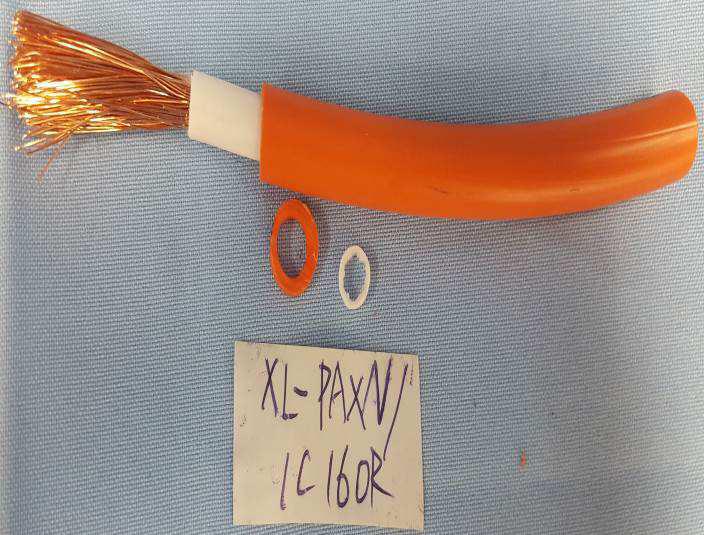
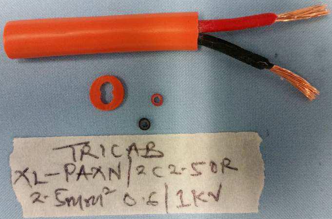
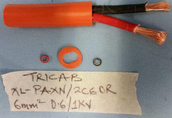
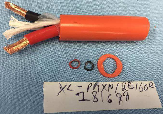
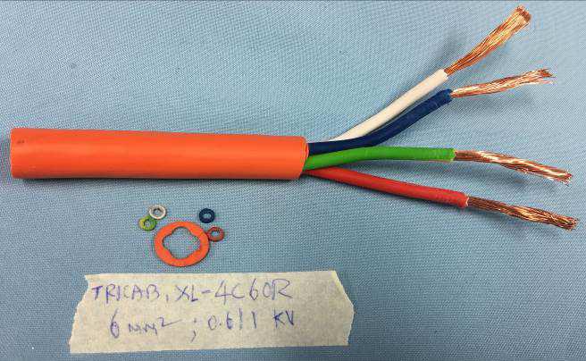
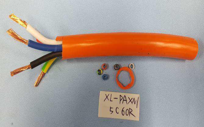
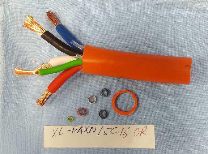
31 Test Report No.: age 31 of 35 HOTOS


32 Test Report No.: age 32 of 35


33 Test Report No.: age 33 of 35


34 Test Report No.: age 34 of 35


35 Test Report No.: age 35 of 35 END OF TEST REORT
Test Report No.: Page 2 of 34
 Test Report No.: 50093985 001 age 2 of 34 Test Report AS/NZS 5000.2:2006 Electric cables olymeric insulated for working voltages up to and including 450/750V Test item particulars: 1C 4mm 2 to 16 mm 2
MATERIAL STANDARD FOR CABLES AND WIRES
 MATERIAL STANDARD FOR CABLES AND WIRES CONTENTS : PAGE No. 1. SCOPE... 2 2. SERVICE CONDITIONS... 2 3. REFERENCES AND STANDARDS... 2 4. UNITS... 3 5. CABLE DESIGN AND CONSTRUCTION... 3 5.1 Applicable Cable
NPS/002/018 Technical Specification for Pilot, Control and Telephone Cables
 Version: 4.1 Date of Issue: February 2016 Page: 1 of 25 NPS/002/018 Technical Specification for Pilot, Control and Telephone Cables 1. Purpose The purpose of this document is to detail the requirements
NPS/002/018 Technical Specification for Pilot, Control and Telephone Cables
 Version: 4.0 Date of Issue: October 2015 Page: 1 of 21 NPS/002/018 Technical Specification for Pilot, Control and Telephone Cables 1. Purpose The purpose of this document is to detail the requirements
Specification FOR. 12.7/22KV AL-CV/WS 12.7/22KV Aluminum Conductor XLPE Insulated Copper Wire Screened PVC Sheathed Power Cable.
 Spec. No. GO 5821-4361Rev.2 Issued date : July 13, 2005 Revised 1 date : April 29, 2015 Revised 2 date : February 19, 2016 Specification FOR 12.7/22KV AL-CV/WS 12.7/22KV Aluminum Conductor XLPE Insulated
0.6/1 kv LOW VOLTAGE CONTROL CABLES. Conductors. Insulation. Assembly. Standard Colour Code. Armour (Optional) Screening (Optional) Outer Sheath
 Screening (Optional) Outer Sheath") 0.6/1 kv LOW VOLTAGE CONTROL CABLES PVC OR XLPE INSULATED, PVC SHEATHED AS PER IEC 60502-1 Conductors Conductors shall be Circular Stranded, Class 2 as per IEC 60228, BS EN 60228. Upon request, Solid Circular
0.6/1 kv LOW VOLTAGE CONTROL CABLES PVC OR XLPE INSULATED, PVC SHEATHED AS PER IEC 60502-1 Conductors Conductors shall be Circular Stranded, Class 2 as per IEC 60228, BS EN 60228. Upon request, Solid Circular
Test Report. Specifications Cu/V-90/5V /lkV 1X 630 mm2 (round. Inspected unit Nanvang Cable (Tianjin) Co., Ltd.
 Co., Ltd.") Test purpose Commission Test Commission Test,- Nn DX130292 TESTING CNAS L0153 Test Report Name of sample pyc SDI Specifications Cu/V-90/5V-90 0.6/lkV 1X 630 mm2 (round Inspected unit Nanvang Cable (Tianjin)
Test purpose Commission Test Commission Test,- Nn DX130292 TESTING CNAS L0153 Test Report Name of sample pyc SDI Specifications Cu/V-90/5V-90 0.6/lkV 1X 630 mm2 (round Inspected unit Nanvang Cable (Tianjin)
DRAFT TANZANIA STANDARD. Part 7: Underground Power Cables for rated voltages 0.6kV/1kV (Um 1.2kV)
") EDC3 (5239) P3 Mini-Grid Systems DRAFT TANZANIA STANDARD Part 7: Underground Power Cables for rated voltages 0.6kV/1kV (Um 1.2kV) TANZANIA BUREAU OF STANDARDS TBS 2017 First Edition 2017 Table of Contents
EDC3 (5239) P3 Mini-Grid Systems DRAFT TANZANIA STANDARD Part 7: Underground Power Cables for rated voltages 0.6kV/1kV (Um 1.2kV) TANZANIA BUREAU OF STANDARDS TBS 2017 First Edition 2017 Table of Contents
SPECIFICATION FOR FRLS POWER CABLES
 SPECIFICATION FOR FRLS POWER CABLES 1.0 SCOPE This specification cover the technical requirements of design, manufacture, testing and delivery to site of Power Cables of 1100V grade with FRLS PVC Sheathed,
NPS/002/020 Technical Specification for 11 & 20kV Power Cables
 Version:- 3.1 of Issue:- Nov - 09 Page 1 of 11 NPS/002/020 Technical Specification for 11 & 20kV Power Cables 1. Purpose The purpose of this document is to detail Northern Powergrid (the Company) requirements
Cables for Railway Signalling Applications General Requirements
 Discipline: Engineering (Signalling) Category: Procedure Cables for Railway Signalling Applications General Requirements ESA-11-01 Applicability ARTC Network Wide Primary Source ESA-02-01 Document Status
Technical Specification for PVC Insulated Low Voltage Neutral Screened Copper Cable
 Ergon Energy Corporation Limited Technical Specification for PVC Insulated Low Voltage Neutral Screened Copper Cable ETS03-01-05 Specification ETS03-01-05 Ver 4 Contents 1. Purpose and Scope... 1 2. References...
1. All Members of Power Cables Sectional Committee, ET 09; 2. All Members of Electrotechnical Division Council; and 3. All other Interested.
 DRAFT IN WIDE CIRCULATION DOCUMENT DESPATCH ADVICE Reference Date ET 09/T-45 03-05-2011 TECHNICAL COMMITTEE ETD 09 --------------------------------------------------------------------------------------------------------------
TYPE TEST REPORT OF 11 KV 3 x 240 mm² CU/XLPE/SWA/PVC CABLE. Kinectrics International Inc. Report No.: K RC-0001-R00.
 To: National Cables Industry P.O Box 27472 Al Dhaid Road, Al Sajja Industrial Area Sharjah U.A.E TYPE TEST REPORT OF 11 KV 3 x 240 mm² CU/XLPE/SWA/PVC CABLE Kinectrics International Inc. Report No.: K-422341-RC-0001-R00
Comparison of BS 5308, PAS 5308 and BS EN
 Comparison of BS 5308, PAS 5308 and BS EN 50288 Scope BS 5308 Part 1: 1986- Instrumentation Cables Part 1. Specification for Polyethylene Insulated Cables (withdraw, superseded by BS EN 50288-7) BS 5308
NPS/002/023 Technical Specification for 132kV Power Cables.
 Version:- 2.2 of Issue:- June 09 Page 1 of 11 NPS/002/023 Technical Specification for 132kV Power Cables. 1. Purpose The purpose of this document is to detail the technical requirements of Northern Powergrid
P.V.C. INSULATED UNARMOURED COPPER CABLES
 083 : 2007 CEB SPECIFICATION P.V.C. INSULATED UNARMOURED COPPER CABLES CEYLON ELECTRICITY BOARD SRI LANKA Specification for P.V.C. INSULATED UNARMOURED COPPER CABLES CEB Specification 083 : 2007 CEYLON
*** Supercedes: BECO E and COM , , & ***
 7/27/09 Page 1 of 9 R5 *** Supercedes: BECO E2.9-27.4 and COM 1-0696, 2-0196, & 5-0385 *** 1.0 Scope #2 AWG to 1000 KCMIL CONCENTRIC NEUTRAL JACKETED CABLES RATED 5-35 kv These Specifications cover single
Wire and Cable Heat-shrink Tubing Non-shrink Tubing Braided Sleeving Screening Braids Moulded Parts Terminals and Splices Wire and Cable Markers
 Wire and Cable Heat-shrink Tubing Non-shrink Tubing Braided Sleeving Screening Braids Moulded Parts Terminals and Splices Wire and Cable Markers Accessories Connectors Backshells Bonding Leads Metal Braids
Type 1 Machine Cable. Oxygen free tinned annealed copper wire interwoven with high tensile poly-yarn
 Mining Cable Type 1 Machine Cable Application: Typically used for interconnection of control boxes or motors on non-mobile or fixed apparatus. Used when exposure to heat is not an issue and where added
INTERNATIONAL STANDARD
 INTERNATIONAL STANDARD IEC 60502-2 Second edition 2005-03 Power cables with extruded insulation and their accessories for rated voltages from 1 kv (U m = 1,2 kv) up to 30 kv (U m = 36 kv) Part 2: Cables
TECHNICAL SPECIFICATION FOR L. T. XLPE POWER CABLE
 TECHNICAL SPECIFICATION FOR L. T. XLPE POWER CABLE SEAL & SIGNATURE OF THE TENDERER PAGE 1 OF 14 TECHNICAL SPECIFICATION FOR LT XLPE POWER CABLES (SPECIFICATION NO.MM/I/LTXLPE/2006) 1. SCOPE: The specification
SECTION 7.3 TECHNICAL SPECIFICATION OF POWER CABLES & CONDUCTOR
 SECTION 7.3 TECHNICAL SPECIFICATION OF POWER CABLES & CONDUCTOR 458 7.3.1 11 KV Cables 7.3.1.1 General Where a Manufacturer s Standard or a national Standard equal to or better than the appropriate specified
Construction guideline
 1/6 1) SUMMARY OF ABBREVIATIONS FOR CABLE CONSTRUCTION ELEMENTS MSR - : EUPEN code for INSTRUMENTATION CABLES JE - : cable for INDUSTRIAL ELECTRONICS RD - : cable for CONTROL SYSTEMS INSULATION MATERIALS:
137-1: 2015 CEB SPECIFICATION. XLPE INSULATED SINGLE CORE UNDERGROUND CABLES OF 11 kv RATED VOLTAGE
 137-1: 2015 CEB SPECIFICATION XLPE INSULATED SINGLE CORE UNDERGROUND CABLES OF 11 kv RATED VOLTAGE CEYLON ELECTRICITY BOARD SRILANKA Telephone: +94 11 232 8051 Fax: +94 11 232 5387 CONTENTS Page 1.0 Scope
Technical Specification for Low Voltage Aerial Bundled HDPE Insulated Cables
 Ergon Energy Corporation Limited Technical Specification for Low Voltage Aerial Bundled HDPE Insulated Cables ETS03-01-04 Specification ETS03-01-04 Ver 2 Contents 1. Purpose and Scope... 1 2. References...
Technical Specification for Insulated Low Voltage Single Core Copper Cable
 Ergon Energy Corporation Limited Technical Specification for Insulated Low Voltage Single Core Copper Cable ETS03-01-03 Specification ETS03-01-03 Ver 3 Contents 1. Purpose and Scope... 1 2. References...
MEDIUM VOLTAGE XLPE INSULATED POWER CABLES [6.35/11kV Copper XLPE Three-Core HDPE Sheathed]
![MEDIUM VOLTAGE XLPE INSULATED POWER CABLES [6.35/11kV Copper XLPE Three-Core HDPE Sheathed]](/thumbs/78/76777314.jpg "MEDIUM VOLTAGE XLPE INSULATED POWER CABLES [6.35/11kV Copper XLPE Three-Core HDPE Sheathed]") [6.35/11kV Copper XLPE Three-Core HDPE Sheathed] APPLICATION Mostly used as feeder electric cable for power distribution network such as power supply station, substation, switching system etc. They are
[6.35/11kV Copper XLPE Three-Core HDPE Sheathed] APPLICATION Mostly used as feeder electric cable for power distribution network such as power supply station, substation, switching system etc. They are
P.V.C. INSULATED ALUMINIUM SERVICE MAIN WIRE-FINISHED PRODUCT
 CEB SPECIFICATION 005-1: 2012 P.V.C. INSULATED ALUMINIUM SERVICE MAIN WIRE-FINISHED PRODUCT CEYLON ELECTRICITY BOARD SRI LANKA Telephone: +94 11 232 0953 Fax: +94 11 232 3935 CONTENTS PAGE 1. Scope 03
SCHEDULE ' A ' TECHNICAL SPECIFICATION FOR L.T.PVC POWER AND CONTROL CABLES FOR DISTRIBUTION NETWORK IN MAHARASHTRA
 SCHEDULE ' A ' TECHNICAL SPECIFICATION FOR L.T.PVC POWER AND CONTROL CABLES FOR DISTRIBUTION NETWORK IN MAHARASHTRA (SPECIFICATION NO.MM/I/LTPVC & CONTROL/2006) MAHARASHTRA STATE ELECTRICITY DISTRIBUTION
NUCLEAR POWER CORPORATION OF INDIA LTD. (A GOVT. OF INDIA ENTERPRISE) SPECIFICATION NO.PB-E-542/REV. No.0
 SPECIFICATION NO.PB-E-542/REV. No.0") REVISION NO. 0 NUCLEAR POWER CORPORATION OF INDIA LTD. (A GOVT. OF INDIA ENTERPRISE) SPECIFICATION NO.PB-E-542/REV. No.0 PAGE NO. 1 OF 24 DATE OF ISSUE (MONTH/YEAR) TOTAL NO. OF PAGES (Including cover
REVISION NO. 0 NUCLEAR POWER CORPORATION OF INDIA LTD. (A GOVT. OF INDIA ENTERPRISE) SPECIFICATION NO.PB-E-542/REV. No.0 PAGE NO. 1 OF 24 DATE OF ISSUE (MONTH/YEAR) TOTAL NO. OF PAGES (Including cover
L1-CHE-SPE-171 TECHNICAL SPECIFICATION FOR ELECTRIC CABLE
 Engineering Specification Electrical Networks L1-CHE-SPE-171 TECHNICAL SPECIFICATION FOR ELECTRIC CABLE 400mm 2 ALUMINIUM OR COPPER CONDUCTOR 3.8/6.6kV XLPE INSULATED WITHOUT METALLIC SCREEN PVC Version:
DETAIL SPECIFICATION SHEET CABLE, ELECTRICAL, -20 C TO +105 C, 1000 VOLTS, TYPE LSFSGU
 INCH-POUND MIL-DTL-24643/17F 1 October 2009 SUPERSEDING MIL-DTL-24643/17E 22 August 2002 DETAIL SPECIFICATION SHEET CABLE, ELECTRICAL, -20 C TO +105 C, 1000 VOLTS, TYPE LSFSGU This specification is approved
CONSULTATIONS TECHNICAL GUIDELINE. HVDC extruded cable
 UNIT, BU1SNESS AREA OUR REFERENCE TR14-02-2E DATE 2018-01-24 CONSULTATIONS TECHNICAL GUIDELINE EDITION 1 APPROVED HVDC extruded cable This technical guideline describes the basic design and construction
NEMA Standards Publication No. WC ICEA Publication No. S
 NEMA Standards Publication No. WC 71-1999 ICEA Publication No. S-96-659-1999 Standard for Nonshielded Cables Rated 2001-5000 Volts for use in the Distribution of Electric Energy Published by National Electrical
IEEE 1580 Type P MOR Polyrad XT-125 Multi Conductor
 TABLE OF CONTENTS SECTION SUBJECT PAGE I. SCOPE...1 II. APPLICABLE DOCUMENTS...1 III. CONDUCTOR...2 IV. SEPARATOR...2 V. INSULATION...2 A. Physical Properties...2 B. Electrical Properties...3 C. Qualification
Four Core, Aluminum Conductor Extruded Cross - Linked Polyethylene (XLPE) Insulated Power Cable
 Insulated Power Cable") Edition Nº: 7 Issued date: February, 2017 NPS 91 Specifications for THE ISRAEL ELECTRIC CORPORATION LTD. Specification No. NPS-91 for Four Core, Aluminum Conductor Extruded Cross - Linked Polyethylene
Edition Nº: 7 Issued date: February, 2017 NPS 91 Specifications for THE ISRAEL ELECTRIC CORPORATION LTD. Specification No. NPS-91 for Four Core, Aluminum Conductor Extruded Cross - Linked Polyethylene
SOUTH CAROLINA ELECTRIC COOPERATIVES' PRIMARY UNDERGROUND POWER CABLE SPECIFICATION
 SOUTH CAROLINA ELECTRIC COOPERATIVES' PRIMARY UNDERGROUND POWER CABLE SPECIFICATION 1.0 SCOPE 1.1 This specification covers the construction, mechanical, and electrical requirements of single conductor,
Four Core, Copper Conductor Extruded Cross - Linked Polyethylene (XLPE) Insulated Power Cable
 Insulated Power Cable") Edition Nº: 9 THE ISRAEL ELECTRIC CORPORATION LTD. Specification No. NPS-76 for Four Core, Copper Conductor Extruded Cross - Linked Polyethylene (XLPE) Insulated Power Cable for Rated Voltage U0/U = 0.6/1.0
Edition Nº: 9 THE ISRAEL ELECTRIC CORPORATION LTD. Specification No. NPS-76 for Four Core, Copper Conductor Extruded Cross - Linked Polyethylene (XLPE) Insulated Power Cable for Rated Voltage U0/U = 0.6/1.0
STANDARDS UPDATE NOTICE (SUN) ISSUED: February 23, 2018
 ISSUED: February 23, 2018") STANDARDS UPDATE NOTICE (SUN) ISSUED: February 23, 2018 STANDARD INFORMATION Standard Number: UL 83 / CSA C22.2 No 75 / NMX-J-010-ANCE Standard Name: Thermoplastic-Insulated Wires and Cables Standard Edition
STANDARDS UPDATE NOTICE (SUN) ISSUED: February 23, 2018 STANDARD INFORMATION Standard Number: UL 83 / CSA C22.2 No 75 / NMX-J-010-ANCE Standard Name: Thermoplastic-Insulated Wires and Cables Standard Edition
SafeX110 Single Core Flexible Tinned Copper Cable
 LSZH 110 C Flexible SafeX110 Single Core Flexible Tinned Copper Cable Application: Wiring of switchboards, control, general wiring, instrumentation and communication systems. Used where low smoke, zero
STANDARD SPECIFICATION FOR SIGNAL CABLE. A. This Specification provides for single and multi-conductor insulated and jacketed cable for
 STANDARD SPECIFICATION FOR SIGNAL CABLE 1.01 SCOPE A. This Specification provides for single and multi-conductor insulated and jacketed cable for installation in direct contact with the earth, in ducts,
11-SDMS-01 REV. 03 ( )
") 11-SDMS-01 REV. 03 (19-07-2018) SPECIFICATION FOR LOW-VOLTAGE POWER AND CONTROL CABLES Saudi Electricity Company 1. SCOPE... 3 2. CROSS REFERENCES TO OTHER SEC STANDARDS... 3 3. APPLICABLE CODES AND STANDARDS...
11-SDMS-01 REV. 03 (19-07-2018) SPECIFICATION FOR LOW-VOLTAGE POWER AND CONTROL CABLES Saudi Electricity Company 1. SCOPE... 3 2. CROSS REFERENCES TO OTHER SEC STANDARDS... 3 3. APPLICABLE CODES AND STANDARDS...
11-SDMS-01 REV. 02 SPECIFICATIONS FOR LOW VOLTAGE POWER AND CONTROL CABLES
 11-SDMS-01 REV. 02 SPECIFICATIONS FOR LOW VOLTAGE POWER AND CONTROL CABLES This specification is property of SEC and subject to change or modification without any notice CONTENTS Clause Page 1.0 SCOPE
Single Core, Copper Conductor Extruded Cross - Linked Polyethylene (XLPE) Insulated Power Cable
 Insulated Power Cable") Issued date: June, 2017 THE ISRAEL ELECTRIC CORPORATION LTD. Specification No. NPS-77 for Single Core, Copper Conductor Extruded Cross - Linked Polyethylene (XLPE) Insulated Power Cable for Rated Voltage
Issued date: June, 2017 THE ISRAEL ELECTRIC CORPORATION LTD. Specification No. NPS-77 for Single Core, Copper Conductor Extruded Cross - Linked Polyethylene (XLPE) Insulated Power Cable for Rated Voltage
TECHNICAL SPECIFICATION FOR 1.1KV XLPE POWER CABLE SECTION-1
 ANNEXURE TO TENDER NO. PUR42396GM DATED 06 th FEBRUARY 2014 SUPPLY OF 1.1KV GRADE LT POWER CABLES FOR THE PERIOD APRIL 2014 MARCH 2016 TECHNICAL SPECIFICATION FOR 1.1KV XLPE POWER CABLE SECTION-1 1.1 SCOPE
CERTIFICATE OF ACCREDITATION
 CERTIFICATE OF ACCREDITATION In terms of section 22(2)(b) of the Accreditation for Conformity Assessment, Calibration and Good Laboratory Practice Act, 2006 (Act 19 of 2006), read with sections 23(1),
ISO 6722 INTERNATIONAL STANDARD. Road vehicles 60 V and 600 V single-core cables Dimensions, test methods and requirements
 INTERNATIONAL STANDARD ISO 6722 Second edition 2006-08-01 Road vehicles 60 V and 600 V single-core cables Dimensions, test methods and requirements Véhicules routiers Câbles monoconducteurs de 60 V et
INTERNATIONAL STANDARD
 INTERNATIONAL STANDARD IEC 60502-1 Second edition 2004-04 Power cables with extruded insulation and their accessories for rated voltages from 1 kv (U m = 1,2 kv) up to 30 kv (U m = 36 kv) Part 1: Cables
KEMA INSPECTION REPORT
 KEMA INSPECTION REPORT 3190-15 Object Power cable system consisting of a single core power cable, outdoor termination, GIS termination and a joint 127/220 (245) kv 1x1000 mm 2 Cu XLPE Client GAON Cable,
MESP TECHNICAL SPECIFICATION FOR ELECTRIC CABLE 400mm 2 ALUMINIUM CONDUCTOR 1.9kV XLPE INSULATED WITH METALLIC SCREEN
 Engineering Specification Electrical Networks TECHNICAL SPECIFICATION FOR ELECTRIC CABLE 400mm 2 ALUMINIUM CONDUCTOR 1.9kV XLPE INSULATED Version: 1 Issued: March 2014 Owner: Electrical Networks Asset
10-SDMS-02 SPECIFICATIONS FOR BARE COPPER CONDUCTORS
 SPECIFICATIONS FOR BARE COPPER CONDUCTORS This specification is property of SEC and subject to change or modification without any notice CONTENTS Clause Page 1.0 SCOPE 3 2.0 CROSS REFERENCES 3 3.0 APPLICABLE
TI 20 PVC TI 20 INSULATED TELEPHONE WIRE
 TI 20 PVC TI 20 INSULATED TELEPHONE WIRE Standard: Nominal voltage: Temperature range - fixed laying: Cable Structure: Application: Packing: 2x0,5 0,4 2,6 3,6 7,2 2x0,6 0,4 2,8 5,2 9,1 2x0,8 0,4 3,2 9,2
6A V CVQ cable (C rank)
") 6A-31 600V CVQ cable (C rank) Enactment in July 1977 Approved on June 27, 2008 (revised 02) Enforcement on July 28, 2008 Distribution Department Tokyo Electric Power Company, Incorporated. 1. Scope of
6A-31 600V CVQ cable (C rank) Enactment in July 1977 Approved on June 27, 2008 (revised 02) Enforcement on July 28, 2008 Distribution Department Tokyo Electric Power Company, Incorporated. 1. Scope of
NPS/001/007 Technical Specification for Overhead Line Conductors
 Version:- 7.0 Date of Issue:- September 2016 Page 1 of 27 NPS/001/007 Technical Specification for Overhead Line s 1. Purpose The purpose of this document is to detail the range and technical performance
TECHNICAL SPECIFICATIONS FOR CROSS LINKED POLYETHYLENE INSULATED 3 CORE llkv CABLES
 TECHNICAL SPECIFICATIONS FOR CROSS LINKED POLYETHYLENE INSULATED 3 CORE llkv CABLES 1.00.00 SCOPE: 1.01.00 The scope of this package, covers the design, manufacture, stage inspection at works, inspection
COMESA HARMONISED COMESA/DHS STANDARD 227-1: 2005
 COMESA HAMONISED COMESA/DHS STANDAD 227-1: 2005 Power cables with extruded insulation and their accessories for rated voltages from 1 kv (Um = 1,2 kv) up to 30 kv (Um = 36 kv) - Part 1: Cables for rated
Accreditation No: LAB 041. Electrical Measurement & Test Laboratory (EMTL), PCSIR Labs. Complex, Lahore Pakistan.
, PCSIR Labs. Complex, Lahore Pakistan.") Issue : 10/08/15 Accreditation No: Awarded to al Measurement & Test Laboratory (EMTL), PCSIR Labs. Complex, Lahore Pakistan. The scope of accreditation is in accordance with the standard specifications
Issue : 10/08/15 Accreditation No: Awarded to al Measurement & Test Laboratory (EMTL), PCSIR Labs. Complex, Lahore Pakistan. The scope of accreditation is in accordance with the standard specifications
138-1: 2015 CEB SPECIFICATION. AERIAL BUNDLE CONDUCTORS - 33 kv (95mm 2 and 150mm 2 )
") 138-1: 2015 CEB SPECIFICATION AERIAL BUNDLE CONDUCTORS - 33 kv (95mm 2 and 150mm 2 ) CEYLON ELECTRICITY BOARD SRI LANKA Telephone: +94 11 232 8051 Fax: +94 11 232 5387 CONTENTS Page 1.0 Scope 3 2.0 System
138-1: 2015 CEB SPECIFICATION AERIAL BUNDLE CONDUCTORS - 33 kv (95mm 2 and 150mm 2 ) CEYLON ELECTRICITY BOARD SRI LANKA Telephone: +94 11 232 8051 Fax: +94 11 232 5387 CONTENTS Page 1.0 Scope 3 2.0 System
Single Core, Aluminum Conductor Extruded Cross - Linked Polyethylene (XLPE) Insulated Power Cable
 Insulated Power Cable") Edition Nº: 7 NPS - 96 Issued date: June, 2017 LV, single core, Aluminum, XLPE Power Cable THE ISRAEL ELECTRIC CORPORATION LTD. Specification No. NPS - 96 for Single Core, Aluminum Conductor Extruded Cross
Edition Nº: 7 NPS - 96 Issued date: June, 2017 LV, single core, Aluminum, XLPE Power Cable THE ISRAEL ELECTRIC CORPORATION LTD. Specification No. NPS - 96 for Single Core, Aluminum Conductor Extruded Cross
DETAIL SPECIFICATION SHEET CABLE, ELECTRICAL, -20 C TO +90 C, TYPE LS3SWU (INCLUDING VARIATION LS3SWUS)
") INCH-POUND 11 July 2011 USED IN LIEU OF MIL-DTL-24643/36F 01 October 2009 DETAIL SPECIFICATION SHEET CABLE, ELECTRICAL, -20 C TO +90 C, TYPE LS3SWU (INCLUDING VARIATION LS3SWUS) This specification is approved
INCH-POUND 11 July 2011 USED IN LIEU OF MIL-DTL-24643/36F 01 October 2009 DETAIL SPECIFICATION SHEET CABLE, ELECTRICAL, -20 C TO +90 C, TYPE LS3SWU (INCLUDING VARIATION LS3SWUS) This specification is approved
EHV XLPE CABLES CDCC LINE
 PROFILE THE HINDUSTHAN VIDYUT PRODUCTS LIMITED, established in the year 1959 is a leading manufacturer of Overhead Conductors and Underground Cables. The Company at its Faridabad Works has sophisticated
Technical Specification for Plastic-Insulated Low Voltage Cables
 Page 1/9 Technical Specification for Plastic-Insulated Low Voltage Cables This technical specification is valid for the business unit E.ON Sweden of the market unit E.ON Nordic With this specification,
OFFSHORE CABLES NEK 606 : with FIREBAR the TOTAL SAFETY fire and water resistant cable
 OFFSHORE CABLES NEK 606 : 2016 with FIREBAR the TOTAL SAFETY fire and water resistant cable System certifications CCI Quality CCI Evironmental CCI Evironmental CCI Health & Safety CABLE SERVICE Quality
Title Cables for Railway Signalling Applications - Traction Return Bonding and Track Connection Cables
 Discipline Engineering Standard NSW Category Signalling Title Cables for Railway Signalling Applications - Traction Return Bonding and Track Connection Cables Reference Number SPS 49 - (RIC Standard: SC
Rail Wire Guide. Harnessing and Electro-Mechanical Solutions for Demanding, Harsh Environment Applications... LFH FREE
 Harnessing and Electro-Mechanical Solutions for Demanding, Harsh Environment Applications... Railway Market: 100E Wire ZHPCG Cable SHF260 Flexible Cable Rail Wire Guide LFH Low Fire Hazard HALOGEN FREE
This document is a preview generated by EVS
 IEC 60502-2 Edition 3.0 2014-02 REDLINE VERSION colour inside Power cables with extruded insulation and their accessories for rated voltages from 1 kv (Um = 1,2 kv) up to 30 kv (Um = 36 kv) Part 2: Cables
NPS/002/001 Technical Specification for Earthing Materials
 Version:- 6.0 Date of Issue:- October 2017 Page 1 of 14 NPS/002/001 Technical Specification for Earthing Materials 1. Purpose The purpose of this document is to detail the requirements of Northern Powergrid
NPS/001/024 Technical Specification for Low Voltage Aerial Bundled Conductor Fittings
 Version:- 5.0 Date of Issue:- July 2017 Page 1 of 12 NPS/001/024 Technical Specification for Low Voltage Aerial Bundled Conductor Fittings 1. Purpose The purpose of this document is to outline the technical
WSD 1800 Issue C Rated Ford Automotive Sensor Cable Specification
 WSD 1800 Issue 4 150 C Rated Ford Automotive Sensor Cable Specification October 2012 WSD 1800 Issue 4, October 2012 Page 1 of 9 Table of Contents 1 Scope... 2 2 Related Documents... 2 3 Quality Assurance
Armoured Instrumentation Cables to BS7917
 Armoured Instrumentation Cables to BS1 Fire Resistant, Pairs/Triples - Collectively Screened. Low Smoke Zero Halogen TAC, MGT, EPR, SCRN, ZH, GSWB, SW 0/0V Application Control and instrumentation cable
MESP TECHNICAL SPECIFICATION FOR ELECTRIC CABLE 22 kv, SINGLE CORE, 95mm 2 COPPER
 Engineering Specification Electrical Networks TECHNICAL SPECIFICATION FOR ELECTRIC CABLE Version: 1 Issued: March 2014 Owner: Electrical Networks Asset Manager Approved By: George Marulli Electrical Networks
Instrumentation Cables
 Instrumentation Cables Product Catalogue Factories and Regional Offices Tai Sin Electric Limited 24 Gul Crescent Jurong Town Singapore 62953 Tel: (+65) 6672 9292 Fax: (+65) 686 4084 E-Mail: sales@taisin.com.sg
CERTIFICATE OF ACCREDITATION
 CERTIFICATE OF ACCREDITATION In terms of section 22(2)(b) of the Accreditation for Conformity Assessment, Calibration and Good Laboratory Practice Act, 2006 (Act 19 of 2006), read with sections 23(1),
TECHNICAL SPECIFICATIONS
 TECHNICAL SPECIFICATIONS PAGODA CABLES PVT. LTD. 1/58, STREET NO: 3, VISHWAS NAGAR, SHAHDARA, DELHI 110 032. (INDIA) TEL/FAX : 91-11-22392801, 22385391. Email : pagoda @del2.vsnl.net.in CONTENTS: 1. 2.
26/35kV Copper XLPE Insulation Electric Cable
 26/35kV Copper XLPE Insulation Electric Cable Specifications 1.1~35kv XLPE insulated power cable 2.Standard: IEC,VDE,BS,UL,AS/NZS Black PVC sheath XLPE insulated armored copper power cable YJV22 YJV32
XLPE MATERIAL NATIONAL CABLES INDUSTRY XLPE INSULATED MEDIUM VOLTAGE CABLES
 XLPE MATERIAL The trend of cross-linked polyethylene insulated cables into power cables field is quite prevalent in the world as the substitutes of paper insulated cables, which had played the leading
DATA SHEET Single Core 2HR Fire Rated Cable
 Features: 2HR Fire Rated 0.6/1kV Insulation Rating 110 o C Continuous Operation AS/NZS 3013 WS52W AS/NZS 5000.1 AS/ACIF S008 RCM Certified Low Smoke Zero Halogen Flame Retardant Flexible Class 6 Conductors
Electrical Insulating Tapes
 Electrical Insulating Tapes Energy, Mining, Industrial and Contractors applications LV and MV electrical jointing and termination applications Adhesive or Self-amalgamating UV resistant Cold and weather
AMENDMENT OF MALAYSIAN STANDARD MALAYSIAN STANDARD MS :2009
 MS 2112-1:2009, AMD. 1:2015 AMENDMENT OF MALAYSIAN STANDARD MALAYSIAN STANDARD MS 2112-1:2009 ELECTRIC CABLE AND WIRE - POLYVINYL CHLORIDE (PVC) INSULATED CABLES OF RATED VOLTAGES UP TO AND INCLUDING 450/750
Copper Cable Company Limited
 Cables and Wires Copper Cable Company Limited Copper Cable Company is the UK subsidiary of TELE-FONIKA Kable S.A., with offices and a warehouse centrally located in Leicestershire. 2 A major supplier to
3 MODIFICATIONS TO EXISTING STANDARDS
 1 SCOPE This specification covers the requirements for 25 kv rated single-phase primary cable with shielded concentric neutral and an insulating jacket. The cable may be used in single or multi-phase application
DMRC ELECTRICAL STANDARDS & DESIGN WING (DESDW)
") DELHI METRO RAIL CORPORATION LIMITED DMRC ELECTRICAL STANDARDS & DESIGN WING (DESDW) SPECIFICATION NO. DMES- T/0018/ DMRC-E-TR-CABLE-2 SPECIFICATIONS FOR 33 kv CABLES FOR ELEVATED AND Issued on: Date Stage
DELHI METRO RAIL CORPORATION LIMITED DMRC ELECTRICAL STANDARDS & DESIGN WING (DESDW) SPECIFICATION NO. DMES- T/0018/ DMRC-E-TR-CABLE-2 SPECIFICATIONS FOR 33 kv CABLES FOR ELEVATED AND Issued on: Date Stage
TECHNICAL SPECIFICATION
 TECHNICAL SPECIFICATION 4 PAIR UTP CABLE CAT6 (CATEGORY 6 PLUS) Page 1 of 5 1. SCOPE This specification is based on the specifications of UL 444, ANSI/TIA/EIA-568-B,ISO/IEC 1801, UL 1685(CM) and covers
MSME Testing Centre, 65/1, G. S. T. Road, Guindy, Chennai, Tamil Nadu. Discipline Electrical Testing Issue Date
 Last Amended on - Page 1 of 7 I. TRANSMISSION LINE EQUIPMENT & ACCESSORIES ]] 1 Stockbridge Vibration dampers for Power lines Examination & IS 9708:1993 Cl. 7.2 Cl. 7.3 Mass pull off (Slip) Cl. 7.6 120
Termco Heatshrink.
 Termco Heatshrink Thin Wall Tubing (Flame Retardant) Clear Thin Wall Tubing Green/Yellow Thin Wall Tubing Dual Wall Tubing Medium Wall Tubing Cable End Caps Heat Shrink Miniature End Cap Heat Shrinkable
WIRES, CABLES AND CORDS
 702-CRC-004-E Page: 1/16 Prepared by: Douglas Ferreira Checked by: Nelson A. Coelho Karen Martins Approved by: Arnaldo Barbulio Filho Approval Date: 23/08/2013 1 PURPOSE This document presents the complementary
ANSI/NEMA WC ICEA S Power Cables Rated 2000 Volts or Less for the Distribution of Electrical Energy
 Approved as an American National Standard ANSI Approval Date: February 23, 2009 ANSI/NEMA WC 70-2009 ICEA S-95-658-2009 Power Cables Rated 2000 Volts or Less for the Distribution of Electrical Energy Published
MESP TECHNICAL SPECIFICATION FOR ELECTRIC CABLE 70mm 2 FLEXIBLE TINNED COPPER CONDUCTOR 3.3kV EPR INSULATED WITHOUT METALLIC SCREEN
 Engineering Specification Electrical Networks MESP 030000-04 TECHNICAL SPECIFICATION FOR ELECTRIC CABLE 70mm 2 FLEXIBLE TINNED COPPER CONDUCTOR 3.3kV EPR INSULATED WITHOUT METALLIC SCREEN Version: 1 Issued:
TS 804 CABLES TABLE OF CONTENTS TRAFFIC SIGNAL EQUIPMENT POLE WIRING DIAGRAM LOCATIONS WITH CENTRE MEDIANS
 TORONTO TRANSPORTATION January 2012 TS 804 CABLES TABLE OF CONTENTS 1. DRAWINGS TTD 804.001 TTD 804.002 TTD 804.003 TTD 804.005 TTD 804.006 TTD 804.007 TTD 804.010 TTD 804.015 TTD 804.020 TTD 804.025 TTD
PART MATERIAL REMARK Metal Case with Pig-tail. Brass (Metal Case) Copper (Pig-tail) Star Contact Copper Silver Plated
 Copper (Pig-tail) Star Contact Copper Silver Plated") 1. SCOPE This specification defines the technical requirements of TZ-D series thermal-link with PROFFUSE brand that are produced according to IEC 60691, UL 60691,GB 9816. 2. APPLICABLE STANDARDS IEC 60691,
1. SCOPE This specification defines the technical requirements of TZ-D series thermal-link with PROFFUSE brand that are produced according to IEC 60691, UL 60691,GB 9816. 2. APPLICABLE STANDARDS IEC 60691,
New designed XLPE-insulated cables substituting paper-insulated pipe type cables
 MODERN CABLE SYSTEMS IN STEEL PIPES New designed XLPE-insulated cables substituting paper-insulated pipe type cables Volker AUE, Nexans Deutschland Industries, Germany, Volker.Aue@nexans.com Wilfried ROSEBROCK,
MGVCL/MM/ 3Cx240 mm 2 XLPE Cables/2077 TECHNICAL SPECIFICATION FOR 11 KV XLPE POWER CABLE (CROSS LINKED POLYTHELENE DRY GAS CURED) SECTION I
 SECTION I") 1.1 SCOPE MGVCL/MM/ 3Cx240 mm 2 XLPE Cables/2077 TECHNICAL SPECIFICATION FOR 11 KV XLPE POWER CABLE (CROSS LINKED POLYTHELENE DRY GAS CURED) SECTION I 1.1.1 This Section of the Specification covers design,
1.1 SCOPE MGVCL/MM/ 3Cx240 mm 2 XLPE Cables/2077 TECHNICAL SPECIFICATION FOR 11 KV XLPE POWER CABLE (CROSS LINKED POLYTHELENE DRY GAS CURED) SECTION I 1.1.1 This Section of the Specification covers design,
SECTION WIRES AND CABLES
 SECTION 16120 PART 1 - GENERAL 1.01 DESCRIPTION A. The work to be performed includes, but is not necessarily limited to, all work involved with the supply and installation of wires and cables and the associated
STANDARD FOR EXTRUDED INSULATION POWER CABLES RATED ABOVE 46 THROUGH 345 KV. Approved by AMERICAN NATIONAL STANDARDS INSTITUTE.
 ANSI/ICEA S-108-720-2012 STANDARD FOR EXTRUDED INSULATION POWER CABLES RATED ABOVE 46 THROUGH 345 KV Approved by AMERICAN NATIONAL STANDARDS INSTITUTE November 27, 2012 Publication # ANSI/ICEA S-108-720-2012
INSTRUMENTATION, CONTROL AND THERMOCOUPLE CABLES
 Conducting Value INSTRUMENTATION, CONTROL AND THERMOCOUPLE CABLES 400/7 ISO 900:08 Certificate No. CS-249 MANAGEMENT SYSTEMS Assessed to ISO 900:08 Cert/LPCB ref. 27 GOST ISO 900- (ISO 900:08) certification
ENGINEERING COMMITTEE Interface Practices Subcommittee AMERICAN NATIONAL STANDARD. ANSI/SCTE (Formerly IPS SP 100)
") ENGINEERING COMMITTEE Interface Practices Subcommittee AMERICAN NATIONAL STANDARD ANSI/SCTE 15 2006 (Formerly IPS SP 100) Specification for Trunk, Feeder and Distribution Coaxial Cable NOTICE The Society
ENGINEERING COMMITTEE Interface Practices Subcommittee AMERICAN NATIONAL STANDARD ANSI/SCTE 15 2006 (Formerly IPS SP 100) Specification for Trunk, Feeder and Distribution Coaxial Cable NOTICE The Society
PARTICULAR SPECIFICATION E11: GENERAL ELECTRICAL EARTHING AND LIGHTNING PROTECTION
 E11 : General Electrical Earthing and LIGHTNING Protection PARTICULAR SPECIFICATION E11: GENERAL ELECTRICAL EARTHING AND LIGHTNING PROTECTION 1 2009-05-12 Review of Mechanical / Electrical and Control
Clark Public Utilities
 Clark Public Utilities TECHNICAL SPECIFICATIONS 15KV MEDIUM VOLTAGE 1000 MCM AL URD CABLE 175 MIL EPR FEBRUARY 1994 REVISED MAY 1996 REVISED JUNE 2001 REVISED MARCH 2002 REVISED MARCH 2005 REVISED MAY