VERsacourt LED Light System Installation Instructions
|
|
|
- Brooke Elliott
- 5 years ago
- Views:
Transcription
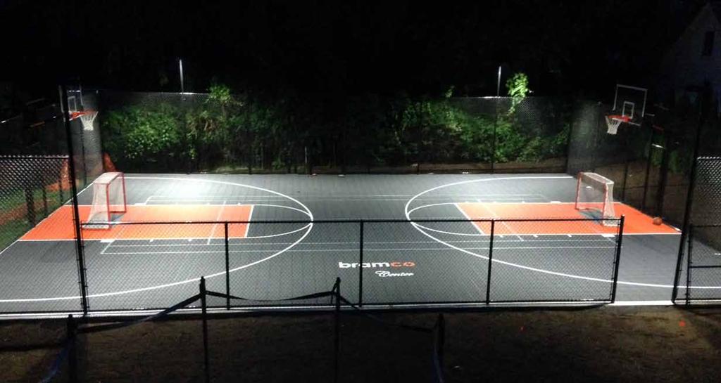


1 VERsacourt LED Light System Installation Instructions
 EXTENSION COLLAR BASE POLE EXTENSION POLE ANCHOR")
2 PART LIST TEE BAR ASSEMBLY LIGHT ASSEMBLY (hardware included) EXTENSION COLLAR BASE POLE EXTENSION POLE ANCHOR PAGE 1
3 REQUIRED TOOLS AND MATERIALS 1. Spade 2. Shovel 3. Wheelbarrow 4. Level 5. Tape Measure 6. Auger or Post Hole Digger 7. Water , 60 Lb. or 8-11, 80 lb. Bags of Dry Concrete Mix 9. Allen Wrenches - Various Sizes 10. Hammer 11. Wrenches - Various Sizes 12. Tape measure GROUND ANCHOR INSTALLATION BEFORE YOU BEGIN Contacting buried utilities may cause serious injury or death. Before you start digging, always contact your local One-Call system to help prevent personal injury, interruption of services, environmental accidents or job delays. Electric lines can shock or electrocute. Gas lines can rupture causing explosion or fire. Laser light in fiber optic cable can cause blindness. One-Call will notify participating utility companies of your proposed project. If you do not know the number for the local One-Call digging in your area, call the National One-Call at for this information. After being notified, utility companies will mark their underground facilities by using the following international marking codes: COLOR DEFINITION RED ELECTRIC YELLOW GAS, OIL, PETROLEUM ORANGE COMMUNICATION, TELEPHONE, TV BLUE POTABLE WATER GREEN/BROWN SEWER WHITE PROPOSED EXCAVATION PINK SURVEYING PAGE 2
4 Use the following guidelines when installing ground anchor into a hard-surfaced area: (See Image 2) Top of ground anchor to be 1-1/2 above the playing surface Top of ground anchor must be level in both directions across the mounting surface Anchor must be positioned with the hinge side of anchor toward area to be lighted or positioned as indicated on the concrete layout drawing supplied by VersaCourt Anchor to be positioned with hinge parallel with playing surface Distance from edge of hole made in playing surface to anchor to be no less than 6 unless indicated on concrete layout drawing supplied by VersaCourt Distance from bottom of ground anchor plate to concrete fill to be no less than 1-1/2 STEP 1 Once location of goal has been determined, locate center of ground anchor hole. STEP 2 Dig hole approximately 18 in diameter and deep. Use a spade, shovel, auger or post-hole digger. (See Image 1) Image 1 18 Diameter STEP 3 Locate and unpack ground anchor. Do not remove plastic plugs or hinge bolt STEP 4 Place 2-3 bags of concrete mix into hole; add water and stir. Follow concrete mix manufacturer s instructions for best results. Image 2 6 PLAYING SURFACE 1½ ANCHOR ELECTRICAL CONDUIT 18 Diameter PAGE 3
5 STEP 5 Install 3/4 PVC electrical conduit so that one end projects beyond the base plate and the other beyond the concrete in the hole. (see Image 2). The conduit should protrude beyond the base plate by 1. Before installing light base pole, caulk around conduit sealing it to the base plate. Caulking should be applied in a manner that will prevent water from running down into the base anchor. A silicone based caulk is recommended. Be sure to tape both ends of the conduit to keep the concrete out while filling the hole. Typical mounting is to position the anchor in center of hole with hinge side toward and parallel with playing surface. If the hinge cannot be located in this position, because of a fence or other obstruction, turn the hinge location so that the light pole can be raised and lowered unobstructed. IMPORTANT: As hole is filled with concrete mix, periodically place a level on top of anchor plate and check that it is level front-to-back and left to-right. Also check that the top of anchor is at correct height. Step 6 Continue filling hole with concrete mix until it is within 1.5 of anchor plate bottom. ASSEMBLING THE LIGHT IMPORTANT: Concrete must cure a minimum of 48 hours before attaching base pole to light anchor IMPORTANT: Safe assembly of the light pole requires three to four people in good physical condition and capable of lifting lbs each. IMPORTANT: Locate and familiarize yourself with all parts of the light before beginning assembly. STEP 1 Attach base pole to anchor at hinge point using the hinge bolt (3/8-16 x 5 ) and a 3/8 nut. Use the packaging material the base pole was in to lay the pole on to avoid scratching the finish. (See image 3) Image 3 HINGE BOLT PAGE 4
6 STEP 2 Place a mark 24 from one end of extension pole. The mark represents the minimum amount of the extension pole that must be inside the base pole. Slide the extension pole into the base pole and slide the extension collar over the extension pole. Set the height of the light by extending the inner pole to the desired location and locking the extension collar. Extension collar uses (4) 5/16 24 x 3/8 set screws to secure it to the extension pole. (See Image 4) IMPORTANT: A minimum of 24 of the extension pole must be inside the base pole. Height of LIGHT Maximum 20 Minimum: 12 Note: The maximum light spread will be achieved at maximum height Note: If this light pole is to be used as part of an adjustable net system, now is the time to install the brackets for the net support system. (see instructions included with adjustable net system) Image 4 Minimum 24 Overlap EXTENSION POLE EXTENSION COLLAR BASE POLE ANCHOR STEP 3 Attach Tee Bar to the extension pole. Lock Tee Bar into place with (2) 3/8-16 x ½ set screws. on pole. (See Image 5) Image 5 TEE BAR ASSEMBLY LOCKING SET SCREW PAGE 5
7 STEP 4 Attach the lights to the Tee Bar by sliding the Slipfitter Mount of the lights over the connection points of the Tee Bar and tightening the set screws. Wiring from the light fixtures will enter the tee bar through a hole inside the connection point and directly under the light fixture mount. (See Image 6) Final directional positioning or aiming of the lights can be completed after the light pole has been hinged to the vertical position. Image 6 LIGHT ASSEMBLY TEE BAR ASSEMBLY STEP 5 Run wiring connecting the two lights and down the light pole. If the light switch is to be mounted on the pole do this now and complete all wiring. After wiring is complete install the (2) plastic end caps. Run wires through the conduit in the ground anchor and finish connections to the wires in the light pole. Note: Each lamp can operate on the following single phase voltages 100V to 240V. Size the supply wire and any additional components accordingly. Note: It is advisable to have a local licensed electrician complete all wiring. PAGE 6
8 STEP 6 Stand the light pole upright. Tie a strap to the top of the base pole. With three people pushing and one person pulling on the strap, slowly move the light to the vertical position. While holding in place, install (4) ½ -13 x 1 ½ bolts and (4) ½ lock washers in the base plate and tighten. STEP 7 Aim the lights. With the use of an extension ladder, position the lamps so that they light the playing surface most effectively. FOR MORE INFORMATION You have now completed the installation process for your VersaCourt LED Light. If you would like to submit a picture of your finished project photos to info@versacourt.com If you encounter any issues during your installation process, feel free to call VersaCourt at for advice. We thank you for choosing VersaCourt. This installation manual is provided for informational purposes only to give the consumer basic understanding of the installation process for VersaCourt products. The following procedures are in accordance with VersaCourt LED Light installations. VersaCourt makes no warranty as to, and bears no liability for, the content or use of this installation manual. VersaCourt will not be held liable for any self-installed LED Lights. For self-installed LED Lights, owner assumes all responsibility and liability. VersaCourt representatives will, however, remain available for any questions you may have during your installation. PAGE 7
Phenom X SERIES X540 X660 X672 ADJUSTABLE HEIGHT GOAL SYSTEM. Installation. &Owners. Instructions
 Phenom X SERIES X540 X660 X672 ADJUSTABLE HEIGHT GOAL SYSTEM Installation &Owners Instructions I THANK YOU! Thank you and congratulations for purchasing a Proformance Hoops Goal - the finest basketball
Solar Powered TS1000 Installation Pictures. (Trench and Fill Method) City of Vallejo, CA
 City of Vallejo, CA") Solar Powered TS1000 Installation Pictures (Trench and Fill Method) City of Vallejo, CA 12/04/09 Page 1 Pre-installation Phase 1. Main system components arrive on one or more pallets. 2. Optional pole
Solar Powered TS1000 Installation Pictures (Trench and Fill Method) City of Vallejo, CA 12/04/09 Page 1 Pre-installation Phase 1. Main system components arrive on one or more pallets. 2. Optional pole
Conergy SolarFamulus II
 Conergy SolarFamulus II Installation manual www.conergy.com Table of Contents Table of Contents SolarFamulus II for universal use on flat roofs 1 Introduction 1 1.1 Short description 1 1.2 Intended use
GROUND MOUNT INSTALLATION MANUAL
 GROUND MOUNT INSTALLATION MANUAL Contents DISCLAIMER 1 CHECKLIST 2 1. ERECT BASe 3 2. CONNECT PIPES 3 3. PLACE RAILS 4 4. SECURE LUGS 4 5. CLAMP MODULES 5 DIAGONAL BRACES (OPTIONAL) 6 UNDER CLAMPS (OPTIONAL)
ROOF MOUNT KIT OWNERS MANUAL
 ROOF MOUNT KIT OWNERS MANUAL Made in the USA by: Primus Wind Power, Inc. 938 Quail St. Lakewood, CO 80215 Phone: (303) 242-5820 www.primuswindpower.com AIR is a trademark of Primus Wind Power, Inc. ROOF
INSTALLATION MANUAL RECTANGULAR COLUMN
 INSTALLATION MANUAL RECTANGULAR COLUMN Model # 5502 OVERVIEW The Rectangular Column is a UL-listed, multi-sided, vertical hospital modular service assembly. This system uses vertical and/or horizontal
ROOF MOUNT KIT OWNERS MANUAL
 ROOF MOUNT KIT OWNERS MANUAL Made in the USA by: Southwest Windpower, Inc. 1801 W. Route 66 Flagstaff, Arizona 86001 Phone: (928) 779-9463 Fax: (928) 779-1485 E-mail: info@windenergy.com Web: www.windenergy.com
FITNESS PLAYGROUND ITEM NO: 8010
 FITNESS PLAYGROUND ITEM NO: 8010 OWNER S MANUAL CAUTION: This unit is designed to be used safely by up to 4 children between the ages of 3 years to 8 years old with a maximum weight of 100 pounds (45.4
OPO-SHORT Installation Instructions Manual Version
 10200 South Kedzie Avenue Evergreen Park, IL 60805 800.499.0400 708.499.0400 Fax 708.499.4620 OPO-SHORT Installation Instructions Manual Version OPO-1S, OPO-3S, OPO-4S PreSell Main Board (shown as Standard
INSTALLATION MANUAL SURFACE-MOUNTED HEADWALL
 INSTALLATION MANUAL SURFACE-MOUNTED HEADWALL Model # Series 7200-S Top Mounting Plate Electrical Junction Box Located Behind Removable Upper Panel Medical Gas Connections Lower Mounting Plate OVERVIEW
OWNER S MANUAL SERIES MDS-96-BK, SM, DR
 SERIES MDS-96-BK, SM, DR OWNER S MANUAL Introduction... 1 Bill of Materials... 2 Assembly Instructions. 3 Warranty....12 IMPORTANT NOTES, WARNINGS AND SAFETY INSTRUCTIONS Ensure that all employees understand
GroundTrac. Installation Manual
 APPLICATION: The GroundTrac system is designed with a minimum amount of installed footings at greatly reduced labor. The system integrates with ordinary 1-1/2 schedule #40 galvanized water pipe. This ground
Electric Service Handbook
 Electric Service Handbook Revised August 2017 Contact Information Telephone (253): Electrical Inspection Office 502-8277 7:30 am - 4:30 pm Electrical Inspectors Area Map on Website 7:30 am - 8:30 am Automated
Aegis Heavy Capacity 20K Floor Scale. MODEL: 6200 Series. Installation Manual
 Installation Manual Aegis Heavy Capacity 20K Floor Scale MODEL: 6200 Series Copyright 1997-2014 Fairbanks Scales, Inc. Revision 3 50637 All Rights Reserved 07/14 Aegis Heavy Capacity 20K Floor Scale Model:
Instructions for 12 and 15 IGT systems (12 pictured)
") Instructions for 12 and 15 IGT systems (12 pictured) Step 1: IGT Site Preparation Site Location Several factors must be considered when choosing the site for your new In-Ground Trampoline (IGT) system.
Instructions for 12 and 15 IGT systems (12 pictured) Step 1: IGT Site Preparation Site Location Several factors must be considered when choosing the site for your new In-Ground Trampoline (IGT) system.
OWNER S MANUAL SERIES MDS-96-BK, SM, DR
 VESTIL MANUFACTURING CORP. 2999 N. Wayne St., Angola, IN 46703 Ph: 260-665-7586 Fax: 260-665-1339 E-mail: sales@vestil.com Website: www.vestil.com SERIES MDS-96-BK, SM, DR OWNER S MANUAL Introduction...
SpaVault TM Installation Guide for Bullfrog Spas (7-10 x 7-10 x 38 )
") SpaVault TM Installation Guide for Bullfrog Spas (7-10 x 7-10 x 38 ) WARNING - When unpacking SpaVault, DO NOT discard styrofoam pieces, these are not packaging materials. Step 1 Excavation Important:
SpaVault TM Installation Guide for Bullfrog Spas (7-10 x 7-10 x 38 ) WARNING - When unpacking SpaVault, DO NOT discard styrofoam pieces, these are not packaging materials. Step 1 Excavation Important:
FIXED CEILING COLUMN. Installation Manual FIXED CEILING COLUMN
 FIXED CEILING COLUMN Installation Manual FIXED CEILING COLUMN INTRODUCTION Location, sequence of services and orientation of Surgical Ceiling Columns are specified on the building plans. Be certain installation
PV Mounting System 2703 SERIES 200 UL GROUND MOUNT SYSTEM. SnapNrack Residential PV Mounting Systems Code Compliant Installation Manual
 PV Mounting System 2703 SERIES 200 UL GROUND MOUNT SYSTEM SnapNrack Residential PV Mounting Systems Code Compliant Installation Manual Series 200 UL Introduction Series 200 UL Introduction SnapNrack Series
A Collaborative Program of Arbor Day Foundation and Dimensions Educational Research Foundation. Tube Drums #7000. Assembly Instructions
 A Collaborative Program of Arbor Day Foundation and Dimensions Educational Research Foundation Tube Drums #7000 Assembly Instructions Please open and inspect all items upon receipt. If you have any questions
Linear Drainage Z886. Perma-Trench. Installation Instructions. 100mm Clear Opening
 Linear Drainage Z886 100mm Clear Opening Perma-Trench Installation Instructions Z886 Tools Required Tape Measure Phillips Head Screwdriver Hammer Utility Knife Marker Cordless Drill Reciprocating Saw Ear
Platform stair lift PLG7
 Platform stair lift PLG7 ORIGINAL-user manual Part 2: Assembly Instruction English Version 2.00 ASCENDOR GMBH Drautendorf 48 4174 Niederwaldkirchen Austria Tel.: +43 7231 40040 Fax: +43 7231 40040-590
Bravo Platform Unpacking Guide
 This guide describes how to unpack the Bravo device from the shipping carton. Depending on the order, the shipment can include additional packages for the Bravo utilities, pipetting head, computer, and
Structural Cantilever Installation Manual
 Structural Cantilever Installation Manual 944 Fisher St. Houston, TX 77018 ~ 713-957-1111 Table of Contents Assembly... 3 Warnings... 3 Tools... 3 Components... 4 Begin Assembly... 5 Step #1: Check all
V 2.0 ASSEMBLY GUIDE. TS Platform Scale Series 2
 V 2.0 ASSEMBLY GUIDE Series 2 TABLE OF CONTENTS OVERVIEW General Specifications...1 Cautions and Disclaimers...1 Contents of Kit...1 Tools Required For Assembly...2 Time Required to Assemble...2 ASSEMBLING
INSTALLATION GUIDE PLEASE READ ENTIRE INSTRUCTION MANUAL BEFORE PROCEEDING!
 DURA - TRENCH INSTALLATION GUIDE This guide is intended to aide in the installation of Dura-Trench systems. There are many different applications and situations for the use of this product and the installation
STP Mount Series. Installation Manual. STP-LSCR-MAN 2017 Edition v1.0. For models: STP-SCR/045 STP-SCR/060 STP-SCR/070 STP-LCR/090 STP-LCR/120
 Installation Manual STP-LSCR-MAN 2017 Edition v1.0 For models: STP-SCR/045 STP-SCR/060 STP-SCR/070 STP-LCR/090 STP-LCR/120 Table of Contents Introduction... 1 Customer Support... 1 Tools Required... 2
Agilent 1220 Infinity LC Mobile Upgrade Kit
 Agilent 1220 Infinity LC Mobile Upgrade Kit User Manual Agilent Technologies Notices Agilent Technologies, Inc. 2012 No part of this manual may be reproduced in any form or by any means (including electronic
INSTALLATION GUIDE. Tranquil Mount Model: TMO100A. Support 40" to 65" Screens Load Capacity: 16.5~70.5 lbs (7.5~32 kg) Non-VESA compatible
 Non-VESA compatible") ISTALLATIO GUIDE Tranquil Mount Model: TMO100A Support 0" to 65" Screens Load Capacity: 16.5~70.5 lbs (7.5~32 kg) on-vesa compatible 100mm x 100mm 120mm x 180mm 200mm x 100mm 200mm x 200mm 200mm x 300mm
ISTALLATIO GUIDE Tranquil Mount Model: TMO100A Support 0" to 65" Screens Load Capacity: 16.5~70.5 lbs (7.5~32 kg) on-vesa compatible 100mm x 100mm 120mm x 180mm 200mm x 100mm 200mm x 200mm 200mm x 300mm
INSTALLATION GUIDE. Tranquil Mount Model: TMO100A. Support 40" to 65" Screens Load Capacity: 16.5~70.5 lbs (7.5~32 kg) Non-VESA compatible
 Non-VESA compatible") ISTALLATIO GUIDE Tranquil Mount Model: TMO100A Support 0" to 65" Screens Load Capacity: 16.5~70.5 lbs (7.5~32 kg) on-vesa compatible 200mm x 200mm 200mm x 300mm 300mm x 300mm 00mm x 200mm 00mm x 300mm
ISTALLATIO GUIDE Tranquil Mount Model: TMO100A Support 0" to 65" Screens Load Capacity: 16.5~70.5 lbs (7.5~32 kg) on-vesa compatible 200mm x 200mm 200mm x 300mm 300mm x 300mm 00mm x 200mm 00mm x 300mm
Foundation Manual. Part Number: Version: Updated: July 5, S. Meadows Pkwy. A-9, #329 Reno, NV
 Foundation Manual Part Number: 150002 Version: 1.22 Updated: July 5, 2009 748 S. Meadows Pkwy. A-9, #329 Reno, NV 89521 775-831-9463 www.mariahpower.com July 2009, Mariah Power, All Rights Reserved Dear
HALSEY TAYLOR OWNERS MANUAL Classic TM Series Barrier-Free Water Coolers Refrigerated Fountains with Back Panel
 HALSEY TAYLOR OWNERS MANUAL Classic TM Series BarrierFree Water Coolers Refrigerated Fountains with Back Panel Figure HTERQ Figure HTSRQ Figure 3 HTSERQ Figure HTESRQ Figure 3 Model HTERQ HTSRQ HTSERQ
PLEASE READ ENTIRE INSTRUCTION MANUAL BEFORE PROCEEDING!
 INSTALLATION GUIDE This guide is intended to aide in the installation of Dura-Trench systems. There are many different applications and situations for the use of this product and the installation procedures
Model # BARK /26/2012 Page 1 of 5
 Model # BARK-430 6/26/2012 Page 1 of 5 6/26/2012 Page 2 of 5 1675 Locust Street Red Bud, IL 62278 Phone: 618-282-8200 Fax: 618-282-8202 WARRANTY & TERMS WARRANTY: 5 Year Limited Warranty on Thermoplastic/Canine
Standard Duty Cantilever Rack Installation and Assembly Guide
 Standard Duty Cantilever Rack Installation and Assembly Guide Steel King Industries, Inc. 2700 Chamber St Stevens Pont, WI 54481 (800) 826 0203 www.steelking.com info@steelking.com ASSEMBLY INSTRUCTIONS:
General Guidelines. Tools Required. Instructions for Part # SC500-AF. Safety
 Instructions for Part # SC500-AF General Guidelines It is the user s responsibility to read and follow all instructions. Keep these instructions with the product at all times and review before each use.
ALPINE PATIO COVER INSTALLATION INSTRUCTIONS
 ALPINE PATIO COVER INSTALLATION INSTRUCTIONS Contact us at: 1-800-851-0865 or www.americana.com Before You Begin: Consult your local building department for any required permits You may be required to
OZARK PATIO COVER INSTALLATION INSTRUCTIONS
 OZARK PATIO COVER INSTALLATION INSTRUCTIONS Contact us at: 1-800-851-0865 or www.americana.com Before You Begin: Consult your local building department for any required permits You may be required to obtain
General Guidelines. Tools Required. Safety. Deluxe Steel Folding Scooter & Wheelchair Carrier Instructions for Part # SC500-V3
 Deluxe Steel Folding Scooter & Wheelchair Carrier Instructions for Part # SC500-V3 General Guidelines It is the user s responsibility to read and follow all instructions. Keep these instructions with the
Preference Slimline 5537 Utility Console I NSTALLATION GUIDE
 Preference Slimline 5537 Utility Console I NSTALLATION GUIDE WARNING Failure to install the 5537 as described in this installation guide may cause the unit to collapse, resulting in serious injury to personnel.
Basic Service. This Section provides information regarding a. Introduction
 Basic Service Introduction This Section provides information regarding a new electric Basic Service for a single phase service less than or equal to 400 amps, and a three phase service less than 50kW.
the fixed post kit product manual for folding clotheslines
 the fixed post kit product manual for folding clotheslines 2 Introduction Pack Contents and Installation 3 Congratulations Congratulations on the purchase of your new Hills Folding Clothesline Post Kit.
FORM FOOTWALL. FORM FOOTWALL (floating) (floating) Installation Manual
 (floating) Installation Manual") FORM FOOTWALL (floating) Installation Manual FORM FOOTWALL (floating) OVERVIEW The Form is a UL-listed configurable footwall system. This system can include any combination of base cabinets, upper cabinets,
FORM FOOTWALL (floating) Installation Manual FORM FOOTWALL (floating) OVERVIEW The Form is a UL-listed configurable footwall system. This system can include any combination of base cabinets, upper cabinets,
INSTALLING A POUR-IN-PLACE DOCK LEVELER (EH & RR)
") INSTALLING A POUR-IN-PLACE DOCK LEVELER (EH & RR) Part A: Prepare the Site & Make the Floor 1.) Prepare (concrete) dock wall and pit floor as shown in the diagrams. Pit floor should taper from back to
INSTALLING A POUR-IN-PLACE DOCK LEVELER (EH & RR) Part A: Prepare the Site & Make the Floor 1.) Prepare (concrete) dock wall and pit floor as shown in the diagrams. Pit floor should taper from back to
LINEAR DRAINAGE. Z886 Perma-Trench. 6" Perma-Trench Installation Instructions
 LINEAR DRAINAGE Z886 Perma-Trench 6" Perma-Trench Installation Instructions Z886 Accessories 6" [152MM] WIDE TRENCH DRAIN SYSTEM Below are the components of the Z886 trench drain typical to an installation.
INSTALLATION MANUAL. FOOTWALL/SINKWALL (floor mount)
") INSTALLATION MANUAL FOOTWALL/SINKWALL (floor mount) OVERVIEW The Form is a UL-listed configurable footwall/sinkwall system. This system can include any combination of base cabinets, upper cabinets, wardrobes,
INSTALLATION MANUAL FOOTWALL/SINKWALL (floor mount) OVERVIEW The Form is a UL-listed configurable footwall/sinkwall system. This system can include any combination of base cabinets, upper cabinets, wardrobes,
FORM HEADWALL. FORM HEADWALL (floating) (floating) Installation Manual
 (floating) Installation Manual") FORM HEADWALL (floating) Installation Manual FORM HEADWALL (floating) OVERVIEW The Form is a UL-listed configurable headwall system. This system includes multiple horizontal equipment channels integrated
FORM HEADWALL (floating) Installation Manual FORM HEADWALL (floating) OVERVIEW The Form is a UL-listed configurable headwall system. This system includes multiple horizontal equipment channels integrated
POOL STEP INSTRUCTIONS (NE1087WH)
") POOL STEP INSTRUCTIONS (NE1087WH) 6492 The sequence of the instructions may vary at points depending on the type of step system that you have purchased. If there are different instructions for your system,
POOL STEP INSTRUCTIONS (NE1087WH) 6492 The sequence of the instructions may vary at points depending on the type of step system that you have purchased. If there are different instructions for your system,
TETON PATIO COVER INSTALLATION INSTRUCTIONS
 TETON PATIO COVER INSTALLATION INSTRUCTIONS Contact us at: 1-888-442-2928 or www.americana.com Before You Begin: Consult your local building department for any required permits You may be required to obtain
Modular Coldroom Installation Manual
 Modular Coldroom Installation Manual May 2005 Disclaimer: The information contained in this installation guide is provided "as is". Bromic Pty Ltd does not warrant the accuracy, adequacy or completeness
INSTALLATION AND MAINTENANCE GUIDE SECTION 3 HANDRAIL DECK LIGHTS
 INSTALLATION AND MAINTENANCE GUIDE SECTION 3 HANDRAIL DECK LIGHTS CONTENTS DECKING AND DRYSPACE RAILING SYSTEMS HANDRAIL DECK LIGHTS Installing TimberTech 04 Tools Required 04 Read Before You Start 05
Inigo Console Table INSTALLATION INSTRUCTIONS P74300, P A Page 1 of 5
 P74300, P74301 Page 1 of 5 THANK YOU FOR CHOOSING KALLISTA We appreciate your commitment to Kallista quality products. Please take a moment to review this manual before you install your Kallista product.
Safety on Heights: Our Policy
 11/17/14 Safety on Heights: Our Policy Only volunteers over the age of 18 are allowed to work on heights of more than six feet off the ground. This includes all work on scaffolds. Only volunteers who are
Rough-in frame and flush-mount panel installation instructions
 Welch Allyn, Inc. 3 State Street Road Skaneateles Falls, NY 33 USA Rough-in frame and flush-mount panel installation instructions 726080 DIR 8002869 Ver. A Revised 206- The Welch Allyn In-Floor Scale models
FORM HEADWALL. FORM HEADWALL (floor mount) (floor mount) Installation Manual
 (floor mount) Installation Manual") FORM HEADWALL (floor mount) Installation Manual FORM HEADWALL (floor mount) OVERVIEW The Form is a UL-listed configurable headwall system. This system includes multiple horizontal equipment channels integrated
FORM HEADWALL (floor mount) Installation Manual FORM HEADWALL (floor mount) OVERVIEW The Form is a UL-listed configurable headwall system. This system includes multiple horizontal equipment channels integrated
INSTALLATION INSTRUCTIONS FOR ELECTRICAL CONTRACTORS
 INSTALLATION INSTRUCTIONS FOR ELECTRICAL CONTRACTORS Rev. 1.5 1.10.13 Toll free (800) 288-6000 or www.hubbell-wiring.com P a g e 0 IMPORTANT SAFETY INSTRUCTIONS SAVE THESE INSTRUCTIONS WARNING- When using
ITEM L-119 AIRPORT OBSTRUCTION LIGHTS DESCRIPTION
 SECTION 74 AIRPORT OBSTRUCTION LIGHTS (FAA L-119) 74-1 GENERAL The Contractor shall perform all work required by the plans and specifications for construction of obstruction lights in accordance with the
ASSEMBLY INSTRUCTIONS RESIDENTIAL SOLUTION CROSSRAIL GROUND MOUNT SYSTEM USA
 ASSEMBLY INSTRUCTIONS RESIDENTIAL SOLUTION CROSSRAIL GROUND MOUNT SYSTEM USA TABLE OF CONTENTS TABLE OF CONTENTS SAFETY REGULATIONS MATERIALS REQUIRED ASSEMBLY ENGINEERING DRAWINGS TERMS AND CONDITIONS
To Contact PS DOORS:
 MODELS Stainless Steel (SS) Powder Coat Yellow (PCY) Hot Dipped Galvanized (GAL) TABLE OF CONTENTS PAGE Warranty Information General Paired LSG Information Installing the Support Channels 3 Installing
Axiom. SURFACE MOUNTED ARRAY Patient Headwall. Installation Guidelines. Installation Instructions.
 Axiom www.hsiheadwalls.com SURFACE MOUNTED ARRAY Patient Headwall Installation Instructions Installation Guidelines Tel: 925.427.7800 Fax: 925.427.0800 support@hsiheadwalls.com Hospital Systems Inc. 750
Drag Chain Conveyor Installation and Operation Manual
 Drag Chain Conveyor Installation and Operation Manual Material Handling Equipment Sales, Incorporated 310 S. Section Line Rd Delaware, OH 43015 Phone: (989) 430-4005 Fax: (740) 363-9004 WARRANTY MATERIAL
TECHNICAL ASSISTANCE TOLL FREE TELEPHONE NUMBER TECHNICAL ASSISTANCE FAX:
 ACORN SAFETY P.O. BOX 3527 CITY OF INDUSTRY, CA 91744-0527 UNITED STATES OF AMERICA WWW.ACORNSAFETY.COM INSTALLATION, OPERATION AND MAINTENANCE INSTRUCTIONS COMBINATION STATIONS MODELS S1330-FPB/S1340-FPB/S2330-FPB/S2340-FPB/2330-FPB-ASP
ALPINE PATIO COVER INSTALLATION INSTRUCTIONS
 ALPINE PATIO COVER INSTALLATION INSTRUCTIONS Contact us at: 1-800-851-0865 or www.americana.com Before You Begin: Consult your local building department for any required permits You may be required to
General Safety Information
 TM General Safety Information To reduce the risk of death, personal injury or property damage from fire, electric shock, falling parts, cuts/abrasions, and other hazards read all warnings and instructions
Model # 800SM-PS3. 8/3/2016 Page 1 of 8
 Model # 800SM-PS3 8/3/2016 Page 1 of 8 /3/2016 Page 2 of 8 1675 Locust Street Red Bud, IL 62278 Phone: 618-282-8200 Fax: 618-282-8202 WARRANTY & TERMS WARRANTY: 5 Year Limited Warranty on Thermoplastic
1.0. Post Install Kit. For Use With All Vinyl Railing BOM V1 1/13. Owner's Manual. Assembly and Installation Instructions.
 Post Install Kit Assembly and Installation Instructions PLEASE READ OWNER'S MANUAL COMPLETELY BEFORE ASSEMBLING YOUR POST INSTALL KIT. For Use With All Vinyl Railing 34106837BOM V1 1/13 Owner's Manual
INSTALLATION GUIDE. 4-Post Lift. Model United States. United Arab Emirates. Egypt.
 4-Post Lift INSTALLATION GUIDE United States 17779 Main Street Suite C Irvine, CA 92614 USA Tel: +1(949) 333-3800 Fax: +1(949) 333-3804 United Arab Emirates Model 46614 P.O. Box 121971 Saif Zone A2-032
ANY SPECIFICATION DRAWINGS OR DATED PRIOR TO SEPTEMBER 2015 WILL NOT BE HONORED.
 November 30, 2015 Dear STEMC Member and Contractors, Over the years, STEMC has made many changes to its member requirements for new services and specifications associated with those requirements. As a
OmniFlex 300 Plus Installation Instructions
 OmniFlex 300 Plus Installation Instructions IMPORTANT PortaFab advises a thorough reading of these instructions before beginning installation. INTRODUCTION Instructions should be read thoroughly and cross-referenced
General Guidelines. Tools Required. Steel Folding Scooter & Wheelchair Carrier Instructions for Part # SC400-V2. Safety
 Steel Folding Scooter & Wheelchair Carrier Instructions for Part # SC400-V2 General Guidelines It is the user s responsibility to read and follow all instructions. Keep these instructions with the product
GC-X360S-W GC-X360S-B
 GC-X360S-W GC-X360S-B Game Console Security Cover for Xbox 360S 1 date:01/22/13 #:125-9401 WARNING ENG - This product was designed to be installed on wood stud, solid concrete or cinder block walls. Before
Model m x 1.98 m NPRM with Roof Pads For 1.2 m Antenna Systems
 Installation Instructions 800026-0 Model 60057-03.98 m x.98 m NPRM with Roof Pads For.2 m Antenna Systems ASC Signal Corporation 35 Industrial Park Drive Smithfield, NC 27577 USA Telephone: +-99-934-97
CONSTRUCTION SPECIFICATION FOR POLE ERECTION
 ONTARIO PROVINCIAL STANDARD SPECIFICATION METRIC OPSS 615 NOVEMBER 2006 CONSTRUCTION SPECIFICATION FOR POLE ERECTION TABLE OF CONTENTS 615.01 SCOPE 615.02 REFERENCES 615.03 DEFINITIONS - Not Used 615.04
Zurn Z886. 6" Perma-Trench. Installation Instructions
 Zurn Z886 6" Perma-Trench Installation Instructions Z886 Accessories 6" [152mm] Wide Trench Drain System Below are the components of the Z886 trench drain typical to an installation. Check your order to
Universal Elevator Mount Owners Manual
 REQUIRED TOOLS AND MATERIALS: 2 Capable Adults Universal Elevator Mount Owners Manual 1-00-spalding Carpenter s Level 15 Tape Measure Pencil Adult Assembly Required. This manual, accompanied by sales receipt,
Operator s Manual for Morse Kontrol-Karrier with Spark Resistant Parts and Air Power Tilt
 Contents Page Receiving Procedures.................... 1 Warranty............................. 1 Safety Information..................... 1-2 Machine Description................... 2 Assembly Instructions..................
SENTINEL BARRIER - GENERAL INSTALLATION GUIDELINES
 SENTINEL BARRIER - GENERAL INSTALLATION GUIDELINES Safety Precautions in the Excavation of a Sentinel Wedge take all necessary steps to make sure the pit is secured. Follow all OSHA requirements for digging
H 12 Heavy Duty Modern Tripod 8 Seat Swing Heavy Duty Hangers
 Page 1 IMPORTANT Please retain this instruction sheet in your files. It contains important replacement parts information. All equipment should be installed in accordance with these instructions. It is
DETAIL INSTRUCTION No. 1
 BEFORE BEGINNING INSTALLATION, PLEASE READ THROUGH ALL INSTRUCTIONS. Uncrate shipment and check against packing list to insure all materials are included before beginning installation. If any discrepencies
OVERHEAD SERVICES - SECONDARY
 OVERHEAD SERVICES - SECONDARY Contents - Overhead Services... O-1 General Requirements for Overhead Service... O-2 Names of Parts for Overhead Service... O-3 Service Attachment on an Unguyed Service Mast...
FitTech UP166F CHEST PRESS (FOOTING) UP166I CHEST PREES (IN GROUND) UP166S CHEST PRESS (SURFACE)
 UP166I CHEST PREES (IN GROUND) UP166S CHEST PRESS (SURFACE)") CHEST PRESS BASE COVER DESCRIPTION FOOTBUCK WELD ASSEMBLY HARDWARE COMPLETE HARDWARE COMPLETE HARDWARE COMPLETE /" ANCHOR ROD 3/" x " HEX HEAD CAP SCREW 3/" WEDGE ANCHOR 3/" ANCHOR BOLT 3/" FLATWASHER
CHEST PRESS BASE COVER DESCRIPTION FOOTBUCK WELD ASSEMBLY HARDWARE COMPLETE HARDWARE COMPLETE HARDWARE COMPLETE /" ANCHOR ROD 3/" x " HEX HEAD CAP SCREW 3/" WEDGE ANCHOR 3/" ANCHOR BOLT 3/" FLATWASHER
Installation Guide. PrivacyShield Outdoor Enclosure
 Installation Guide PrivacyShield Outdoor Enclosure Table of Contents 1.0 Introduction... 2 2.0 Materials, Delivery & Tools... 2 3.0 Layout and Post Locations. 3 4.0 Foundations... 5 5.0 PVC Installation....
PRODUCT INFORMATION Dero Hoop Rack
 PRODUCT INFORMATION Dero Hoop Rack 2946 Larimer St. Denver, CO 80205 303-295-1100 / 800-373-7693 FAX 303-295-2464 Email info@snyderequipment.com www.snyderequipment.com H O O P R A C K The Hoop Rack is
Risk of fire and electrical shock. DISCONNECT POWER AT ELECTRICAL PANEL before installing or servicing this product.
 INSTALLATION INSTRUCTIONS RAIL 2 RM2D T-BAR LED NOTE: The following instructions provide general guidelines for product installation. For additional information consult the applicable electrical codes
FPM115MF ( <02>)
") () Thank you for choosing the VuePoint wall mount. The VuePoint wall mount is designed to support a monitor sized up to 37 (94 cm) and weighing up to 27 kg (60 lbs). Hardware for multiple mounting configurations
() Thank you for choosing the VuePoint wall mount. The VuePoint wall mount is designed to support a monitor sized up to 37 (94 cm) and weighing up to 27 kg (60 lbs). Hardware for multiple mounting configurations
Installation Instructions
 Installation Instructions Dynarail Safety Ladder System Corrosion Resistant Nonconductive Fire Retardant High Strength-To-Weight Ratio Long, Low Maintenance Life Meets OSHA, BOCA & Other Building Code
Installation Instructions/Operation and Maintenance Manual. Models PLG-60 PLG-72. PS DOORS Contact Information. Website psdoors.
 Rev. 091416 Pallet Gate Installation Instructions/Operation and Maintenance Manual Models PLG-60 PLG-72 Table of Contents Product Information...2 Installation Instructions...3 Operation...6 Inspection
A EN ROUND STORAGE SILO. Ø480cm, Ø560cm, Ø640cm, Ø720cm ASSEMBLY AND USER MANUAL. ARSKAMETALLI LTD
 A70-1001-EN-201805 ROUND STORAGE SILO Ø480cm, Ø560cm, Ø640cm, Ø720cm ASSEMBLY AND USER MANUAL ARSKAMETALLI LTD www.arskametalli.fi CONTENTS Introduction Delivery information EU Declaration of Conformity
FLO-THRU ACCESSORIES Above are some of the trench drain components typical to an installation. Double check your order to ensure that you have all com
 Z-882 12 PERMATRENCH TM ZURN INDUSTRIES, INC., FLO-THRU DIV., 2855 Girts Road, Jamestown, NY 14701 Phone: 716/665-1132, Fax: 716/665-1135, World Wide Web: www.zurn.com In Canada: ZURN INDUSTRIES LIMITED,
EASY RIDER (MUSTANG) EASY RIDER (PONY) EASY RIDER (ZEBRA) EASY RIDER (BRONCO)
 EASY RIDER (PONY) EASY RIDER (ZEBRA) EASY RIDER (BRONCO)") Page 1 * IMPORTANT * PLEASE RETAIN THIS INSTRUCTION SHEET IN YOUR FILES. IT CONTAINS IMPORTANT REPLACEMENT PARTS INFORMATION. ALL EQUIPMENT SHOULD BE INSTALLED IN ACCORDANCE WITH THESE INSTRUCTIONS. IT
Page 1 * IMPORTANT * PLEASE RETAIN THIS INSTRUCTION SHEET IN YOUR FILES. IT CONTAINS IMPORTANT REPLACEMENT PARTS INFORMATION. ALL EQUIPMENT SHOULD BE INSTALLED IN ACCORDANCE WITH THESE INSTRUCTIONS. IT
MODEL 285A-HD Heavy-Duty Forklift-Karrier Operator s Manual for Morse Heavy-Duty Forklift-Karrier Model 285A-HD
 Contents Page Receiving Procedures.................... 1 Warranty............................. 1 Safety Information..................... 1-2 Machine Description................... 3-4 Operating Instructions....................
E-Series Installing E-Series U Cabinet
 E-Series Installing E-Series 3040 40U Cabinet September 2018 215-13048_A0 doccomments@netapp.com Table of Contents 3 Contents Overview and specifications... 4 Cabinet features... 4 Power requirements
COPYRIGHT 2001 BY: GAMETIME REVISED: 08/09/01
 COPYRIGHT 2 BY: GAMETIME REVISED: 8/9/ 627 FITKID PARALLEL BAR NOTE: 627 2'-6" PARALLEL BAR 628 3' PARALLEL BAR 629 3'-" PARALLEL BAR 63 3'-6" PARALLEL BAR 63 3'-" PARALLEL BAR 632 '-2" PARALLEL BAR 633
Linear Drainage ZF806 ZF812
 Linear Drainage ZF806 ZF812 Fiberglass Trench Installation Instructions ZF806 Accessories 6" [152mm] Wide Fiberglass Trench Drain System Below are some of the ZF806 trench drain components typical to an
Guy cable tower for WTGS. Installation guide for tower & foundation
 for WTGS Installation guide for & foundation Warning: The guide has been carefully checked by engineers of Yangzhou Shenzhou Wind-driven Generator Co.,Ltd. Please excuse from specification alterations
Instruction Manual TWISTLOCK SAND VOLLEYBALL SOCKETS SVB23/SVB27
 Instruction Manual TWISTLOCK SAND VOLLEYBALL SOCKETS Customer Service (800) 247-7668 SVB23/SVB27 P A R T S L I S T Item Qty Description Item Qty Description A 1 Sand Volleyball Socket (3 or 4 ) B 1 Twistlock
Installation. Smart-UPS VT in Parallel kva 380/400/415 V 208/220 V 200/208 V
 Installation Smart-UPS VT in Parallel 10-40 kva 380/400/415 V 208/220 V 200/208 V Contents Safety... 1 IMPORTANT SAFETY INSTRUCTIONS - SAVE THESE INSTRUCTIONS.............................. 1 Prepare for
H07 H09. BENCH FUME HOOD with Combination Sash. Fume Hoods. Installation Instructions. 48"- 60"- 72"- 96" long
 Installation Instructions Supreme Air BENCH FUME HOOD with Combination Sash H07 H09 S T Y L E Fume Hoods 48"- 60"- 72"- 96" long Publication No. IIH07-SA 07/06 Part Number: IMAN-H07 FUME HOOD END PANEL