PLANNING AND DESIGN PARAMETERS BRIDGE STRUCTURES. Engr. Ericson Mammag Feasibility Study Preparation CHARM2 Project
|
|
|
- Beverley Hodges
- 5 years ago
- Views:
Transcription
1 PLANNING AND DESIGN PARAMETERS BRIDGE STRUCTURES Engr. Ericson Mammag Feasibility Study Preparation CHARM2 Project
2 KEY ELEMENTS IN RURAL INFRA Planning & Design Bridges Potable Communal Small Water Roads And Water Irrigation Impounding Culverts System Project Project General Design Concept X X X X X Alignment Design Horizontal and Vertical X Hydrology and Drainage X X X X X Geology and Hydrogeology O X X O X Geotechnical and Foundation Design X X O X X Hydraulic Design O X X X X Structural Engineering O X O O X Quantities and Cost X X X X X Implementation Schedule X X X X X Environmental Concerns O O O X X Institutional Requirements O O X X X Electrical and/or Mechanical Aspects O O O O X X Critical/essential element of review required O - Necessary but may not be essential
3 BRIDGES Elements of Bridge Structure Bridge and Culverts Bridge Nomenclature Classification of Bridges by Materials Classification of Bridges by Structural System
4 Elements of Bridge Structure
5 BRIDGES Bridge Location Waterways Site Data Hydrologic Analysis Hydraulic Analysis Pier Spacing, Orientation and Type Width of waterway and sidewalk Clearances Railings, Signages and Safety Devices
6 Bridge Basic Components DECK SUPERSTRUCTURE ABUTMENT (part of the substructure) PIER (part of the substructure)
7 maximum flood ws level river cross-section bridge approach clearance, 1.0 m or 1.5 m bridge girder bridge approach adjusted flood ws level original river cross-section local scour; around bridge piers river cross-section, general scour
8 maximum flood ws level SUPERSTRUCTURE river cross-section bridge approach clearance, 1.0 m or 1.5 m bridge girder bridge approach adjusted flood ws level original river cross-section local scour; around bridge piers PIER ABUTMENT river cross-section, general scour SUBSTRUCTURE
9 STANDARD MS TRUCK V = VARIABLE SPACING m TO 9.0m INCLUSIVE. SPACING TO BE USED IS THAT WHICH PRODUCES MAXIMUM STRESSES. CLEARANCE AND LOAD LANE WIDTH 3.00 m MS 18 MS KN 27 KN 4.27 m 144 KN 108 KN V 144 KN 108 KN CURB 0.1 W 0.4 W 0.4 W 0.60 m 1.80 m 0.60 m 0.1 W 0.4 W 0.4 W
10 APPLICABLE TYPES OF CONCRETE DECK 1. RC - SLAB TYPE SPAN LENGTH (M) HEIGHT / SPAN L/20 2. RC - HOLLOW SLAB 3. RC - T-BEAM 4. PC HOLLOW (Pretension) L/20 L/15 L/14 5. PC I-BEAM (Pretension) 6. PC T-BEAM (Pretension) 7. PC I-BEAM (Post) 8. PC T-BEAM (Post) 9. SIMPLE BOX GIRDER L/15 L/15 L/16 L/17.5 L/20
11 APPLICABLE TYPES OF STEEL DECK TYPE SPAN LENGTH (M) HEIGHT / SPAN 1. STEEL I-BEAM (Non Comp.) 0 10 L/20 2. STEEL I-BEAM (Comp.) 6 13 L/20 3. SIMPLE PLATE GIRDER 4. CONTINUOUS PLATE GIRDER L/15 L/14 5. SIMPLE COMP. GIRDER L/15 6. SIMPLE BOX GIRDER L/15 7. CONTINUOUS COMP. GIRDER L/16 8. CONTINUOUS BOX GIRDER 9. SIMPLE TRUSS L/17.5 L/20
12 Bridge Sub-structure Abutment a substructure which supports the end of a single span or extreme end of a multi-span superstructure, and which usually retains or supports bridge approach embankments/fills. Open or spill-through abutment Close abutment Wingwall (of sufficient length to retain roadway embankment to the required extent and to provide erosion protection)
13 Bridge Sub-structure Abutment types On pile bent (RC Flat slab, RCDG or RCBG and when the pile exposure above the natural ground is not more than 2 meters. On two-columns (spill-thru type unstable river banks, fill at approach is more than three meters high, or when foundation is of the spread footing type)

14 Abutment
15 APPLICABLE TYPE OF ABUTMENT TYPE HEIGHT ( m ) REMARKS ABUTMENT - 1 DIAPHRAGM TYPE 3 ABUTMENT - 2 GRAVITY SEAT TYPE 4 ABUTMENT - 3 SEMI GRAVITY SEAT TYPE 4 6 ABUTMENT - 4 INVERSE T SEAT TYPE 6 10 ABUTMENT - 5 BUTTRESSED SEAT TYPE ABUTMENT - 6 BOX SEAT TYPE ABUTMENT - 7 RETAINING WALL SEAT TYPE 10 15
16 Bridge Sub-structure PIERS transmit the load of the superstructure to the foundation material and provide intermediate supports between abutments TYPES OF PIERS piers on solid shaft piers with two (2) columns piers with single column (T-bent) piers on pile bent (for short-span bridges; maximum height of pier bent shall be 4.00 meters from the river bed to the top of the bridge seat; for greater heights, piers on two columns should be used)
17 APPLICABLE TYPES OF PIER TYPE HEIGHT ( m ) REMARKS PIER - 0 PILE BENT 0 4 H 0 15 PIER - 1 COLUMN TYPE PIER - 2 RIGID FRAME TYPE (1-STOREY) PIER - 3 RIGID FRAME TYPE (2-STOREY) PIER - 4 WALL TYPE PIER - 5 WALL TYPE (1-SECTION) 25 40
18 Bridge Sub-structure FOUNDATIONS The type of foundation to be used are dictated by: a) height of superstructure and; b) characteristic of the foundation soil at the bridge site. Piling shall be considered when footings cannot, at a reasonable expense, be founded on rock or other solid foundation material. When erosion and excessive scouring is expected in the spread footings, piles should be used as protection against scour. general scour footing local scour pier

19 Local Scour Due to Streamflow Behavior in Deep Water
20 Bridge Sub-structure PILE FOUNDATIONS Types of Piles Timber Concrete Piles (pre-cast) Concrete Piles (cast-inplace) Steel Piles (H-piles, tubular piles) Composite concrete piles Prestressed piles Penetration depths (General requirements) Three (3.0) meters or 10 ft in hard cohesive or dense granular material Six (6.0) meters or 20 feet in soft cohesive or loose granular material Unless refusal is encountered, one-third (1/3) of the pile length should be embedded.
21 APPLICABLE TYPES OF FOUNDATION TYPE DEPTH (m) APPLICABLE DIAMETER (m) F-1 SPREAD FOUNDATION F-2 RC PILE F-3 PC PILE F-4 STEEL PIPE PILE F-5 CAST IN PLACE W/ CASING F-6 EARTH AUGER F-7 REVERSE CIRCULATION DRILL
22 Bridges DATA REQUIREMENTS Field Survey Information Reconnaissance Survey Preliminary and Topographic Survey Final Location Survey Traffic Data Traffic Count/Survey Loadometer Sub-surface Data Borings Samplings Hydrologic/Hydraulic Data Low Flow Flood Flow Sediment Charge
23 Bridges DATA REQUIREMENTS Loads Dead Load Live Load Impact or dynamic effect of live load Wind load Seismic loading Thermal stresses (crack control for structures) Hydraulic stresses (on sub-structures/piles)
24 Typical Design Values ANGLES OF REPOSE Earth, Loam Dry Sand Moist Sand Wet Sand Compact Earth Gravel Cinders Coke MATERIAL Angle (degrees) 30 to to to to to to to to 45
25 Typical Design Values TYPICAL VALUES - Bearing Capacities Safe Bearing Capacity MATERIAL Minimum Value Maximum Value (kpa) (kip/ft2) (kpa) (kip/ft2) Alluvial Soils Clays Sand, confined Gravel Cemented Sand and Gravel Rock
26 BRIDGE BEARINGS (metal type) Transmit Superstructure Loads Check for bent or loose anchor bolts V H Motion Rotation C.L. Slotted Hole Longitudinal Movement Bearing Sole PL Masonry PL C.L. Anchor Bolt/Masonry PL Check sliding surface for corrosion and freedom of movement. Also, check for complete contact. Sliding Plate Bearing Checklist Items
27 BRIDGE BEARINGS (elastomeric type) Longitudinal Movement Check for Uniform Thickness Bearing Seat Check for excessive bulging, splitting or tearing
28 Bridge Locations Straight reach of the river Steady river flow without serious whirls and cross currents Narrowest possible channel with permanent banks; banks high enough to contain expected maximum flood flows Rock or hard strata, resistant to erosion close to the river bed Economical and practicable approaches (sufficient sight distance, no difficult curves, free from natural obstacles, easy-to-acquire right-of-way) Absence or minimal river diversion works or care-of-water during construction Minimal river training works
29 Bridge Geometrics Alignment Normal, perpendicular to the banks of the waterway Skewed, having an angle of less than 90 degrees from the bank of the river or creek Span of Bridges Odd number of spans to avoid pier at the center of river or creek
30 No. of Bridge Girders No. of Lanes No. of Lanes Minimum Width of Roadway 1 lane 4.0 meters 3 girders Minimum no. of Girders 2 lanes 6.70 meters 4 girders (rural) 2 lanes 7.30 meters 4 girders (urban) More than 2 lanes variable Not less than 6 girders
31 Length of Bridge TOTAL LENGTH OF BRIDGE REQUIRED BACKWALL FACE OF BACKWALL Top of Roadway BACKWALL Bottom of Girder Clearance 1.5 m for streams with debris 1.0 m for streams without debris Maximum Flood Level Ordinary Flood Level
32 Type of Bridges Materials Used Timber Bridge Concrete reinforced concrete, pre-stressed concrete Steel Bridge Usage Temporary Permanent System of Design Simple spans Continuous spans Cantilever span Suspension Bridge
 span shall be 8.00 to 12.")

33 Recommended Limits of Superstructures for Simple Span Bridges Concrete Bridge Reinforced concrete pre-cast slab or reinforced flat slab shall be 6.00 meters Reinforced Concrete Deck Girder (RCDG) span shall be 8.00 to meters Reinforced Concrete Box Girder span shall be from m to meters Pre-stressed concrete Channel beams, 11 to meters Tee-beams, to meters I-beams, 9.00 to meters Box Girders, span over meters Timber trestle bridge,6.00 meters

34 Recommended Limits of Superstructures for Simple Span Bridges Steel Bridges Composite I-Beam, Span from 15 m to 30 m Steel Plate Girder, Span from 20 m to 50 m Bailey Bridge, Span from 9.0 m to 30 m Steel Truss, Span from to 128 m Suspension Bridge, span from 73 m & over
35 Predicted Flood Level at 50 year return period 6m General Scour = 4m Normal Water Level Local Scour = 4m

36
37
38 Sample Bent RCDGBridge


39 Bent Bridge Abutment Abutmen t Distance between piers = 15.0 m Range of Pier Heights = max 4.0 m
40 Bridges & Culverts
41 APPLICABLE TYPES OF CULVERTS Type Length Width/Span Diameter RCPC 1000mm mm RCBC 3 Barrels mm RC Elliptical Corrugated Metal 3 Barrels 3000mm minor 3000mm/ unit 18000mm Height/ Diameter mm mm 3000mm major 8000mm
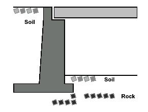
42 Corrugated Metal Culvert B TOP OF CORNER PLATE A SPRINGLINE F E HORIZONTAL SPAN OF TOP ARC C CORNER PLATE BOTTOM PLATE D
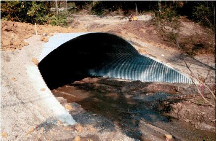
43 CMC Image
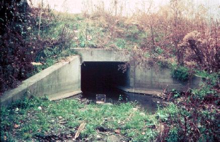
44 RCBC
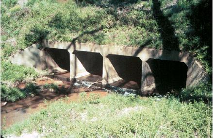
45 Multi-Barrel

46 Multi-Barrel Traffic Slab

47 Circular Metal Culvert

48 Timber Culvert

49 CMC Image

50 Twin-Barrel Multi-Purpose

51 RCBC Apron

52 RCBC Energy Dissipator

53 CMC Interior View

54 CMC Wingwall

55 Timber Culvert

56 Arch Bridge/Culvert?
57 Bridge Nomenclature
58 General Bridge Nomenclature
59 Pier Nomenclature
60 Hammerhead
61 Pier Nomenclature

62 Tied Column
63 Pier Nomenclature

64 Pile Bent

65 Solid Pier
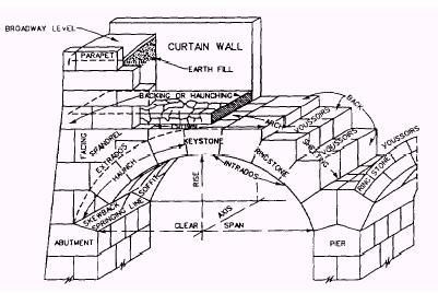
66 Arch Bridge Nomenclature

67 Arch Masonry
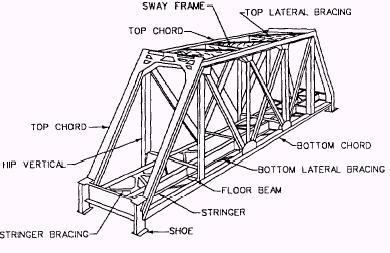
68 Truss Nomenclature
69 Bearing Nomenclature
70 Cracks Nomenclature
71 Abutment Components BACKWALL BRIDGE SEAT BACKWALL CAP BEAM FLOATING WINGWALL C O L U M N C O L U M N CAP BEAM C O L U M N FOOTING FOOTING FOOTING
72 Abutment Components
73 Classification of Bridges by Materials Timber Concrete Steel Masonry

74 Bailey Bridge w/o Running Board

75 Glue Laminated Bridge
")
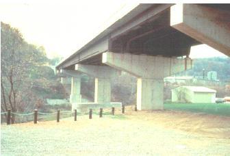
76 Concrete (RCDG) Bridge

77 Concrete Arch Bridge

78 Steel Girder Bridge

79 Steel Truss Girder Bridge

80 Steel Arch Bridge

81 Steel Truss Through Bridge

82 Suspension Bridge

83 Special Steel Bridge
84 Classification of Bridges by Structural Systems Slab/T-Beam Deck Girder Through Bridge Multi-Span Continuous Splan Arch Bridge Rigid Frame Tied Arch Bridge Suspension Cable Stayed
85 Slab/T-Beam Bridge

86 Concrete Slab Bridge

87 Concrete T-Beam Bridge
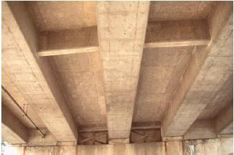
88 Deck Girder Bridge

89 I-Girder Bridge

90 Box Girders
91 Through Bridge

92 Steel Truss Through Bridge

93 Timber Through Bridge

94 Multi-Span Simple Bridge

95 Multi-Span w/column Bents
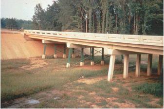
96 Multi-Span Concrete
97 Multi-Span
98 End of Presentation