MASTER PLANNING THE ENTIRE BUILDING AN INTEGRATED ARCHITECTURAL AND ENGINEERING APPROACH. Why is Engineering Important to Master Planning Design?
|
|
|
- Beverley Hill
- 5 years ago
- Views:
Transcription

1 MASTER PLANNING THE ENTIRE BUILDING AN INTEGRATED ARCHITECTURAL AND ENGINEERING APPROACH Why is Engineering Important to Master Planning Design?

2 MASTER PLANNING THE ENTIRE BUILDING AN INTEGRATED ARCHITECTURAL AND ENGINEERING APPROACH Your Presenters Dennis Vonasek, AIA Architect Healthcare Principal HGA Architects and Engineers Jeff Harris, PE Mechanical Engineer HGA Architects and Engineers Krista McDonald Biason, PE Electrical Engineer HGA Architects and Engineers
3 MASTER PLANNING THE ENTIRE BUILDING AN INTEGRATED ARCHITECTURAL AND ENGINEERING APPROACH Agenda Learning Objectives Team Roles Master Planning Definition Process Tools Financial Impact Case Studies Questions, Comments and Queries
4 Learning Objectives
5 LEARNING OBJECTIVES Understand objectives of master planning Determine options for Engineering systems to complement architectural programming needs Evaluate facility needs for new, modified or upgraded engineering systems and planning Identify opportunities to incorporate engineering master planning efforts
6 Team Roles

7 TEAM ROLES Roles Misconception Owner Has money to spend Architect Designs a showpiece building Engineer Designs complicated systems that aren t understood by anyone else.
8 Roles Redefined Engineer Architect Owner Master Plan
9 Master Planning Definition
10 MASTER PLANNING DEFINITION Facility Master Plan CRITERIA Improve Patient and Staff Safety Reduce or Optimize Operational Costs Create Ideal Patient Experience Long Term Flexibility Careful Stewardship of Resources Support Physician and Staff Recruitment and retention Maximize Return on Investment Create a sustainable solution Incorporate resiliency
11 Facility Master Plan SPECIFIC PROJECT PRIORITIES EXAMPLE MASTERPLAN PROJECT GOALS Continue hospital inpatient services as a key strategic distinction in the community, but right size capacity to match the community need. Address safety, accreditation, maintenance, and structural issues in current facilities Deliver exceptional services deployed in easy to access, impressively branded facilities. Assure safe, effective and efficient performance by developing an efficient, universal inpatient care platform.

12 So, when do Engineers enter the picture? And how can their efforts complement the architectural programming needs?

13 AN ARCHITECT S VIEWPOINT I do not like ducts. I do not like pipes. I hate them really thoroughly. But because I hate them thoroughly I feel that they have to be given their place. If I hated them and took no care, I think they would invade the building and completely destroy it. I want to correct any notion you may have that I am in love with that kind of thing. Louis Kahn, World Architecture 1964 Centre Georges Pompidou Not a Louis Kahn Building

14 A Century of Engineering Design
15 Master Planning Process
16 MASTER PLANNING PROCESS Process Overview Step ONE Step TWO Step THREE Step FOUR Step FIVE Step SIX Send questionnaires to departments Current state meetings Future state meetings Extreme schemes of master planning Owner master plan final review Board report out

17 Process Engineering When to include Engineering When not to Include engineering

18 Master Planning Preliminary Questions Project Vision Is program already planned Is expansion realistic Is it necessary Type of Construction Remodel / Expansion Greenfield Site Existing Campus Who owns the building Location of building Urban Rural Strip mall
19 Operational and Planning Considerations Business Success Increase Market Share Increase Patient Volume Flexibility Ongoing Operations Meet Schedule and Budget Patient Experience Wayfinding Convenience Healing Environment HCAPS Staff Retention Recruitment Productive and Efficient Functionality Maintenance & Operations Infrastructure Adaptability Resiliency Need for new, modified, or upgraded engineered systems
20 Master Planning Tools
 A3s Basis of Design (BOD) Forced Ranking Set Logs Component Design Match tools to Project and")
21 MASTER PLANNING TOOLS Many Tools Available Program Pull scheduling Owner s Project Requirements (OPR) A3s Basis of Design (BOD) Forced Ranking Set Logs Component Design Match tools to Project and Team
22 Clinic Program Summary January 21, Program ARCHITECTURAL SPACES Here is where we start Space program Modalities Expansion plans Architectural design flexibility Infrastructure Space Needs Total DGSF Actual DGSF Public / Lobby A. Public and Patient Support - Entry 2,171 1,743 B. Central Registration/ Appointment Center Provid er/ Clinic Space C. Clinic Module 30,083 30,818 C1. Urgent Care Module 3,423 4,109 D. Clincal Support 8,628 7,558 E. Staff Support 1,946 2,226 Ancilla ry Space F. Pharmacy 2,445 2,116 G. Diagnostic Imaging 4,437 4,278 H. Therapy - PT/ OT/ Speech 7,765 6,976 J. Clinical Laboratory 2,113 2,125 Health and Wellne ss K. Conference/ Education Center 2,500 1,313 L. Retail 1,670 1,351 Admini stratio n M. Administrative Offices 1,885 2,242 Suppor t N. Building Support Area 1,463 1,161 COMMENTS Total DGSF 71,438 68,652 DGSF to BGSF Multiplier Total BGSF 85,725 87, Line item add for enclosed mechanical pent

23 Program Infrastructure Base Line Mechanical Rooms and Penthouses 7 to 9% of Building Gross Square Feet (BGSF) 16 feet clear vertical height Access to exterior walls Shafts 0.27% of BGSF- 1 sf per 375 sf One shaft per smoke compartment- Aligned vertically Coordinated with structural system

24 Program Infrastructure Base Line Main Electrical Rooms 1 to 2% of BGSF Distribution Closets 8x10 is good for planning- stacked Server Room 1 sf per 100 of total GSF Tele/Data Rooms Minimum 10 x15 or Owner s standards Central Plant 2 to 3% of BGSF


25 Program Code Considerations These are only some of the documents required for health care design


26 Existing System Evaluation ELECTRICAL CONSIDERATIONS Age of system Condition of equipment Code compliance Applicability Desire for future flexibility

27 High Level Pull Schedule CONSIDERATIONS Program Needs Staffing and Department Considerations Infrastructure to support program Utility location Phasing Department of Health Approvals AHJ Approvals
28 Tools Owner s Project Requirements Design Goals Future Provisions System Descriptions TOOLS Functional Goals Equipment Details System Details


29 Tools A3

30 Tools Basis of Design

31 Forced Ranking

.")
 is a standalone 100% OA air")
.")

32 Energy Capital Cost Energy Cost Healthcare Environmental Quality Sustainability Complexity Flexibility Redundancy Space Needed Maintenance MAIN GOALS Evaluation Criteria ID Description Alt 2 Water Cooled Magnetic Bearing Chiller w/cooling Tower This option could also use a nonmodular heat recovery chiller Tools Set Logs Alt 2 Chilled Beams (Patient areas, admin & wellness/rehab areas). 100% OA AHU The air handling unit serving the chilled beam system(s) is a standalone 100% OA air handling unit. In the energy model this is dealt with separately. Alt 2 Overhead Variable Air Volume (remainder of buidling). 25% Min OA AHU The air handling unit serving the variable air volume system(s) is a standalone 25% min. OA air handling unit. Alt 2 Radiant Floor Heating (Perimeter of new building, match existing building) Radiant floor heating is used through out the existing building and will be continued through out the new building. Alt 2 Gas Fired Condensing Boilers Alt 2 Supplement w/exisitng Facility

33 TOOLS COMPONENT DESIGN
34 Master Planning Financial Impact

35 Financial Impact Example New Project COMPONENT TEAM PRICING PROJECT COST $10.3 M Approximately $6.8 M Construction Cost Approximately $3.5 M Soft Costs
36 Cost Impact What can the project afford? Rarely shifts towards infrastructure budget What is the code required minimum? Where is the money best spent? Stakeholder input: Who will yell the loudest if their program doesn t make the final cut?
37 Case Studies
38 Case Study #1 Remodel / Expansion

39 Process Current State REMODEL / EXPANSION

40 Process Future State REMODEL / EXPANSION


41 REMODEL / EXPANSION Process Owner s Project Requirements


42 Process Extreme Schemes REMODEL / EXPANSION

43 Process Report Out REMODEL / EXPANSION
44 Case Study #1 Remodel / Expansion Required Infrastructure upgrades extend beyond program requirements You can t afford it. Misleading budget when based on a square foot basis Multiple phases complicate solution Occupied throughout construction process
45 Case Study #2 Greenfield Site

46 GREENFIELD SITE

47

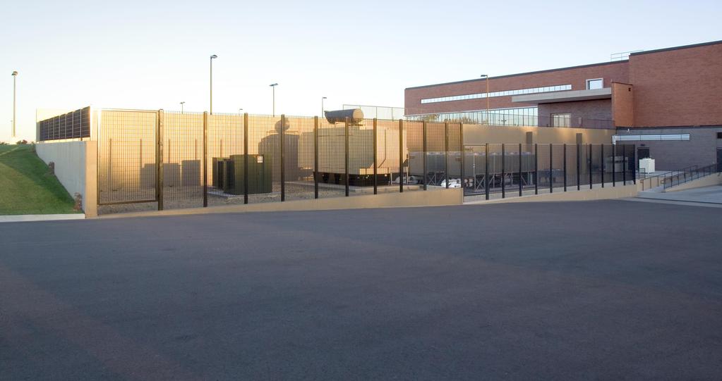
48 Utility Yard GREENFIELD SITE Main Electrical Rooms; Expansion in Room and North Mechanical Room Expansion East Architectural Expansion
49 GREENFIELD SITE
50 Case Study #2 Greenfield First phase of a new campus with imminent expansion Planned growth in multiple directions Infrastructure scaled for future growth

51 Case Study #3 Existing Campus
52 Goals for Masterplan Provide enhanced patient care by Improving patient convenience and satisfaction Increasing operational efficiency of staff Improving recruitment and retention of providers and staff, and increase staff satisfaction Build future capacity by Replacing aging facilities and infrastructure which are at the end of their useful life Building spaces that will enhance the patient experience Developing a strong brand identity

53 53 Current Campus Parkwood Building #1 Hospital Family Medical Center Clinic #1 Cancer Center Rehab Truyu

54 Implementation Future This Masterplan is implemented in four phases Procedure Center Imaging & Emergency Departments Bed Tower Main Clinic 54
 Interventional Suites Cardiology/Minor Procedure SCCU Pre/Post/PACU Beds Extended Stay Beds Patient Access Entry / Public Area Central Sterile Supply Shared")
55 Implementation Phase 1 - Procedure Center Background Grow and renew the procedure platform Move toward private beds EXISTING ED ENTRY EXISTING INPATIENT ENTRY EXISTING REHAB ENTRY Phase 1 Scope Procedure Center / SCCU (125,000 BGSF) Interventional Suites Cardiology/Minor Procedure SCCU Pre/Post/PACU Beds Extended Stay Beds Patient Access Entry / Public Area Central Sterile Supply Shared Staff Support Building Services Electrical Building Loading Dock Associated site work NEW PROCEDURE CENTER ENTRY Make Ready Requirements New west parking lot (550 stalls) w/ retention pond New retention pond Relocate displaced departments in the Hospital. New Electrical Building Demolish generators and portion of Hospital building west of public corridor on lower and main levels 55
 Room for 1 future peak shaving line up New infrastructure sized to accommodate future & relocated mechanical")
56 Infrastructure Masterplan - Phase 1 EXISTING ED ENTRY NEW PROCEDURE CENTER ENTRY EXISTING INPATIENT ENTRY EXISTING REHAB ENTRY Electrical New Electrical Building 2 new generators; 3 relocated generators Room for 2 future generators 3 peak shaving gear (1 new and 2 relocated) Room for 1 future peak shaving line up New infrastructure sized to accommodate future & relocated mechanical equipment and future buildings Existing Central Plant Building Serve existing mechanical equipment in Central Plant with new infrastructure distributed from the new Electrical Building, eliminate utility switches and generator Existing Electrical Vault (LL of Hospital) Feed existing vault with new feeders from new Electrical Building. Existing distribution to be revisited due to event Distribution for Procedure Center(in Procedure Center) Unit substations, transfer switches, distribution panels Fed from switches in new Electrical Building Mechanical Extent of mechanical system in Central Plant remains as is systems rebalanced Add new fuel oil tank for generators In new Procedure Center New steam-to-water heat exchangers with pumps Air-handling units Extend and modify chilled water and steam piping mains

57 Implementation Phase 2 Imaging and Emergency Departments Background The Imaging and Emergency Departments are in the existing Hospital And require crossing the main public corridor to access the Procedure Center. Structural bays and floor-to-floor heights make expanding in place difficult. Phase 2 Scope Imaging / Emergency Departments (57,100 BGSF ) Central Plant Associated site work EXISTING MAIN CLINIC ENTRY NEW PROCEDURE CENTER ENTRY EXISTING INPATIENT ENTRY NEW IMAGING / ED ENTRY EXISTING REHAB ENTRY Make Ready Requirements New Central Plant and cooling towers Relocate displaced departments in the Hospital and Central Plant Demolish existing Central Plant and cooling towers Rework loading dock at Rehab Building 57

58 Infrastructure Masterplan - Phase 2 EXISTING MAIN CLINIC ENTRY NEW PROCEDURE CENTER ENTRY EXISTING INPATIENT ENTRY NEW IMAGING / ED ENTRY EXISTING REHAB ENTRY Electrical Add additional distribution equipment for new and relocated mechanical loads in new Central Plant Add and modify distribution equipment in Imaging/ED Mechanical New Central Plant Migrate existing 2 chillers and associated pumps New cooling tower pumps New chilled water distribution pumps Add new steam boilers as back-up for UND steam supply Relocate and upgrade building automation management control center Adjacent to new Central Plant Add new cooling towers and associated pumps Demo fuel tanks and add new fuel tanks Relocate O2 Existing Plant Demo building and equipment that is not to be relocated Maintain small distribution hub in location of existing plant for incoming steam Rework existing steam piping to accommodate new building layout In Image/ED Building New steam-to-water heat exchangers with pumps Air-handling units Extend and modify chilled water and steam piping mains 58
 Program relocation Demolition Associated site work NEW INPATIENT AND OUTPATIENT ENTRY NEW ED DROP-OFF Make Ready Requirements None EXISTING REHAB")
59 Implementation Phase 3 Bed Tower Background With a new diagnostic and treatment platform complete and an aging existing Bed Tower, a new Bed Tower is able to begin construction. Phase 3 Scope Bed Tower 220 beds (180,840 BGSF ) Program relocation Demolition Associated site work NEW INPATIENT AND OUTPATIENT ENTRY NEW ED DROP-OFF Make Ready Requirements None EXISTING REHAB ENTRY NEW PROCEDURE CENTER ENTRY 59

60 Infrastructure Masterplan Phase 3 Electrical Add additional distribution equipment for new and relocated mechanical loads in new Central Plant Add and modify electrical equipment for new tower NEW INPATIENT AND OUTPATIENT ENTRY NEW ED DROP-OFF EXISTING REHAB ENTRY Mechanical Central Plant Add 4 th chiller and associated pump Adjacent to Central Plant Add 1 new cooling tower with associated pumps in the Central Plant In new Bed Tower New steam-to-water heat exchangers with pumps Air-handling units Extend and modify chilled water and steam piping mains NEW PROCEDURE CENTER ENTRY 60

61 Implementation Phase 4 Main Clinic Background The Main Clinic is undersized by current design standards with no capacity for adding new physicians Phase 4 Scope Main Clinic (140,500 BGSF) Demolition Fleet vehicle building Associated site work NEW INPATIENT AND OUTPATIENT MAIN ENTRIES NEW ED DROP-OFF Make Ready Requirements Utility Modifications NEW PROCEDURE CENTER ENTRY 61

62 Infrastructure Masterplan Phase 4 Electrical Provide exterior normal and emergency feeders from Electrical Building to new Clinic NEW INPATIENT AND OUTPATIENT MAIN ENTRIES Mechanical In new Clinic Building New steam-to-water heat exchangers with pumps Air-handling units Extend and modify chilled water and steam piping mains NEW ED DROP-OFF EXISTING REHAB ENTRY NEW PROCEDURE CENTER ENTRY 62

63 Future Growth
64 Case Study #3 Existing Campus Phased replacement of 1970 s campus Through 4 large phases and multiple make ready projects Address sustainability and resiliency Address electrical and mechanical code deficiencies Provide measures to address natural disasters Maintain occupancy for all phases until project completion in 2024


65 THANK YOU! Questions, Comments and Queries