The Construction of the Langham Place in Mong Kok An Introduction
|
|
|
- Bathsheba Parrish
- 5 years ago
- Views:
Transcription
1 The Construction of the Langham Place in Mong Kok An Introduction

2 Artist Impression of Langham Place
3 r o j e c t c o m p r i s i n g a i l / h o t e l c o m p a n o f f i c e / r e t Fast Fact The site located in the heart of the Mongkok District and bounded on four sides by Argyle Street, Portland Street, Shan Tung Street and Shanghai Street, with a site area of about 12,000 square metre.
4 In the project, a retail/shopping/entertainment centre of 51,000 sq. m; a Grade A office tower of 70,000 sq. m, and a 5-star Langham Place Hotel of 40,000 sq. m. comprising about 720 rooms are constructed. In addition, 6,000 sq. m. of building area are used as Government/ Institution/Community facilities including a public light bus terminus in the ground level of the hotel block.
5 Total Contract sum about $3.5 billion. Contractor: Sun Fook Kong Holdings Limited Foundation Contract commenced in March 1999 to November 2001 Main Contract commenced in December 2001 for completion in July 2004

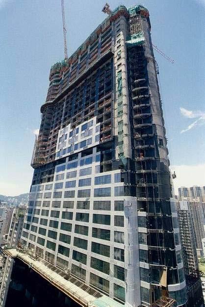
6 External view of Langham Place at seen in November 2003
7 Foundation Works in general

8 Layout Plan showing the cut-off arrangement and location of bored piles

9 The site as seen in 1999 before the commencement of foundation works

10 The site as seen in June 2000 at the early stage of foundation construction


11 Foundation Work at Site A Foundation Work at Site B


12 Forming the large diameter bored pile using RCD (left) and Grab & Chisel Method


13 Excavation for the diaphragm wall Other cut-off provision using bored pile
14 Construction of the Office Tower Basement portion

15 Commencement of excavation to form the raft foundation for tower block


16 Provision of a work platform for the stationing of equipment and handling of spoil to facilitate the excavation process


17 Detail of the lateral support frame as seen inside the excavation pit


18 Construction of the basement structure using in-situ timber formwork from the foundation raft Composite column for the tower block


19 Gradual ascending of the basement structure


20 Detail of the composite column


21 Dewatering arrangement well points provided around the cut-off wall

22

23

24


25 Completion of the basement portion of the tower block up to ground level
26 Construction of the Office Tower Podium/Transfer plate


27 Construction of entrance foyer and the transfer plate for the support of the tower block upper structure 3m thick Transfer plate on top of the super-column for redistributing of the column loading of the upper structure

28 Slab and core wall below the transfer plate
29 Construction of the Office Tower Core Wall


30 Erection of a climb-form for the construction of the core wall starting from the transfer plate Completed climb-form ready for operation


31 Erection of the climb-form Panels before erected onto the main frame of the formwork system

32 Climb-form erected on the transfer plate ready for the first lift The first section of core wall was formed by the climb-form without lifting

33


34 The climb-form system as seen on the platform deck level Hydraulic jack for lifting the form system


35 The climb-form system as seen under the platform deck


36 Detail of the hydraulic jack that lifts the climb-form


37 Climb-form being dismantled after the topping out of the core wall at 58/F The external view of the climb form under routine operation
38 Construction of the Office Tower Floor System

39 Construction of the typical floor of the office block using a table form


40 Detail of the table form

41 Forming of the floor in two phases


42 Traditional timber floor was used at a later stage A special climbing-type material hoist for lifting of formwork material from lower floor to the deck level


43 Floor beams take shape


44 Link bars provisioned in core wall for connecting the floor slab and beam afterward The jointing of the slab to the core wall
45 Construction of the Office Tower Outrigger System

46 Two sets of outrigger frames were provided on 26/F and 44/F to stiffen the superstructure


47 Detail of the outrigger and the outer truss

48


49 Connection of the outrigger member to the floor and core wall


50 Encasing the outrigger frame with concrete at a later stage
51 Construction of the Retail Podium Basement

52 Forming the ground floor slab as the first plate before the full-scale commencement of the basement works


53 Forming of the ground floor slab by the support of the steel columns Steel columns founded on bored-pile as support for the basement structure during the top-down construction process


54 Onward development of the ground floor slab

55 Muck-openning Completion of the ground floor slab with a muck-opening temporary provided to facilitate further excavation downward


56 Onward excavation worked around the muck-opening


57 Onward excavation inside the basement

58

59 Vehicular ramp Forming the vehicular ramp at Shan Tung Street which served also as the temporary access for the removal of spoil from the basement


60 Constructing the ramp in top-down manner using traditional timber formwork

61 The vehicular ramp undergoing a top-down construction process at seen at the lower basement level
62 Construction of the Office Tower Other Features


63


64


65


66 Finishing the office interior


67 Building services installation


68 An semi-self climbing scaffold provided as work screen on the top deck levels


69 Temporary material hoist


70 Roof features provision of a steel dome at the roof of the tower block
71 Construction of the Retail Podium Podium Structure


72 Commencement of the retail podium construction with floor slab supported on steel columns (the first 2 levels of podium constructed in RC slab)

73 Void for an interior atrium strip Forming the steel frame of the retail podium

74 The void for the atrium Forming the steel frame of the retail podium

75 Voids as atrium spaces


76 Development of the podium structure

77 The framing arrangement of the podium as seen on the intermediate levels


78 Detail seeing the complicated layout of the structural steel frame


79 25m high atrium Complicated interior space within the podium
80 Construction of the Retail Podium Roof and the Atrium

81 a The 30m-high Grand Atrium located on the 4-level of the retail podium


82 Installing the trussed columns for the Grand Atrium


83 Temporary trusses Temporary lateral trusses erected in rows to stabilize the steel columns before the final erection of the roof trusses

84 The 30m high Grand Atrium space took shape


85 Grand Atrium space formed by trussed columns and a trussed roof frame


86 a Sequential views to see the gradual completion of the podium (1)

87 Sequential views to see the gradual completion of the podium (2)

88 Sequential views to see the gradual completion of the podium (3)

89 Sequential views to see the gradual completion of the podium (4)


90 Laying the roof deck and the roofing layer


91 Spaces inside the podium roof and atrium interior


92 Spaces inside the Grand Atrium interior
93 Construction of the Hotel Block

94 An aerial view seeing the hotel block and the retail podium


95 Roof Features Lift core Hotel room block
96 Construction of the Hotel Block Basement


97 Commencement of the basement excavation by installing the first layer of lateral support strut frame


98 Seeing the excavation inside the basement pit


99


100 Works at the formation level


101 Construction the basement from the formation level using bottom-up approach


102 Forming the basement wall
103 Construction of the Hotel Block the Superstructure


104 Composite columns are used up to 3/F to provide larger span at the ground level which used as a public transport facility Construction of the podium of the hotel block


105 Lift core block Hotel compartment block


106 Construction of the lift core block using a type of large-panel formwork


107 Layout of the large-panel steel formwork for the construction of the load bearing walls of the hotel apartment block


108 Formwork detail as seen on deck level


109 Roof features

110 Installation of the curtain wall
111 Other Provision Pedestrian Tunnel crossing Shanghai Street


112 Forming of a cut-off across Shanghai Street using drilled piles

113 Temporary traffic diversion arrangement during the forming of the cut-off for the underground vehicular tunnel

114 Temporary traffic diversion arrangement during the forming of the cut-off for the underground vehicular tunnel


115 Excavate and constructing the tunnel in phases using bottom up method.
116 Other Provision Pedestrian Footbridge crossing Shanghai Street


117 Construction of two footbridges to link up the two buildings within the development

118 Completion of the steel footbridges ready for the installation of glass wall
119 End of presentation