GUIDELINES FOR EARTHQUAKE RESISTANT DESIGN
|
|
|
- Eunice Wright
- 5 years ago
- Views:
Transcription

1 GUIDELINES FOR EARTHQUAKE RESISTANT DESIGN Dr. G. P. Chandradhara Professor of Civil Engineering S. J. College of Engineering Mysore E mail : chandu_gpc@yahoo.com Mobile:
2 General Guidelines for Planning Building and its Structure Should Have a Uniform and Continuous Distribution of Mass, Stiffness, Strength and Ductility 2
3 Building Configuration: Problems & Solution Problem in Extreme Direction Structural Problem Remedial Measures Extreme height/depth ratio High overturning forces, Large drift causing non-structural damage, foundation stability Revise proportion or special structural system Extreme plan area Built-up large diaphragms forces Subdivide building by seismic joints Extreme length depth ratio Built up of large lateral forces in perimeter, large differences in resistance of two axes Experience greater variations in ground movement and soil conditions Subdivide building by seismic joints 3
4 Building Configuration: Problems & Solution Problem of Vertical Layout Vertical set back & reverse setbacks Soft frame storey Variation in column stiffness Structural Problem Stress concentration at notch, different periods for different parts of building, high diaphragms forces to transfer at setback Causes abrupt changes of stiffness at point of discontinuity Causes abrupt changes of stiffness, much higher forces in stiffer columns Remedial Measures Special structural systems, careful dynamic analysis Add bracing, Add columns, braced Redesign structural system to balance stiffnesses 4
5 Design of Soft storey frame Special arrangements are necessary to increase the strength and stiffness 1. Dynamic analysis is carried out by considering stiffness and mass distribution and inelastic deformation of the members OR 1. Columns and Beams of soft storey are to be designed for 2.5 times storey shear and moments calculated under seismic loads. 2. Shear walls are provided in both the parallel direction away from the cente of the building and need to be designed for 1.5 times the lateral storey shear.
6 Guidelines for Planning Arrangement of Columns Good arrangement of columns Poor arrangement of columns 6
7 Guidelines for Planning Y Rotation about the axis x x Building is strong about YY axis and weak About XX axis Y x Y x Provide columns to make it strong about XX axis 7
8 Redundancy in Building Simple Connection One load path Rigid Connection Two load paths Walls Column/Beam 8
9 POUNDING Maintain a good distance Between adjacent tall Buildings to avoid Collision during oscillation 9

10 Whip Effect of Apartment Bhuj
11 Building Configuration: Problems & Solution Problems of Adjacency Building separation (Pounding) Structural Problem Possibility of pounding dependent on building period, height, drift, distance Remedial Measures Ensure adequate separation, assuming opposite building vibrations 11


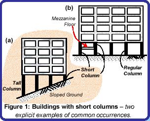
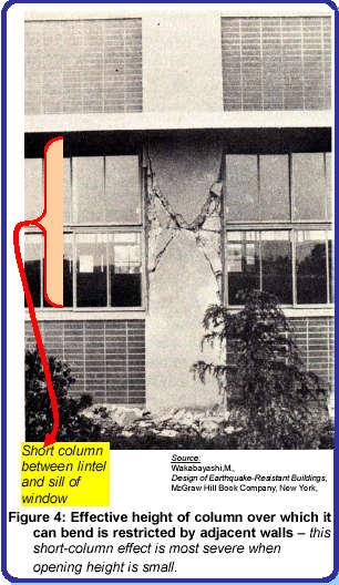
12 Short Column Behavior Short Column Behavior 12

13 Shear Failure in Captive Column Brittle shear failure of columns and beams Buckling of longitudinal bars in beam - columns due to inadequate spacing or lack of transverse stirrups Shear failure of columns which were shortened by the supporting effect of non structural elements Brittle failure in corner columns caused by torsion and biaxial bending effects 13


14 The diagonal cracks and shear failures in the short columns of a multi-storey car park almost caused collapse (Northridge, California 1994) 14
15 15
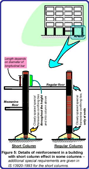
16 CAPTIVE COLUMNS opening Beam opening Captive column opening c o l masonry u m n Solution: masonry 1. Add ties at closer spacing. Preferably spiral ties. masonry 2. Provide masonry walls on either side equal to twice the opening sizes by reducing the openings. 3. The best solution is to avoid the opening so that no captive column is created. c o l u m n 16
17 CAPTIVE COLUMNS: SOLUTIONS. Beam L L L L OPENING L 1 2 OPENING 1 a OPENING masonry c o l u m n masonry c o l u m n masonry 17

18 Severe Shearing Effects on Columns 18

19 Short Column behaviour (Kachchh, 2001) 19

20 Short column failure due to insufficient transverse reinforcement or? Krishna Aparments, Airport Road, Bhuj 20

21 Failure of Express highway in Kobe 21

22 Strong Column & Weak Beam Concept The seismic inertia forces generated at its floor levels are transferred through the various beams and columns to the ground. The correct building components need to be made ductile. The failure of a column can affect the stability of the whole building, but the failure of a beam causes localized effect. Therefore, it is better to make beams to be the ductile weak links than columns. 22
23 Strong column and weak beams Good Failure in beams Poor Failure in Columns 23

24 Weak column and strong beams 24

25 PLASTIC HINGE 25

26 Large Span Cantilevers 26
27 27

28 No failure Earthquake Resistant Design Bhuj

29 Weak Link Stair case or Lift well 29


30 Weak Link, Bhuj

31 Weak Link, Bhuj 2001 No lateral load force transfer mechanism to the core Punjal Apartments, Ahmedabad 31

32 Weak Link, Bhuj 2001 Himagiri Aptweak link 32
33 LOSS OF SUPPORT Simple Supports 33

34 Column Beam connection Movement of supports due to horizontal force 34
35 Bad construction practice of casting the ground floor columns up to the bottom of the beam and leaving a gap 35

36 Weak joint, Bhuj

37 Discontinuity of the longitudinal reinforcement Bombay Dying Market, Station Road, Bhuj 37

38 Poor quality materials and workmanship Neelima Park Apartments, Ahmedabad 38
39 L,T, + SHAPE COLUMNS CAN BE USED TO INCREASE THE STIFFFNESS OF THE COLUMNS 39


40 Behavior of Symmetrical and Asymmetrical Buildings
41 Location of Centre of Mass
42 Location of Centre of Mass The center of mass wrt A (9.76, 4.10) A A
43 Location of Centre of Stiffness Plan of one Storey Building with size of columns being same Stiffness of all the columns are same
44 Location of Centre of Stiffness (COS) Y In Y direction the Three frames are symmetrical, COS lies along symmetrical X axis In X direction there are 4 frames. Let the lateral Stiffness of each frame be k X A X The center of mass w.r.t.a (8.75, 5.0)

45 45