Pavement Rehabilitation Options in Indiana. Dave Holtz Tommy E. Nantung Lisa Egler-Kellems Indiana Department of Transportation
|
|
|
- Arnold Blankenship
- 5 years ago
- Views:
Transcription
1 Pavement Rehabilitation Options in Indiana Dave Holtz Tommy E. Nantung Lisa Egler-Kellems Indiana Department of Transportation
2 Decision to select treatment options Rehabilitation Treatment Overview
3 Objectives Identify maintenance/rehabilitation treatments. Benefits of good timing. Preventive maintenance and its principles.
4 Introduction How do PCC pavements typically deteriorate? When is functional performance impaired? What about structural performance? What treatments are commonly used?
5 PCC Rehabilitation Treatments PCC Overlays HMA Overlays PCC Pavement Recycling Accelerated Rigid Paving Techniques Feasible Treatment Identification
6 Treatment Information Definitions Purpose and Applications Limitations and Effectiveness Design Considerations Pavement Surveys Cost Considerations Construction Considerations Equipment
7 Identification of Candidate Treatments Specific Distresses Present Condition Functional Structural Loadings and Environment Available Tools Decision trees Decision matrices
8 Treatment Timing Issues What factors affect treatment timing? When is too soon? Too late?
9 Typical Pavement Performance Curve Good Pavement Condition (Functional or Structural) Poor Time (Years)
10 Typical Pavement Performance Curve Good Pavement Condition i Routine Poor Maint. Defer Action Preventive Maintenance Reconstruction Resurfacing Time (Years)
11 Cost Effects Good Pavement Condition i $1 here... or $4-10 here? Poor Time (Years)
12 Preventive Maintenance Planned strategy Preserves the system Retards future deterioration Maintains or improves functional condition
13 Anticipated PM Benefits Good Functional Pavement Condition (e.g. Ride Quality) Poor Time (Years)
14 Anticipated PM Benefits Functional Performance? Structural Performance? Costs: To the agency? To the user?
15 Conventional Rehabilitation Treatment HMA Pavement Overlay
16 Introduction Most popular method Relatively fast and cost-effective means for: Correcting deficiencies Restoring user satisfaction Adding structural t capacity Poor performance is NOT uncommon
17 Definitions Functional performance - Ability to provide a safe, smooth riding surface Structural performance - Ability to carry traffic without distress Empirical - Design based on past experience or observation Mechanistic - Design based upon engineering mechanics
18 Purpose and Applications Improve functional and/or structural characteristics Wide range of applications Road surface categories Climate and support conditions
19 Characteristics of Typical HMA Overlay Dense graded HMA Flexible or rigid surface 25 to 200 mm (1 to 8 in) thickness Mill and Fill
20 Limitations and Effectiveness Why do we have premature failures? Improper p selection Wrong type Inadequate design Insufficient preoverlay repair Lack of consideration of reflection cracking
21 Limitations and Effectiveness What limits the effectiveness of HMA overlays? Distress exhibited in HMA Intended design life of the overlay Availability of quality materials
22 Limitations and Effectiveness How can we improve our overlays? Preoverlay treatments Better materials and practices Sound engineering judgment
23 Overlay Selection to Correct Deficiencies Thin Overlay Thick Overlay Surface Defects Structural Defects
24 What Are Considerations in Overlay Selection? Construction feasibility Traffic control Constructibility Vertical clearances Utilities Performance period Funding
25 Preoverlay Treatment and Repair Dependent upon: Type of overlay Structural adequacy of existing pavement Existing types of distress Future traffic Physical constraints Cost


26 To Repair or Not to Repair?
27 Types of Preoverlay Treatments Localized repair (patching) Surface leveling Controlling reflection cracking Drainage improvements
28 Conventional Rehabilitation Treatment Concrete Pavement Overlay
29 Types of Whitetopping Overlays Conventional Whitetopping Slabs greater than 100 mm thick Placed directly on HMA pavement (little preoverlay repair) Ultra-Thin Whitetopping Thin slabs (50 to 100 mm thick) Short joint spacing (0.6 to 1.8 m) Bonded to existing HMA to increase load- Bonded to existing HMA to increase load carrying capacity
30 Conventional Whitetopping Interface PCC Overlay Existing HMA Pavement Subbase
31 Applicability Conventional Whitetopping Badly deteriorated HMA pavements Most any traffic volume Ultra-Thin Whitetopping Low volume roads exhibiting rutting, shoving, potholing Urban intersections where recurrent rutting/washboarding g has been a problem
32 Overlay Selection Detailed pavement evaluation (distress, FWD, coring) Construction feasibility Performance period Cost effectiveness
33 Whitetopping Feasibility Constructibility Vertical Clearance Traffic Control Construction Conventional Can be a problem May be difficult to construct under traffic No special equipment
34 Whitetopping Feasibility Performance Period Conventional Existing Very deteriorated Condition HMA pavements Extent of Repair Future Traffic Limited to very severe areas Any traffic level Historical i Reliability Very good
35 Design Considerations Slab thickness Joint design Drainage design Reinforcement design PCC mix design Preoverlay repair and surface preparation
36 Preoverlay Repairs Whitetopping Overlays Localized repair of failed areas Filling of potholes Milling if rutting greater than 50 mm Repair of severe alligator cracking if poor support would otherwise result Goal: Uniform support
37 Construction Whitetopping Overlays Conventional PCC paving equipment and construction practices are used PCC may be placed directly on HMA or on milled or leveled HMA surface Whitewashing of HMA surface may be required on hot days
38 Whitetopping Joint Sawing Consider increased saw depth over major distortions D +50mm PCC Overlay HMA Pavement Sawcut Depth D/3


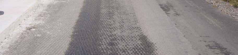
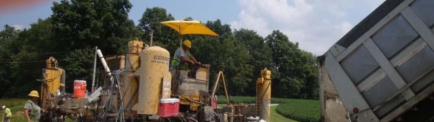

39 SR-161 Whitetopping


40 SR-161 Whitetopping
41 Rehabilitation Option Hot In-Place Recycling

 RAP mixed with additives and relaid Immediate")
42 Hot In-Place Recycling Description Three methods Surface recycling Remixing Repaving Typical depth: 15 mm - 50 mm (0.6 in in) RAP mixed with additives and relaid Immediate opening to traffic Applicable for all traffic levels 5-42
43 Rehabilitation Option Cold In-Place Recycling


44 Cold In-Place Recycling Description Cold process Milling depth: 50 mm mm (2 in to 4 in) RAP mixed with additives i and relaid Resurfacing is typically required Most commonly used on secondary and lowvolume roads 5-44
45 Benefits Conserves energy and materials Preserves geometrics Many surface distresses eliminated Improves profile Modifies material characteristics Relatively inexpensive 5-45


46 Basic Asphalt Recycling Manual 5-46
47 In-Place Recycling Measure of Effectiveness Corrects Poor friction Roughness Bleeding Raveling Rutting Poor cross slope Prevents/Delays Cracking Raveling Roughness Slows/Reduces Severity Cracking Moisture damage Negatively Affects None
48 Rehabilitation Option Full Depth Reclamation (FDR)


49 Definition of Full-Depth Reclamation Method of flexible pavement reconstruction that utilizes the existing asphalt, base, and subgrade material to produce a new stabilized base course for a chip seal, asphalt, or concrete wearing surface.
50 Types of Reclamation Methods Mechanical Stabilization Bituminous Stabilization emulsified asphalt expanded (foamed) asphalt Chemical Stabilization Portland cement slag cement lime fly ash Portland cement, slag cement, lime, fly ash, other
51 Challenges Facing Our Roadways Continuing growth Rising expectations from users A heavily used, aging system Environmental compatibility Changes in the workforce Funding limitations Combined with large increases in traffic volumes and/or allowable loads often leads to serious roadway base failures!
52 How do you know if you have a base problem and not just a surface deficiency?


53 Examples of Pavement Distress Alligator cracking Rutting Excessive patching Base failures Potholes Soil stains on surface


54 Advantages of the FDR Process Use of in-place materials Little or no material hauled off and dumped Maintains or improves existing grade Conserves virgin material Saves cost by using in-place investment Saves energy by reducing mining and hauls Very sustainable process
55 Rehabilitation Strategies
56 Sustainable Element of FDR Process 1 mile of 24-foot wide, 2-lane road, with a 6-inch base


57 FDR in Indiana


58 Other Options for FDR
59 Design Issue Pavement Rehabilitation Design
60 Existing pavement section 4 HMA overlay 8.5 JPCP 3 Dense sand Soil subgrade
61 Proposed rehabilitation HMA overlay 8.5 JPCP 3 Dense sand Soil subgrade 12 year LCCA 25 year LCCA Concrete overlay 8.5 JPCP 3 Dense sand Soil subgrade
62 Design alternatives

63 Backcalculation inputs


64 JPCP optimization
65 JPCP optimization result


66 HMA optimization Adding a base layer is more appropriate


67 HMA sensitivity
68 HMA Sensitivity result
69 FDR and New HMA design inputs
70 Decision making process Treatment Selection
71 Treatment Selection Factors Available Funds Staged Construction Traffic Control Lane Closure Minimum Desired Life Future Maintenance Geometric Issues
72 Treatment Selection Factors (continued) Present and Future Utilities Right-of-Way Restrictions Regulatory Restrictions Available Materials and Equipment Contractor Expertise and Manpower Agency Policies
73 Selection Process Develop feasible alternatives ti for evaluation Identify key decision factors important to agency (e.g., cost, service life, traffic control, duration of construction, etc.) Assign weighting values for each decision factor Assign scoring values for each alternative Add scores and rank alternatives
74 Selection Worksheet Decision Factor 1 Decision Factor 2 Decision Factor 3 Decision Factor 4 TOTAL Weight Weight 1 Weight 2 Weight 3 Weight 4 SCORE Alt 1 Alt 2 Alt 3 Alt 4


75