Increasing efficiency through the project lifecycle by applying BIM
|
|
|
- Milo Watson
- 5 years ago
- Views:
Transcription
 Tekla Structures Product Overview Example")
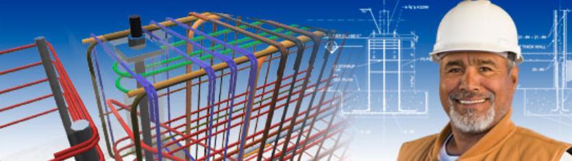
1 Increasing efficiency through the project lifecycle by applying BIM Glen Hutchinson Agenda Company Information Short BIM Intro (Building Information Modeling) Tekla Structures Product Overview Example Projects Case Study 2 1


2 Mission Tekla's mission is to drive the evolution to digital information models, providing a growing competitive advantage for our customers in the construction and infrastructure industries. Sustained growth and profitability for both Tekla and its customers and partners Bringing BIM, i.e. accurately detailed, highly constructible building information models, into the construction industry Bringing a model-based way of working into energy distribution and municipalities' infrastructure management and engineering Being the preferred partner among the leading organizations on the market Attracting with drive and ability and offering a motivating working environment 4 Technology Model-based software products Own technology platform and architecture R&D in Finland, annual investment amounts to nearly 30% of net sales Large amounts of complex information stored in a product model evolution and diverse utilization multi-user access advanced 3D software for the information modeling of buildings and infrastructure Exchange of information with other applications 5 2


 UK Germany")


3 Global network Over 500 employees globally Offices in 15 countries 30 resellers & partners Customers in 100 countries Recently acquired by Trimble USA Sweden Denmark Finland (HQ) UK Germany France Japan Middle East China India Thailand Malaysia Singapore Indonesia Tekla Corporation HQ Tekla office Reseller/partner 6 7 3


4 Technology Adoption Investment Cost ca. 1987, Jukka Suomi drawing plans in a graphics terminal in Tekla s computer room. A graph of Everett Rogers, Technology Adoption Lifecycle Model 8 9 4
5 10 What is BIM? A Building Information Model (BIM) is a digital representation of physical and functional characteristics of a facility. As such it serves as a shared knowledge resource for information about a facility forming a reliable basis for decisions during its life-cycle from inception onward. A basic premise of BIM is collaboration by different stakeholders at different phases of the life cycle of a facility to insert, extract, update or modify information in the BIM to support and reflect the roles of that stakeholder. The BIM is a shared digital representation founded on open standards for interoperability. Approved March 1, 2006 NBIMS Exec Comm. 11 5


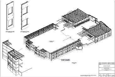
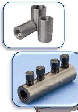
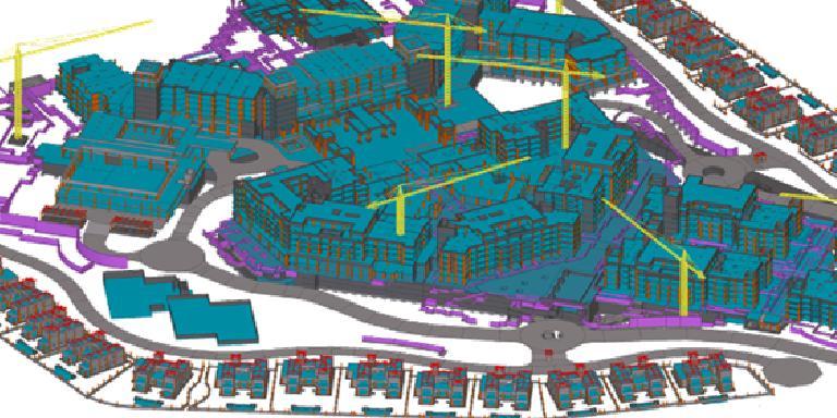
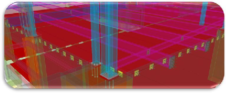
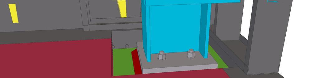
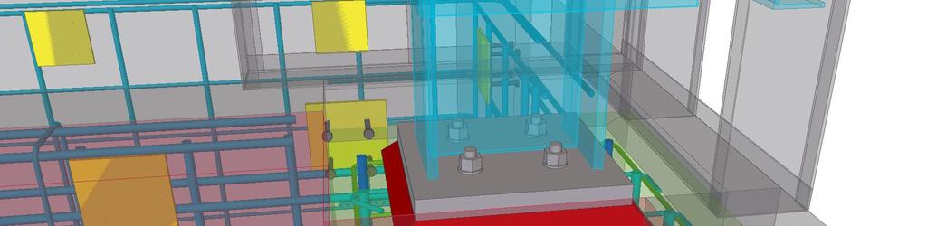
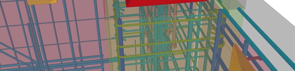
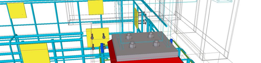
6 12 What s in a Model? DATA Dates Status RFIs Materials BOMs etc All Concrete Construction Components Reinforcement Couplers Reports/Schedules Brick Drawings (Piece Tickets, Sections, Plans, Elevations, 3D Connx.) 13 6


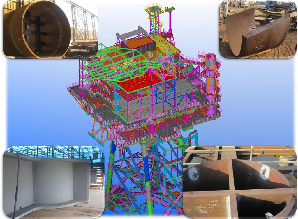
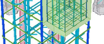
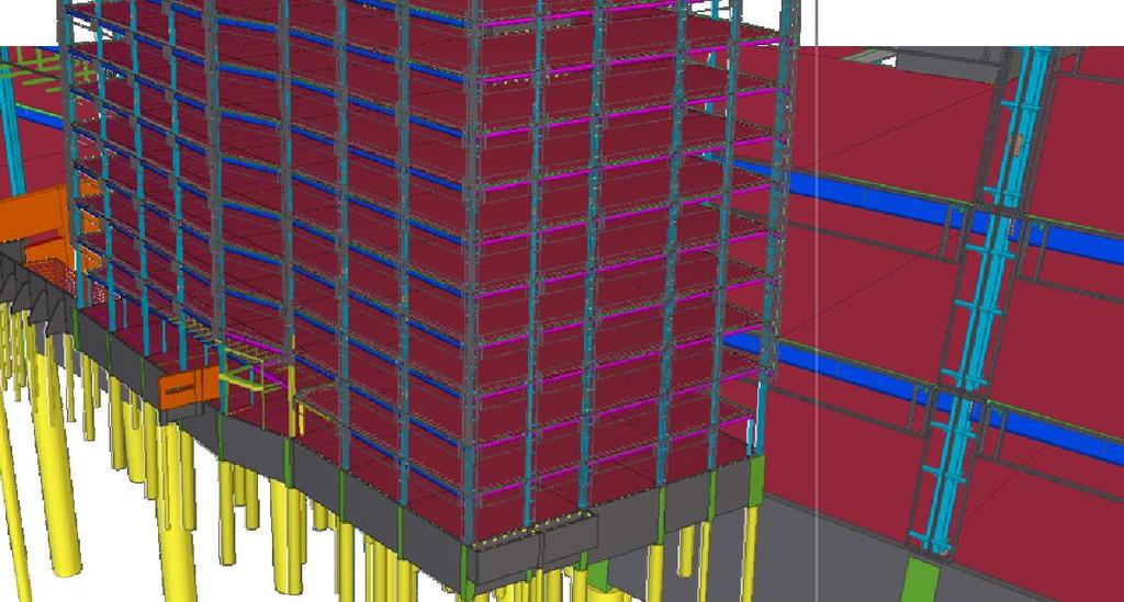
7 Steel Architect Precaster INTERNAL MEP EXTERNAL CIP,Rebar Detailer 14 Tekla Structures Software Full Detailing Steel Detailing Precast Concrete Detailing Reinforced Concrete Detailing Construction Management Engineering Viewer 15 7


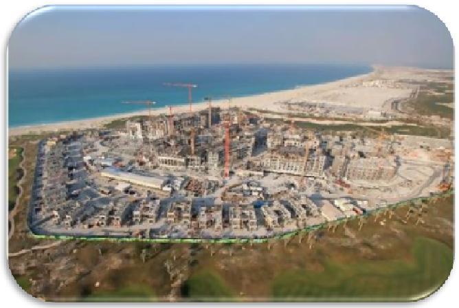
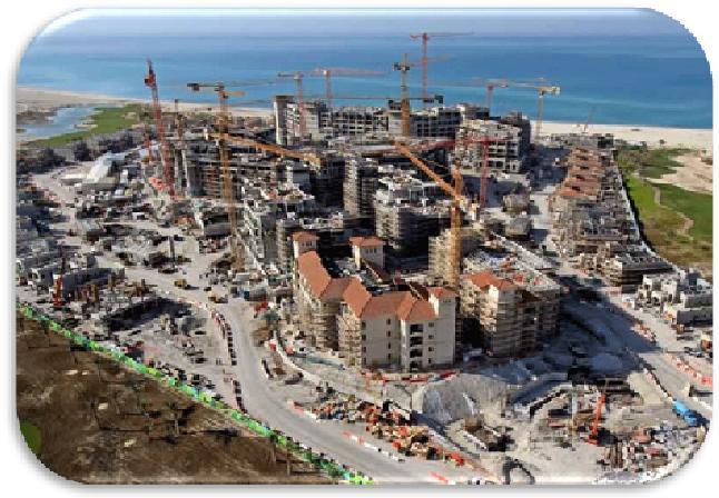
8 Precast Fabricators, detailers, rebar detailers Structural designers Whoare our customers? Cast in Place designers/detailers Steel Fabricators, detailers Contractors, property developers 16 Aldar Properties HQ Abu Dhabi, UAE BIM for Precast Industry 17 8


9 The Gate Tower ADNEC- Abu Dhabi, UAE


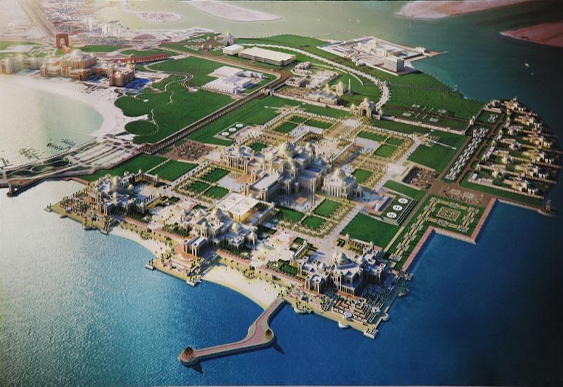

10 Olaya Mall- Al Khobar, Saudi Arabia 20 Presidential Palace, UAE 10


11 KAPSARC (King Abdullah Petroleum Study and Research Center), KSA 22 St. Regis Hotel, Abu Dhabi, UAE 11
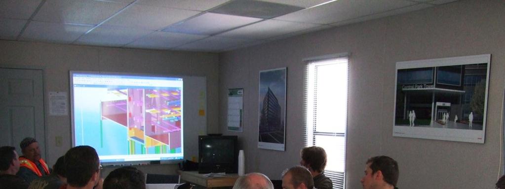
![Case study: Central Park Tower at Interlocken Project Stats 24 [Date]](/docs-images/85/92786446/images/12-2.jpg "[Subject / Author, edit by clicking Insert > Header & Footer] 25 25")
12 Case study: Central Park Tower at Interlocken Project Stats 24 [Date] [Subject / Author, edit by clicking Insert > Header & Footer]


13 Central Park Tower: Project Stats 11 1 Image courtesy Gensler, project architect Location Broomfield, Colorado Height 11 stories 1 level below grade Area 305,331 square feet LEED Gold Certification Below Grade Parking Level: Precast horizontal system to CIP pilasters Quantities 2,849 cy concrete 358 tons reinforcing steel 1,400 tons structural steel 2,470 shop drawings, 47 erection 150,000 sq.ft. exterior wall panels
14 Team Members Developer Architect: MP Engineer: Strut. EOR GC D/B Struc. Cont. IPD Struc. GFRP Panel Fab. Steel Detailer Rebar Fabricator Steel Fabricator: Steel Erector: Prime West Development, Inc. Gensler Swanson Rink Richard Weingardt Consultants The Weitz Company Const. Products Dist., LLC a Weitz Company Structural Consultants Inc. Metro Cast Corp. Axis Steel Detailing Inc. Martino and Luth, Inc. CMC/Banner JD Steel 28 Platforms Used IPD Structural Engineer MEP Engineer General Contractor Design/Build Structural Cont. MEPF Contractor Steel Detailer Rebar Detailer Tekla Structures, ENG AutoCAD MEP Tekla Structures, Vico Tekla Structures, Const. Mgmt. AutoCAD MEP Tekla Structures, STD Tekla Structures, RCD 29 14


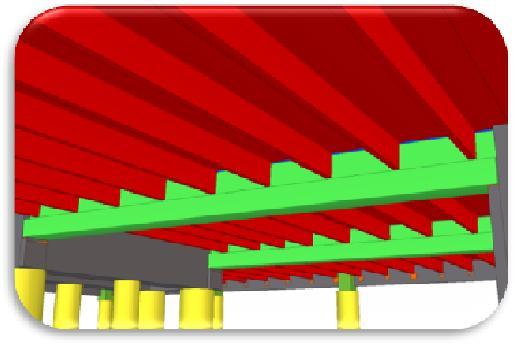
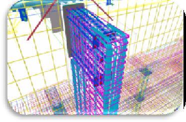
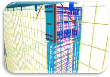
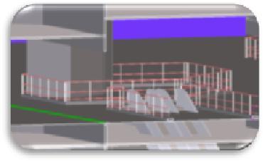
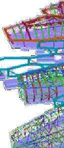
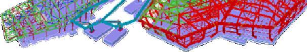
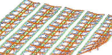
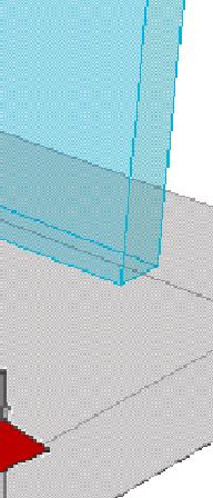
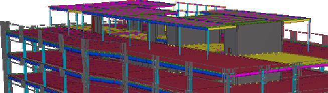
15 What was Modeled 30 Coordination Sharing the Model [Subject / Author, edit by clicking Insert > Header & Footer] 31 15


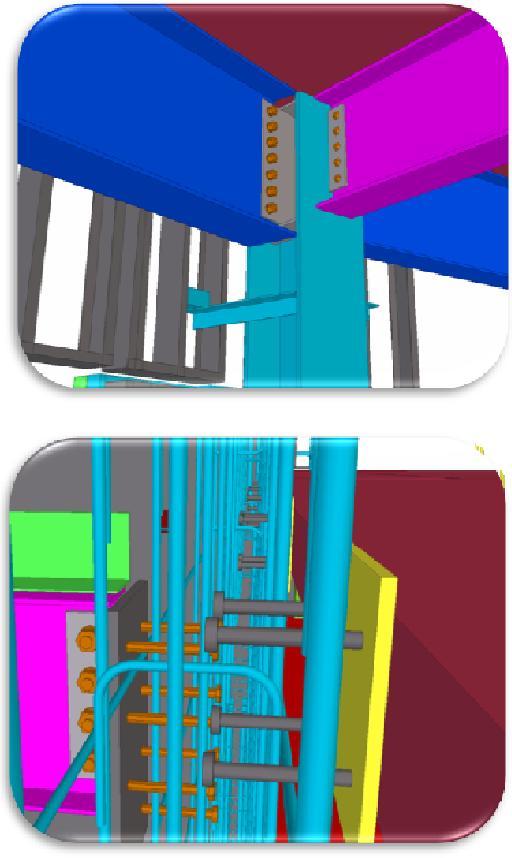
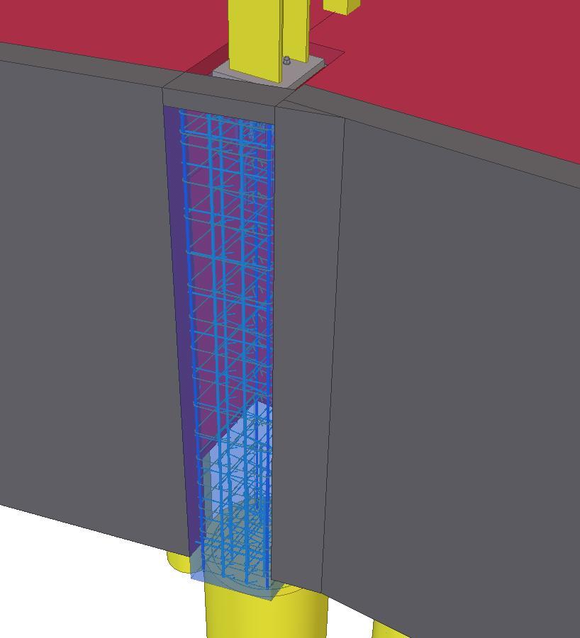
16 Concrete Coordination Concrete Pours, volumes, embeds as per lift Reinforcement Hole vs. Rebar [Date] Virtual Design & Construction Process The Coordination Room Owner/ Design Contractor Owner Engineers Rep


17 What s in the Model? 34 The Process How did they do it 35 17


18 The Delivery Model O A C OAC CM at Risk Integrated Project Delivery Image courtesy Gensler, project architect Developing a Culture of Collaboration 36 Structural Relationship Network General Structural Design Structural / Steel IPD Structural ContractorBuild Subcontractor Detailer / Engineer Fabricator / Steel ReinforcingErector Fabricator Detailer Erector Steel Reinforcing Detailer / Structural Steel Fabricator / Erector Fabricator Detailer Erector Exterior GFRP 37 18


 Designed for constructability Designed for")
19 Getting to Placement of Work: CIP Design Modeled entire structure & exterior GFRP Coordination Designed and modeled all concrete embed plates for attachment of steel and precast Detailing & Constructability 38 Structural and Miscellaneous Steel Design RAM analytical model to start Tekla structural model SCI responsible for design and detailing of structural steel superstructure Participated in design team meetings starting at SD Extracted from model Supplementary contract documents Calculation package (similar to precast package) Designed for constructability Designed for GFRP panel compatibility 39 19


20 VDC and Placement of Work Process - Comprehensive Lift Drawings: For a self-performing general contractor, single most important factor for achieving Quality Productivity Centralized Information - over - many sources of fragmented information 40 Central Park Tower at Interlocken Real Results and Benefits 41 20


21 Project Benefits from the Process Earlier involvement in project commitments made at Schematic Design phase BIM as a process not just as a tool/software Overlapping of design and construction activities Accurate Tekla structural model maintained throughout design/construction phases Extracted supplementary structural drawings from Tekla structural model 42 Cast in Place Concrete Erection/Place Work Comprehensive lift drawings important to quality and productivity CIP performance Major improvement over fragmented sources: Reinforcing Precast embeds Structural steel embeds Miscellaneous steel embeds (elevators, stairs) Blockouts / penetrations 43 21


22 Cast in Place Concrete Benefits Construction Practically no approval comments from the EOR Zero RFI Reduced construction schedule two weeks 21.6% less reinforcing materials actual vs. budget (had three lump sump reinforcing bids) Estimated less than 0.07% waste in reinforcing material Less than 500 # s of reinforcing drop 358 tons of total reinforcing 44 RFI - Benchmark Comparison April Stories Completed on Schedule Village Center Station April Stories Ahead of schedule Central Park Tower 45 22
23 RFI - Comparison of Results from Similar Project Village Center Station Central Park Tower 44 RFIs CIP core walls: These RFIs accounted for 14.77% of total on project Cost range of RFIs $97,549 - $161,549 Zero RFIs in CIP core walls 46 Structural Steel Interactive Design Model / Detail Model Handoffs Prepare Structural CDs INTERACTIVE Structural Steel Shop Drawings by Enhancing Design Model Improve Delivery 40 Days 35 Days Total Review Steel Shop Drawings Review Steel Shop Drawings Fabricate and Deliver First Steel Package 47 23

24 Structural Steel and Misc. Steel Detailing Reduction in detailing hours 1,600 traditional as originally planned 1,050 hours actual Reduction attributed to correcting model at the correct stage 48 Structural Steel and Misc. Steel Fabrication Iterative, concurrent design / detailing processes Expedited fabrication start following CDs reduced by 56% (5 weeks) Reduced initial steel delivery time following CDs by 50% (8 weeks) 49 24


25 Structural Steel and Misc. Steel Erection/Place Work Where preceding work in design, detailing and fabrication bears fruit Only two RFIs (Structural Steel) Zero change orders in erection cost Clash Detection Clash Prevention Management 50 Structural Steel and Misc. Steel Benefits Design Facilitated shop drawing review process few review comments from all of design team Very efficient structural system 8.6# / sf Construction 39% savings in detailing cost $250k mill order savings to owner Reduced (nearly eliminated) RFIs 51 25

")

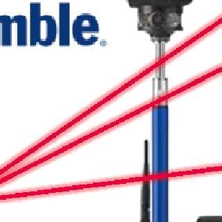


26 GFRP Exterior Panels (Glass Fiber Reinforced Polymer) Design/Coordination/De tailing & Fabrication/Placement Designed GFRP panels for fabricator Modeled outline of GFRP panels for coordination with structural frame Many conflicts were found during coordination prior to fabrication of GFRP panels 52 Trimble RTS Layout GFRP Layout Points for GFRP 53 26


27 Internal Benefits BIM in the Field Accurate Model Data Used Directly in the Field 54 CIP: 2 weeks ahead of schedule 21.6% of materials savings = $104,306 Zero RFI RFI Savings: 97, ,549 Steel: 8 weeks ahead of schedule $49,000 reduction in detailing costs $250,000 materials savings 2 RFI + 0 Change Orders Schedule: 10 weeks Costs: $600,

28


29

30 60 Thank you 61 30