AIRCRAFT HANGAR SKYLARK FIELD SECTION METAL BUILDING SYSTEMS PART 1 - GENERAL 1.1 RELATED DOCUMENTS
|
|
|
- Gladys Walters
- 5 years ago
- Views:
Transcription
1
2

3
4 AIRCRAFT HANGAR SKYLARK FIELD SECTION METAL BUILDING SYSTEMS PART 1 - GENERAL 1.1 RELATED DOCUMENTS A. Drawings and general provisions of the Contract, including General and Supplementary Conditions and Division 01 Specification Sections, apply to this Section. 1.2 SUMMARY A. Section Includes: 1. Structural-steel framing. 2. Metal roof panels. 3. Metal wall panels. 4. Foam-insulation-core metal wall panels Thermal insulation Accessories. B. Related Sections: 1. Section "Overhead Coiling Doors." 2. Section Fixed Louvers. 3. Section Aluminum Windows. 4. Section Hollow Metal Doors and Frames. 5. Section Vertically Bi-Fold Hangar Door. 1.3 DEFINITIONS A. Terminology Standard: See MBMA's "Metal Building Systems Manual" for definitions of terms for metal building system construction not otherwise defined in this Section or in referenced standards. 1.4 ACTION SUBMITTALS A. Product Data: For each type of metal building system component. Include construction details, material descriptions, dimensions of individual components and profiles, and finishes for the following: 1. Structural-steel-framing system. 2. Metal roof panels. 3. Metal wall panels. 4. Insulation and vapor retarder facings. 5. Flashing and trim. 6. Accessories. Jacobs F8Y METAL BUILDING SYSTEMS 08/24/12 Addendum 1
5 AIRCRAFT HANGAR SKYLARK FIELD B. Shop Drawings: For the following metal building system components. Include plans, elevations, sections, details, and attachments to other work. 1. Anchor-Bolt Plans: Submit anchor-bolt plans and templates before foundation work begins. Include location, diameter, and projection of anchor bolts required to attach metal building to foundation. Indicate column reactions at each location. 2. Structural-Framing Drawings: Show complete fabrication of primary and secondary framing; include provisions for openings. Indicate welds and bolted connections, distinguishing between shop and field applications. Include transverse cross-sections. 3. Metal Roof and Wall Panel Layout Drawings: Show layouts of metal panels including methods of support. Include details of edge conditions, joints, panel profiles, corners, anchorages, trim, flashings, closures, and special details. Distinguish between factoryand field-assembled work; show locations of exposed fasteners. a. Show roof-mounted items including penetrations, and items mounted on the roof. b. Show wall-mounted items including doors, windows, louvers, and lighting fixtures. 4. Accessory Drawings: Include details of the following items, at a scale of not less than 1-1/2 inches per 12 inches: a. Flashing and trim. b. Gutters. c. Downspouts. d. Louvers. C. Samples for Initial Selection: For units with factory-applied color finish. D. Samples for Verification: For each type of exposed finish required, prepared on Samples of sizes indicated below: 1. Metal Panels: Nominal 12 inches long by actual panel width. Include fasteners, closures, and other exposed panel accessories. 2. Flashing and Trim: Nominal 12 inches long. Include fasteners and other exposed accessories. 3. Vapor-Retarder Facings: Nominal 6-inch-square Samples. 4. Accessories: Nominal 12-inch-long Samples for each type of accessory. E. Delegated-Design Submittal: For metal building systems indicated to comply with performance requirements and design criteria, including analysis data signed and sealed by the qualified professional engineer responsible for their preparation. 1.5 INFORMATIONAL SUBMITTALS A. Qualification Data: For qualified erector, manufacturer, professional engineer, and testing agency. B. Welding certificates. Jacobs F8Y METAL BUILDING SYSTEMS 08/24/12 Addendum 1
6 AIRCRAFT HANGAR SKYLARK FIELD C. Metal Building System Certificates: For each type of metal building system, from manufacturer. 1. Letter of Design Certification: Signed and sealed by a qualified professional engineer. Include the following: a. Name and location of Project. b. Order number. c. Name of manufacturer. d. Name of Contractor. e. Building dimensions including width, length, height, and roof slope. f. Indicate compliance with AISC standards for hot-rolled steel and AISI standards for cold-rolled steel, including edition dates of each standard. g. Governing building code and year of edition. h. Design Loads: Include dead load, roof live load, collateral loads, roof snow load, deflection, wind loads/speeds and exposure, seismic design category or effective peak velocity-related acceleration/peak acceleration, and auxiliary loads. i. Load Combinations: Indicate that loads were applied acting simultaneously with concentrated loads, according to governing building code. j. Building-Use Category: Indicate category of building use and its effect on load importance factors. k. AISC Certification for Category MB: Include statement that metal building system and components were designed and produced in an AISC-Certified Facility by an AISC-Certified Manufacturer. D. Erector Certificates: For each product, from manufacturer. E. Manufacturer Certificates: For each product, from manufacturer. F. Material Test Reports: For each of the following products: 1. Structural steel including chemical and physical properties. 2. Bolts, nuts, and washers including mechanical properties and chemical analysis. 3. Tension-control, high-strength, bolt-nut-washer assemblies. 4. Shop primers. 5. Nonshrink grout. G. Product Test Reports: Based on evaluation of comprehensive tests performed by manufacturer and witnessed by a qualified testing agency, for insulation and vapor-retarder facings. Include reports for thermal resistance, fire-test-response characteristics, water-vapor transmission, and water absorption. H. Source quality-control reports. I. Field quality-control reports. J. Surveys: Show final elevations and locations of major members. Indicate discrepancies between actual installation and the Contract Documents. Have surveyor who performed surveys certify their accuracy. K. Warranties: Sample of special warranties. Jacobs F8Y METAL BUILDING SYSTEMS 08/24/12 Addendum 1
7 AIRCRAFT HANGAR SKYLARK FIELD 1.6 CLOSEOUT SUBMITTALS A. Maintenance Data: For metal panel finishes to include in maintenance manuals. 1.7 QUALITY ASSURANCE A. Manufacturer Qualifications: A qualified manufacturer and member of MBMA. 1. AISC Certification for Category MB: An AISC-Certified Manufacturer that designs and produces metal building systems and components in an AISC-Certified Facility. 2. Engineering Responsibility: Preparation of Shop Drawings and comprehensive engineering analysis by a qualified professional engineer. B. Land Surveyor Qualifications: A professional land surveyor who practices in jurisdiction where Project is located and who is experienced in providing surveying services of the kind indicated. C. Erector Qualifications: An experienced erector who specializes in erecting and installing work similar in material, design, and extent to that indicated for this Project and who is acceptable to manufacturer. D. Testing Agency Qualifications: Qualified according to ASTM E 329 for testing indicated. E. Source Limitations: Obtain metal building system components, including primary and secondary framing and metal panel assemblies, from single source from single manufacturer. F. Welding Qualifications: Qualify procedures and personnel according to the following: 1. AWS D1.1/D1.1M, "Structural Welding Code - Steel." 2. AWS D1.3, "Structural Welding Code - Sheet Steel." G. Structural Steel: Comply with AISC 360, "Specification for Structural Steel Buildings," for design requirements and allowable stresses. H. Cold-Formed Steel: Comply with AISI's "North American Specification for the Design of Cold-Formed Steel Structural Members" for design requirements and allowable stresses. I. Preinstallation Conference: Conduct conference at Project site. 1. Review methods and procedures related to metal building systems including, but not limited to, the following: a. Condition of foundations and other preparatory work performed by other trades. b. Structural load limitations. c. Construction schedule. Verify availability of materials and erector's personnel, equipment, and facilities needed to make progress and avoid delays. d. Required tests, inspections, and certifications. e. Unfavorable weather and forecasted weather conditions. 2. Review methods and procedures related to metal roof panel assemblies including, but not limited to, the following: Jacobs F8Y METAL BUILDING SYSTEMS 08/24/12 Addendum 1
8 AIRCRAFT HANGAR SKYLARK FIELD a. Compliance with requirements for purlin and rafter conditions, including flatness and attachment to structural members. b. Structural limitations of purlins and rafters during and after roofing. c. Flashings, special roof details, roof drainage, roof penetrations, equipment curbs, and condition of other construction that will affect metal roof panels. d. Temporary protection requirements for metal roof panel assembly during and after installation. e. Roof observation and repair after metal roof panel installation. 3. Review methods and procedures related to metal wall panel assemblies including, but not limited to, the following: a. Compliance with requirements for support conditions, including alignment between and attachment to structural members. b. Structural limitations of girts and columns during and after wall panel installation. c. Flashings, special siding details, wall penetrations, openings, and condition of other construction that will affect metal wall panels. d. Temporary protection requirements for metal wall panel assembly during and after installation. e. Wall observation and repair after metal wall panel installation. 1.8 DELIVERY, STORAGE, AND HANDLING A. Deliver components, sheets, panels, and other manufactured items so as not to be damaged or deformed. Package metal panels for protection during transportation and handling. B. Unload, store, and erect metal panels in a manner to prevent bending, warping, twisting, and surface damage. C. Stack metal panels horizontally on platforms or pallets, covered with suitable weathertight and ventilated covering. Store metal panels to ensure dryness, with positive slope for drainage of water. Do not store metal panels in contact with other materials that might cause staining, denting, or other surface damage. 1.9 PROJECT CONDITIONS A. Weather Limitations: Proceed with installation only when weather conditions permit metal panels to be installed according to manufacturers' written instructions and warranty requirements. B. Field Measurements: 1. Established Dimensions for Foundations: Comply with established dimensions on approved anchor-bolt plans, establishing foundation dimensions and proceeding with fabricating structural framing without field measurements. Coordinate anchor-bolt installation to ensure that actual anchorage dimensions correspond to established dimensions. 2. Established Dimensions for Metal Panels: Where field measurements cannot be made without delaying the Work, either establish framing and opening dimensions and proceed Jacobs F8Y METAL BUILDING SYSTEMS 08/24/12 Addendum 1
9 AIRCRAFT HANGAR SKYLARK FIELD with fabricating metal panels without field measurements, or allow for field trimming metal panels. Coordinate construction to ensure that actual building dimensions, locations of structural members, and openings correspond to established dimensions COORDINATION A. Coordinate sizes and locations of concrete foundations and casting of anchor-bolt inserts into foundation walls and footings. Concrete, reinforcement, and formwork requirements are specified in Section "Cast-in-Place Concrete." B. Coordinate metal panel assemblies with rain drainage work, flashing, trim, and construction of supports and other adjoining work to provide a leakproof, secure, and noncorrosive installation WARRANTY A. Special Warranty on Metal Panel Finishes: Manufacturer's standard form in which manufacturer agrees to repair finish or replace metal panels that show evidence of deterioration of factory-applied finishes within specified warranty period. 1. Exposed Panel Finish: Deterioration includes, but is not limited to, the following: a. Color fading more than 5 Hunter units when tested according to ASTM D b. Chalking in excess of a No. 8 rating when tested according to ASTM D c. Cracking, checking, peeling, or failure of paint to adhere to bare metal. 2. Finish Warranty Period: 20 years from date of Substantial Completion. B. Special Weathertightness Warranty for Standing-Seam Metal Roof Panels: Manufacturer's standard form in which manufacturer agrees to repair or replace standing-seam metal roof panel assemblies that leak or otherwise fail to remain weathertight within specified warranty period. 1. Warranty Period: 20 years from date of Substantial Completion. PART 2 - PRODUCTS 2.1 MANUFACTURERS A. Manufacturers: Subject to compliance with requirements, available manufacturers offering products that may be incorporated into the Work include, but are not limited to, the following: 1. Butler Manufacturing Company; a BlueScope Steel company. 2. Ceco Building Systems; Division of NCI Building Systems, L.P. 3. Mesco Building Solutions; Division of NCI Building Systems, L.P. 4. VP Buildings; a United Dominion company. 5. Whirlwind Building Systems. 6. General Steel 7. MBCI Jacobs F8Y METAL BUILDING SYSTEMS 08/24/12 Addendum 1
10 2.2 METAL BUILDING SYSTEMS AIRCRAFT HANGAR SKYLARK FIELD A. Description: Provide a complete, integrated set of metal building system manufacturer's standard mutually dependent components and assemblies that form a metal building system capable of withstanding structural and other loads, thermally induced movement, and exposure to weather without failure or infiltration of water into building interior. 1. Provide metal building system of size and with bay spacings, roof slopes, and spans indicated. B. Primary-Frame Type: 1. Rigid Clear Span: Solid-member, structural-framing system without interior columns. C. End-Wall Framing: Manufacturer's standard, for buildings not required to be expandable, consisting of primary frame, capable of supporting one-half of a bay design load, and end-wall columns. D. Secondary-Frame Type: Manufacturer's standard purlins and joists and exterior-framed (bypass) girts. E. Eave Height: 34 feet Manufacturer's standard height, as indicated by nominal height on Drawings. F. Bay Spacing: As indicated on drawings. G. Roof Slope: 1 inch per 12 inches. H. Roof System: Manufacturer's standard trapezoidal-rib, standing-seam metal roof panels with field-installed insulation. Profile as indicated on drawings. I. Exterior Wall System: Manufacturer's standard flat wall panel with concealed-fastener metal wall panels. Profile as indicated on drawings. J. Exterior Wall System: Manufacturer's standard foam-insulation-core metal wall panels. Profile as indicated on drawings. 2.3 METAL BUILDING SYSTEM PERFORMANCE A. Delegated Design: Design metal building system, including comprehensive engineering analysis by a qualified professional engineer, using performance requirements and design criteria indicated. B. Structural Performance: Metal building systems shall withstand the effects of gravity loads and the following loads and stresses within limits and under conditions indicated according to procedures in MBMA's "Metal Building Systems Manual." 1. Design Loads: As indicated on Drawings. 2. Design Loads: As required by MBMA's "Metal Building Systems Manual" and ASCE/SEI 7. Jacobs F8Y METAL BUILDING SYSTEMS 08/24/12 Addendum 1
11 AIRCRAFT HANGAR SKYLARK FIELD 3. Deflection Limits: Design metal building system assemblies to withstand design loads with deflections no greater than the following: a. Purlins and Rafters: Vertical deflection of 1/180 of the span. b. Girts: Horizontal deflection of 1/180 of the span. c. Metal Roof Panels: Vertical deflection of 1/180 of the span. d. Metal Wall Panels: Horizontal deflection of 1/180 of the span. e. Bi-fold Door Side Columns: Horizontal deflection of 1/120 of the span. f. Design secondary-framing system to accommodate deflection of primary framing and construction tolerances, and to maintain clearances at openings. 4. Drift Limits: Engineer building structure to withstand design loads with drift limits no greater than the following: a. Lateral Drift: Maximum of 1/120 of the building height. 5. Metal panel assemblies shall withstand the effects of gravity loads and loads and stresses within limits and under conditions indicated according to ASTM E C. Seismic Performance: Metal building systems shall withstand the effects of earthquake motions determined according to ASCE/SEI 7. D. Thermal Movements: Allow for thermal movements resulting from the following maximum change (range) in ambient and surface temperatures by preventing buckling, opening of joints, overstressing of components, failure of joint sealants, failure of connections, and other detrimental effects. Base engineering calculations on surface temperatures of materials due to both solar heat gain and nighttime-sky heat loss. 1. Temperature Change (Range): 120 deg F, ambient; 180 deg F, material surfaces. E. Air Infiltration for Metal Roof Panels: Air leakage through assembly of not more than 0.06 cfm/sq. ft. of roof area when tested according to ASTM E 1680 at negative test-pressure difference of 1.57 lbf/sq. ft. F. Air Infiltration for Metal Wall Panels: Air leakage through assembly of not more than 0.06 cfm/sq. ft. of wall area when tested according to ASTM E 283 at static-air-pressure difference of 1.57 lbf/sq. ft. G. Water Penetration for Metal Roof Panels: No water penetration when tested according to ASTM E 1646 at test-pressure difference of 2.86 lbf/sq. ft. H. Water Penetration for Metal Wall Panels: No water penetration when tested according to ASTM E 331 at a wind-load design pressure of not less than 2.86 lbf/sq. ft. I. Wind-Uplift Resistance: Provide metal roof panel assemblies that comply with UL 580 for Class 90. J. Thermal Performance: Provide insulated metal panel assemblies with the following maximum U-factors and minimum R-values for opaque elements when tested according to ASTM C 1363 or ASTM C 518: Jacobs F8Y METAL BUILDING SYSTEMS 08/24/12 Addendum 1
12 1. Metal Roof Panel Assemblies: a. R-Value: Metal Wall Panel Assemblies: a. R-Value: 11. AIRCRAFT HANGAR SKYLARK FIELD 2.4 STRUCTURAL-STEEL FRAMING A. Primary Framing: Manufacturer's standard primary-framing system, designed to withstand required loads and specified requirements. Primary framing includes transverse frames; rafter, rake; sidewall, intermediate, end-wall, and corner columns; and wind bracing. 1. General: Provide frames with attachment plates, bearing plates, and splice members. Factory drill for field-bolted assembly. Provide frame span and spacing indicated. a. Slight variations in span and spacing may be acceptable if necessary to comply with manufacturer's standard, as approved by Architect. 2. Rigid Clear-Span Frames: I-shaped frame sections fabricated from shop-welded, built-up steel plates or structural-steel shapes. Interior columns are not permitted. 3. Frame Configuration: Single gable. 4. Exterior Column Type: Tapered. 5. Rafter Type: Tapered. B. End-Wall Framing: Manufacturer's standard primary end-wall framing fabricated for fieldbolted assembly to comply with the following: 1. End-Wall and Corner Columns: I-shaped sections fabricated from structural-steel shapes; shop-welded, built-up steel plates; or C-shaped, cold-formed, structural-steel sheet. 2. End-Wall Rafters: C-shaped, cold-formed, structural-steel sheet; or I-shaped sections fabricated from shop-welded, built-up steel plates or structural-steel shapes. C. Secondary Framing: Manufacturer's standard secondary framing, including purlins, girts, eave struts, flange bracing, base members, gable angles, clips, headers, jambs, and other miscellaneous structural members. Unless otherwise indicated, fabricate framing from either cold-formed, structural-steel sheet or roll-formed, metallic-coated steel sheet, prepainted with coil coating, to comply with the following: 1. Purlins: C- or Z-shaped sections; fabricated from built-up steel plates, steel sheet, or structural-steel shapes; minimum 2-1/2-inch- wide flanges. a. Depth: As indicated, 8 inches. 2. Girts: C- or Z-shaped sections; fabricated from built-up steel plates, steel sheet, or structural-steel shapes. Form ends of Z-sections with stiffening lips angled 40 to 50 degrees from flange, with minimum 2-1/2-inch- wide flanges. a. Depth: As indicated, 8 inches. Jacobs F8Y METAL BUILDING SYSTEMS 08/24/12 Addendum 1
13 AIRCRAFT HANGAR SKYLARK FIELD 3. Eave Struts: Unequal-flange, C-shaped sections; fabricated from built-up steel plates, steel sheet, or structural-steel shapes; to provide adequate backup for metal panels. 4. Flange Bracing: Minimum 2-by-2-by-1/8-inch structural-steel angles or 1-inch diameter, cold-formed structural tubing to stiffen primary-frame flanges. 5. Sag Bracing: Minimum 1-by-1-by-1/8-inch structural-steel angles. 6. Base or Sill Angles: Minimum 3-by-2-inch zinc-coated (galvanized) steel sheet. 7. Purlin and Girt Clips: Manufacturer's standard clips fabricated from steel sheet. Provide galvanized clips where clips are connected to galvanized framing members. 8. Secondary End-Wall Framing: Manufacturer's standard sections fabricated from zinccoated (galvanized) steel sheet. 9. Framing for Openings: Channel shapes; fabricated from cold-formed, structural-steel sheet or structural-steel shapes. Frame head and jamb of door openings and head, jamb, and sill of other openings. 10. Miscellaneous Structural Members: Manufacturer's standard sections fabricated from cold-formed, structural-steel sheet; built-up steel plates; or zinc-coated (galvanized) steel sheet; designed to withstand required loads. D. Bracing: Provide adjustable wind bracing as follows: 1. Rods: ASTM A 36/A 36M; ASTM A 572/A 572M, Grade 50; or ASTM A 529/A 529M, Grade 50; minimum 1/2-inch- diameter steel; threaded full length or threaded a minimum of 6 inches at each end. 2. Angles: Fabricated from structural-steel shapes to match primary framing, of size required to withstand design loads. 3. Rigid Portal Frames: Fabricated from shop-welded, built-up steel plates or structuralsteel shapes to match primary framing; of size required to withstand design loads. 4. Bracing: Provide wind bracing using any method specified above, at manufacturer's option. E. Bolts: Provide plain-finish bolts for structural-framing components that are primed or finish painted. Provide zinc-plated or hot-dip galvanized bolts for structural-framing components that are galvanized. F. Materials: 1. W-Shapes: ASTM A 992/A 992M; ASTM A 572/A 572M, Grade 50 or 55; or ASTM A 529/A 529M, Grade 50 or Channels, Angles, M-Shapes, and S-Shapes: ASTM A 36/A 36M; ASTM A 572/A 572M, Grade 50 or 55; or ASTM A 529/A 529M, Grade 50 or Plate and Bar: ASTM A 36/A 36M; ASTM A 572/A 572M, Grade 50 or 55; or ASTM A 529/A 529M, Grade 50 or Steel Pipe: ASTM A 53/A 53M, Type E or S, Grade B. 5. Cold-Formed Hollow Structural Sections: ASTM A 500, Grade B or C, structural tubing. 6. Structural-Steel Sheet: Hot-rolled, ASTM A 1011/A 1011M, Structural Steel (SS), Grades 30 through 55, or High-Strength Low-Alloy Steel (HSLAS), Grades 45 through 70; or cold-rolled, ASTM A 1008/A 1008M, Structural Steel (SS), Grades 25 through 80, or High-Strength Low-Alloy Steel (HSLAS), Grades 45 through Metallic-Coated Steel Sheet: ASTM A 653/A 653M, Structural Steel (SS), Grades 33 through 80 or High-Strength Low-Alloy Steel (HSLAS), Grades 50 through 80; with G60 coating designation; mill phosphatized. Jacobs F8Y METAL BUILDING SYSTEMS 08/24/12 Addendum 1
14 AIRCRAFT HANGAR SKYLARK FIELD 8. Metallic-Coated Steel Sheet Prepainted with Coil Coating: Steel sheet, metallic coated by the hot-dip process and prepainted by the coil-coating process to comply with ASTM A 755/A 755M. a. Zinc-Coated (Galvanized) Steel Sheet: ASTM A 653/A 653M, Structural Steel (SS), Grades 33 through 80 or High-Strength Low-Alloy Steel (HSLAS), Grades 50 through 80; with G90 coating designation. b. Aluminum-Zinc Alloy-Coated Steel Sheet: ASTM A 792/A 792M, Structural Steel (SS), Grade 50 or 80; with Class AZ50 coating. 9. Non-High-Strength Bolts, Nuts, and Washers: ASTM A 307, Grade A, carbon-steel, hex-head bolts; ASTM A 563 carbon-steel hex nuts; and ASTM F 844 plain (flat) steel washers. a. Finish: Hot-dip zinc coating, ASTM A 153/A 153M, Class C. 10. High-Strength Bolts, Nuts, and Washers: ASTM A 325, Type 1, heavy-hex steel structural bolts; ASTM A 563 heavy-hex carbon-steel nuts; and ASTM F 436 hardened carbon-steel washers. a. Finish: Hot-dip zinc coating, ASTM A 153/A 153M, Class C. 11. High-Strength Bolts, Nuts, and Washers: ASTM A 490, Type 1, heavy-hex steel structural bolts or tension-control, bolt-nut-washer assemblies with spline ends; ASTM A 563 heavy-hex carbon-steel nuts; and ASTM F 436 hardened carbon-steel washers, plain. 12. Tension-Control, High-Strength Bolt-Nut-Washer Assemblies: ASTM F 1852, Type 1, heavy-hex-head steel structural bolts with spline ends. a. Finish: Mechanically deposited zinc coating, ASTM B 695, Class Unheaded Anchor Rods: ASTM F 1554, Grade 55. a. Configuration: Straight. b. Nuts: ASTM A 563 heavy-hex carbon steel. c. Plate Washers: ASTM A 36/A 36M carbon steel. d. Washers: ASTM F 436 hardened carbon steel. e. Finish: Hot-dip zinc coating, ASTM A 153/A 153M, Class C. 14. Threaded Rods: ASTM A 193/A 193M ASTM A 572/A 572M, Grade 50 ASTM A 36/A 36M or ASTM A 307, Grade A. a. Nuts: ASTM A 563 heavy-hex carbon steel. b. Washers: ASTM F 436 hardened carbon steel. c. Finish: Hot-dip zinc coating, ASTM A 153/A 153M, Class C. G. Finish: Factory primed. Apply specified primer immediately after cleaning and pretreating. 1. Apply primer to primary and secondary framing to a minimum dry film thickness of 1 mil. Jacobs F8Y METAL BUILDING SYSTEMS 08/24/12 Addendum 1
15 AIRCRAFT HANGAR SKYLARK FIELD a. Prime secondary framing formed from uncoated steel sheet to a minimum dry film thickness of 0.5 mil on each side. 2. Prime galvanized members with specified primer after phosphoric acid pretreatment. 3. Primer: SSPC-Paint 15, Type I, red oxide. 2.5 METAL ROOF PANELS A. Trapezoidal-Rib, Standing-Seam Metal Roof Panels: Formed with raised trapezoidal ribs at panel edges and flat pan between ribs; designed for sequential installation by mechanically attaching panels to supports using concealed clips located under one side of panels and engaging opposite edge of adjacent panels. 1. Material: Aluminum-zinc alloy-coated steel sheet, 24 gauge nominal thickness. a. Exterior Finish: Fluoropolymer. b. Color: As indicated on drawings. 2. Clips: Manufacturer's standard, floating type to accommodate thermal movement; fabricated from stainless-steel sheet. 3. Joint Type: Mechanically seamed, double folded. 4. Panel Coverage: 24 inches. 5. Panel Height: 2 inches. 6. Uplift Rating: UL 90. B. Finishes: 1. Exposed Coil-Coated Finish: a. Three-Coat Fluoropolymer: AAMA 621. Fluoropolymer finish containing not less than 70 percent PVDF resin by weight in both color coat and clear topcoat. Prepare, pretreat, and apply coating to exposed metal surfaces to comply with coating and resin manufacturers' written instructions. 2. Concealed Finish: Apply pretreatment and manufacturer's standard white or lightcolored acrylic or polyester backer finish, consisting of prime coat and wash coat with a minimum total dry film thickness of 0.5 mil. 2.6 METAL WALL PANELS A. Concealed-Fastener Metal Wall Panels: Formed with vertical panel edges and flush surface; with flush joint between panels; with 1-inch- wide flange for attaching interior finish; designed to be installed by lapping and interconnecting side edges of adjacent panels and mechanically attaching through panel to supports using concealed fasteners and factory-applied sealant in side laps. 1. Material: Zinc-coated (galvanized) steel sheet, 26 gauge nominal thickness. a. Exterior Finish: Fluoropolymer. b. Color: As indicated on drawings. Jacobs F8Y METAL BUILDING SYSTEMS 08/24/12 Addendum 1
16 2. Panel Coverage: 16 inches. 3. Panel Thickness: 2 inches. AIRCRAFT HANGAR SKYLARK FIELD 2.7 FOAM-INSULATION-CORE METAL WALL PANELS A. Description: Provide factory-formed and -assembled, metal wall panels fabricated from two metal facing sheets and an insulation core foamed in place during fabrication, with joints between panels designed to form weathertight seals for vertically bi-fold hangar door sheathing. Include accessories required for weathertight installation. 1. Concealed-Fastener, Foam-Insulation-Core Metal Wall Panels: Formed with tongue-andgroove panel edges; designed for sequential installation by interlocking panel edges and mechanically attaching panels to supports using concealed clips or fasteners. a. Facings: Fabricate panel with exterior and interior facings of same material and thickness. b. Exterior Surface: Smooth, flat. c. Panel Coverage: 36 inches nominal. d. Panel Thickness: 2 inches. e. Thermal-Resistance Value: R-15. B. Foamed-in-Place Polyurethane Core: The core shall be poured-in-place non-cfc, blister free polyurethane foam with the following properties: 1. Closed Cell Structure: 92 percent. 2. Minimum Density: 2.0 lbs/ft3. 3. Compressive Strength: 22 psi. 4. Tensile Strength: 33 psi. 5. Shear Strength: 21 psi. C. Physical Properties 1. Structural a. The design load deflection criteria shall be verified from tests per ASTM E72 Air Bag Method using a 20 psf simulated wind load. A deflection limit ofui80 shall apply. 2. Thermal a. When tested in accordance with ASTM C5 18 the panels shall provide a K-factor of.127 btu/ft2/hr/degrees F at a 40 degrees F mean temperature. 3. Vapor Retardation a. Air infiltration shall not exceed.06 cfm/ft2 of wall area when tested per ASTM E283 at a static pressure of 12.0 psf. b. Static Water Penetration: There shall be no uncontrolled water penetration through the panel joints at a static pressure of 20.0 psf when tested per ASTM E331. Jacobs F8Y METAL BUILDING SYSTEMS 08/24/12 Addendum 1
17 4. Fire AIRCRAFT HANGAR SKYLARK FIELD c. Dynamic Water Penetration: There shall be no uncontrolled water penetration through the panel joints when subjected to a 95 mph slipstream air flow and application of water for a fifteen minute period in accordance with AAMA d. Condensation Resistance Factor: The minimum condensation resistance factor of the panel shall be 92 when tested in general accordance with AAMA a. Factory Mutual Research Corporation (FMRC) Standard 4880, Room Fire Test Procedure: Panels shall meet the requirements for Class 1 fire, nonload bearing architectural panels without requiring automatic sprinkler protection of the panels. b. Surface Burning Characteristics: The insulated core shall have been tested in accordance with ASTM E84 for surface burning characteristics. The core shall have a maximum flame spread of 20 and a maximum smoke developed rating of Bond Strength a. Fatigue Test: The panel shall withstand deflection cycling at L180 to two million alternate cycles with no evidence of delamination, core cracking or permanent bowing THERMAL INSULATION A. Unfaced Metal Building Insulation: ASTM C 991, Type I, or NAIMA 202, glass-fiber-blanket insulation; 0.5-lb/cu. ft. density; 2-inch- wide, continuous, vapor-tight edge tabs; with a flamespread index of 25 or less. 1. Vapor-Retarder Facing: ASTM C 1136, with permeance not greater than 0.02 perm when tested according to ASTM E 96/E 96M, Desiccant Method. a. Composition: White polypropylene film facing and fiberglass-polyester-blend fabric backing. B. Retainer Strips: inch nominal-thickness, formed, metallic-coated steel or PVC retainer clips colored to match insulation facing. C. Vapor-Retarder Tape: Pressure-sensitive tape of type recommended by vapor-retarder manufacturer for sealing joints and penetrations in vapor retarder DOORS AND FRAMES A. Personnel Doors and Frames: As specified in Section "Hollow Metal Doors and Frames." WINDOWS A. Aluminum Windows: As specified in Section "Aluminum Windows." Jacobs F8Y METAL BUILDING SYSTEMS 08/24/12 Addendum 1
18 AIRCRAFT HANGAR SKYLARK FIELD B. Glazing: As specified in Section "Glazing." ACCESSORIES A. General: Provide accessories as standard with metal building system manufacturer and as specified. Fabricate and finish accessories at the factory to greatest extent possible, by manufacturer's standard procedures and processes. Comply with indicated profiles and with dimensional and structural requirements. 1. Form exposed sheet metal accessories that are without excessive oil-canning, buckling, and tool marks and that are true to line and levels indicated, with exposed edges folded back to form hems. B. Roof Panel Accessories: Provide components required for a complete metal roof panel assembly including copings, fasciae, corner units, ridge closures, clips, sealants, gaskets, fillers, closure strips, and similar items. Match material and finish of metal roof panels unless otherwise indicated. 1. Closures: Provide closures at eaves and ridges, fabricated of same material as metal roof panels. 2. Clips: Manufacturer's standard, formed from steel sheet, designed to withstand negativeload requirements. 3. Cleats: Manufacturer's standard, mechanically seamed cleats formed from steel sheet. 4. Backing Plates: Provide metal backing plates at panel end splices, fabricated from material recommended by manufacturer. 5. Closure Strips: Closed-cell, expanded, cellular, rubber or crosslinked, polyolefin-foam or closed-cell laminated polyethylene; minimum 1-inch- thick, flexible closure strips; cut or premolded to match metal roof panel profile. Provide closure strips where indicated or necessary to ensure weathertight construction. 6. Thermal Spacer Blocks: Where metal panels attach directly to purlins, provide thermal spacer blocks of thickness required to provide 1-inch standoff; fabricated from extruded polystyrene. C. Wall Panel Accessories: Provide components required for a complete metal wall panel assembly including copings, fasciae, mullions, sills, corner units, clips, sealants, gaskets, fillers, closure strips, and similar items. Match material and finish of metal wall panels unless otherwise indicated. 1. Closures: Provide closures at eaves and rakes, fabricated of same material as metal wall panels. 2. Backing Plates: Provide metal backing plates at panel end splices, fabricated from material recommended by manufacturer. 3. Closure Strips: Closed-cell, expanded, cellular, rubber or crosslinked, polyolefin-foam or closed-cell laminated polyethylene; minimum 1-inch- thick, flexible closure strips; cut or premolded to match metal wall panel profile. Provide closure strips where indicated or necessary to ensure weathertight construction. D. Flashing and Trim: Formed from inch nominal-thickness, metallic-coated steel sheet or aluminum-zinc alloy-coated steel sheet prepainted with coil coating; finished to match adjacent metal panels. Jacobs F8Y METAL BUILDING SYSTEMS 08/24/12 Addendum 1
19 AIRCRAFT HANGAR SKYLARK FIELD E. Gutters: Formed from inch nominal-thickness, metallic-coated steel sheet or aluminumzinc alloy-coated steel sheet prepainted with coil coating; finished to match roof fascia and rake trim. Match profile of gable trim, complete with end pieces, outlet tubes, and other special pieces as required. Fabricate in minimum 96-inch- long sections, sized according to SMACNA's "Architectural Sheet Metal Manual." 1. Gutter Supports: Fabricated from same material and finish as gutters. 2. Strainers: Bronze, copper, or aluminum wire ball type at outlets. F. Downspouts: Formed from inch nominal-thickness, zinc-coated (galvanized) steel sheet or aluminum-zinc alloy-coated steel sheet prepainted with coil coating; finished to match metal wall panels. Fabricate in minimum 10-foot- long sections, complete with formed elbows and offsets. 1. Mounting Straps: Fabricated from same material and finish as gutters. G. Louvers: As specified in Section Fixed Louver. H. Pipe Flashing: Premolded, EPDM pipe collar with flexible aluminum ring bonded to base. I. Materials: 1. Fasteners: Self-tapping screws, bolts, nuts, self-locking rivets and bolts, end-welded studs, and other suitable fasteners designed to withstand design loads. Provide fasteners with heads matching color of materials being fastened by means of plastic caps or factory-applied coating. a. Fasteners for Metal Roof Panels: Self-drilling, Type 410 stainless-steel or selftapping, Type 304 stainless-steel or zinc-alloy-steel hex washer head, with EPDM washer under heads of fasteners bearing on weather side of metal panels. b. Fasteners for Metal Wall Panels: Self-drilling, Type 410 stainless-steel or selftapping, Type 304 stainless-steel or zinc-alloy-steel hex washer head, with EPDM sealing washers bearing on weather side of metal panels. c. Fasteners for Flashing and Trim: Blind fasteners or self-drilling screws with hex washer head. d. Blind Fasteners: High-strength aluminum or stainless-steel rivets. 2. Corrosion-Resistant Coating: Cold-applied asphalt mastic, compounded for 15-mil dry film thickness per coat. Provide inert-type noncorrosive compound free of asbestos fibers, sulfur components, and other deleterious impurities. 3. Nonmetallic, Shrinkage-Resistant Grout: ASTM C 1107, factory-packaged, nonmetallic aggregate grout, noncorrosive, nonstaining, mixed with water to consistency suitable for application and a 30-minute working time. 4. Metal Panel Sealants: a. Sealant Tape: Pressure-sensitive, 100 percent solids, gray polyisobutylenecompound sealant tape with release-paper backing. Provide permanently elastic, nonsag, nontoxic, nonstaining tape of manufacturer's standard size. b. Joint Sealant: ASTM C 920; one-part elastomeric polyurethane or polysulfide; of type, grade, class, and use classifications required to seal joints in metal panels and remain weathertight; and as recommended by metal building system manufacturer. Jacobs F8Y METAL BUILDING SYSTEMS 08/24/12 Addendum 1
20 SOURCE QUALITY CONTROL AIRCRAFT HANGAR SKYLARK FIELD A. Testing Agency: Owner will engage a qualified testing agency to evaluate product. B. Special Inspector: Owner will engage a qualified special inspector to perform the following tests and inspections and to submit reports. Special inspector will verify that manufacturer maintains detailed fabrication and quality-control procedures and will review the completeness and adequacy of those procedures to perform the Work. 1. Special inspections will not be required if fabrication is performed by manufacturer registered and approved by authorities having jurisdiction to perform such Work without special inspection. a. After fabrication, submit copy of certificate of compliance to authorities having jurisdiction, certifying that Work was performed according to Contract requirements. C. Testing: Test and inspect shop connections for metal buildings according to the following: 1. Bolted Connections: Shop-bolted connections shall be tested and inspected according to RCSC's "Specification for Structural Joints Using ASTM A 325 or A 490 Bolts." 2. Welded Connections: In addition to visual inspection, shop-welded connections shall be tested and inspected according to AWS D1.1/D1.1M and the following inspection procedures, at inspector's option: a. Liquid Penetrant Inspection: ASTM E 165. b. Magnetic Particle Inspection: ASTM E 709; performed on root pass and on finished weld. Cracks or zones of incomplete fusion or penetration will not be accepted. c. Ultrasonic Inspection: ASTM E 164. d. Radiographic Inspection: ASTM E 94. D. Product will be considered defective if it does not pass tests and inspections. E. Prepare test and inspection reports FABRICATION A. General: Design components and field connections required for erection to permit easy assembly. 1. Mark each piece and part of the assembly to correspond with previously prepared erection drawings, diagrams, and instruction manuals. 2. Fabricate structural framing to produce clean, smooth cuts and bends. Punch holes of proper size, shape, and location. Members shall be free of cracks, tears, and ruptures. B. Tolerances: Comply with MBMA's "Metal Building Systems Manual" for fabrication and erection tolerances. Jacobs F8Y METAL BUILDING SYSTEMS 08/24/12 Addendum 1
21 AIRCRAFT HANGAR SKYLARK FIELD C. Primary Framing: Shop fabricate framing components to indicated size and section, with baseplates, bearing plates, stiffeners, and other items required for erection welded into place. Cut, form, punch, drill, and weld framing for bolted field assembly. 1. Make shop connections by welding or by using high-strength bolts. 2. Join flanges to webs of built-up members by a continuous, submerged arc-welding process. 3. Brace compression flange of primary framing with steel angles or cold-formed structural tubing between frame web and purlin web or girt web, so flange compressive strength is within allowable limits for any combination of loadings. 4. Weld clips to frames for attaching secondary framing. 5. Shop Priming: Prepare surfaces for shop priming according to SSPC-SP 2. Shop prime primary framing with specified primer after fabrication. D. Secondary Framing: Shop fabricate framing components to indicated size and section by rollforming or break-forming, with baseplates, bearing plates, stiffeners, and other plates required for erection welded into place. Cut, form, punch, drill, and weld secondary framing for bolted field connections to primary framing. 1. Make shop connections by welding or by using non-high-strength bolts. 2. Shop Priming: Prepare uncoated surfaces for shop priming according to SSPC-SP 2. Shop prime uncoated secondary framing with specified primer after fabrication. E. Metal Panels: Fabricate and finish metal panels at the factory to greatest extent possible, by manufacturer's standard procedures and processes, as necessary to fulfill indicated performance requirements. Comply with indicated profiles and with dimensional and structural requirements. 1. Provide panel profile, including major ribs and intermediate stiffening ribs, if any, for full length of metal panel. PART 3 - EXECUTION 3.1 EXAMINATION A. Examine substrates, areas, and conditions, with erector present, for compliance with requirements for installation tolerances and other conditions affecting performance of the Work. B. Before erection proceeds, survey elevations and locations of concrete-bearing surfaces and locations of anchor rods, bearing plates, and other embedments to receive structural framing, with erector present, for compliance with requirements and metal building system manufacturer's tolerances. 1. Engage land surveyor to perform surveying. C. Proceed with erection only after unsatisfactory conditions have been corrected. Jacobs F8Y METAL BUILDING SYSTEMS 08/24/12 Addendum 1
22 AIRCRAFT HANGAR SKYLARK FIELD 3.2 PREPARATION A. Clean and prepare surfaces to be painted according to manufacturer's written instructions for each particular substrate condition. B. Provide temporary shores, guys, braces, and other supports during erection to keep structural framing secure, plumb, and in alignment against temporary construction loads and loads equal in intensity to design loads. Remove temporary supports when permanent structural framing, connections, and bracing are in place unless otherwise indicated. 3.3 ERECTION OF STRUCTURAL FRAMING A. Erect metal building system according to manufacturer's written erection instructions and erection drawings. B. Do not field cut, drill, or alter structural members without written approval from metal building system manufacturer's professional engineer. C. Set structural framing accurately in locations and to elevations indicated, according to AISC specifications referenced in this Section. Maintain structural stability of frame during erection. D. Base Plates: Clean concrete-bearing surfaces of bond-reducing materials, and roughen surfaces prior to setting plates. Clean bottom surface of plates. 1. Set plates for structural members on wedges, shims, or setting nuts as required. 2. Tighten anchor rods after supported members have been positioned and plumbed. Do not remove wedges or shims but, if protruding, cut off flush with edge of plate before packing with grout. 3. Promptly pack grout solidly between bearing surfaces and plates so no voids remain. Neatly finish exposed surfaces; protect grout and allow to cure. Comply with manufacturer's written installation instructions for shrinkage-resistant grouts. E. Align and adjust structural framing before permanently fastening. Before assembly, clean bearing surfaces and other surfaces that will be in permanent contact with framing. Perform necessary adjustments to compensate for discrepancies in elevations and alignment. 1. Level and plumb individual members of structure. 2. Make allowances for difference between temperature at time of erection and mean temperature when structure will be completed and in service. F. Primary Framing and End Walls: Erect framing level, plumb, rigid, secure, and true to line. Level baseplates to a true even plane with full bearing to supporting structures, set with doublenutted anchor bolts. Use grout to obtain uniform bearing and to maintain a level base-line elevation. Moist-cure grout for not less than seven days after placement. 1. Make field connections using high-strength bolts installed according to RCSC's "Specification for Structural Joints Using ASTM A 325 or A 490 Bolts" for bolt type and joint type specified. a. Joint Type: Snug tightened or pretensioned. Jacobs F8Y METAL BUILDING SYSTEMS 08/24/12 Addendum 1
23 AIRCRAFT HANGAR SKYLARK FIELD G. Secondary Framing: Erect framing level, plumb, rigid, secure, and true to line. Field bolt secondary framing to clips attached to primary framing. 1. Provide rake or gable purlins with tight-fitting closure channels and fasciae. 2. Locate and space wall girts to suit openings such as doors and windows. 3. Provide supplemental framing at entire perimeter of openings, including doors, windows, louvers, and other penetrations of roof and walls. H. Bracing: Install bracing in roof and sidewalls where indicated on erection drawings. 1. Tighten rod bracing to avoid sag. 2. Locate interior end-bay bracing only where indicated. I. Framing for Openings: Provide shapes of proper design and size to reinforce openings and to carry loads and vibrations imposed, including equipment furnished under mechanical and electrical work. Securely attach to structural framing. J. Erection Tolerances: Maintain erection tolerances of structural framing within AISC METAL PANEL INSTALLATION, GENERAL A. Examination: Examine primary and secondary framing to verify that structural-panel support members and anchorages have been installed within alignment tolerances required by manufacturer. 1. Examine roughing-in for components and systems penetrating metal panels, to verify actual locations of penetrations relative to seams before metal panel installation. B. General: Anchor metal panels and other components of the Work securely in place, with provisions for thermal and structural movement. 1. Field cut metal panels as required for doors, windows, and other openings. Cut openings as small as possible, neatly to size required, and without damage to adjacent metal panel finishes. a. Field cutting of metal panels by torch is not permitted unless approved in writing by manufacturer. 2. Install metal panels perpendicular to structural supports unless otherwise indicated. 3. Flash and seal metal panels with weather closures at perimeter of openings and similar elements. Fasten with self-tapping screws. 4. Locate and space fastenings in uniform vertical and horizontal alignment. 5. Locate metal panel splices over, but not attached to, structural supports with end laps in alignment. 6. Lap metal flashing over metal panels to allow moisture to run over and off the material. C. Lap-Seam Metal Panels: Install screw fasteners using power tools with controlled torque adjusted to compress EPDM washers tightly without damage to washers, screw threads, or metal panels. Install screws in predrilled holes. Jacobs F8Y METAL BUILDING SYSTEMS 08/24/12 Addendum 1
24 AIRCRAFT HANGAR SKYLARK FIELD 1. Arrange and nest side-lap joints so prevailing winds blow over, not into, lapped joints. Lap ribbed or fluted sheets one full rib corrugation. Apply metal panels and associated items for neat and weathertight enclosure. Avoid "panel creep" or application not true to line. D. Metal Protection: Where dissimilar metals contact each other or corrosive substrates, protect against galvanic action by painting contact surfaces with corrosion-resistant coating, by applying rubberized-asphalt underlayment to each contact surface, or by other permanent separation as recommended by metal roof panel manufacturer. E. Joint Sealers: Install gaskets, joint fillers, and sealants where indicated and where required for weatherproof performance of metal panel assemblies. Provide types of gaskets, fillers, and sealants indicated; or, if not indicated, provide types recommended by metal panel manufacturer. 1. Seal metal panel end laps with double beads of tape or sealant the full width of panel. Seal side joints where recommended by metal panel manufacturer. 2. Prepare joints and apply sealants to comply with requirements in Section "Joint Sealants." 3.5 METAL ROOF PANEL INSTALLATION A. General: Provide metal roof panels of full length from eave to ridge unless otherwise indicated or restricted by shipping limitations. 1. Install ridge caps as metal roof panel work proceeds. 2. Flash and seal metal roof panels with weather closures at eaves and rakes. Fasten with self-tapping screws. B. Standing-Seam Metal Roof Panels: Fasten metal roof panels to supports with concealed clips at each standing-seam joint, at location and spacing and with fasteners recommended by manufacturer. 1. Install clips to supports with self-drilling or self-tapping fasteners. 2. Install pressure plates at locations indicated in manufacturer's written installation instructions. 3. Snap Joint: Nest standing seams and fasten together by interlocking and completely engaging factory-applied sealant. 4. Seamed Joint: Crimp standing seams with manufacturer-approved motorized seamer tool so that clip, metal roof panel, and factory-applied sealant are completely engaged. 5. Rigidly fasten eave end of metal roof panels and allow ridge end free movement due to thermal expansion and contraction. Predrill panels for fasteners. 6. Provide metal closures at peaks, rake edges, rake walls, and each side of ridge caps. C. Metal Roof Panel Installation Tolerances: Shim and align metal roof panels within installed tolerance of 1/4 inch in 20 feet on slope and location lines as indicated and within 1/8-inch offset of adjoining faces and of alignment of matching profiles. Jacobs F8Y METAL BUILDING SYSTEMS 08/24/12 Addendum 1
25 AIRCRAFT HANGAR SKYLARK FIELD 3.6 METAL WALL PANEL INSTALLATION A. General: Install metal wall panels in orientation, sizes, and locations indicated on Drawings. Install panels perpendicular to girts, extending full height of building, unless otherwise indicated. Anchor metal wall panels and other components of the Work securely in place, with provisions for thermal and structural movement. 1. Unless otherwise indicated, begin metal panel installation at corners with center of rib lined up with line of framing. 2. Shim or otherwise plumb substrates receiving metal wall panels. 3. When two rows of metal panels are required, lap panels 4 inches minimum. 4. When building height requires two rows of metal panels at gable ends, align lap of gable panels over metal wall panels at eave height. 5. Rigidly fasten base end of metal wall panels and allow eave end free movement due to thermal expansion and contraction. Predrill panels. 6. Flash and seal metal wall panels with weather closures at eaves, rakes, and at perimeter of all openings. Fasten with self-tapping screws. 7. Install screw fasteners in predrilled holes. 8. Install flashing and trim as metal wall panel work proceeds. 9. Apply elastomeric sealant continuously between metal base channel (sill angle) and concrete, and elsewhere as indicated; or, if not indicated, as necessary for waterproofing. 10. Align bottom of metal wall panels and fasten with blind rivets, bolts, or self-drilling or self-tapping screws. 11. Provide weatherproof escutcheons for pipe and conduit penetrating exterior walls. B. Metal Wall Panels: Install metal wall panels on exterior side of girts. Attach metal wall panels to supports with fasteners as recommended by manufacturer. C. Insulated Metal Wall Panels: Install insulated metal wall panels on exterior side of girts. Attach panels to supports at each panel joint using concealed clip and fasteners at maximum 42 inches o.c., spaced not more than manufacturer's recommendation. Fully engage tongue and groove of adjacent insulated metal wall panels. 1. Install clips to supports with self-tapping fasteners. 2. Apply continuous ribbon of sealant to panel joint on concealed side of insulated metal wall panels as vapor seal; apply sealant to panel joint on exposed side of panels as weather seal. D.C. Installation Tolerances: Shim and align metal wall panels within installed tolerance of 1/4 inch in 20 feet, nonaccumulative, on level, plumb, and on location lines as indicated, and within 1/8- inch offset of adjoining faces and of alignment of matching profiles. 3.7 THERMAL INSULATION INSTALLATION A. General: Install insulation concurrently with metal panel installation, in thickness indicated to cover entire surface, according to manufacturer's written instructions. 1. Set vapor-retarder-faced units with vapor retarder toward warm side of construction unless otherwise indicated. Do not obstruct ventilation spaces except for firestopping. Jacobs F8Y METAL BUILDING SYSTEMS 08/24/12 Addendum 1
26 AIRCRAFT HANGAR SKYLARK FIELD 2. Tape joints and ruptures in vapor retarder, and seal each continuous area of insulation to the surrounding construction to ensure airtight installation. 3. Install factory-laminated, vapor-retarder-faced blankets straight and true in one-piece lengths, with both sets of facing tabs sealed, to provide a complete vapor retarder. 4. Install blankets straight and true in one-piece lengths. Install vapor retarder over insulation, with both sets of facing tabs sealed, to provide a complete vapor retarder. B. Blanket Roof Insulation: Comply with the following installation method: 1. Over-Purlin-with-Spacer-Block Installation: Extend insulation and vapor retarder over and perpendicular to top flange of secondary framing. Install layer of filler insulation over first layer to fill space formed by metal roof panel standoffs. Hold in place by panels fastened to standoffs. a. Thermal Spacer Blocks: Where metal roof panels attach directly to purlins, install thermal spacer blocks. 2. Retainer Strips: Install retainer strips at each longitudinal insulation joint, straight and taut, nesting with secondary framing to hold insulation in place. C. Blanket Wall Insulation: Extend insulation and vapor retarder over and perpendicular to top flange of secondary framing. Hold in place by metal wall panels fastened to secondary framing. 1. Retainer Strips: Install retainer strips at each longitudinal insulation joint, straight and taut, nesting with secondary framing to hold insulation in place. 3.8 ACCESSORY INSTALLATION A. General: Install accessories with positive anchorage to building and weathertight mounting, and provide for thermal expansion. Coordinate installation with flashings and other components. 1. Install components required for a complete metal roof panel assembly, including trim, copings, ridge closures, seam covers, flashings, sealants, gaskets, fillers, closure strips, and similar items. 2. Install components for a complete metal wall panel assembly, including trim, copings, corners, seam covers, flashings, sealants, gaskets, fillers, closure strips, and similar items. 3. Where dissimilar metals contact each other or corrosive substrates, protect against galvanic action by painting contact surfaces with corrosion-resistant coating, by applying rubberized-asphalt underlayment to each contact surface, or by other permanent separation as recommended by manufacturer. B. Flashing and Trim: Comply with performance requirements, manufacturer's written installation instructions, and SMACNA's "Architectural Sheet Metal Manual." Provide concealed fasteners where possible, and set units true to line and level as indicated. Install work with laps, joints, and seams that will be permanently watertight and weather resistant. 1. Install exposed flashing and trim that is without excessive oil-canning, buckling, and tool marks and that is true to line and levels indicated, with exposed edges folded back to form hems. Install sheet metal flashing and trim to fit substrates and to result in waterproof and weather-resistant performance. Jacobs F8Y METAL BUILDING SYSTEMS 08/24/12 Addendum 1
27 AIRCRAFT HANGAR SKYLARK FIELD 2. Expansion Provisions: Provide for thermal expansion of exposed flashing and trim. Space movement joints at a maximum of 10 feet with no joints allowed within 24 inches of corner or intersection. Where lapped or bayonet-type expansion provisions cannot be used or would not be sufficiently weather resistant and waterproof, form expansion joints of intermeshing hooked flanges, not less than 1 inch deep, filled with mastic sealant (concealed within joints). C. Gutters: Join sections with riveted-and-soldered or lapped-and-sealed joints. Attach gutters to eave with gutter hangers spaced as required for gutter size, but not more than 36 inches o.c. using manufacturer's standard fasteners. Provide end closures and seal watertight with sealant. Provide for thermal expansion. D. Downspouts: Join sections with 1-1/2-inch telescoping joints. Provide fasteners designed to hold downspouts securely 1 inch away from walls; locate fasteners at top and bottom and at approximately 60 inches o.c. in between. 1. Provide elbows at base of downspouts to direct water away from building. E. Pipe Flashing: Form flashing around pipe penetration and metal roof panels. Fasten and seal to panel as recommended by manufacturer. 3.9 FIELD QUALITY CONTROL A. Special Inspections: Owner will engage a qualified special inspector to perform the following special inspections: 1. Inspection of fabricators. 2. Steel construction. B. Testing Agency: Owner will engage a qualified testing agency to perform tests and inspections. C. Tests and Inspections: 1. High-Strength, Field-Bolted Connections: Connections shall be tested and inspected during installation according to RCSC's "Specification for Structural Joints Using ASTM A 325 or A 490 Bolts." 2. Welded Connections: In addition to visual inspection, field-welded connections shall be tested and inspected according to AWS D1.1/D1.1M and the following inspection procedures, at inspector's option: a. Liquid Penetrant Inspection: ASTM E 165. b. Magnetic Particle Inspection: ASTM E 709; performed on root pass and on finished weld. Cracks or zones of incomplete fusion or penetration will not be accepted. c. Ultrasonic Inspection: ASTM E 164. d. Radiographic Inspection: ASTM E 94. D. Product will be considered defective if it does not pass tests and inspections. E. Prepare test and inspection reports. Jacobs F8Y METAL BUILDING SYSTEMS 08/24/12 Addendum 1
28 3.10 CLEANING AND PROTECTION AIRCRAFT HANGAR SKYLARK FIELD A. Repair damaged galvanized coatings on galvanized items with galvanized repair paint according to ASTM A 780 and manufacturer's written instructions. B. Remove and replace glass that has been broken, chipped, cracked, abraded, or damaged during construction period. C. Touchup Painting: After erection, promptly clean, prepare, and prime or reprime field connections, rust spots, and abraded surfaces of prime-painted structural framing and accessories. 1. Clean and prepare surfaces by SSPC-SP 2, "Hand Tool Cleaning," or by SSPC-SP 3, "Power Tool Cleaning." 2. Apply a compatible primer of same type as shop primer used on adjacent surfaces. D. Touchup Painting: Cleaning and touchup painting are specified in Section "Exterior Painting" and Section "Interior Painting." E. Metal Panels: Remove temporary protective coverings and strippable films, if any, as metal panels are installed. On completion of metal panel installation, clean finished surfaces as recommended by metal panel manufacturer. Maintain in a clean condition during construction. 1. Replace metal panels that have been damaged or have deteriorated beyond successful repair by finish touchup or similar minor repair procedures. END OF SECTION Jacobs F8Y METAL BUILDING SYSTEMS 08/24/12 Addendum 1
29 AIRCRAFT HANGAR SKYLARK FIELD PAGE INTENTIONALLY LEFT BLANK Jacobs F8Y METAL BUILDING SYSTEMS 08/24/12 Addendum 1
217-8423 Subsurface Exploration and Geotechnical Evaluation New Hangar at Skylark Field Killeen, Texas Prepared for: PaveTex Engineering and Testing 3989")
30 Capital Geotechnical Services PLLC Nicholas F. Kauffman, M.S., P.E. Principal Geotechnical Engineer Mobile: (512) Subsurface Exploration and Geotechnical Evaluation New Hangar at Skylark Field Killeen, Texas Prepared for: PaveTex Engineering and Testing 3989 Hwy 290 East Dripping Springs, Texas Prepared by: Capital Geotechnical Services PLLC Cedar Park, Texas Texas Engineering Firm Registration # 9458 Capital Geotechnical Services Project # April 20, 2012
31 New Hangar at Skylark Field, Killeen, Texas Capital Geotechnical Services Project # TABLE OF CONTENTS Page: SCOPE... 1 SUMMARY... 1 SITE LOCATION AND CONDITIONS... 2 PROPOSED CONSTRUCTION... 3 GEOLOGY AND SOIL MAPPING INFORMATION... 3 FIELD EXPLORATION... 3 LABORATORY TESTING... 4 SUBSURFACE CONDITIONS... 4 SITE PREPARATION AND EARTHWORK... 6 FOUNDATIONS... 9 HANGAR SLAB SEISMIC DESIGN PAVEMENT RECLAMATION APRON PAVEMENT PAVEMENT MATERIAL RECOMMENDATIONS AND TESTING SURFACE DRAINAGE LIMITATIONS FIGURES: Figure 1: Vicinity Map Figure 2: Approximate Locations of Exploratory Borings Figure 3: Geology Map Figure 4 and Figure 5: Boring Logs Figure 6: Standard Reference Notes for Boring Logs

32 SCOPE This report presents the results of a geotechnical evaluation for the design and construction of a proposed small-aircraft hangar structure and adjacent apron pavement. This study was performed to evaluate subsurface conditions and provide soil-related foundation design criteria and pavement design. The scope of services for this study included a site reconnaissance, the determination of subsurface conditions through field and laboratory testing, an evaluation of the subsurface conditions relative to the proposed construction, and the preparation of a geotechnical report. This report includes results, evaluations, and recommendations concerning earthwork, foundations, pavement, quality control testing, and other geotechnical related aspects of the project. A summary of our conclusions is presented in the following section of this report. More complete descriptions and findings of our field and laboratory testing are presented in the rest of the report. The scope of services did not include any environmental site assessments. SUMMARY The subsurface conditions encountered during our exploration and our geotechnical engineering evaluations and recommendations are summarized in the following paragraphs. This summary should not be considered apart from the entire text of this report. This report should be read and evaluated in its entirety prior to using our engineering recommendations for the preparation of design or construction documents. Details of our findings and recommendations are provided in subsequent sections of this report and in the attached figures. 1. Two (2) exploratory borings were drilled to evaluate soil conditions. The subsurface profile generally consists of lean clay (CL) with variable sand and gravel content to a depth of 8 feet (the upper part of the stratum is fill, the lower part of the stratum may or may not be fill), overlying dense rocky clay-marl, marly limestone, and hard clay marl to a depth of 17 to 18 feet where medium to dark gray clay-shale was encountered to a depth of at least 25 feet. Groundwater was not encountered during the drilling operation in April The maximum depth of exploration was 25 feet. 2. The shallow lean clay soils were only in a medium stiff to stiff condition as evidenced by SPT N-values as low as 8 blows per foot (bpf), and the soil appears to be an old fill material that is undocumented and possibly uncontrolled based on the current knowledge of the project team. The soil above a depth of 8 feet is not suitable for support of building foundation elements. NEW HANGAR AT SKYLARK FIELD, KILLEEN, TEXAS CAPITAL GEOTECHNICAL SERVICES PROJECT #

33 3. Based on the available soil and rock information, proposed construction, and assumed structural loads, straight shaft drilled piers embedded beyond a depth of 8 feet can be used to support the proposed steel columns or rigid-frame columns for the metal building structure. The required embedment depth beyond a depth of 8 feet will be influenced by potential uplift forces considered in the design (storm wind loads) and by the downward dead and sustained live loads and will be determined by the project Structural Engineer. Recommendations concerning the design and construction of the foundations are presented in this report. 4. Due to the relatively low stiffness of the shallow subgrade soils, and due to the uncertainty with uniformity and homogeneity of the subgrade soils (old fill soil), we recommend under-cutting 18 inches of the existing soil below planned pavement subgrade elevation (exterior apron and interior slab) and replacing it with properly compacted imported select fill. The exterior concrete apron can consist of the following section: 6.0 inches jointed reinforced concrete pavement (JRCP) 18.0 inches properly compacted select fill An alternative to using imported select fill is to re-use the on-site lean clay soil (installed with proper compaction) and to lime stabilize the upper 8 inches to provide durable stiff subgrade immediately under the concrete pavement: 6.0 inches jointed reinforced concrete pavement (JRCP) 8.0 inches lime stabilized clay fill 10.0 inches properly compacted on-site lean clay soil The interior concrete slab may have the same design if the interior of the hangar will be subjected to occasional truck loads, otherwise a different design may be practical (i.e. design as a floor slab). 5. Surface drainage should be designed to provide rapid removal of runoff away from all sides of the building. SITE LOCATION AND CONDITIONS The project site is located on the west side of Airport Drive within Skylark Airfield in the east area of Killeen, Bell County, Texas (Figure 1). The site is bound to the south by an existing hangar, to the west by the airfield, and to the north by a fuel farm. Most of the site was paved with asphalt. The site slopes down to the east towards the street. The USGS topographic map shows no indication of any pre-existing pond, quarry pit, or landfill at the time the map was made (see graphic). NEW HANGAR AT SKYLARK FIELD, KILLEEN, TEXAS CAPITAL GEOTECHNICAL SERVICES PROJECT #

34 PROPOSED CONSTRUCTION The proposed construction consists of a steel-framed metal building that will serve as a small aircraft hanger (helicopter; single-prop airplane), with associated exterior apron paving. Information on structural loads was not provided to Capital Geotechnical Services but we have assumed that steel columns will apply less than 150,000 lbs maximum downward loads. Potential uplift loads due to storm wind loads were not provided to us. We assume the superstructure will be supported on either steel rigid frames with steel roof purlins or straight steel columns with steel roof trusses. Information concerning planned finished floor elevation was not provided to Capital Geotechnical at the time of this report. Capital Geotechnical has therefore assumed that planned finished floor elevation will be close to existing grade. If the proposed construction varies from what is described in this report, Capital Geotechnical must be contacted to determine if revisions to our recommendations are required. GEOLOGY AND SOIL MAPPING INFORMATION According to the USDA Natural Resource Conservation Service, the original shallow soils (upper 5 feet) of the local area may be a member of the Lewisville and Altoga soils series. These soils generally classify according to the USCS as CL and CH. According to the survey, the soils may exhibit a ph in the range of 7.9 to 8.4 and a plasticity index (PI) in the range of 12 to 37. According to available geology mapping information by the U.T. Bureau of Economic Geology, the site is located in the Edwards Plateau physiographic province and consists of inter-bedded clay-marl and marly limestone of the Wilcox Group geologic formation. A geology map is provided in Figure 3. FIELD EXPLORATION Two (2) exploratory borings were drilled to evaluate subsurface conditions. The borings drilled in this exploration were located in the field by measurements from existing structures and site features. The borings were drilled on April 5, 2012, to a depth of 25 feet below existing grades at the approximate locations indicated in Figure 2. Drilling was performed using a truckmounted drill rig equipped with 4-inch diameter continuous flight solid stem augers and a splitspoon sampler. A hammer weighing 140 pounds falling 30 inches was used to drive the split- NEW HANGAR AT SKYLARK FIELD, KILLEEN, TEXAS CAPITAL GEOTECHNICAL SERVICES PROJECT #
35 spoon sampler. The soil samples were visually classified by a Geotechnical Engineer and then delivered to the PaveTex laboratory in Dripping Springs where selected samples were subjected to laboratory testing. Detailed boring logs are provided as Figures 4 and 5. LABORATORY TESTING Representative soil samples were selected and tested to assist the visual classifications and to determine pertinent engineering and physical characteristics. Tests were performed in general accordance with applicable ASTM standards. Results of the laboratory tests are included on the boring logs. Specialized testing to determine the presence of chemicals in soil samples (e.g., sulfates, chlorides) was not requested. A Geotechnical Engineer classified each soil sample on the basis of texture and plasticity in accordance with the Unified Soil Classification System (USCS). The USCS group symbols for each soil type are indicated in parentheses following the soil descriptions on the boring logs. Soil samples that remain after testing will be kept for 3 weeks after the date of this report. Samples will then be discarded unless we receive instructions regarding their disposition. SUBSURFACE CONDITIONS The two borings were drilled in paved areas. The pavement appeared to consist of 2 ½ inches of hot-mix-asphalt overlying 7 inches of base material. Fill soils were possibly encountered below the pavement, although no foreign debris was observed in the samples or cuttings which would definitively identify the soil as fill. The shallow soil was multicolored, had occasional varying sand and gravel content within the lean clay, and had relatively much lower stiffness (SPT N-values) relative to the underlying soil and rock materials of Stratum B, which are all indicators of possible fill material. The composition of the fill was evaluated based on the samples retrieved from 4-inch diameter holes. An inherent risk of any old (undocumented, possibly uncontrolled) fill site is that subsurface conditions immediately adjacent to the boring locations could be substantially different than those encountered in the borings. This area of the airfield may have been filled because of originally more steeply sloping topography down to the drainage feature to the northeast (to be more level with the higher elevation of the airfield), and/or to remove surface expansive clay soil and replace it with lower PI clay soils, but this is speculation. NEW HANGAR AT SKYLARK FIELD, KILLEEN, TEXAS CAPITAL GEOTECHNICAL SERVICES PROJECT #
36 Information from the exploratory borings indicates that the subsurface stratigraphy may generally consist of 3 distinguishable strata. The characteristics of these strata are summarized in the following paragraphs. Stratum A: Lean Clay and Possible Fill The upper 8 feet of soil consisted of lean clay (CL) with occasional and varying gravel and sand content. The soil also had shell fossils and varying colors: grayish brown, dark gray, light gray, light yellowish brown, and brownish gray. Three samples were tested to determine Atterberg limits and yielded a liquid limit (LL) of 42 (x2) and 47, and a plasticity index (PI) of 27,29, and 35. SPT N-values were 8 bpf (x2), 11 bpf (x3) and 18 bpf for the 6 tests performed, indicating the lean clay was generally in a medium stiff to stiff condition at the time of sampling. The upper portion of this stratum appears to be fill, while the lower portion of this stratum may be natural or may be suspected fill. Stratum B: Marl A significant change in stiffness from a weak to a hard condition occurs at a depth of approximately 8 feet where a stratum of pale brown, light yellowish brown, and light gray rocky clay-marl, marly limestone, and hard clay-marl is present to a depth of 17 to 18 feet. SPT N- values were relatively high within this stratum, exhibiting values of 72/9 to 50/3. One sample was tested to determine Atterberg limits of the finer fraction of the soil and yielded a LL of 33 and a PI of 17. Stratum C: Clay-Shale A medium gray to dark gray, occasionally light gray, clay-shale (very hard CL and CH soil) was encountered beyond a depth of 17 to 18 feet and extending to a depth of at least 25 feet. The material was hard as evidenced by SPT N-values of 74 bpf to 50/4. Two samples were tested to determine Atterberg limits and yielded a LL of 49 and 60, and a PI of 31 and 39. The above descriptions are of a generalized nature to highlight the major soil stratification features and soil characteristics. The boring logs provided in the Appendix should be reviewed for specific information at each location. The stratification of the soil represents our interpretation of the subsurface conditions at the boring locations based on observations of the soil samples by a Geotechnical Engineer. Variations from the conditions shown on the boring logs could occur in areas in between borings or in areas around the borings. The stratification lines shown in the boring logs represent approximate boundaries between soil and rock types and condition, and the transitions may be gradual rather than distinct. It is sometimes difficult to identify changes in stratification within narrow limits. It may also be difficult to distinguish between fill and discolored natural soil deposits if foreign substances are not present. NEW HANGAR AT SKYLARK FIELD, KILLEEN, TEXAS CAPITAL GEOTECHNICAL SERVICES PROJECT #
37 Groundwater was not encountered in our exploratory borings at the time of drilling, but very moist conditions were evident at the bottom of boring B-2 (23 to 25 feet). Groundwater can be temporary instead of perennial. Although groundwater was not encountered during the drilling and sampling operation, our experience requires us to emphasize that groundwater can still appear later. Groundwater may develop after periods of rain and can develop after construction in response to changes to nearby drainage conditions. SITE PREPARATION AND EARTHWORK Demolition At the start of construction and site grading, the existing asphalt pavement and base materials can be removed and hauled off-site or can be stockpiled separate from soils to permit re-use as select fill (i.e. one or two lifts) if properly processed. There appears to be a buried electric line traversing the site, so re-routing may need to be addressed in the construction documents. Soil Improvement in the Building Area and Exterior Apron Area The primary geotechnical concern that will influence slab and pavement performance at this site is the presence of moist and relatively yielding lean clay soils (CL) and non-uniform fill material. We recommend under-cutting 18 inches of the existing soils below planned pavement and slab subgrade elevation and replacing with properly compacted select fill. Alternatively, the lean clay spoils can be re-installed with proper compaction and moisture-conditioning, and the upper 8 inches can be lime stabilized. Cut Grading and Subgrade Evaluation After demolition and cut grading have been completed, the exposed subgrade soils in slab and pavement areas should be evaluated. Any zones of foreign debris exposed should be reported to the Geotechnical Engineer immediately. The subgrade at the cut elevation should be compacted (i.e. sheepsfoot roller) and proof-rolled with a heavy rubber-tired vehicle to assure that no localized very soft zones existing under the pavement. Subgrade inspections must be followed immediately by placement of select fill, pavement materials, or slab materials to protect the approved subgrade condition. Soil conditions change when exposed to environmental conditions and man-made disturbance so approvals of subgrade conditions are only valid for a short period of time. If rainfall events in particular occur before paving the area, the subgrade inspection results are no longer valid and re-testing and possible re-working and re-compaction of the subgrade will be required. NEW HANGAR AT SKYLARK FIELD, KILLEEN, TEXAS CAPITAL GEOTECHNICAL SERVICES PROJECT #
38 Field observations and testing should be performed by PaveTex during the earthwork operation to verify and document proper construction. Field observation and inspection should include final approval of subgrade prior to placement of compacted fill, slabs, or pavement. Backfilling Compaction of trench backfill or lack thereof can have a significant effect on the performance of the concrete pavement under joints and future cracks. Trench backfill should be placed in lifts not exceeding six (6) inches in loose lift thickness if using lightweight compaction equipment (walk-behind or remote controlled rollers, mechanical tampers, vibratory plate compactors, boom-mounted trench rollers), and eight (8) inches if using heavy trench rollers. Backfill soils (anticipated to be moderate PI lean clay) should be moisture conditioned to between one and four percentage points above optimum (+1% to +4%), and compacted to achieve a relative compaction of 97% or higher based on the Standard Proctor method (ASTM D 698). The placement and compaction of the backfill should be observed, tested, and documented by PaveTex. Utility trenches backfilled with clean sand or gravel can function as post-construction conduits for water below the building and pavement. Capital Geotechnical recommends using trench spoils (lean clay) to backfill utility trenches except within the new select fill zone if applicable. Note that when utility trenches (i.e. sanitary sewer for building) are excavated and expose the subsurface conditions, the exposed conditions should be evaluated to look for any elements of concern (trash debris, very soft or very loose soils, hydrocarbon odors, etc.). Fill Placement Select fill that is re-used (i.e. processed recycled pavement materials) or imported to the site should be classified according to the Unified Soil Classification System (USCS) as SM, SC, GM, or GC, and should meet the following criteria: Percent passing the No. 4 sieve: 40% to 90% (10% to 60% gravel) Percent passing the No. 200 sieve: 15% to 45% PI of soil passing the No. 40 sieve: 4 to 22 Maximum size of gravel or rock fragments: 4 inches in any dimension Select fill should be placed in horizontal loose lifts of not more than 8 inches in thickness. Select fill should be moisture treated and compacted to achieve a minimum relative compaction of 95% based on the maximum dry unit weight as determined by the Standard Proctor method NEW HANGAR AT SKYLARK FIELD, KILLEEN, TEXAS CAPITAL GEOTECHNICAL SERVICES PROJECT #
39 (ASTM D 698). Moisture content of select fill should be within three percentage points of the optimum moisture content at the time of compaction (-3% to +3%). Moisture-conditioned on-site lean clay fill (if used) should be moisture treated to at least one percentage point above optimum moisture content based on the Standard Proctor method (ASTM D 698) to maintain a low swell potential of the lean clay soil (+1% to +4%). The clay fill should be compacted to 95% of the maximum dry density. The performance of slabs or pavement placed on new fill material is controlled by the quality of the compaction and materials selection of the fill material. Capital Geotechnical should be retained to perform quality control testing and inspection during selection, placement, and compaction of the fill material. Appropriate laboratory tests such as Proctor moisture-density tests should be performed on samples of fill material and pavement base course material. Field moisture-density tests and visual observation of lift thickness and material types should be performed during compaction operations to verify that the construction satisfies material and compaction requirements. In-place moisture-density tests and lift thickness checks must be performed on every lift of fill. If any problems are encountered during the earthwork operations, or if site conditions deviate from those encountered during our subsurface exploration, the Geotechnical Engineer must be notified immediately to determine the effect on recommendations expressed in this report. In pavement areas, final grading of the subgrade must be carefully controlled so that low spots in the subgrade that could trap water under an expansion joint or saw-cut joint are eliminated. NEW HANGAR AT SKYLARK FIELD, KILLEEN, TEXAS CAPITAL GEOTECHNICAL SERVICES PROJECT #
40 FOUNDATIONS Based on the subsurface conditions encountered and our experience with similar construction, the steel columns for the proposed metal building structure can be constructed on a drilled pier foundation system. Recommendations concerning the design and construction of the foundations are presented in the following paragraphs. 1. Straight shaft concrete drilled piers can be used to support the steel columns. Piers should have a shaft diameter of 18 inches or larger and should penetrate at least 2 feet into Stratum B (i.e. 10 feet below existing grade). Required penetration depth will likely be deeper to account for uplift loads and downward load capacity and will be established by the project Structural Engineer. Pier diameter might be controlled by steel column and bearing plate size. 2. Piers bearing into Stratum B or Stratum C can be designed to apply a maximum net allowable bearing pressure of 15,000 psf subject to approval of bearing conditions at the time of construction. The net allowable soil bearing pressure is the pressure that may be transmitted to the foundation bearing soil in excess of the original surrounding overburden pressure. The average moist unit weight of the Stratum A soil can be estimated to be 120 pcf, and the moist unit weight of the Stratum B material can be estimated to be 130 pcf. Based on the recommended value of allowable end bearing capacity, total settlement of a pier is not expected to exceed one (1.0) inch if properly constructed. 3. When calculating resistance to downward forces, skin friction should be neglected along the upper 8 feet of pier (from existing grade) but can be estimated to be 1,250 psf beyond that depth. When calculating resistance to uplift forces, skin friction should be ignored along the upper 8 feet of pier (from existing grade) but can be considered to be 1,000 psf beyond that depth. 4. The structural design of the piers, including the amount and type of reinforcing steel and the strength and mix design of the concrete will be determined by the project Structural Engineer. The project team can refer to ACI for recommendations concerning writing specifications for drilled pier construction. 5. Piers should be sufficiently reinforced to resist tensile stresses associated with uplift forces applied during storms. NEW HANGAR AT SKYLARK FIELD, KILLEEN, TEXAS CAPITAL GEOTECHNICAL SERVICES PROJECT #
41 6. A dry method of construction may be adequate to construct open shafts. In the event of rain or water spillage into the shaft, no more than two inches of water should be present at the bottom of the shaft when concrete placement begins because of the risk of washing out cement in the bottom portion of the pier. Loose soil or debris should not be present at the bottom of the shaft when concrete placement begins. Poor cleaning of compressible cuttings at the bottom can lead to significant settlement. 7. Concrete should be placed the same day the shaft drilling is completed to limit changes in the shaft bottom and shaft sidewalls that can reduce mobilized skin friction. To reduce the potential for arching within the shaft or casing, Capital Geotechnical recommends using a concrete mix with a slump of 5 inches to 7 inches. If the concrete has a slump that is less than or equal to 7 inches, the upper 5 feet of concrete should be vibrated to assure proper consolidation in that region. If the slump is greater than 7 inches, the concrete should not be vibrated because of the potential to segregate cement and aggregates. 8. A tremie pipe can be used to place concrete to prevent segregation of concrete ingredients and to prevent moving the reinforcing steel cage. A free-fall method might allow the concrete to strike reinforcing steel, casing, or shaft sidewalls, causing segregation and undesirable concrete strength properties. A free-fall method is acceptable if the concrete is directed through a hopper and falls down the center of the shaft without striking the sides of the shaft or the reinforcing steel cage. 9. The contractor can refer to ACI for ACI recommendations concerning concrete pier construction. 10. The performance of the foundation system is highly dependent on the quality of the installation. Therefore, the construction of drilled piers should be observed to document the drilling conditions encountered, the cleaning of the bottom of the shaft, the type of bearing material, the depth and diameter of pier, and the size, number, configuration, and grade of steel reinforcement. 11. Concrete material should be sampled and tested for compressive strength, and placement operations should be monitored to record concrete slump, temperature, and age at time of placement. Concrete batch tickets should be provided by the supplier so that water-cement ratios and cement content can be checked and documented. During concrete placement, the elevation of the concrete should be monitored and at no time should the relative elevation of the concrete increase during casing extraction. This event implies that the concrete is adhering to the casing, causing a vacuum condition NEW HANGAR AT SKYLARK FIELD, KILLEEN, TEXAS CAPITAL GEOTECHNICAL SERVICES PROJECT #
42 and possible soil intrusion into the shaft. If any piers are contaminated in this way, testing such as coring or pile integrity testing should be performed to determine pier integrity. 12. Horizontal forces (lateral loads) can be resisted by a combination of the soils around the piers and the stiffness of the piers (EI). If piers are connected by a grade beam, we expect the grade beam to equalize pier deflections and provide fixed head resistance. Capital Geotechnical Services can assist the Structural Engineer with lateral load analysis by providing soil-related design parameter values if the method of analysis is indicated to us (i.e. LPILE; NAVFAC; or other method). HANGAR SLAB A ground supported slab (slab-on-grade) may bear on compacted select fill placed on firm natural soil or on proof-rolled old fill soils. The floor slab should be placed on a minimum 18- inch thick layer of select fill, or on compacted on-site lean clay fill with a lime stabilized clay surface. If a floor slab model is being used to design the interior pavement, without the benefit of field testing (plate load tests) the elastic properties of the anticipated slab subgrade materials can be estimated to be: Properly compacted select fill (18 inches thick) over proof-rolled subgrade: (or 8 Inches lime stabilized clay fill and 12 inches compacted clay fill over proof-rolled subgrade) - Modulus of Elasticity E s : 200 tsf - Coefficient of Subgrade Reaction k s : 150 pci (psi per inch) for a 12-inch square plate, 100 pci limiting value for wide slabs. The construction of slab-on-grade should be observed to document proper construction. Proof-rolling of slab subgrade (ACI 302.1R.4.1.1) should be observed. Proper placement of the moisture barrier (in climate controlled areas) and steel reinforcement should be observed and documented. Concrete should be sampled and tested for compressive strength, and the concrete placement operation should be observed to sample and test concrete for slump, temperature, and batch-to-placement time. If the hangar will include climate controlled interior finished space (office space, living quarters), and if any floor coverings or coatings will be placed (carpeting, tile, sealant, etc ), a moisture vapor barrier should be installed under the slab in that area. Moisture vapor emission NEW HANGAR AT SKYLARK FIELD, KILLEEN, TEXAS CAPITAL GEOTECHNICAL SERVICES PROJECT #
43 tests can be performed by to determine if moisture emission is low enough to meet the floor covering or coating manufacturer s specification. If horizontal ties (i.e. buried concrete beams) are used for the metal building to provide resistance to horizontal forces, the tie details and locations must consider the joint patterns and other attributes of the slab-on-grade. SEISMIC DESIGN The subject site is located in a region of low seismicity. The region has relatively low spectral response acceleration and can be assigned to Seismic Design Category A according to Section 1614 of the 2003 IBC guidelines. The subject site can be categorized as a Class C site for determination of design soil shear wave velocities. PAVEMENT RECLAMATION The existing hot-mix-asphalt surfacing and 7 inches of base material can be re-used as select fill if the HMA is properly crushed (pulverized) and blended into the overall fill mass and if the new soil mass meets the select fill specification. NEW HANGAR AT SKYLARK FIELD, KILLEEN, TEXAS CAPITAL GEOTECHNICAL SERVICES PROJECT #
44 APRON PAVEMENT Information on planned pavement grades was not provided to Capital Geotechnical Services at the time of this report. We assume the exterior apron pavement grade will be close to existing grade (i.e. no notable cut and fill grading required before consideration of any soil improvement). The exterior apron is expected to be subjected to traffic that consists of small airplane aircraft (<12,500 lbs), towed helicopter, pickup trucks, cars, and occasional small to mid-size service trucks, supply trucks, fire trucks, and fuel trucks with less than 17,000 lbs axle loads. The apron pavement can therefore consist of either of the following sections: Option A: 6.0 inches jointed reinforced concrete pavement (JRCP) 18.0 inches properly compacted select fill Option B: 6.0 inches jointed reinforced concrete pavement (JRCP) 8.0 inches lime stabilized clay fill 10.0 inches properly compacted on-site lean clay soil Stabilization of fine-grained soil under concrete is recommended to provide long term stiff subgrade under concrete. Otherwise, over time, the untreated fine-grained soil will lose stiffness and lead to forced displacement of soil along edges and through cracks or joints with cycles of heavy vehicle loads (trucks), and lead to slab deflection and cracking in those areas and possible joint faulting between panels. The apron area around the hanger should slope away from the building. At the hanger entrance the pavement should be at a minimum 1% slope, although maximum slope should not exceed 2% to limit the effect on aircraft movement or towing. Joint patterns should be carefully designed to avoid irregular shapes and to provide a sufficient number of joints to control cracking associated with concrete expansion and contraction. Capital Geotechnical recommends that joint spacing not exceed 15 feet for any panel. Short joint spacing is generally desired to reduce the effects of climate. The greater the joint spacing, the greater the occurrence of transverse cracking and shrinkage cracking. Joint layout and detailing should be included on the site civil plans by the project Civil Engineer, or a joint plan can be submitted by the General Contractor during the submittal process. NEW HANGAR AT SKYLARK FIELD, KILLEEN, TEXAS CAPITAL GEOTECHNICAL SERVICES PROJECT #
45 Concrete pavement should include steel reinforcement to limit shrinkage cracking and limit the width of transverse cracks. Concrete apron pavement can be designed to have #3 steel reinforcement bars at 18-inch spacing in both directions. Steel reinforcement must be interrupted at the contraction joints (not passed into adjacent panel) except between perimeter panels and the next row of interior panels where alternating bars can cross the joint to serve as tie-bars. At other joint locations, if steel is placed through (under) contraction joints, then the pavement becomes a CRCP (continuously reinforced concrete pavement) and becomes more susceptible to shrinkage cracking, punchouts, and spalling. Note that steel reinforcement should have at least 2 inches of cover. Ideally, the reinforcement should be placed 2 inches below top of pavement (ACI 330R-2.8.1; ACI R.4.6). Dowels should used to transfer load between concrete panels across contraction joints and expansion joints, to reduce the chance of joint faulting, and to limit deflections and damage to panel edges when supporting occasional truck loads. Minimum 18 inch long, 3/4-inch diameter smooth steel dowels, spaced 18 inches apart should be placed between panels. Dowels are typically placed in the middle of the vertical pavement section. PAVEMENT MATERIAL RECOMMENDATIONS AND TESTING Selection, transportation, placement, and compaction of pavement materials should be performed in accordance with the US DOT FAA Advisory Circular 150/5370 (i.e. Item P-501: Portland Cement Concrete Pavement, and Item P-155: Lime Treated Subgrade). Subgrade Preparation 1. After demolition of existing pavement and fence post structures, and after stripping of organics from unpaved area under the fence line, soil improvement should be performed as recommended in this report. 2. Immediately before placement of select fill, soil subgrade should be proof-rolled to identify any localized areas of soft soil that could lead to premature deflection of the pavement. Soft soils must be stabilized or removed and replaced with properly compacted select fill. 3. If the lime stabilization option is selected, the contractor should have a mix design performed using the actual site soils and the stabilizing agent (lime). Scheduling should NEW HANGAR AT SKYLARK FIELD, KILLEEN, TEXAS CAPITAL GEOTECHNICAL SERVICES PROJECT #
46 allow two weeks for the mix design (e.g. lime series) to be completed prior to construction. 4. Stabilizing agents (lime) must come from the same source as used in the mix design. If a new source is selected, particularly for lime, a new mix design is required. 5. High calcium quicklime shall conform to the requirements of ASTM C977 and C Lime stabilization construction should conform to local, state or federal government guidelines such as the FAA Advisory Circular 150/53740 Item P-155: Lime Treated Subgrade. The basic procedure for lime stabilization is listed below: 1. Spread lime (either hydrated lime slurry or dry quicklime) 2. Slake (add water) if quicklime is used 3. Mix 4. Compact 5. Mellow 6. Remix 7. Final compaction 8. Cure Water must be applied periodically to keep the moisture content of the treated soil above optimum. Water is a key ingredient for the chemical reactions and the mixture must not be allowed to have insufficient water. Stabilization should extend horizontally 1 foot or more beyond the edge of the curb and gutter. 9. Moisture content of the soil-lime mixture should be between the optimum moisture content and 2 percentage points above optimum moisture content at the time of compaction. The moisture content must be maintained until pavement is placed. 7. Inspection of lime stabilized clay (if applicable) should include documentation of observations of the method of mixing, the uniformity of mixing, time period between lime application, mixing, and placement, and measurements of relative compaction and moisture content at the time of compaction. Atterberg limits tests should be performed to assure that the PI of the lime stabilized mixture is below 15 during the mellowing period. Phenolphthalein alcohol indicators can be used to determine the depth of subgrade that was actually treated unless municipal water supply is used. NEW HANGAR AT SKYLARK FIELD, KILLEEN, TEXAS CAPITAL GEOTECHNICAL SERVICES PROJECT #
47 8. Stabilized clay should be left undisturbed to mellow for at least two days after completion of the scarifying, lime placement, mixing, and sealing operation, or until the PI is reduced to below 15. Occasional water sprinkling may be required to keep the surface of the lime stabilized soil damp. Once mellowing is complete a final mixing should be performed followed by compaction. In-place moisture-density tests should be performed to confirm proper construction. The compacted stabilized clay should be left undisturbed and allowed to cure for a minimum of two days or until trucks can be supported without deflecting the subgrade. The surface should be kept moist during final curing and be kept moist until placement of the overlying pavement material. Alternatively a bituminous seal coat can be applied to protect the stabilized material from drying due to evaporation of moisture. 9. Clay stabilized with dry quicklime should be left undisturbed and allowed to cure for a minimum of four days after the final scarifying and compaction operation has been completed. Concrete Pavement The critical factors affecting the performance of concrete pavement are the strength and quality of the concrete, proper placement of reinforcing steel for crack control, proper jointing for crack control, and the uniformity of the subgrade. A. For rigid pavement, concrete mixing, batching, forming, placing, finishing, and curing should generally conform to the guidelines described in the FAA Advisory Circular 150/5370, Item P-501: Portland Cement Concrete Pavement. B. Concrete should consist of a minimum 550 psi flexural strength concrete at 28 day age. A mix with a 28-day compressive strength of 4,400 psi is required (FAA AC 150/5370 Item P-501) and is likely to achieve this flexural strength. C. Curing and protection procedures should be implemented to protect the pavement from moisture loss, rapid temperature change, and physical disturbance. D. Concrete should be sampled and field tested to document the as-built condition of the wet concrete and to determine unconfined compressive strength after curing. NEW HANGAR AT SKYLARK FIELD, KILLEEN, TEXAS CAPITAL GEOTECHNICAL SERVICES PROJECT #
48 SURFACE DRAINAGE The pavement around the building should be sloped away from the building to provide positive drainage away from the building perimeter. Roof drains should be designed and placed to discharge stormwater on the downslope side of the building (east). Pavement grades should not permit any depressions at joint locations. LIMITATIONS This report is subject to the limitations and assumptions presented in the report. Should conditions change or if assumptions are not accurate, we must be contacted to review our recommendations. Borings were spaced to obtain a reasonable indication of subsurface conditions. The data from the borings is only accurate at the exact boring locations. Variations in the subsurface conditions not indicated by our borings are possible. The recommendations in this report were developed considering conditions exposed in the exploratory borings and our understanding of the type of structure planned. We believe that the geotechnical services for this project were performed with a level of skill and care ordinarily used by geotechnical engineers practicing in this area at this time. No warranty, express or implied, is made. Capital Geotechnical should be retained to review plans and specifications related to geotechnical elements of the construction to check that our recommendations have been properly interpreted. This report is valid until site conditions change due to disturbance (cut and fill grading) or changes to nearby drainage conditions, or for 3 years from the date of this report, whichever occurs first. Beyond this expiration date, Capital Geotechnical shall not accept any liability associated with the engineering recommendations in the report, particularly if the site conditions have changed. If this report is desired for use for design purposes beyond this expiration date, we highly recommend drilling additional borings so that we can verify the subsurface condtions and validate the recommendations in this report. NEW HANGAR AT SKYLARK FIELD, KILLEEN, TEXAS CAPITAL GEOTECHNICAL SERVICES PROJECT #

49 Fort Hood Site Area Vicinity Map New Hangar at Skylark Field Capital Geotechnical Services PLLC Cedar Park, Texas Killeen Bell County, Texas Prepared By: NFK Base Map By: TxDOT Scale: Date: - April 2012 Project #: Figure #: 1

50 Asphalt pavement Approximate Locations of Exploratory Borings New Hangar at Skylark Field Killeen Bell County, Texas Prepared By: NFK Base Image By: - Capital Geotechnical Services PLLC Cedar Park, Texas Scale: Date: - April 2012 Project #: Figure #: 2

51 Site Area Kwa : Marly limestone, chalky clay-marl, and clay-marl of the Walnut Group geologic formation. Geology Map New Hangar at Skylark Field Capital Geotechnical Services PLLC Cedar Park, Texas Killeen Bell County, Texas Prepared By: NFK Base Map By: U.T. Bureau of Econ. G. Scale: Date: - April 2012 Project #: Figure #: 3
52
53
54
55
56
57
58
59
60
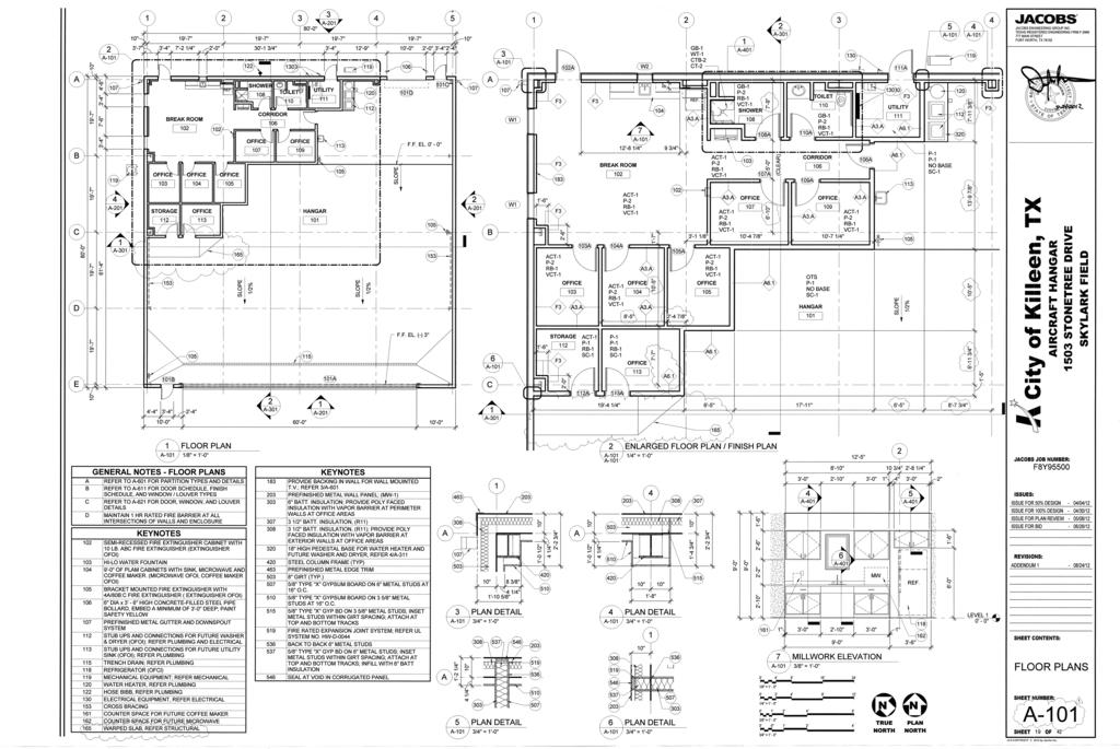
61