Biobehavioral Health Building
|
|
|
- Cornelius Bailey
- 5 years ago
- Views:
Transcription


1 Biobehavioral Health Building The Pennsylvania State University Daniel Bodde Structural Option Advisor Heather Sustersic
 Approximately 93,500 sqft Cost: $40")
2 Location: The Pennsylvania State University University Park, PA Project Size: 5 Stories above grade Full basement (100% below ground) Approximately 93,500 sqft Cost: $40 Million
3 Typical Section Foundation System: Spread footing Sits on bedrock (15 ksi)
4 Typical Section Foundation System: Spread footing Sits on bedrock (15 ksi) Superstructure: Concrete and composite metal deck

5 Lateral Layout Foundation System: Spread footing Sits on bedrock (15 ksi) Superstructure: Concrete and composite metal deck Lateral System: Steel Moment Frames Eccentric Braced Frame (Column Line 10)
6 Eccentric Braced Frame Foundation System: Spread footing Sits on bedrock (15 ksi) Superstructure: Concrete and composite metal deck Lateral System: Steel Moment Frames Eccentric Braced Frame (Column Line 10)

7 Statement: Steel has become an unviable option as main structural material Solution: - Redesign the structure using reinforced concrete with minimal impact on existing interior architecture and spaces One-way slab with interior beam Concrete moment frame

8 Statement: Steel has become an unviable option as main structural material Solution: - Redesign the structure using reinforced concrete with minimal impact on existing interior architecture and spaces One-way slab with interior beam Concrete moment frame Change façade to precast
9 Statement: Steel has become an unviable option as main structural material Solution: - Redesign the structure using reinforced concrete with minimal impact on existing interior architecture and spaces One-way slab with interior beam Concrete moment frame Change façade to precast Determine what impact the concrete redesign and precast façade have on the construction schedule
 Live Lobbies/Assembly (100 psf) Typical floor")
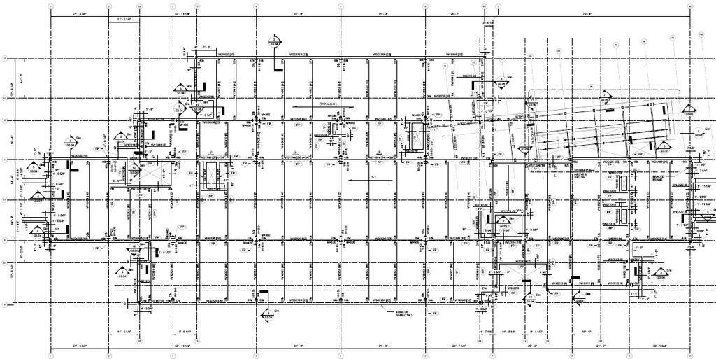
10 - Loads Gravity Loads: Dead Structure Self weight Superimposed (5 psf) Slate Floor (20 psf) Live Lobbies/Assembly (100 psf) Typical floor layout
11 - Loads Gravity Loads: Dead Structure Self weight Superimposed (5 psf) Slate Floor (20 psf) Live Lobbies/Assembly (100 psf) Lateral Loads: Wind (Controls) Seismic
12 - Gravity
13 - Gravity One-way Concrete Slab: 5 Slab (Table 9.5a) 12 oc (flexure) 10 (crack control)
14 - Gravity One-way Concrete Slab: 5 Slab (Table 9.5a) 12 oc (flexure) 10 (crack control) Beams : Support slab Run N-S Supported by girders, edge beams, & Columns Flexure & shear controlled design #5 in corners for cage construction Consistent concrete cross section
15 - Gravity One-way Concrete Slab: 5 Slab (Table 9.5a) 12 oc (flexure) 10 (crack control) Beams : Support slab Run N-S Supported by girders, edge beams, & Columns #5 in corners for cage construction Consistent concrete cross section
16 - Gravity Girders: Run E-W Supported by columns at both ends Concentrated loads produce large moments 2 shallower than existing steel structure Assumed 50% sustained live load for deflections
17 - Gravity Girders: Run E-W Supported by columns at both ends Concentrated loads produce large moments 2 shallower than existing steel structure Assumed 50% sustained live load for deflections
18 - Gravity Girders: Run E-W Supported by columns at both ends Concentrated loads produce large moments 2 shallower than existing steel structure Assumed 50% sustained live load for deflections Girder Deflections Actual Allowable Pass? i(d+l) 0.11 in L/ in Yes i(live) 0.06 in L/ in Yes long 0.2 in L/ in Yes
19 - Gravity Girders: Run E-W Supported by columns at both ends Concentrated loads produce large moments 2 shallower than existing steel structure Assumed 50% sustained live load for deflections Edge Beam: Run perimeter of BBH Building Concentrated load produces torsion Added longitudinal & transverse reinforcement Supports masonry
20 - Gravity Girders: Run E-W Supported by columns at both ends Concentrated loads produce large moments 2 shallower than existing steel structure Assumed 50% sustained live load for deflections Edge Beam: Run perimeter of BBH Building Concentrated load produces torsion Added longitudinal & transverse reinforcement Supports masonry
21 - Gravity Girders: Run E-W Supported by columns at both ends Concentrated loads produce large moments 2 shallower than existing steel structure Assumed 50% sustained live load for deflections Edge Beam: Run perimeter of BBH Building Concentrated load produces torsion Added longitudinal & transverse reinforcement Supports masonry Edge Beam Deflections Computed Allowable Pass? i(d+l) 0.29 in L/ in Yes i(live) 0.06 in L/ in Yes long 0.58 in L/ in Yes
22 - Lateral Concrete Moment Frame: Does not affect interior architecture. Stiff beam to column connection
23 - Lateral Concrete Moment Frame: Does not affect interior architecture. Stiff beam to column connection Wind Loads: Case 1 & Case 2 Controlled
24 - Lateral Concrete Moment Frame: Does not affect interior architecture. Stiff beam to column connection Wind Loads: Case 1 & Case 2 Controlled Relative Stiffness: 1 kip load applied to each frame Calculated relative stiffness based on deflection. Distribution of wind loads Frame K (k/in) K NS (k/in) K EW (k/in) Direct shear (kip) d (in) Kd^2 Kd^2 Torsional Moment Shear (kip) B C Total shear (kip) D E

25 - Lateral Concrete Moment Frame: Does not affect interior architecture. Stiff beam to column connection Wind Loads: Case 1 & Case 2 Controlled Relative Stiffness: 1 kip load applied to each frame Calculated relative stiffness based on deflection. Distribution of wind loads ETABS: Line elements with proper material & section properties Columns 0.70*Ig Beams 0.35*Ig Verified output with hand calculations

26 - Lateral Column Design: Corner, Interior, & Exterior Resists axial & flexural loads
27 - Lateral Column Design: Corner, Interior, & Exterior Resists axial & flexural loads Design Checks: Lateral Displacement < H/ D+L+W Displacement - X Direction Story Height Story Height Displacement H/400 Pass? (ft) (ft) (in) (in) Yes PH Yes Yes Yes Yes Displacement - Y Direction Story Height Story Height Displacement H/400 Pass? (ft) (ft) (in) (in) Yes PH Yes Yes Yes Yes
28 Cost Impact Steel Concrete Structural steel $297,025 Beams $220,000 Metal Deck $49,345 Columns $94,504 1" Spray on Fireproofing $12,968 Slab $141,000 Concrete fill $48,183 Total $455,504 Total $407,521 % increase 12% Cost Diff $47,984

29 Existing Façade: Traditional hand placed brick & limestone Held back by 8 fully grouted CMU Flashing, weep holes, & air barrier Heavy & Expensive


30 Existing Façade: Traditional hand placed brick & limestone Held back by 8 fully grouted CMU Flashing, weep holes, & air barrier Heavy & Expensive Alternative Façade: Thin brick precast panels Made in controlled conditions Faster Construction

31 Thin Brick Precast: Typical Layout Hung from edge beams Kickback provide lateral support
32 Thin Brick Precast: Typical Layout Hung from edge beams Kickback provide lateral support Thermal & Moisture Resistance: Sandwich Wall Provides rain barrier & thermal resistance Existing Wall Precast Wall Material Thickness (in) R-Value Material Thickness (in) R-Value Brick Thin Brick Air Cavity Sandwich Panel Walls Rigid Insulation Air Cavity Wall Insulation Between Fully Grouted CMU Studs(Total R=13) Air Cavity GWB GWB Total Resistance Total Resistance 9.5
33 Cost Impact: Traditional Masonry Brick $156,142 Brick $336,938 CMU $86,289 Cornice $81,250 Cleaning & Repointing $57,526 Total $418,188 Grouting $152,185 Reinf $8,000 Scaffolding $12,500 Total $472,642 % decrease 40% Cost Diff $54,454 Precast Panels
34 Construction Sequencing: Sequence 1: Col Line 1-5 Sequence 2: Col Line 5-10

35 Construction Sequencing: Sequence 1: Col Line 1-5 Sequence 2: Col Line 5-10 Assumptions: Reinforcement starts 1-3 days after forming starts Wait 7 days for concrete cure before construction on next floor
 Alternative precast façade: Mar.")
36 Construction Sequencing: Sequence 1: Col Line 1-5 Sequence 2: Col Line 5-10 Assumptions: Reinforcement starts 1-3 days after forming starts Wait 7 days for concrete cure before construction on next floor Key Completion Dates: Concrete redesign: Feb 3, 2012 (+3 months) Alternative precast façade: Mar. 15, 2012 (-6 months)
37 ; Successful concrete redesign Met all serviceability requirements Minimal impact interior architecture & layout
38 ; Successful concrete redesign Met all serviceability requirements Minimal impact interior architecture & layout : Matched existing thermal & moisture protection Cheaper Fast Construction
39 ; Successful concrete redesign Met all serviceability requirements Minimal impact interior architecture & layout : Matched existing thermal & moisture protection Cheaper Fast Construction : Develop an adjusted schedule Structure: + 3 months Façade: -6 months
40 Acknowledgments Massaro CM Services: Tim Jones Jim Kephart Keith Smith Robert Silman Associates: Dipa Makim The Entire Penn State Faculty Family & Friends
41
42 Snow Load Type Uniform (psf) Flat Roof Load 21 Sloped Roof Load 24 Lvl 2 Area DL Weight Slab superimposed Steel Façade CMU Int Brick Stone Floor Appendix Lvl 2 Area DL Weight Slab superimposed Steel Façade Int Brick Total ,032,837 Total ,159,042 Lvl 3 Area DL Weight Slab superimposed Steel Façade CMU Int Brick Stone Floor ,131,560 Lvl 4 Area DL Weight Slab superimposed Steel Façade CMU Int Brick Stone Floor Weight Comparison Lvl 3 Area DL Weight Slab superimposed Steel Façade CMU Int Brick Stone Floor ,043,033 Lvl 4 Area DL Weight Slab superimposed Steel Façade CMU Int Brick Stone Floor ,196,082 2,090,750 PH Area DL Weight Slab Roof Deck superimposed Steel Façade CMU Green Roof Roof Area DL Weight 1,668,010 PH Area DL Weight Slab Roof Deck superimposed Steel Façade CMU Green Roof ,739,750 Slate steel superimposed ,200 Roof Area DL Weight conc slab Slate steel superimposed Bld weight (lbs) 8,300, ,525 Bld weight (lbs) 8,472,895
 0 Frame W1: Case 1 NS K (k/in) PH Level K NS (k/in) K EW (k/in) Direct shear (kip) d (in) Kd^2 Kd^2 Torsional Moment Shear (kip) B 0.5502 0.00 4.23 0.00 32.50 581.15 17444.38 1.04 1.")

43 Appendix N-S ft E-W ft ft CR= 34 CR= By= 36 CM= 32 CM= Bx= 13 CR-CP= 2.00 CR-CP= F NS (kip) e NS (ft) 9 F EW (kip) 0 e EW (ft) 0 M NS (k-ft) M EW (k-ft) 0 Frame W1: Case 1 NS K (k/in) PH Level K NS (k/in) K EW (k/in) Direct shear (kip) d (in) Kd^2 Kd^2 Torsional Moment Shear (kip) B C Total shear (kip) D E Case 2 NS +.15By.75F NS (kip) e NS (ft) 45.75F EW (kip) 0 e EW (ft) 0 M NS (k-ft) M EW (k-ft) 0 Frame K (k/in) K NS (k/in) K EW (k/in) Direct shear (kip) d (ft) Kd^2 Kd^2 Torsional Moment Shear (kip) Total shear (kip) B C D E


44 Appendix Per floor Structure 1 to 5 5 to 10 Unit Daily Output Days Column Reinforment TONS Starts 7 days after beam and slab pour Column Forming SF Starts 1 day after Column Reinf Pour Columns CY Beam Forming SF use 2 crews Beam and Slab form starts 2 days after column form Beam Reinf TONS beam reif starts 4 days befor beam and slab form ends Slab Forming SF use 2 crews Slab Reinf TONS Pour Slab and Beams CY total per Precast Panels SF 3000 sequence
45