No-Dig Technology is the art and science of pipes, ducts and cables using techniques that minimizes / eliminates the need for excavation, i.e.
|
|
|
- Blake Martin
- 5 years ago
- Views:
Transcription
1 No Dig Technology
2 Introduction: No-Dig Technology is the art and science of installing, repairing or renewing underground pipes, ducts and cables using techniques that minimizes / eliminates the need for excavation, i.e., constructing ti under the surface or subsurface construction. The term trenchless technology has beeninuse on a global basis since the mid-1970s (Japan). The use of such techniques can reduce environmental impact, social costs and at the same time provide economic alternatives to traditional open cut methods of installation, renewal or repair.
3 No Dig Technology why adopt? Faster schedules can be achieved since time required for diversion of utilities, traffic etc are avoided. Works for installation of sewer pipes can carry on regardless of state of traffic at the ground level. Less relocation of utilities is required and risk of damage to utilities is reduced. Risk of damage to existing structures is reduced as pavements, roads, trees do not have to be excavated or cut. Surface settlement is minimized resulting in less damage to surrounding buildings and structures. No lowering of groundwater table is required. Existing commercial activities at ground surface can carry on unabated. Amount of earth moved is reduced, leading to lower disposal costs. Reduced risks to workers due to absence of temporary structures and earth collapse.
4 Types of Pipes: All types of rigid or flexible pipes can be burst/ installed/ repaired,viz: i Clay Steel Polymer Ductile Iron Polyethylene Cement Concrete Hobas (Fibre glass) Poly Vinyl Chloride (PVC) High Density Polyethylene (HDPE) Application: Gas Lines, Water Lines, Sewer Mains, Communication Ducts/Cables
5 Investigations: Site investigation to determine soil and groundwater conditions Inspection to determine the condition of the pipeline Location survey to determine the position of existing iti pipelines, other services and potential ti obstacles No-Dig Technology is concerned largely with services too small to permit man entry, generally up to about 900mm diameter pipes and ducts.

6 Site Investigation: For providing service it is important that adequate and detailed d site investigationi i with ihrelevant material iltesting be carried out and that the information and its interpretations are made available.
7 Condition Survey: This survey is carried out when there is doubt concerning the condition i of an existing i underground d network. It is important to carry out a CCTV survey.

8 Underground Detection: In No-Dig method the position of the driving tool is continuously monitored using a transmitter in the driving head and a locater on the surface.
9 No-Dig Systems: Trenchless Technology Systems for underground utility services fall into three broad categories: Installation of a new pipeline or duct; On line replacement of an existing pipeline or duct; Renovation/Repair i of an existing i pipeline or duct.
10 New Installations: The methods for the installation of a new pipeline or duct along with service connections are: Micro Tunneling Short Drive Systems Horizontal Directional Drilling Guided Drilling
11 Micro Tunneling Controlled Excavation Steerable - less than 1000mm diameter MTBM s have now been developed to work from drive shafts in almost all types of ground conditions. Micro tunneling is used extensively for sewerage work where surface disruption has to be minimized. It provides the necessary degree of accuracy in gravity lines. With the development of micro tunneling, both concrete and clay pipes have been designed with jacking in mind. Pipes in all conventional materials are produced with inwall joints and in shorter lengths to enable smaller drive shafts to be used, thus reducing excavation volumes and road occupancy.

12 Micro Tunneling Schematics courtesy of ISTT
13 Short Drive Systems Essentially Un Steered - Soil Displacement Auger Boring & Thrust Boring Auger Boring utilizes a rotating head to excavate the soil which is transported by auger flights operating in a casing to the drive pit. The head is recovered at an exit pit or in the trench cut for the adjacent length of pipeline. Auger boring is used in the range of mm diameter.
14 Short Drive Systems Impact Moling Impact moling is a technique in which a percussive mole (soil displacement hammer) is launched from an excavation to displace the soil and form a bore. The new conduit is normally drawn in behind themoleor pulled backintothe bore using the hammers reverse action. Pneumatically driven moles, in which the soil is displaced by the action of a percussive piston, have been developed in the range mm diameter for a single operation, with repetitive multiple passes to achieve mm diameter. They are used to install services for all utilities. Moles are commonly used by gas and water undertakings for installations of up to 40m under roads, drives and gardens in making 45-65mm diameter house connections.

15 Short Drive Systems Pipe Ramming/ Thrust Boring Are processes where a casing, usually steel, is driven through the ground from the drive pit to the exit pit. In Pipe Ramming, the casing is driven by a pneumatic hammer whilst in Thrust Boring it isadvanced dby astraight ihhydraulic push. Rams of pipes up to and over 2m diameter and exceeding 70m in length have been achieved.
16 Horizontal Directional Drilling Steerable Heavy, powerful rig - large size range - Long distances This system was originally i developed d by the oil industry for river crossings of small diameter where no high degree of accuracy was required. They are now widely used for installing pressure pipes under major obstacles such as motorway intersections, large rivers and airport runways.
17 Guided Drilling Steerable Small Rig - Shallow Drilling - Medium Length Guided drilling employs an excavation with compact light weight rig for rapid mobilization. Small diameter jets, mechanized cutting tools or displacement heads attached to a flexible drill string ti are positioned to form a bore as the head is thrust forward. The drilling head is launched from the surface at an inclined angle. Steering, inboth vertical and horizontal planes, is effected by controlling the orientation of a slant face at the head.
18 On-Line Replacement: Methods of on-line replacement are: Pipe bursting Pipe bursting Pipe Eating
19 Pipe Bursting New for Old without Trenching - Size for Size & Upsize Capable In this method old pipes are replaced by fragmenting the pipe of equal or larger diameter pipe. Pipe Bursting, sometimes called Pipe Splitting (used on non-fragmental pipes such as Steel, Ductile Iron or Polyethylene), l and has been developed d to exploit this resource. Initially the aim was for size-for-size replacement by splitting the defective pipe and displacing i the fragments to enable anewpipeline of the same diameter, usually of polyethylene (PE), to be drawn in.
20 Pipe Bursting It is used for replacement of fractured pipe usually from excavations m apart. Upsizing from 100mm to 225mm diameter is now well established, tblihdand pipes of up to 600mm diameter and greater have been replaced.
21 Pipe Bursting Two methods are commonly used as outlined: Static Bursting (Rod or Winch Systems) & Pneumatic Bursting

22 Pipe Eating New for Old without Trenching - Enlargement - Steerable Pipe Eating is an on-line micro tunneled replacement technique. The existing defective pipeline is crushed and removed through the new pipeline by the circulating slurry system. A new pipe is simultaneously installed by jacking bhidth behind themicro tunneling machine.
23 Renovation Renovation methods are: Slip lining Lining Formed in Place Spray-On Lining i Localized Repair Chemical Stabilization
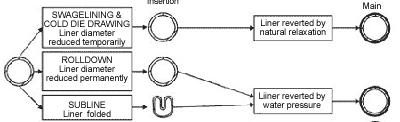
24 Sliplining New for Old without Trenching - Long Lengths It is one of the earliest forms of continuous structural lining. Anewpipeline pp of smaller diameter is inserted into the defective pipe and the annulus grouted. It is simple and is relatively inexpensive. However, there can be significant loss of hydraulic capacity. Examples include the pulling in of long lengths of PE pipes within water mains or the insertion of individual pipes within sewers. This is generally a low cost technique, which has the disadvantage of reduction of bore.
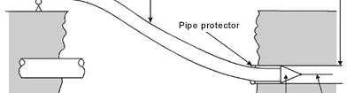

25 Sliplining
, which h is sprayed onto the surface of a cleaned main.")

26 Epoxy Spraylining System / CIPP These are methods of lining pipes with a thin lining of resin (typically 1mm thick), which h is sprayed onto the surface of a cleaned main. The aim of these techniques is to isolate the host pipe pp from the conveyed medium. There may be some potential for these techniques to be used to reinforce the structural capabilities of the host main.


27 Spray On Lining Corrosion Protection This is a well tried and tested technique for applying either anti-corrosion or structural lining to pipes. A high speed rotating head is winched through the pipeline, centrifugally depositing the lining material over the full internal surface.
28 Localised Repair Resin Injection and Chemical Grouting at Trouble Spots Local defects may be found in an otherwise sound pipeline, due to cracking or joint failure. Systems are available for remote control resin injection to seal localized defects in the range 100mm - 600mm diameter. Chemical Grouting with urethane and similar materials has been used for many years in sewer rehabilitation. Remote and man-entry grouting of defective joints and cracks may prevent infiltration and the formation of external voids in an otherwise sound pipeline.


29 Chemical Stabilization Restoring Support for Sewers The stability of sewers in doubtful ground conditions may be restored by treating manhole lengths with a two-part chemical dosing. The sewer length is sealed and filled first with solution A which h is then pumped out and refilled with ihsolution B which h is also subsequently pumped out. The chemical reaction between the components seals joints and cracks in the pipe and stabilises the surrounding soil.