Wavin AS Acoustic Soil System
|
|
|
- Cecil Christian Poole
- 5 years ago
- Views:
Transcription

1 Waste water drainage PRODUCT AND INSTALLATION MANUAL Uniclass EPIC L73131:P7110 J344:X721 CI/SfB (52.3) (In6) October 2015 SW216 Acoustic Soil System

2 Contents Introduction 2 Sound Insulation 3 Design and Installation 4 8 Wall Installation 4 Rainwater Down Pipes 4 How to Chamfer Pipe 4 Compensator Socket 5 Socket Connection 6 Connection to Pre-installed Pipe 6 Sound Insulation 6 Bracket Fixing Instructions 6 Bracket Arrangement 7 Fire Protection 8 Acoustic Soil Range 9 16 Transport, Handling and Storage 17 Handling, Storage and Safety 17 Technical Data 18 General Information technical.design@wavin.co.uk Acoustic Soil PIM 1


3 Introduction Acoustic Soil System is an effective low noise system, available in 110mm and 160mm. Complemented by a full range of push-fit fittings, the system offers flexibility of an extensive choice, excellent quality and reliability. Compared to cast iron, is quick and easy to install, because of its socket connections. is resistant to hot water and fulfils the mechanical test requirements of BS EN 1451, which means 95 C short term and 90 C long term temperature loading. Where PVC-U fittings are used, long term temperature resistance is reduced and only suitable for use with intermittent discharges of water up to 90 C. can be used for the drainage of waste water between ph 2 and ph 12. Features and Benefits High Density Material is made of a minerally reinforced polypropylene called Astolan. Because of its high specific weight and its special molecular structure, Astolan is able to absorb airborne sound as well as structure borne sound Easy Installation quick and economic in comparison to cast iron. is lightweight thus easy to handle. Installation is quick and easy, due to the proven push fit socket connections and easy pipe cutting, leading to time and cost savings Easy Fixing can be fixed with rubber lined metal brackets. Expensive fixing techniques are not necessary Durable is extremely robust, resistant to corrosion, internally very smooth and resistant to deposits Applications Multiple storey buildings requiring noise insulation: Hotels Hospitals Shopping malls Office buildings Residential homes High-rise apartments Schools and universities The system can be installed as: Soil stacks Internal rainwater systems Suspended pipe systems To allow waste connections to the main stack, can be used in conjunction with Wavin s standard waste systems. It can also be used in conjunction with standard PVC-U soil fittings if required. 2 Acoustic Soil PIM Customer Services: Technical Advice:

4 Sound Insulation General Principles With its excellent noise insulating characteristics, is the optimal solution where noise insulation is required. The patented raw material Astolan, a mineral filled polypropylene, has a high specific weight and special molecular structure, which enables absorption of a number of different sound sources. Structure Borne Sound Structure borne sound transmits from the shock or impact zone over the whole pipe. The special molecular structure of enables the absorption of structure borne sound. Airborne Sound Sound which diffuses in the air. Occurs inside the pipe due to impact and flow noises. Due to vibration of the pipe additional airborne sounds are generated. Sound energy is absorbed in the pipe wall. Impact Sound Sound which diffuses in solid materials. Structure borne sound is created by the impact of waste water on the pipe wall, especially in vertical stacks in the area of bends and branches. Sound Absorption The weight per meter of a soil and waste system is of great importance in absorbing airborne and structure borne sounds. The combination of high specific weight and high elasticity gives the optimal results in damping the transmission of both sounds through a pipe system. is specifically developed to make optimal use of both properties, the pipe weight of 110mm for example is no less than 3.55kg/m. This is heavy enough to provide appropriate sound absorption while still being significantly lighter than cast iron. pipe material provides excellent airborne sound absorbing behaviour, because of its high specific weight and special molecular structure. technical.design@wavin.co.uk Acoustic Soil PIM 3

 100 110 132 179 150 160 181 227 Rainwater Down Pipes Roof drainage pipes projected through living, sleeping and working rooms can be installed as pictured in Figure 1.")
5 Design and Installation Wall Installation Where is to be installed against a wall with separate decorative top layer (e.g. plaster boards), it is required that the brackets are fixed to the construction wall and not to the decorative layer. Pipe penetrations through the decorative layer can be mended by using elastic filler. Pipe Cutting can be cut simply with a commercial pipe cutter or handsaw. Always cut the pipe straight. Pipe and shaft dimensions to be taken from the table below and Figure 1. Table 1: Space Requirement for Pipes DN (mm) OD of pipe d a (mm) OD of socket d M (mm) Min. required spacing t erf (mm) Rainwater Down Pipes Roof drainage pipes projected through living, sleeping and working rooms can be installed as pictured in Figure 1. The specific area weight of the casing should be at least equal to the wall and preferably for both at least 220 kg/m2. When inserting pipe into the collar end of compensator socket Remove all swarf and burrs from the cut end and clean the pipe end. Bevel sharp cutting edge do not chamfer! Although the formation of condensation on the outside of Wavin AS pipes is less than on metallic pipes, it is recommended to insulate the pipes and fittings. Figure 1: Wall Installation Space Requirements Figure 2: Rainwater Downpipe Installation Inserting pipe into standard ringseal socket For connections to socketed pipe and other standard ringseal sockets, the ends of the pipe must be chamfered. How to Chamfer Pipe Casing 11.5cm brick and plaster Wall weight > 220 kg/m 2 Where chamfering is required for ringseal sockets only (not collar/ gasket end of compensator socket) use the special chamfering tool. Instructions are as follows: 1. Ensure pipe is held securely. 2. Remove end cap and load sponge with suitable lubricant. 3. Remove template from tool, snap onto pipe and slide to required length. Mark pipe and remove template. 4. Saw pipe to required length. 5. Ensure chamfering tool fits snugly into the pipe. 6. With torsion control dial on first setting (i.e one dot) turn handle in clockwise direction applying as little downward pressure as possible. Gradually increase torsion control until correct chamfer is achieved. 7. Remove tool from pipe. 8. Using lubricating sponge apply lubrication to end of pipe. 4 Acoustic Soil PIM Customer Services: Technical Advice:


6 Compensator Socket The compensator socket is a special fitting used to connect plain ended pipe to a branch so that: Maximum acoustic performance is achieved by preventing structure borne sound. Compensation is allowed for thermal movement on every floor without the need to employ the common practice of withdrawing pipe by 10mm from the fitting. This not only saves working time, but also gives additional technical security to the system. Fitting Instructions When making the connection with the compensator socket the following instructions should be adhered to: When installed vertically, please ensure that the collar/gasket end is facing down. Clean un-chamfered pipe end. Check the position and condition of the elastomeric sealing ring in the groove. Further check the condition of the elastomeric expansion collar. If necessary, clean fitting, sealing ring and collar. 1. Expansion collar Push the expansion collar over the pipe end. Please note: The expansion collar may only be pushed over the plain pipe ends, never over the spigot end of fittings. 2. Apply lubricant inside Apply lubricant inside compensator socket of fitting. Never use oil or grease. 3. Apply lubricant outside Apply and distribute Wavin lubricant evenly on outside of elastomeric compensator collar. Push fitting over compensator collar to full insertion depth. 4. Check final position Check final position of compensator collar. Ensure pipe end is flush with gasket tip. Depth of Insertion Indicators 5. Apply lubricant to spigot Apply Wavin lubricant on the spigot fitting and insert in the socket end to full depth. Gasket isolates pipe from fitting to prevent structure borne sound Allows thermal movement technical.design@wavin.co.uk Acoustic Soil PIM 5

7 Design and Installation Socket Connection For non-acoustic installations, the compensator socket is not essential, but an allowance for expansion using a standard socket is still required.the standard socket connection is to be installed as follows: Check position and condition of the elastomeric sealing ring in the groove. If necessary, clean fitting and sealing ring Clean and chamfer pipe end or spigot fitting Apply lubricant in a thin and equal layer on pipe end Insert pipe end straight to the central register of the socket Withdraw pipe by 10mm, never the fitting In the case of vertical soil stacks, the individual pipe lengths must be fixed immediately after assembly with pipe brackets, in order to avoid the pipe from sliding downwards and eliminating the 10mm expansion/ contraction allowance. (see Figure 3 and Bracket Fixing Instructions). Sound Insulation In order to achieve optimal sound insulation please consider the following: The pipe system must be free from the plaster layer, avoiding sound bridges. A layer of mineral wool or 5mm PE foam should be wrapped around the pipe, where contact with the structure of the building cannot be avoided (eg plaster layer or floor penetration). Emitted sounds depend highly on the course of the pipe. The prevention or reduction of impact zones leads to less sound emission. Therefore abrupt directional changes should be avoided. For optimal sound insulation, use full encircling brackets with rubber inserts. brackets are fitted with rubber inserts which insulates the system for structure borne sound. Figure 3: Thermal Expansion Method 10mm Connection to Pre-installed Pipe Using standard fittings, connections to pre-installed pipe can easily be achieved. Installation instructions using double socketed sleeves: 1. Cut out a sufficient length of pipe (length of fitting plus 2.5x OD of pipe). 2. Cut required pass length. 3. Deburr and bevel cutting edges. 4. Slide branch or access pipe on upper pipe end. 5. Fit one double socketed sleeve, over its full length, on pass length. 6. Fit one double socketed sleeve, over its full length, on lower pipe end. 7. Fit in pass length and close the pipe by sliding the double socketed sleeves in position. 8. Fix double socketed sleeves as pictured in Figure 4. Figure 4: Repair Sleeve Installation Double socketed sleeve Pass length Fixed bracket Min. 2.5 x OD Double socketed sleeve Fixed bracket Bracket Fixing Instructions Fixed Bracket The fixed bracket creates a fixed point in the pipe system. The pipe or fitting cannot be moved through the bracket after the screws are tightened (no longitudinal movement is possible). In order to prevent the vertical stack sliding down, each pipe section between floors must be secured by a fixed bracket. Also every horizontally installed pipe should always be fixed with one fixed bracket. All remaining pipe brackets (vertical and horizontal installation) must be sliding brackets. Prescribed bracket distances should not be exceeded. Use sound absorbing brackets, dimensionally compatible to the pipe diameter. Screw-pipe brackets with rubber inserts are recommended, which are fixed to the wall by screws and plastic plugs. Sliding Bracket By using sliding brackets the pipe can still be moved through the bracket after the screws are tightened (longitudinal movement is possible once installed). 6 Acoustic Soil PIM Customer Services: Technical Advice:
8 Bracket Arrangement During installation of pipes, the following should be considered: In case of horizontal installation, the pipe bracket spacing should be 10x the outside diameter of the pipe. In case of vertical pipe installation, depending on outside diameter, 1-2 metre Generally pipe brackets should not be installed in impact areas (eg diameter reductions and changes of directions in the system) Pipe brackets to be fixed to building materials with high specific area weight For stack pipes in open mounting shafts and high rooms (storey height over 2.5 meters) it is advised to use one fixed bracket and one sliding bracket per pipe length In buildings under 3 storeys (see Figure 5), the fixed bracket must be installed directly above the fitting at the bottom of the pipe end. The sliding bracket must be installed at a distance of maximum of 2 meters above the fixed bracket. This pattern should be repeated on the following floors In multiple storey buildings (from 3 storeys and more) the stack pipes of 110mm must be secured by additional fixing (stack pipe support) to prevent sliding. In this case we advise using the socketed short length with a fixed bracket (see Figure 5) Figure 5. Bracketing Arrangement Typical bracketing arrangement for under 3 storeys Typical bracketing arrangement for 3 storeys and over Compensator Socket 87.5 Branch Sliding Bracket* 2m Max 5mm PE foam wrap/mineral wool insulation Fire Collar Fixed Bracket** Compensator Socket Sliding Bracket* 87.5 Branch 2m Max 3.5m Max 5mm PE foam wrap/mineral wool insulation Fire Collar Compensator Socket Sliding Bracket* Fixed Bracket** Short Socket Length 87.5 Branch 5mm PE foam wrap/mineral wool insulation 2m Max Access Pipe 3.5m Max Fire Collar Compensator Socket Sliding Bracket* Compensator Socket Fixed Bracket** 87.5 Branch 2m Max Access Pipe (every 3rd floor) Compensator Socket Sliding Bracket* Fixed Bracket** Short Socket Length 87.5 Branch * Sliding brackets should be fitted with spacers, allowing the pipe to move through. 5mm PE foam wrap/mineral wool insulation ** Fixed brackets should be fitted tightly around the pipe, without spacers. Fixed Bracket** Sliding Brackets* Fixed Bracket** technical.design@wavin.co.uk Acoustic Soil PIM 7
 when tested to BS EN 1366-3:2004 for a fire resistance period of up to 120 minutes.")
9 Design and Installation Fire Protection Fire Collar System The Soil fire collar is for 110mm and 160mm pipes (when passing through steel framed partitions or masonry walls with a thickness of minimum 120mm and concrete floors with a thickness of at least 150mm) when tested to BS EN :2004 for a fire resistance period of up to 120 minutes. The fire collar has been approved by the Local Authority Building Control (LABC). The fire collar is designed to maintain the fire resistance of compartment walls and floors where they are penetrated by pipes. The depth of each seal is 60mm. The seals have a 1mm thick circular steel housing, powder coated, with fixing lugs at the base, spaced equidistant around the external periphery of the collar. Installation The fire stop seals are suitable to be installed through steel-framed partitions, masonry walls and concrete floors. The minimum permissible thickness of the masonry wall is 120mm and the minimum permissible thickness of the concrete floor is 150mm. Gaps around the pipes within the thickness of the wall or floor are sealed with a suitable fire rated intumescent mastic, backed by a plug of stone mineral wool or PE foam. The mastic should be about the same depth as the gap width. Use the intumescent mastic as shown around the fire collar to prevent structure borne sound. Figure 6. Fire Collar Installation Underside of Concrete Slab Pipe Each collar is fastened by means of a toggle clasp and has integral lugs at one end for ease of installation. 90 Branch Intumescent Acoustic Seal Beading The intumescent layers are held in position within the steel housing using tabs at the top of the collar, which are bent over. The depth of the tabs are proportional to the thickness of intumescent used. The total intumescent used is 8mm thick. The steel housing is produced from a single sheet of steel. The fire collar is suitable for use on PVC-U, MDPE, HDPE, ABS, PP and minerally reinforced polypropylene plastic pipes. See Figure 6 for positioning of fire collars. Screed Intumescent Acoustic Seal Pipe Screw (supplied) no rawlplugs required Coupler 25mm Mineral Wool or 5mm PE foam Fire Collar Table 2: Fire Collar Technical Detail Thickness of intumescent layer Number of intumescent layers Total thickness of intumescent Number of fixing lugs for masonry walls and concrete floors External pipe closure diameter Pipe OD 110mm 160mm 4mm 4mm 2 5 8mm 20mm mm 210mm 8 Acoustic Soil PIM Customer Services: Technical Advice:


10 Acoustic Soil Range Pipe Plain Ended Pipe Size (mm) Number d s L Single Socketed Pipe Size (mm) Number d d1 s t L Single Socketed 150mm Short Length Pipe Couplers Size (mm) Number Do1 Do2 Ds1 L L2.1 L Compensator Socket For acoustic performance and built in allowance for thermal expansion for more information see page 5 Size (mm) Number Do1 Do2 Ds1 L L2.1 L2.2 Z technical.design@wavin.co.uk Acoustic Soil PIM 9
 Number Do1 Ds1 L 110 3003343 132 110 117 160 3003345 188 160 143")
 Number Dn1 Do1 Ds1 L1.1 L2.")


11 Acoustic Soil Range Reducer Bends D/S Sleeve All push-fit sockets Size (mm) Number Do1 Ds1 L Single Socket Reducer One plain end and one push-fit ring-seal socket Size (mm) Number Dn1 Do1 Ds1 L1.1 L2.1 La Lb Z1 Z2 160/ S/S Bend 15 One plain end and one push-fit ring-seal socket Size (mm) Number Dn1 Do1 Ds1 L1.1 L2.1 Z1 Z S/S Bend 30 One plain end and one push-fit ring-seal socket Size (mm) Number Dn1 Do1 Ds1 L1.1 L2.1 Z1 Z Acoustic Soil PIM Customer Services: Technical Advice:

")
 Number 1 Z1 Z2 110 3020501 110 132 110 61 61")
 Number Dn1 Do1 Do2 Ds1")

12 S/S Bend 45 One plain end and one push-fit ring-seal socket Size (mm) Number Dn1 Do1 Ds1 L1.1 L2.1 Z1 Z º S/S Bend 67 One plain end and one push-fit ring-seal socket Size (mm) Number Z1 Z S/S Bend 87 One plain end and one push-fit ring-seal socket / PVC-U Size (mm) Number Dn1 Do1 Ds1 L1.1 L2.1 Z1 Z Branches S/S Equal Branch 45 One plain end and two push-fit ring-seal socket Size (mm) Number Dn1 Do1 Do2 Ds1 Ds2 L L1.1 L2.1 L2.2 Z1 Z2 Z technical.design@wavin.co.uk Acoustic Soil PIM 11
 Number Z1 Z2 Z3")


 Number Dn1 Do1 Ds1 L L1.1 L2.")

13 Acoustic Soil Range S/S Equal Branch 67 One plain end and two push-fit ring-seal socket Size (mm) Number Z1 Z2 Z S/S Equal Branch 87 One plain end and two push-fit ring-seal socket Size (mm) Number Z1 Z2 Z S/S Unequal Branch 45 One plain end and two push-fit ring-seal socket Size (mm) Number Dn1 Do1 Do2 Ds1 Ds2 L L1.1 L2.1 L2.2 Z1 Z2 Z3 110/ S/S Double Branch 87 One plain end and three push-fit ring-seal socket Size (mm) Number Z1 Z2 Z S/S Corner Branch 87 One plain end and three push-fit ring-seal sockets Square entry Size (mm) Number Dn1 Do1 Ds1 L L1.1 L2.1 Z1 Z2 Z Acoustic Soil PIM Customer Services: Technical Advice:
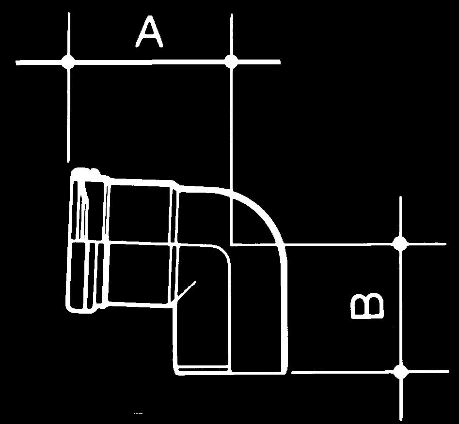
 Size (mm) Number Degree A B 110 3020490 Straight 180 132 110 LH 3020491 8º 180 16 132 110 LH 3020492")


14 D/S WC Manifold Branch Straight All push-fit sockets Material: PVC-U with EDPM seals Nominal Part Offset Dimensions (mm) Effective Length (mm) Size (mm) Number Degree A B Straight LH º LH º LH º LH LH RH º RH º RH º RH RH Access Pipe S/S Access Pipe Rectangular access One plain end and one push-fit socket Size (mm) Number Dn1 Do1 Ds1 K L L1.1 L2.1 Z Bossed Pipe Single Boss Pipe Spigot Tail One plain end and two push-fit ring-seal sockets Material: PVC-U, with EPDM seals Nominal Part Size (mm) Number 110x x x technical.design@wavin.co.uk Acoustic Soil PIM 13


 when")

 Number A B 50 2CS355 70 65 All-Fit 90º")

15 Acoustic Soil Range Manifold Soil Manifold One plain end and one push-fit ring-seal socket Permits up to three 50mm connections to be made at floor level Complies with BS EN :2000 clause ND Make connections using 2CS354 (below), 2C355 or 2C356 Minimum installation aperture: 240mm square Material: PVC-U, with Rubber seals Size (mm) Number A B C D All-Fit Reducer 40:32mm Connects to 32mm plastic pipe to BS EN /BS EN / BS EN , or to copper pipe manufactured to BS 659 or BS 2871 Use with 2CS355 (below) when a bend is required Material: Polypropylene Size (mm) Number A 40 2CS All-Fit Reduction Bend 50:40mm Connects to 40mm plastic pipe to BS EN /BS EN / BS EN , or to copper pipe manufactured to BS 659 or BS 2871 Material: Polypropylene Size (mm) Number A B 50 2CS All-Fit 90º Spigot Bend 50mm Connects to 50mm plastic pipe to BS EN /BS EN / BS EN , or to copper pipe manufactured to BS 659 or BS 2871 Material: ABS Size (mm) Number A B 50 2CS Acoustic Soil PIM Customer Services: Technical Advice:
")


16 Adaptor to Cast Iron Cast Iron Connector to Cast Iron Connects from to Cast Iron Stop End Material: Steel Nominal Part Size (mm) Number Socket Plug Size (mm) Number L Safety Clip for Socket Plug Fire Collar Material: Stainless Steel Nominal Part Size (mm) Number Fire Collar Fixing lugs for masonry walls and concrete floors Material: Steel, Intumenescent layer Nominal Part Size (mm) Number technical.design@wavin.co.uk Acoustic Soil PIM 15


 Nominal Part Size (mm) Number 110 3020512 M10 x")
 Size (mm) Number M10")
 Number 110 4006583 160 3000177 Spare Collar")

17 Acoustic Soil Range Accessories and Spares Pipe Bracket with Rubber Insert M10 Female thread for fixing Can be used both as a fixed and as a sliding bracket with spacer washer for location only without spacer washer for tight fixing Material: EPDM, Steel (Zinc Plated) Nominal Part Size (mm) Number Chamfering Tool For pipe chamfering Use for standard pipe/socket connections (not compensator socket gasket end) Nominal Part Size (mm) Number M10 x 80mm Bolt Fixing for Solid Wall Socket suitable for Torx screwdriver Material: Steel (Zinc Plated) Size (mm) Number M Spare Sealing Ring Material: Rubber Nominal Part Size (mm) Number Spare Collar Material: Rubber Nominal Part Size (mm) Number Acoustic Soil PIM Customer Services: Technical Advice:
18 Transport, Handling and Storage Handling, Storage and Safety Handling Care should be taken when handling pipe and fittings. Excessive scratching or scoring harms the appearance and can also affect the joint sealing. Take extra care when handling pipe and fittings in wintry conditions. Cold weather reduces the impact strength of plastics. Use nylon belt slings, or forklifts with smooth forks, for mechanical unloading of block bundles. Metal slings, hooks or chains must not come into contact with pipes (see Figure 1). Load and unload loose pipe by hand. Avoid using skids. When loose pipes have been transported one inside the other, always remove the inner pipe first. Figure 1: Unloading of block bundles Maximum stack size: 7 layers or 2m high (see Figure 2). Stack Socketed Pipe with sockets protruding and placed at alternate ends to ensure pipe is evenly supported. Fittings Store fittings supplied in plastic bags away from direct sunlight. If this is not possible, open bags to prevent a build-up of temperature. Fittings in cardboard packaging (e.g. Fire Stop Seals and Air Admittance Valves) should be stored under cover until required. Store degreasing cleaners, silicone lubricant, solvent cement and fillers in a cool place away from any heat source and out of direct sunlight. Safety The relevant regulations detailed in the Health and Safety at Work Act 1974 must be adhered to on site. Figure 2: Storage of loose pipe on the ground Storage 2m or 7 layers max. Always store pipe on a reasonably flat surface free from sharp projections. Block Bundles 2m Block bundles can be stored up to 3m high without extra side supports or bearers. Block bundles will remain free-standing when cut. Take care when releasing bundles as the straps are under considerable tension and may flail when cut. Figure 3: Storage of loose pipe on bearers Loose Pipes Loose pipe requires side supports at least every 2m. These supports should consist of battens at least 75mm wide. Ideally, support loose gutter or pipe uniformly throughout its entire length. If this is not possible, place timber supports at least 75mm wide at 1m maximum centres beneath the pipe (see Figure 3) Stack different size pipe separately, or, if not possible, stack with larger diameters at the bottom. 75mm bearing width 1m spacing maximum technical.design@wavin.co.uk Acoustic Soil PIM 17
19 Technical Data Material Astolan ; polypropylene, minerally reinforced, resistant to hot water, DIN 4102, B2. Table 3: Physical Characteristics of Astolan Physical Characteristics of Mineral Reinforced Astolan Density 1.9 g/cm 3 3 DIN Elongation at break 29% Tensile strength 13 N/mm 2 E-modulus 3800 N/mm 2 Coefficient of thermal linear expansion 0.09 mm/mk Fire resistancy DIN 4102, B2 Colour Light grey RAL 7035 Marking, nominal diameter, production year, quality mark, approval, material, control mark, fire classification. Example:, DN 100, 2002, Z , ASTOLAN, Ü DIN 4102, B2. Important Note Some fittings in the range are manufactured from PVC-U. These are: Soil Manifold l Bend 87º WC Manifold Branches l Single Boss Pipes Solvent cement should not be applied to pipe and fittings, as minerally reinforced polypropylene WILL NOT BOND TO PVC. PVC-C Waste can be connected via the the universal push-fit connection sockets on the Acoustic Soil fittings. 18 Acoustic Soil PIM Customer Services: Technical Advice:

20 General Information Quality, Standards and Approvals The British Standards Institution has issued certificates registering Wavin as a firm of assessed capability, with a quality management system which meets the requirements of BS EN ISO Wavin systems are the benchmark for excellence and product innovation: precision-manufactured using the most advanced injection moulding and extrusion machines. All products comply with or exceed relevant British and European standards to ensure reliability and long-lasting service. The System has been tested by the Local Authority Building Control (LABC), who are satisfied that where robust construction details are not to be followed, the use of the Wavin AS System (without a mineral wool wrap) and only a nominal plasterboard encasement should not compromise any acoustic testing of a penetrated floor. Certificate number , tested in accordance with BS EN The System also meets the acoustic requirements of the German standard DIN 4109, achieving a sound performance of under 30dB (A) at 2l/s. The System also has the following worldwide approvals: Fire Test and Assessment Reports Passed and certified to BS 476 part 20 and EN LANTAC Building Control Approval LABC Type Approval Environment All Wavin manufacturing sites operate Environmental Management Systems which comply with the requirements of and are certified to ISO 14001: Health and Safety The relevant provisions of the following legislation should be adhered to on site: Construction (Design and Management) Regulations 1994 Control of Substances Hazardous to Health Regulations 1988 Health and Safety at Work Act 1974 Management of Health and Safety at Work Regulations 1999 Manual Handling Operations Regulations 1992 Hazards Associated with PVC-U, PVC-C, Polypropylene and Polyethylene Approvals Worldwide UK LABC System Approval, Cert. No Tested in accordance with BS EN 1451 RAL quality mark of the Germany Germany Community of Plastic Pipes (GKR), Bonn German Institute of Building (DiBt) general building inspection approval Denmark ETA Denmark VA 2.14 DK 6858 Norway Godkjenningsnmnda vor Sanitärmateriell Nr Sweden Boverket DNR /90 Australia Watermark Nr.:MP52 Spec 005 Turkey Turkish Standards Quality Appropriateness Certificate Poland Aprobata techniczna COBRTI INSTAL Nr AT LABC System Type Approval Cert. No Tested in accordance with BS EN 1451 There are no particular hazards associated with handling, cutting or working with the materials mentioned above, and protective clothing or equipment is not normally required. Safety Data Sheets covering PVC-U, PVC-C, PP, PE, lubricant, solvent cements and cleaners are available from the Wavin Technical Design Department, please call Technical Enquiries to obtain a copy. Supply All systems are supplied through a nationwide network of merchant distributors. For details of your nearest merchant, contact Wavin Customer Services. Sealing Rings Where applicable, Sealing Rings are supplied fitted to each component and are included in the price. Conditions of Sale Wavin will not accept responsibility for the malfunction of any installation which includes components not supplied by Wavin. Goods are sold subject to Company conditions of sale. technical.design@wavin.co.uk Acoustic Soil PIM 19
21 General Information Other Wavin Industrial and Commercial Systems Tigris K1 Multilayer Press-fit System High efficiency supply system for potable water, sanitary and heating applications. Efficient installation, superlative performance Advanced performance Hot & Cold plumbing system designed for potable, sanitary and heating applications in industrial, commercial and other large buildings Fully-proven in Europe for over 10 years and now available for selection by specifiers and installers in the UK Certus PVC-U Compact Soil System With its compact 110mm and 160mm soil fittings, the Certus PVC-U Compact Soil System is particularly suitable for installation where space is at a premium With both solvent-weld and push-fit connections Branches available with rotating bases: enables connections in difficult-to-reach spaces Innovative stop position on fitting to prevent waste being installed with a fall less than 2.5º Manufactured to BS EN 1329:2001 / BS EN :2000 Certus PVC-C Waste System A solvent weld waste system designed for higher temperature in service usage 32mm, 40mm and 50mm sizes (OD) Heat resistant and fire retardant properties UV resistance allows exterior as well as interior installation Manufactured to BS EN :20000 Manufactured to BS EN 1329:2001 / BS EN : 2000 Technical Advice Acoustic Soil is backed by Wavin s comprehensive technical advice service. This is available to provide expert assistance at every stage of a project, from planning and product selection to installation and maintenance. Literature The following Wavin publications are also available from the Literature Department at Chippenham. General Wavin Above Ground Systems: Trade Price List Above Ground Systems Osma Soil and Waste: Product and Installation Manual Osma Rainwater: Product and Installation Manual Tigris K1: Product and Installation Manual Hep 2 O: Product Guide Wavin AG Commercial: Product Guide Wavin Certus Soil and Waste: Product Overview Wavin QuickStream Siphonic Roof Drainage: Product Overview To request details with regards to any of the above components and/or for any technical enquires please contact: Literature Request Tel: literature@wavin.co.uk Technical Design Tel: technical.design@wavin.co.uk Wavin Online The complete range of Wavin/Osma product and installation guides are also available online at: wavin.co.uk Contact Wavin Technical Design Department: Tel: technical.design@wavin.co.uk or via online enquiry at wavin.co.uk 20 Acoustic Soil PIM Customer Services: Technical Advice:


22 Discover our broad portfolio at Water management Plumbing and heating Waste water drainage Water and gas distribution Cable ducting Wavin Limited Registered Office Edlington Lane Doncaster DN12 1BY Tel Wavin Limited Wavin operates a programme of continuous product development, and therefore reserves the right to modify or amend the specification of their products without notice. All information in this publication is given in good faith, and believed to be correct at the time of going to press. However, no responsibility can be accepted for any errors, omissions or incorrect assumptions. Users should satisfy themselves that products are suitable for the purpose and application intended. For further product information visit: wavin.co.uk SW216 October 2015