MECHANICAL and OPTICAL ANALYSES FOR X-RAY MIRROR MODULES IN X-RAY SATELLITE MISSIONS
|
|
|
- Abner Hill
- 5 years ago
- Views:
Transcription
1 MECHANICAL and OPTICAL ANALYSES FOR X-RAY MIRROR MODULES IN X-RAY SATELLITE MISSIONS Giancarlo Parodi, BCV progetti S.r.l., Via Sant Orsola Milan Tel Fax giancarlo.parodi@bcv.it 1
2 Since 1984 BCV progetti S.r.l. has been involved in mechanical and optical analyses of Wolter I X-ray Mirror Modules [MM]. BCV has been responsible for MM mechanical and optical analyses in the following missions: Beppo-SAX JET-X XMM SWIFT Moreover during these last 20 years BCV supported Brera Observatory in developping new technologies for Mirror Shell [MS] production, MM design and integration for other project missions (WFXT, XEUS, Constellation X) 2
3 The main tasks carried out by BCV in these projects have been: MM design, mechanical analyses and structural optimisation in different environmental static and dynamic conditions. Analyses of MS shape errors during manufacturing, handling, integration, on ground testing and operative conditions and evaluations of the consequent optical degradation. Assistance for on ground mechanical tests. Design of equipment and tools for a safe MM integration and handling. Implementation of dedicated software. The main codes actually used in BCV for this sort of activities are: ANSYS for thermo-mechanical analyses. RATOS for ray tracing optical analyses. RATOS being a proprietary code realised directly by BCV. 3
4 THIN MIRROR SHELLS PRELIMINARY ANALYSES At the moment the MM more similar to Simbol-X configuration, between those ones analysed by BCV, is the Hard X ray telescope of Constellation-X Mission [Con-X/HXT]. SIMBOL-X Con-X/HXT Optical configuration Wolter I Wolter I MS material Ni Ni Focal length [mm] Max. diameter [mm] MM length [mm] MS thickness [mm] ~0.13 Preliminary analyses have been carried out for Con-X/HXT configuration dealing with: MM configuration - spider numbers MS integration procedure MS frequencies MM structure 4
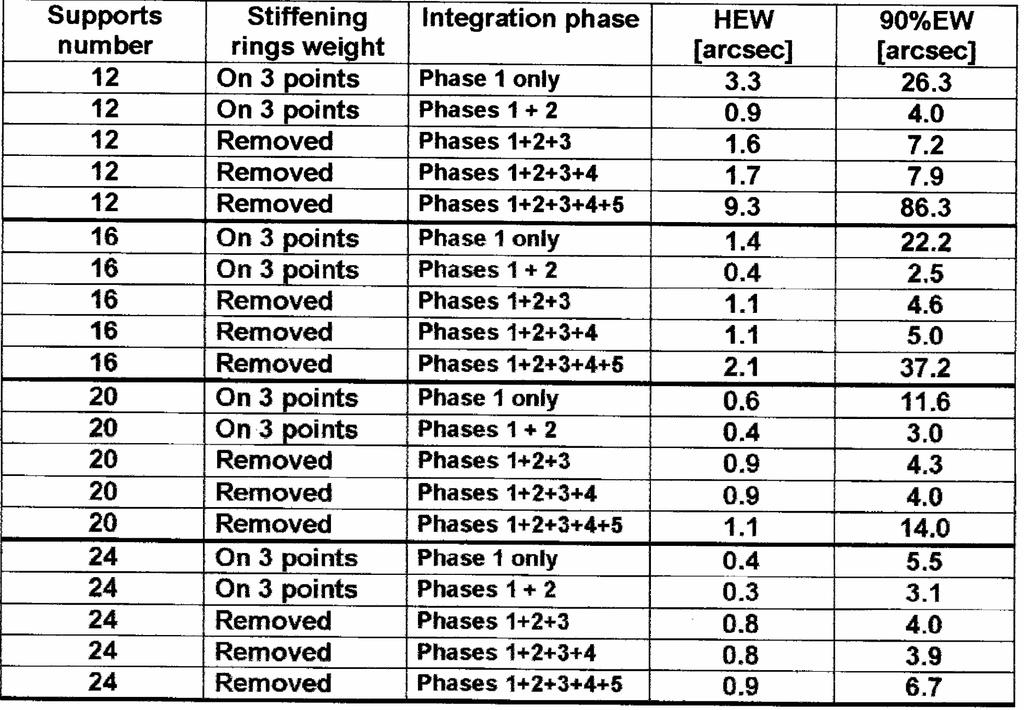
5 Con-X HXT - Integration procedure: 1) The MS, in vertical direction, rests on 12, 16, 20 or 24 astatic supports placed at the bottom end section ( MAX). Near the two end sections Al stiffening rings 2mm thick and 25mm wide are placed, in order to restore and to maintain the MS roundness. 2) The MS is connected (glued) at the 12, 16, 20 or 24 integration structure spokes at the exit section (upper section at MIN) and the astatic supports at MAX are removed. In this configuration the MS +Al rings hang from the upper glued connections. 3) The MS is connected at 12, 16, 20 or 24 integration structure spokes at the entrance section ( MAX) and the Al stiffening rings are removed (mass and stiffness). 4) The axial gravity is released. 5) Gravity in lateral direction is applied (testing condition). MM and spoke have been assumed as infinitely stiff. Different number of astatic supports and spiders have been compared. No glue shrinkage effect are taken into account 5
![Radial displacement isocontours [m] for MS 300mm diam. 0.13mm thick 12 supports/spiders Phase 1) Phase 2) Phase 4) Phase 5) PtoV = 7.3µm PtoV = 2.1µm PtoV = 0.](/docs-images/86/94404291/images/6-1.jpg "7µm PtoV = 28.6µm Radial displacement isocontours [m] for MS 300mm diam. 0.13mm thick 24 supports/spiders PtoV = 3.5µm PtoV = 2.0µm PtoV = 0.2µm PtoV = 3.")
6 Radial displacement isocontours [m] for MS 300mm diam. 0.13mm thick 12 supports/spiders Phase 1) Phase 2) Phase 4) Phase 5) PtoV = 7.3µm PtoV = 2.1µm PtoV = 0.7µm PtoV = 28.6µm Radial displacement isocontours [m] for MS 300mm diam. 0.13mm thick 24 supports/spiders PtoV = 3.5µm PtoV = 2.0µm PtoV = 0.2µm PtoV = 3.0µm 6
7 7
8 Con-X HXT - Astatic force tolerance We considered the effect of a random distribution of the axial force on the 12 astatic supports at MAX in the first phase of the integration procedure. The maximum force error has been assumed equal to the 10%. 8

9 Con-X HXT -?CTE between MM and MS material EFFECTS IN AXIAL DIRECTION Being the MS fixed at both end sections in case of differences in CTE between MM and MS materials an axial stretching-crushing of the MS will be produced. In the following table we summarise the results obtained by applying an axial stretching equal to 5 µm to the 12, 16, 20 or 24 spoke connections at the exit section ( MIN). The MS was already connected to the integration structure, both cases with and without stiffening rings have been considered. It has to be noted that a stretching equal to 5µm, uniform on the whole MS section, requires a resultant force approximately equal to 0.18 kn. 9


10 Con-X HXT -?CTE between MM and MS material radial displacement isocountours 12 spider 5µm axial stretching PtoV 25.6 µm HEW=45.5 arcsec 24 spider 5µm axial stretching PtoV 6.9 µm HEW=0.7 arcsec 10
 I Frequency 110 Hz 98 Hz II Frequency 115 Hz 99 Hz III Frequency 117 Hz 104 Hz R=145mm 0.12mm thick 24 spiders first modal shape at 110 Hz R=350mm 0.")
11 SIMBOL-X MS FREQUENCIES WITH RIGID CONNECTIONS (SPHERICAL HINGES) Rint 145mm 350 mm Focal 30 m 30 m MS thickness 0.12 mm 0.3 mm Support number 24 (both end sect.) 24 (both end sect.) I Frequency 110 Hz 98 Hz II Frequency 115 Hz 99 Hz III Frequency 117 Hz 104 Hz R=145mm 0.12mm thick 24 spiders first modal shape at 110 Hz R=350mm 0.30mm thick 24 spiders modal shape at 98 Hz 11


 ±0.07 µm ±0.16 µm Lateral gravity (radial displ.")
12 SIMBOL-X MS WITH RIGID CONNECTIONS (SPHERICAL HINGES) DEFLECTIONS DUE TO 1g GRAVITY Rint 145 mm 350 mm Focal 30 m 30 m MS thickness 0.12 mm 0.3 mm Support number 24 (both end sect.) 24 (both end sect.) Axial gravity (radial displ.) ±0.07 µm ±0.16 µm Lateral gravity (radial displ.) ±1.7µm ±4.3 µm (±3µm fixed connect.) 12
 Radial displ. PtoV 11.7 µm 20.4 µm HEW 1.2 arcsec 25.3 arcsec 90%EW 46.8 arcsec 121.0 arcsec Radial displ.")
13 SIMBOL-X +1 C UNIFORM ON SINGLE MS Rint 145 mm 350 mm Focal 30 m 30 m MS thickness 0.12 mm 0.3 mm Support number 24 (both end sect.) 24 (both end sect.) Radial displ. PtoV 11.7 µm 20.4 µm HEW 1.2 arcsec 25.3 arcsec 90%EW 46.8 arcsec arcsec Radial displ. Isocontours [m] Spot diagram Spot diagram 13
 Rint 145 mm")


14 SIMBOL-X +1 C -1 C THERMAL GRADIENT ALONG MS DIAMETER (MS FREE) Rint 145 mm 350 mm Focal 30 m 30 m MS thickness 0.12 mm 0.3 mm Radial displ. PtoV 4.2 µm 9.2 µm HEW 8.7 arcsec 3.7 arcsec 90%EW 18.5 arcsec 7.9 arcsec Applied temperature Applied temperature Radial displ. Isocontours [m] Spot diagram Spot diagram 14
 mass equal to 38 kg.")


15 CON-X HXT - Preliminary analyses of the Mirror Module Different preliminary configurations have been investigated, with the goal of reducing as much as possible its mass and with the constraints to respect some requisites in terms of stiffness and strength. DATA Ni Electroformed Mirror Shells (MS) mass equal to 38 kg. MS glued at front and rear section to spoke wheels having 20 spiders each. Total spoke wheels mass equal to 6.25 kg. MM constrained to the satellite bulkhead in three points, placed approximately at the intermediate section, 120 spaced along azimuth, and considered as spherical hinges in the following analyses. The MM case is directly connected to the satellite bulkhead at the three points mentioned above, without any adapter or spacer in between, in order to save mass. In the analyses the bulkhead has been considered infinitely stiff. MM case realised using proper stainless steel, having the Coefficient of Thermal Expansion (CTE) in good agreement with the electroformed Ni CTE. 15
 and consequent impact on MS #1 for 1g in axial or in lateral direction.")
16 Preliminary analyses of the Mirror Module The different preliminary configurations have been investigated respect to the following parameters: MM mass, MM stresses under 20g in any direction, MM buckling, MM frequencies, Axial displacements at the two end rings (interface with MS) and consequent impact on MS #1 for 1g in axial or in lateral direction. Configuration having cylindrical skin with circular lightening hole pattern gives the best performances. 16

17 CON-X HXT - Stress level due to uniform?t +?CTE or uniform CTE +?T between MS and MM We suppose that the MS CTE is K-1 greater than the structure CTE and an uniform temperature change T = +20 C equal no MS and structure occurs. The MM has been considered infinitely stiff. By knowing the stress-strain curve of the material and its microyielding limit it should be possible to carry out some non linear analyses (in case of low microyielding), to check the optical impact due to stresses caused by uniform?t +?CTE or uniform CTE +?T between MS and MM. 17