This is a repository copy of Cross-sectional optimization of cold-formed steel channels to Eurocode 3.
|
|
|
- Ruth O’Neal’
- 5 years ago
- Views:
Transcription
 (2015) Cross-sectional optimization of cold-formed steel channels to Eurocode 3.")

1 This is a repository copy of Cross-sectional optimization of cold-formed steel channels to Eurocode 3. White Rose Research Online URL for this paper: Version: Accepted Version Article: Ma, W., Becque, J., Hajirasouliha, I. et al. (1 more author) (2015) Cross-sectional optimization of cold-formed steel channels to Eurocode 3. Engineering Structures, ISSN Reuse Unless indicated otherwise, fulltext items are protected by copyright with all rights reserved. The copyright exception in section 29 of the Copyright, Designs and Patents Act 1988 allows the making of a single copy solely for the purpose of non-commercial research or private study within the limits of fair dealing. The publisher or other rights-holder may allow further reproduction and re-use of this version - refer to the White Rose Research Online record for this item. Where records identify the publisher as the copyright holder, users can verify any specific terms of use on the publisher s website. Takedown If you consider content in White Rose Research Online to be in breach of UK law, please notify us by ing eprints@whiterose.ac.uk including the URL of the record and the reason for the withdrawal request. eprints@whiterose.ac.uk
2 MA W, BECQUE J, HAJIRASOULIHA I & YE J (2015) CROSS-SECTIONAL OPTIMIZATION OF COLD- FORMED STEEL CHANNELS TO EUROCODE 3. ENGINEERING STRUCTURES, 101, Cross-sectional optimization of cold-formed steel channels to Eurocode 3 Weixin Ma, Jurgen Becque, Iman Hajirasouliha and Jun Ye* Department of Civil and Structural Engineering, The University of Sheffield, Sheffield, UK Abstract Corresponding author s zjuyejun@gmail.com Cold-formed steel structural systems are widely used in modern construction. However, identifying optimal cross section geometries for cold-formed steel elements is a complex problem, since the strength of these members is controlled by combinations of local, distortional, and global buckling. This paper presents a procedure to obtain optimized steel channel cross-sections for use in compression or bending. A simple lipped C-shape is taken as a starting point, but the optimization process allows for the addition of double-fold (return) lips, inclined lips and triangular web stiffeners. The cross-sections are optimized with respect to their structural capacity, determined according to the relevant Eurocode (EN ), using genetic algorithms. All plate slenderness limit values and all limits on the relative dimensions of the cross-sectional components, set by the Eurocode, are thereby taken into account as constraints on the optimization problem. The optimization for compression is carried out for different column lengths and includes the effects of the shift of the effective centroid induced by local buckling. Detailed finite element models are used to confirm the relative gains in capacity obtained through the optimization process. Key words: Cold-formed steel; Optimization; Buckling modes; Compressive strength; Bending strength; Finite element modelling 1
3 1. Background Cold-formed steel structural members are produced by bending relatively thin metal sheets into a variety of cross-sectional shapes by either a cold-rolling or a press braking procedure. They have a multitude of applications which are traditionally centered around their use as secondary load-bearing elements in buildings e.g. as roof purlins, wall girts or stud walls. However, over the past decades there has been a widening in the range of applications for cold-formed steel beyond these traditional areas. A good example is the emergence of specialized and standardized cold-formed steel framing systems which allow low- to mid-rise buildings to be constructed entirely out of cold-formed steel. Another example is the use of cold-formed steel in portal frames for industrial halls. In both cases, cold-formed steel members are used as the primary load-bearing members and consequently have to meet increased demands in terms of load-carrying capacity and span lengths. Trapezoidal steel decking, extensively used in composite construction and also subject to a trend towards larger span lengths, also forms an important application of cold-formed steel, as are wall and roof cladding and steel storage racks. Cold-formed steel structural members offer a wide range of advantages. They typically exhibit a high strength-to-weight ratio, indicating an efficient use of the material and lending them tangible sustainability credentials (in addition to being fully recyclable). They are lightweight and, as a result, easy to handle, stack, transport and install. They are produced at room temperature and can easily be formed into a variety of shapes. Advances in manufacturing techniques have thereby resulted in new, complex cross-sectional shapes to appear on the market which feature rolled-in intermediate stiffeners, return lips, corrugations, web openings, embossments and innovative geometries. A few examples of commercially available cross-sections are shown in Fig. 1. This versatility in the 2
4 manufacturing process offers great scope and potential to develop cross-sections which are highly optimized for their specific applications. Because of their limited wall thickness, however, cold-formed steel structural members are typically susceptible to a number of instabilities which are not as commonly encountered in hot-rolled steel members. These instabilities are usually categorized into local, distortional and global buckling modes, as illustrated in Fig. 2, but may also appear simultaneously and interact with each other to affect the structural capacity in a detrimental way. The complexity of stability issues in cold-formed steel members, combined with the potential intricacy of cross-sectional geometries make the design of cold-formed steel members a challenging exercise which requires a high level of expertise. Over past decades significant progress has been made in understanding the structural behaviour of cold-formed steel structures and much of the research effort has culminated in the advancement of coldformed steel design standards around the world for the benefit of designers. In particular, EN [1] reflects many decades of research and its design guidelines and provisions were used to develop the research presented in this paper. In what follows, a framework is first developed which can be used to optimize the parametrized cross-sectional shape of a cold-formed steel structural member. It adopts the perspective of a design engineer designing to the relevant Eurocode EN (2006) [1] and wishing to optimize his/her design for use as either a column or a beam of certain length using a minimum amount of material. The procedure involves two separate steps: 1. the implementation of the Eurocode design rules into automated design software, and 2. the use of a genetic algorithm optimization procedure to arrive at an optimum solution, using the software developed in step 1 as a black box. 3
5 The optimization is then carried out for a channel section, allowing the addition of intermediate stiffeners and inclined and/or double-fold lip stiffeners to increase its capacity. It is noted, however, that the procedure can be applied more generally to different crosssections. In a final step, detailed finite element (FE) models are constructed of the optimized structural members using the commercial FE package ABAQUS [2]. The aim is to investigate 1. whether these models can confirm the increases in capacity predicted by the Eurocode in the optimized sections compared to the sections taken as a starting point, and 2. whether they can confirm the superiority of some cross-sectional shapes for a given application (including given member length, boundary conditions and loading). 2. Design of cold-formed steel members to the Eurocode Without aiming to go into elaborate detail, this section briefly discusses some of the mechanisms implemented in EN to guide the design of cold-formed steel structural members. 2.1 Design for local buckling Local buckling is accounted for in EN through the effective width concept, originally proposed by Von Karman [3]. It recognizes the fact that local buckling of the plates constituting the cross-section has the effect of shifting the load-bearing stresses towards the corner zones, while the central parts of the plates become less effective in carrying load. The cross-section is consequently idealized, as shown in Fig. 3(a-b), with the effective crosssection, shown in solid black line, assumed to carry the full compressive load. The research by Winter [4] has been instrumental in advancing this concept and has led to the equation in EN [5] for the effective width of a plate: 4
6 b 1 e 0.22 = 1 b ll ll with: l f y l = (1) σ cr In Eq. (1), b and be are the width and the effective width of the plate respectively, and l l is the slenderness against local buckling, which depends on the material yield stress cr f y and the elastic local buckling stress of the plateσ. It is noted that, in principle, the Eurocode always calculates the effective cross-section A eff using the yield stress f y in the definition of l l, while other design standards (most notably the North-American AISI [6] and Australian/New Zealand AS/NZS 4600 [7] specifications) stipulate that the effective cross-section should be calculated at the global buckling stress of the beam or column. 2.2 Design for distortional buckling Distortional buckling may be seen as flexural-torsional buckling of plate sub-assemblies and therefore requires both in-plane and out-of-plane movement of one or more plates. This is naturally accompanied by the intersecting lines of certain plates undergoing displacements out of their original positions, unlike what happens in local buckling. While the Eurocode accounts for local buckling through a reduction of the effective width of the constituent plates, distortional buckling is taken into account by reducing the effective plate thickness. The elastic distortional buckling stress, necessary for the calculation of a distortional slenderness, is thereby obtained from a simplified model where the restraining effect of the adjacent plates is simulated by elastic springs (Fig. 3c). 2.3 Design for global buckling The design for global buckling of cold-formed steel columns and beams is integrated with part EN [8] of the Eurocode and requires the calculation of the global slenderness. For columns, the global slenderness is given by: 5
7 A f eff y l c = (2) Ncr where N is the minimum of the elastic flexural, torsional or flexural-torsional buckling loads cr based on the gross cross-section. For beams, the slenderness is defined as: W f eff y l b = (3) M cr Where M cr is the elastic lateral-torsional buckling moment based on the gross cross-section. In Eqs. (2-3), the slenderness values are calculated on the basis of the effective area the effective section modulus W eff A eff to account for local-global interaction buckling, i.e. the fact that local/distortional buckling erodes the global buckling stiffness. 2.4 The shift of the effective centroid It can be seen from Fig. 3(a-b) that, for a section lacking double or point symmetry, the centroid of the full (gross) section and that of the effective section generally do not match. A pin-ended column with the load applied at the centroid of the gross section will therefore undergo additional bending as a result of the shift of the effective centroid as soon as local/distortional buckling takes place. EN [8] accounts for this by providing an or interaction equation for an axial force N combined with a moment M = N en, where N e is the shift of the effective centroid. It should also be noted that in a fixed-ended column the effect of the shift of the effective centroid is necessarily eliminated by reaction moments at the column ends [9]. 3. Optimization problem The aim of the research is to produce optimized cross-sectional shapes for application in 1. compression, and 2. bending. Because of its popularity in many applications, a lipped 6
8 channel shape is taken as a starting point, but the optimization process allows for the addition of double-fold (return) lips, inclined lips and rolled-in triangular stiffeners. One or two stiffeners may be added to the web, in the shape of equilateral triangles with 15 mm sides (in the case of a single stiffener) or 10 mm sides (in the case where two stiffeners are used in the web). The cross-sections are optimized with respect to their structural capacity, determined according to EN [1]. All plate slenderness limit values and all limit values on the relative dimensions of the plate components in the cross-section, set by the Eurocode (EN Table 5.1[1]), are thereby taken into account as constraints on the optimization problem. It is noted that in many real-life situations additional constraints of a very practical nature may come into play. For instance, the flange width of a wall stud will need to be of a certain minimum width in order to accommodate the screws attaching the plaster board. Similarly, the top flange of a beam might need to be wide enough to connect trapezoidal decking. Beams might be limited in total depth for architectural reasons, such as the provision of sufficient head-room underneath. The fabrication process might impose similar constraints, for instance a minimum corner radius or a minimum lip length, since a lip of, say, 1mm length cannot be rolled or brake pressed. Some of these constraints are quite casedependent. However, the proposed optimization framework based on Genetic Algorithms can very easily incorporate any of these constraints, as will be explained in Section 4. This is a major advantage of the method. 3.1 Optimization for compression Regarding the optimization for compression, a commercially available lipped channel section (Tata A3677) is taken as a starting point, and it is investigated whether the structural performance of this section can be improved. The dimensions of the selected section are 7
9 listed in the first line of Table 1, using the symbols a, b and c, explained in the first line of Fig. 4. The main constraints imposed on the optimization process are thereby that the thickness t of the section (= 1.6 mm) and the total developed length of the section (= 323 mm) should remain constant, thus keeping the weight and the material use of the cross-section invariable. In case stiffeners are added to the cross-section, their developed length is included in the total developed length of the cross-section. The yield stress is also kept constant at 350 MPa for all optimized solutions. In this study, six prototype sections are proposed (Fig. 4) and individually optimized. The optimized prototype with the maximum capacity then represents the overall optimum solution. The additional geometric constraints imposed by the Eurocode are summarized in Table 3 for the different prototypes. The optimization is carried out for three different effective column lengths: L e = 0 (which essentially means an optimization of the cross-sectional capacity), L e = 1 m and L e = 3 m. The effective lengths for flexure and for torsion are taken as identical. In a first stage, the optimization for compression is carried out for a fixed-ended column, i.e. without considering the shift of the effective centroid and its associated bending. In a second stage, the optimization is carried out for a pin-ended column with warping allowed at the ends. The latter boundary conditions necessitate that the shift in effective centroid is accounted for using a beam-column interaction equation. However, the application of EN presents a subtle difficulty in this matter. In principle, the Eurocode calculates the effective cross-section (and thus the shift of the effective centroid e N ) on the basis of the yield stress f y (see Eq. 1). For long columns, this is unrealistic and overly conservative, as they buckle by global instability long before any local buckling (and any associated shift of the effective centroid) can take place. In reality, the cross-section of sufficiently long columns 8
10 always remains fully effective. In the optimization process this dilemma is overcome by invoking Annex E Effective areas for stress levels below the yield stress in combination with Clause 4.4(4) of EN [5]. This clause essentially allows the effective cross-section to be calculated at the maximum compressive stress caused by all simultaneous actions (compression and bending), determined on the basis of the effective cross-section. It is clear that this requires an iterative approach and this procedure is only used in the optimization of the columns with shift in the effective centroid. It is also noted that the application of the beam-column interaction equation requires the calculation of the weak axis bending capacity of the channel. This capacity is determined according to EN , taking into account the effects of local buckling, and factoring in the inelastic reserve capacity in case yielding is first reached on the tension side of the crosssection. 3.2 Optimization for bending For bending, the optimization is carried out with regard to the cross-sectional capacity (excluding global instability). This situation is representative, for instance, of purlins connected to a steel deck with concrete topping, where the compression flange is continuously supported, or even of roof purlins where the lateral and rotational stiffness of the roof diaphragm and/or the presence of sufficient bridging prevent any out-of-plane effects. A commercially available lipped channel section (Tata A3709) serves as the starting point of the optimization process. Six prototypes are proposed, each with the same thickness t (= 1.2 mm) and total developed length (= 323 mm) as the A3709 channel (Fig. 5). The yield stress is taken as 350 MPa. All additional optimization constraints are listed in Table 4. The bending capacity is calculated about the horizontal axis and inelastic reserve capacity is taken into account whenever allowed by the Eurocode. 9
11 In the optimization of the first prototype, the symmetry of the channel with respect to the horizontal axis is maintained. However, in subsequent optimizations, this criterion is relaxed. An equal width of the top and bottom flanges is still desired in order to obtain the overall channel shape. However, the length of the lip in the tension zone c is taken as an independent variable in prototypes Optimization technique The objective of the optimization procedure is to maximize the ultimate capacity of the proposed channel section prototypes (calculated according to EN ) under either compression or bending, while also satisfying the constraints set out in Tables 3 and 4. The thickness and the total developed length of the cross-section are thereby kept constant. To solve this complex optimization problem, a Genetic Algorithm (GA) approach is used. GA mimics natural evolution, whereby the fittest individuals survive and reproduce. The independent variables used in each optimization problem are listed in Tables 3 and 4. When determining the independent variables, using the condition of constant developed length always allows for the immediate elimination of one of the geometric dimensions in Fig. 4. The independent variables are further re-organized as ratios of dimensions. This results in linear constraints and a more efficient running of the optimization algorithm. Since GA is by nature an unconstrained optimization technique, the optimization formulation needs to be transformed using the penalty function method. The aim is then to maximize the fitness function F: F R = n 1+ CVPi i= 1 (4) where: 10
12 F R is the fitness, is the ultimate capacity of the section, CVP i is the constraint violation penalty for the i th constraint, n is the number of design constraints. A penalty resulting from violating a constraint results in a lower fitness value and, therefore, a reduced opportunity for parent properties to be passed on to the next generation. For this project, penalty factors in the range were found to result in good convergence. The optimization procedure is started by generating an initial population with random properties (where properties refers to the independent variables listed for each optimization process in Tables 3 and 4). The fitness value of each individual in the population is then evaluated and only the fittest individuals are retained. These survivors are called the reproduction elite and they are used to generate the next generation of individuals through a cross-over operator, which randomly combines the parent properties into the next generation of offspring. The process of evaluating and selecting the fittest individuals and allowing them to reproduce is then repeated for a number of cycles. Genetic algorithms may contain more advanced features such as mutation, which were not used in the current procedure. The Optimization Toolbox in Matlab [10] was used to perform the optimization. The default cross-over operator was used with the degree of cross-over set to intermediate, meaning that a simple averaging of random parent properties was used to obtain the offspring. The analyses were started with a population size of 100 individuals and were run for 100 generations. Based on repeated runs with 20, 50, 100 and 200 generations, the optimum solution was not found to change significantly past 50 generations. The reproduction elite consisted of the 20 fittest individuals. 11
13 5. Discussion of the results The results of the optimization procedures are presented in Fig. 4 for compression and Fig. 5 for bending elements. These figures depict all resulting cross-sectional shapes at the same scale and also show their effective cross-sections. A thick black line thereby indicates a fully effective part of the cross-section, while a line with intermediate thickness indicates that the thickness of that part of the cross-section has been reduced to account for distortional buckling. A thin line corresponds to an ineffective part of the cross-section. The detailed dimensions, as well as the ultimate capacities (calculated to EN ) of all resulting cross-sections are listed in Tables 1 and 2 (for compression, with and without shift of the effective centroid, respectively) and Table 3 (for bending). For better comparison, the ultimate capacities are also graphically represented in Fig. 6 (compression) and Fig. 7 (bending). The following observations can be made from the results in compression: Starting from a channel with the simplest geometry, significant gains in cross-sectional capacity ( L e = 0 ) can be made by adding return lips and/or web stiffeners. This is a result of the capacity of the cross-section being governed by local/distortional buckling. The optimum shape with respect to the cross-sectional capacity results from optimizing prototype 6 which contains two separate web stiffeners. Although some distortional buckling still happens in the web, the stiffeners are highly effective in suppressing the local buckling mode of the original channel. A 43% gain in cross-sectional capacity of the A3677 channel is achieved by adjusting the relative dimensions of the web, flange and lip, while an additional 49% gain is made by adding two web stiffeners. The solutions adding either one web stiffener or return lips are also highly effective. 12
14 When no web stiffeners are provided, the cross-section has a tendency to arrange itself into a stocky, approximately square shape in order to optimize its capacity at L e = 0. Indeed, if one plate component were significantly more slender than the others, this would make the cross-section more vulnerable to local buckling with a resulting loss of effective area. While optimizing the effective area is the sole criterion at L e = 0 for sections without a shift of the effective centroid, when the shift of the effective centroid is considered, the cross-section favours an overall loss of effective area which keeps the centroid in its original position as much as possible to avoid additional bending moments. Across all optimizations for compression, there is only a negligible difference (less than 2%) between the results of prototype 1 and prototype 3. The same applies to the results of prototype 2 and prototype 4. This indicates that, according to Eurocode predictions, inclining the lip does not seem to have a significant effect on the ultimate capacity. In the Eurocode design rules, inclining the lip has the effects of: 1. bringing the centroid of the effective area of the flange-lip assembly closer to the web, resulting in an increased spring stiffness against distortional buckling (Fig. 3(c)), and 2. reducing the second moment of area of the effective area of the flange-lip assembly about its own axis parallel to the web. These are two small and counteracting effects, which, in the end, only have a minor effect on the ultimate capacity. At intermediate length ( L = 1m) the capacity of the column is typically governed by the e interaction of local/distortional and global buckling. The optimized shapes for this case reflect a balance between keeping the slenderness of the plate components to a minimum to avoid local/distortional buckling, while maximizing the cross-sectional properties which govern global buckling (the second moment of area about the major 13
15 and the minor axes, and the warping constant). Without considering a shift of the effective centroid, the capacity of the A3677 channel can be improved by 20% by changing the relative dimensions of the cross-section and a further 14% by adding two stiffeners to the web. When bending as a result of the shift of the centroid is freely allowed, those numbers are 42% and 6%, respectively, and the configuration with one web stiffener provides the optimum solution. For L = 3m, the A3677 channel is very close to the optimum geometry. Optimization of e the relative dimensions of the cross-section (optimization 1) can only improve the ultimate capacity by 5-10%. This optimized geometry (with slightly inclined lips) then becomes the optimum solution. Adding return lips or stiffeners is counterproductive as they actually decrease the ultimate capacity. This is easily understood when looking at the final column of the results shown in Fig. 4 ( L = 3m). With the exception of optimization 3 (which experiences a very minor 3% reduction in thickness for the lip and part of the flange), all cross-sections are fully effective, indicating that global buckling is the governing failure mode. Since local buckling does not occur, there is no need for web stiffeners or stiff lips. On the contrary, the stiffeners take up some of the developed length which could be better utilized to increase the section properties (the second moment of area about the major and the minor axes, and the warping constant). The lip tends to take on the minimum value allowed by the Eurocode of 0.2b. With respect to the optimization results in bending, the following points can be made: While preserving the symmetry of the channel, the cross-sectional bending capacity of the A3709 channel can be improved by 18% by simply changing the relative dimensions of the lip, the flange and the web (optimization 1). e 14
16 When the symmetry requirement is relaxed and the length of the bottom lip c is taken as an independent variable in the optimization procedure, even higher capacities can be achieved. The lip length c thereby tends to take on the minimum length allowed by the Eurocode of 0.2b. This is expected, as there is no need for a lip stiffener on a tension flange. A further 12% increase in the flexural capacity is achieved by placing a stiffener in the compression zone. An additional, but negligible increase is obtained by also placing a stiffener in the compression flange. 6. FE Modeling Detailed FE models were constructed of the optimized sections tabulated in Fig. 4 and Fig.5, as well as of the original TATA A3677 and TATA A3709 channels. The models included material and geometric non-linearity as well as small initial imperfections and therefore categorize under what is usually referred to in the literature as GMNIA models (Geometric and Material Non-linear Analysis with Imperfections). The purpose of this exercise was to investigate whether the increases in capacity in the optimized sections predicted by the Eurocode could be confirmed by numerical simulations, used as a substitute for actual laboratory experiments. 6.1 Material model The material model proposed by Haidarali and Nethercot [11] was used in the simulations. This model has previously proved to yield realistic results when compared to experiments related to distortional buckling of cold-formed members performed by Yu and Schafer [12]. The stress-strain relationship thereby consists of a Ramberg-Osgood equation up to the 0.2% proof stress, followed by a straight line with a slope of E / 50 (where E is the elastic modulus). Mathematically, the stress-strain model is expressed as: 15
17 σ σ ε= for σ σ E σ ( σ σ ) ε= ε + for σ σ E n (5) In the above equation, σ 0.2 is the 0.2% proof stress, ε 0.2 is the strain corresponding to the 0.2% proof stress and n is a parameter determining the roundness of the stress-strain curve. The parameter n was taken as 28, based on the recommendation by Gardner and Ashraf [13], while σ 0.2 =350 M pa and E = 210 GPa. A graph of the stress-strain curve is provided in Fig Imperfections Two types of imperfections were combined into the column models. First of all, the FE models contained a global imperfection in the shape of a half sine wave with amplitude of L/1000 (where L is the column length). Second, either a local or a distortional imperfection was incorporated into the model, depending on which mode had the lower critical stress. The amplitude of this imperfection was determined based on the work by Schafer and Pek z [14]. The 50% value of the Cumulative Distribution Function of the imperfections was thereby adopted, amounting to values of 0.34 and 0.94 times the thickness for the local and distortional imperfection, respectively. The cross-sectional shape of the imperfection was generated using the constrained Finite Strip Method, implemented in the CUFSM software package [15], using a mesh compatible with the FE model. The cross-sectional shape of the imperfection was then developed in a sinusoidal pattern along the length of the column. The half-wave length of the critical local/distortional mode obtained from CUFSM was thereby slightly adjusted to obtain an integer number of half-waves along the length. 16
18 The same principles were applied to the beam models, where a local or distortional imperfection was included, but no global imperfection since the optimization was only carried out for fully laterally restrained beams. 6.3 Mesh, boundary conditions and solution technique The general-purpose S4R element, which is a 4-noded quadrilateral shell element with reduced integration, was selected. Figures 9a and 9b show typical meshes for a column and a beam model. The length and width of the elements were approximately 5mm. Further refining the mesh did not result in any noticeable increase in accuracy. The Riks method was used as a solution technique and a geometric non-linear analysis was performed. Fixed-ended boundary conditions were used to investigate the cases where a shift in effective centroid was prevented. The length L of the modelled column was then set equal to 2L e and all translations of the end section nodes were prevented, except that an axial displacement was imposed at one end of the column. To investigate the column capacities for the case where a shift in effective centroid was allowed to take place, the boundary conditions illustrated in Fig. 9(a) were applied. The cross-section at mid-height of the column was prevented from moving in the longitudinal direction of the column, while one selected point of the cross-section (chosen as the centre of the web) was also prevented from translating in any other direction and from rotating about the longitudinal axis of the column. The load was then applied as a uniformly distributed pressure at the end sections. However, in order to avoid premature localized failures at the end sections, it was found that the edges needed to be stiffened with a rigid bar element across the width of the individual plates. These bar elements, however, were not connected with each other at the corners, so that warping of the cross-section was still allowed to take place, consistent with the 17
19 assumptions made in section 3. The models for L = 0 were obtained by modeling very short stub columns with a length equal to three to four times the local (or distortional) buckling half-wave length. In the FE modelling of the beams, the boundary conditions previously employed by Shifferaw and Schafer [16] were adopted, as shown in Fig. 9b. Uniform rotations of the end sections about a reference node at the centre of the web were imposed. A beam length of three times the distortional buckling half-wavelength of the cross-section was used. In most cases, lateral-torsional buckling was found not to be critical. Where it was critical an additional lateral restraint was provided at mid-span. It is noted that the modeling techniques employed in this study, including the type of elements, the meshing and the imperfection modeling, borrow heavily from the work by Becque and Rasmussen [17]. These techniques have been extensively verified against the experiment [18, 19], revealing excellent predictive power with an average ratio of the predicted to the measured capacity of with standard deviations in the range of Results In Fig. 6 the capacities obtained for the optimized sections in Table 4 using FE models are compared to the Eurocode predictions. As a general conclusion, the FE results follow the trends predicted by the Eurocode very well and confirm that in many cases a substantial increase in capacity can be obtained by optimizing the cross-section. With respect to the cross-sectional capacity ( L e = 0 ), the FE results confirm the outcomes of the optimization process and indicate that prototype 6 (with two web stiffeners) is the overall optimum solution for the fixed-ended columns. In case a shift in effective centroid is possible, the FE results rank prototype 5 (single stiffener) as the most efficient cross-section, while according 18 e
20 to the optimization results using the Eurocode, this cross-section comes second to prototype 6 (double stiffener). The same conclusion is true for fixed-ended columns with L = 1m: prototype 5 (indicated as the more optimal section by the FE results) comes a very close second in the optimization process to prototype 6 (with less than 2% difference in capacity between both sections). While it appears that the Eurocode somewhat overestimates the efficacy of the double-stiffener arrangement in certain situations, it can nevertheless be concluded that the optimization process captures the benefits of adding web stiffeners in columns failing by cross-sectional instability with acceptable accuracy. In the pin-ended columns with L = 1m, it appears (both from the Eurocode calculations and the FE results) e that adding various features such as double-fold stiffeners, inclined lips and single and double web stiffeners in this case all result in similar increases in capacity after optimization. The FE results point to prototype 2 (with double-fold stiffener) as the optimum solution, while the Eurocode attributes a slightly higher capacity to prototype 5. With respect to the longer columns ( L = 3m), which fail in overall buckling, the FE results confirm the adverse e effects of sacrificing part of the developed length to accommodate return lips or web stiffeners on the ultimate capacity. The FE results also confirm that, relative to the commercial cross-section taken as a starting point, only marginal gains in capacity can be achieved through the optimization process in this particular case. For the beam sections, as is clear from Fig. 7, the FE results match the predictions of the Eurocode almost perfectly, with the maximum difference being of the order of 4%. All trends of increasing capacity as a result of changing the cross-sectional dimensions or adding stiffeners and return lips predicted by the Eurocode are confirmed as accurate by the FE models. e 19
21 7. Summary and conclusions A procedure is presented to obtain optimized lipped channel sections for use in either compression or bending. Several prototypes are presented, which allow the addition of double-fold lips, inclined lips and one or two web stiffeners. The cross-sections are optimized with respect to their ultimate capacity determined according to EN All limits on the plate slenderness values and the geometric proportions of the cross-section imposed by EN are taken into account as constraints in the GA optimization process. Two commercially available cross-sections are optimized: one cross-section is optimized for compression at different lengths, either with or without considering the shift of the effective centroid, and the other cross-section is optimized with respect to its cross-sectional bending capacity. To utilize the same amount of structural material, the thickness and the developed length of each cross-section are kept constant in the optimization process. It is concluded that for very short columns, failing by local buckling, a significant gain in capacity can be achieved (up to 90% in this example) by adding strategically placed web stiffeners or doublefold lips. The benefits of these features diminish but are still tangible for longer columns failing by local-global interaction, while for very long columns, failing in pure global buckling, the addition of stiffeners and double-fold lips negatively affects the capacity. Rather, for long columns the optimized shape aims to maximize the cross-sectional properties relevant to flexural/flexural-torsional buckling. A summary of all optimized shapes is provided in Fig. 4 and Fig. 5. Detailed FE simulations of the optimized sections have confirmed the relative gains in axial and bending capacity which can be obtained through the optimization process compared to the commercially available sections taken as a starting point. It is concluded that EN can be used as a relatively reliable tool in the optimization procedure to predict the effects 20
22 of changing geometric dimensions and adding cross-sectional features such as return lips and web stiffeners. Acknowledgements This work was supported by the Engineering and Physical Sciences Research Council (EPSRC) grant EP/L019116/1. The authors would like to thank the EPSRC for their financial support. References [1] CEN. Eurocode 3: design of steel structures, part 1.3: general rules supplementary rules for cold formed members and sheeting. Brussels: European Comittee for Standardization; [2] Simulia D. ABAQUS 6.11 analysis user's manual. Abaqus. 2011;6:22.2. [3] Von Karman T, Sechler EE, Donnell L. The strength of thin plates in compression. Trans ASME. 1932;54:53-7. [4] Winter G. Stress distribution in and equivalent width of flanges of wide, thin-wall steel beams [5] CEN. Eurocode 3: Design of Steel Structures, part 1-5: Plated structural elements. Brussels: European Comittee for Standardization; [6] AISI. North American specification for the design of cold-formed steel structural members, 2007 Edition. AISI S Washington, DC2007. [7] AS/NZS. Cold-formed steel structures. Sydney: AS/NZS 4600, Joint Technical Committee BD-082; [8] CEN. Eurocode 3: Design of Steel Structures. Part 1-1: General Rules and Rules for Buildings. Brussels: European Comittee for Standardization; [9] Young B, Rasmussen KJ. Behaviour of cold-formed singly symmetric columns. Thin Wall Struct. 1999;33: [10] MATLAB V (R2010a). MathWorks, Natick, MA [11] Haidarali MR, Nethercot DA. Finite element modelling of cold-formed steel beams under local buckling or combined local/distortional buckling. Thin Wall Struct. 2011;49: [12] Yu C, Schafer BW. Distortional buckling tests on cold-formed steel beams. J Struct Eng- Asce. 2006;132: [13] Gardner L, Ashraf M. Structural design for non-linear metallic materials. Eng Struct. 2006;28: [14] Schafer BW, Pekoz T. Computational modeling of cold-formed steel: characterizing geometric imperfections and residual stresses. J Constr Steel Res. 1998;47: [15] Li Z, Schafer BW. Buckling analysis of cold-formed steel members with general boundary conditions using CUFSM conventional and constrained finite strip methods [16] Shifferaw Y, Schafer BW. Inelastic Bending Capacity of Cold-Formed Steel Members. J Struct Eng-Asce. 2012;138: [17] Becque J, Rasmussen KJ. Numerical investigation of the interaction of local and overall buckling of stainless steel I-columns. Journal of Structural Engineering. 2009;135:
23 [18] Becque J, Rasmussen KJ. Experimental investigation of the interaction of local and overall buckling of stainless steel I-columns. Journal of Structural Engineering. 2009;135: [19] Becque J, Rasmussen KJ. Experimental investigation of local-overall interaction buckling of stainless steel lipped channel columns. J Constr Steel Res. 2009;65:
24 Fig. 1. Innovative complex cross-sectional shapes. (a) (b) (c) Fig. 2. Buckling modes of a lipped channel: a. local, b. distortional, and c. global modes (a) (b) (c) Fig. 3. (a) effective area of a plain channel; (b) effective area of a lipped channel with stiffener; (c) model for distortional buckling calculations. 23
25 Opt. Without Shift of Centroid With Shift of Centroid L e=0m L e=1m L e=3m L e=0m L e=1m L e=3m Prototypes Fig. 4. Optimization results for a channel in compression. 24
26 Optimizations Six Types of Cross-sections Fig. 5. Optimization results for a channel in laterally restrained bending. 25


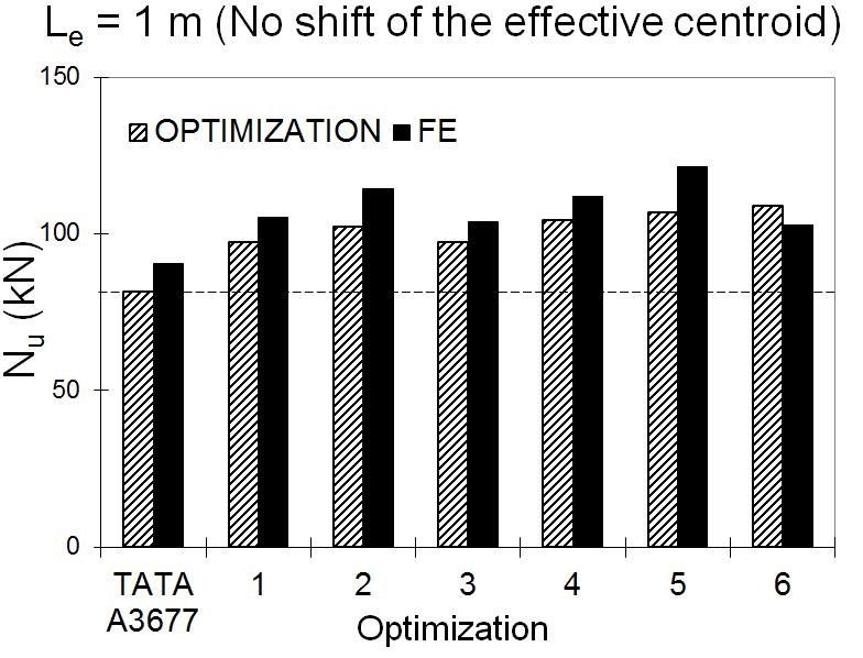


27 Fig. 6. Ultimate capacities in compression 26


28 Fig. 7. Ultimate capacities in bending Fig. 8. Stress-strain curve used in the FE model (a) (b) Uniform end pressure Ux=0 boundary condition is applied to the mid-span and one node is restrained by Uy=Uz=Urx=0 Uniform rotation Ux=0 boundary condition is applied to the mid-span Uy=Uz=Urx=Urz=0 boundary conditions are applied to the reference node Fig. 9. FE models for columns and beams 27