When the Unexpected Occurs: Tendon Failures in the Construction of a New 2 MG Prestressed Concrete Reservoir
|
|
|
- Evelyn Howard
- 5 years ago
- Views:
Transcription


1 When the Unexpected Occurs: Tendon Failures in the Construction of a New 2 MG Prestressed Concrete Reservoir Nancy Kraushaar, P.E., Oregon City Patrick Van Duser, P.E., Black & Veatch
2 Presentation Overview Water Bridge to the Future Project Description Mt. View Reservoir No. 1 Overview of the AWWA D-110 (DYK) Tank Vertical Tendons Description and Function Tendon Failure Event & Response Investigation & Results Theory & Conclusion Recommendations Lessons Learned Mt. View Reservoir No. 2 Post-Tension Video
3 Project Team Water Bridge to the Future Owner City of Oregon City Engineer Black & Veatch, Portland, Oregon Structural Engineer OBEC, Eugene, Oregon Contractor Ward-Henshaw, Canby, Oregon Post-Tensioning DYK, Inc., El Cajon, California

4 Oregon City Mt. View Reservoir No. 1
5 Mt. View Reservoir No. 1 Project Description Replace Existing, Unused In-ground Reservoir 2.0 Million Gallon Capacity 27-foot Wall Height, 117-foot inside Diameter AWWA D-110 and IBC inch Water and 24-inch Storm Piping Appurtenances Construction November 2005 June 2006 Construction Cost - $2,060,000

6 Construction Overview Base Slab

7 Construction Overview - Walls

8 Construction Overview - Columns
9 Construction Overview - Roof
10 Construction Overview Strand Wrapping

11 Construction Overview Shotcrete & Completion

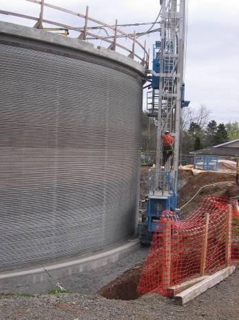
12 Vertical Tendons Description & Function Sleeved in Tank Wall Anchored Top and Bottom Sleeve Grouted after Tensioning Galvanized 26-foot long, 1¼-inch diameter 96 Vertical Tendons in Mt. View Reservoir No. 1

13 Vertical Tendons Description and Function
 Design Elongation 1.")
14 Vertical Tendons Description & Function ASTM 722 Type II Ultimate Tensile Strength 150 ksi Design Load kips Design Stress 107 ksi (70% of Ultimate Strength) Design Elongation inch

15 Vertical Tendons Description and Function
 February 15, 2006")
16 Vertical Tendon Failure - Events Bam! February 13, 2006 Tendon #23 failed at Load = 114 kips (62% Ultimate strength) February 15, 2006 Tendon #3 failed at Load = 107 kips (58% Ultimate strength)

17 Vertical Tendon Failure - Event

18 Vertical Tendon Failure - Response Stop Work Safety First De-stress Other Tendons Notify Owner and Experts - DYK, OBEC Recover Failed Tendons Send to Labs for Analysis Allow Through-can Installation Keep Project on Schedule

19 Vertical Tendon Failure - Response
20 Vertical Tendon Failure - Investigation Ward-Henshaw/DYK Metallurgical Testing of Failed Tendons QA inquiry into Tendon Source, Galvanizer City of Oregon City/Black & Veatch Metallurgical Testing of Failed Tendons (MEI-Charlton in Portland, Oregon) OBEC Calculated Effect of Notch on Tendon Strength

21 Vertical Tendon Failure Results - Metallurgical Tensile strength > ASTM 722 specification Bar Chemical Composition within ASTM 722 specification Microstructure Pearlite Normal
22 Vertical Tendon Failure Results Calculated Load OBEC Calculated 51% Greater Stress at Notch Considered Axial and Bending Stresses Stress Concentrations up to 2.5x More Does Not Rule Out Other Contributors to the Tendon Failure

23 Vertical Tendon Failure - Results Pre-Existing Cracks Found at and near Fracture Surface Galvanizing Found on Crack Surface Tin Found on Crack Surface in Concentration Greater than Allowed

24 Vertical Tendon Failure Results

25 Vertical Tendon Failure - Results
26 Vertical Tendon Failure Results Discussion Tendons loaded to 75% of Ultimate Strength per ASTM 722 at Manufacturer Tendons Failed at < 70% of Ultimate Strength when Loaded On-Site How Were Tendons Damaged Between Loadings? Dropped? Improperly Stored? Something at Galvanizer?
27 Vertical Tendon Failure - Results Hypothesis Liquid Metal Embrittlement (LME) The brittle fracture, or loss in ductility, of a usually ductile metal in the presence of a liquid metal Thomas J. Kinstler Three elements required for this to occur Not as well researched as other brittle fracture phenomena Understood to not worsen with time

28 Vertical Tendon Failure - Results Black & Veatch/OBEC Conclusion Existing cracks led to stress concentrations at the eventual fracture surface. LME may have contributed to the failure of the tendons but it is not conclusive
29 Vertical Tendon Failure - Recommendations Replace Broken Tendons Over-stress All Tendons by 10% Address Subsequent Tendon Failures on Case-by- Case Basis Extend DYK Warranty from 1 year to 2 years Tendon Loading Condition Specified Design Load Reservoir No. 1 10% Over-Load Recommended Standard Yield Strength Type II Bars ASTM 722 Standard Ultimate Tensile Strength ASTM 722 Tested Yield Strength Bar No. 23 (MEI) Tested Tensile Strength - Bar No 23 (MEI) Specified or Resulting Stress (ksi) Percentage of ASTM 722 Ultimate Strength = 150 ksi 105 ksi 70% 116 ksi 77% 120 ksi 80% 150 ksi 100% 135 ksi 90% 161 ksi 107%

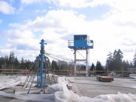
30 Vertical Tendon Failure Implementing the Fix


31 Vertical Tendon Failure Implementing the Fix
32 Mt. View Reservoir No. 1 Lessons Learned Keep Laboratory Results Independent Modify Roof Design to Keep Project on Track DYK Responded Professionally, Knowledgably Secure Assurances Over-stress tendons 2-year Warranty Future Design Consider Not Galvanizing the Tendons

33 City of Oregon City Mt. View Reservoir No. 2

34 Mt. View Reservoir No. 2 Buttress Walls
 6-strand Bundle Loaded to 173 kips (7163 psi)")
35 Mt. View Reservoir No. 2 Post-Tensioned Strand Each Corner Wall Loaded to 750 kips (Total P-Jack) 6-strand Bundle Loaded to 173 kips (7163 psi) 7-strand Bundle Loaded to 202 kips (8363 psi) 11 from Wall Face to Center of Post-tensioned Cable Bundles

36 Mt. View Reservoir No. 2 Post-Tensioned Strand

37 Mt. View Reservoir No. 2 Post-Tensioned Strand

38

39 Mt. View Reservoir No. 1 Questions?