SCREW PILES INFORMATION SHEET
|
|
|
- Francis Pitts
- 5 years ago
- Views:
Transcription

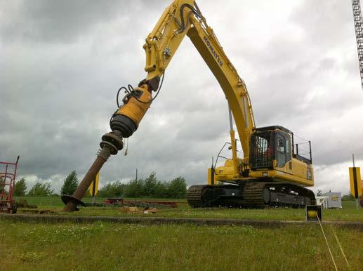
1 INFORMATION SHEET SCREW PILES Screw piles can be used in almost all situations where conventional piled foundations would be specified. They are composite end-bearing/friction piles, well suited for resistance to compression or tension loads, in poor soil conditions by transferring load to high end bearing capacity helical plates. They can also be constantly monitored during installation showing the resistance results. These piles are capable of considerable loads and are suitable for industrial and commercial applications such as underpinning, masts, large signs, retaining structures, houses and portal arch buildings. After use the piles can be removed which makes them highly suitable for temporary structures as they leave no environmental impact. Benefits include: quick installation times, zero vibration, no spoil, minimal noise levels, completely portable and ideal for low headroom situations u-knightconstruction.co.uk


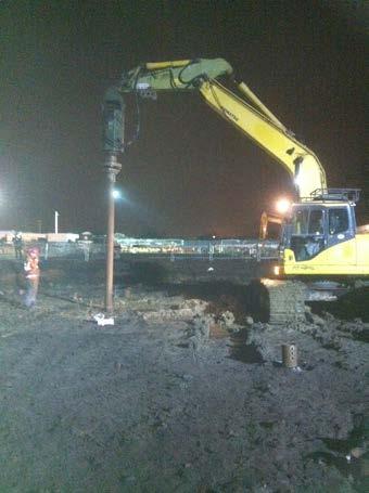
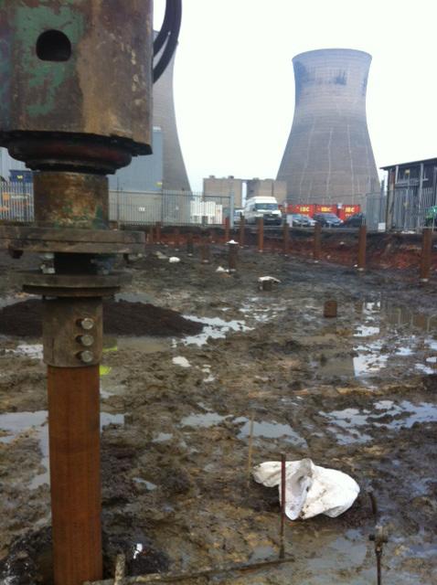
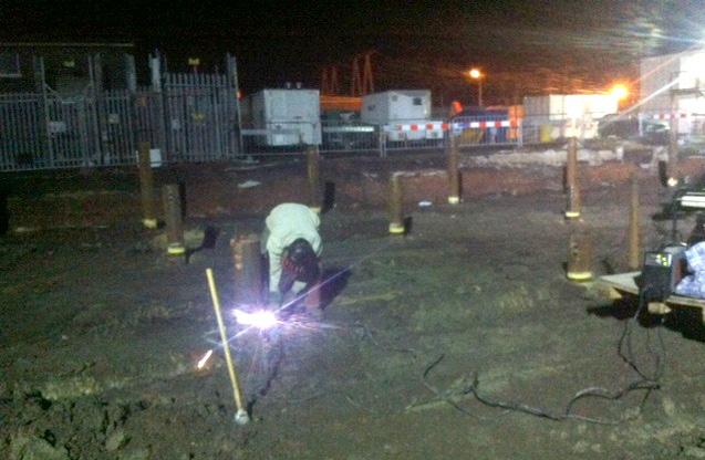
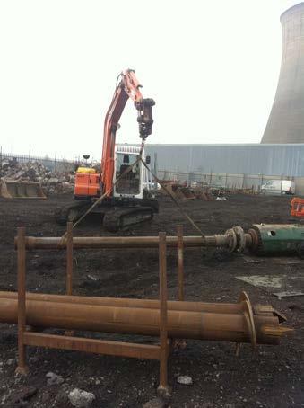
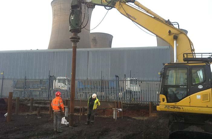
2 CASE STUDY 1 Client: Doncaster Power Station Purpose: Switch room base Ground conditions: Clay for 11m Pile type: 219mm to a depth of 12m Quantity: 58 Additional work: None Completed: 10 days This work was carried out in close proximity to the functioning transformers therefore a conventional CFA rig could not be used. The excessive vibrations and possibility of the rig tipping over was a concern for the client. Screw piles were a perfect option as they produce little or no vibration and the low height of the rig prevents a topple. 58 piles were expected to reach a depth of 12 metres using four metre sections, However issues were encountered with the undulating stone strata beneath the upper soils at varying levels. In some cases required torque levels were achieved much sooner and piles had to be terminated. Piles are marked, and using either oxy propane or plasma cutter, are cut to the required height and completed as normal with a top hat. The client applied the specified reinforcement and cast a 600mm concrete slab.
3


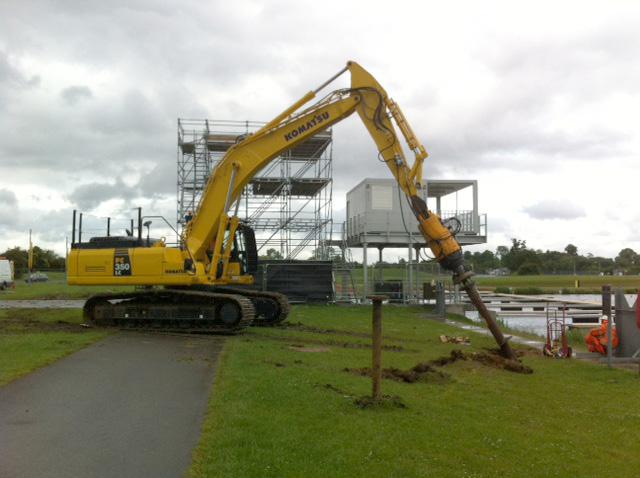
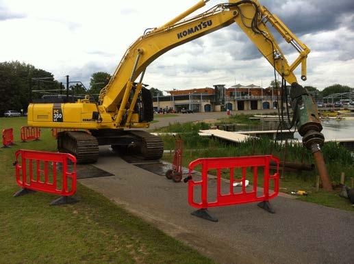
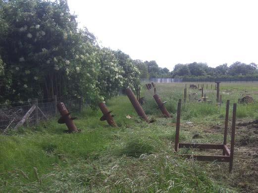
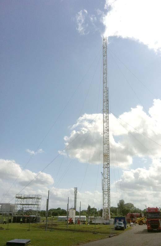
4 CASE STUDY 2 Client: Eaton Dorney Lake Purpose: Temporary masts Ground conditions: Gravels Pile type: 219 and 240mm to a depth of 8m Quantity: 28 Additional work: Remove all piles As part of the 2012 Olympic coverage two temporary 100m masts were required. They held a cable that ran the length of the lake (1.4 miles) which a TV camera ran along. Ten Piles were required per base with an additional four anchor piles driven in at 45 degrees. These have now been removed without a trace and without impact on the environment. Completed: 10 days
5


6 CASE STUDY 3 Client: Autoguide Purpose: Solar Farm bases Ground conditions: Clay Pile type: 60mm to a depth of 1.5m Quantity: 60 Additional work: 30m Trench Completed: 3 Days The installation of this Solar Farm required a gridded base system. The client faced problems due to the highly shrinkable clays in the area. A Concrete raft had been considered but due to high ground work costs, the possibility of the concrete fracturing and movement affecting the panels, they chose screw piles. As the screw pile penetrates far below the shrinkable top layer the possibility of movement is eliminated. These proved the ideal solution.

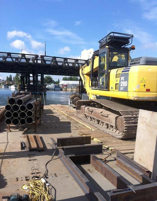
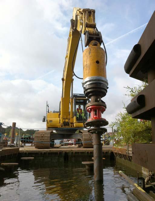
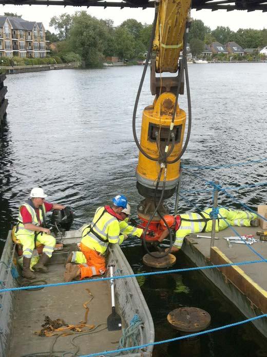
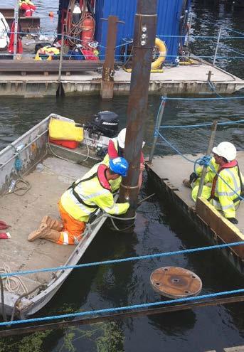
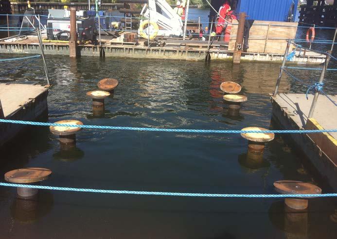
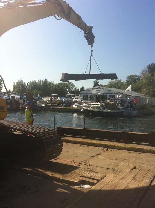
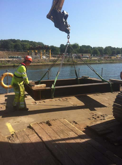
7 CASE STUDY 4 Client: Costain Purpose: Walton on Thames bridge Ground conditions: River bed Pile type: 219mm to a depth of 14m Quantity: 16 Additional work: Remove piles Completed: 10 days This project required the installation of supports for a temporary suspension bridge. Screw piles were chosen for this project as they can be removed after use. Other methods would have involved greater expense to the client and the environment. Each base consisted of eight piles at 14 metre depth using 219mm diameter piles, bolted together in two metre sections. Four piles were driven vertically and four were driven at a 30 degree rake. Once complete the piles were braced below the water by divers. Overall accuracy for pile centres was 25-30mm. Due to the weight of the bridge it was prefabricated and brought to site in two sections. The sections were lowered one at a time to rest on the Screw piled bases. The two sections were bolted and welded together.
8
9