[Amdt , 60 FR 50336, Sept. 28, 1995; 60 FR 54409, Oct. 23, 1995, as amended at 69 FR 3696, Jan. 26, 2004; 70 FR 56099, Sept.
|
|
|
- Lee Wright
- 5 years ago
- Views:
Transcription
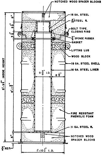
1 Subpart K Specifications for Packagings for Class 7 (Radioactive) Materials Specification 7A; general packaging, Type A. (a) Each packaging must meet all applicable requirements of subpart B of part 173 of this subchapter and be designed and constructed so that it meets the requirements of , , , and of this subchapter for Type A packaging. (b) Each Specification 7A packaging must be marked on the outside USA DOT 7A Type A. (c) Each Specification 7A packaging must comply with the marking requirements of In paragraph 178.3(a)(2), the term packaging manufacturer means the person certifying that the package meets all requirements of this section. [Amdt , 60 FR 50336, Sept. 28, 1995; 60 FR 54409, Oct. 23, 1995, as amended at 69 FR 3696, Jan. 26, 2004; 70 FR 56099, Sept. 23, 2005] Specification 20PF phenolic-foam insulated, metal overpack General requirements. (a) Each overpack must meet all of the applicable requirements of of this subchapter. (b) The maximum gross weight of the package, including the inner cylinder and its contents, must not exceed the following: (1) Specification 20PF kg (300 pounds). (2) Specification 20PF kg (700 pounds). (3) Specification 20PF kg (1000 pounds). (c) The general configuration of the overpack must be a right cylinder, consisting of an insulated base section, a steel liner lid, and an insulated top section. The inner liner and outer shell must be at least 16-gauge and 18-gauge steel, respectively, with the intervening cavity filled with a molded-in-place, fire-resistant, phenolic-foam insulation interspersed with wooden members for bracing and support Wood pieces must be securely attached to both the liner and shell. No hole is permitted in the liner. Each joint between sections must be stepped a minimum of 5 cm (2 inches) and gaps between mating surfaces must not exceed 5 mm (0.2 inch). Gaps between foam surface of top section and liner lid must not exceed 1 cm (0.4 inch) or 5 cm (2 inches) where taper is required for mold stripping. For the specification 20PF 1, the top section may consist of a plug of foam insulation and a steel cover. The liner and shell closures must each be gasketed against moisture penetration. The liner must have a bolted flange closure. Shell closure must conform to paragraph (d) of this section. (d) Drums over 5 gallons capacity must be closed by means of 12-gauge bolted ring with drop forged lugs, one of which is threaded, and having 3/8 inch bolt and nut for drums not over 30 gallons capacity and 5/8 inch bolt and nut for drums over 30 gallons capacity. Five gallon drums must be of lug type closure with cover having at least 16 lugs. (e) Drawings in DOE CAPE 1662, Rev. 1 and Supplement 1 (IBR, see of this subchapter), which include bills of material, are a part of this specification. [Amdt , 39 FR 45247, Dec. 31, Redesignated by Amdt , 55 FR 52716, Dec. 21, 1990; 65 FR 58632, Sept. 29, 2000; 66 FR 45386, 45389, Aug. 28, 2001; 68 FR 75757, Dec. 31, 2003] Materials of construction and other requirements. (a) Phenolic foam insulation must be fire-resistant and fabricated in accordance with USDOE Material and Equipment Specification
2 SP 9, Rev. 1 and Supplement (IBR, see of this subchapter), which is a part of this specification. (Note: Packagings manufactured under USAEC Specification SP 9 and Rev. 1 thereto are authorized for continued manufacture and use.) A 13.7 cm (5.4-inch) minimum thickness of foam must be provided over the entire liner except: (1) Where wood spacers replace the foam; or (2) At protrusions of liner or shell, such as flanges, baffles, etc., where minimum insulation thickness is 9 cm (3.5 inches); or (3) Where alternate top section (specification 20PF 1) is used. Foam must not interfere with proper seating of screws in inner liner flange assembly. Average density of insulation must be 0.13 g/cc (8 pounds per cubic foot (pcf)) minimum for bottom section and 0.16 g/cc (10 pcf) minimum for top section, except 0.1 g/cc (6.5 pcf) for the specification 20PF 1 top section. (b) Gaskets must be as follows: (1) Inner liner flange Neoprene rubber of 30 to 60 type A durometer hardness or other equivalent gasket material which is compatible with the specific contents. (2) Outer shell Synthetic rubber conforming to MIL-R-6855 (available from the Naval Publications Forms Center, 5801 Tabor Avenue, Philadelphia, Pennsylvania 19120) class 2, grade 60. (3) Support and pressure pads for inner liner top and bottom must be sponge rubber or equivalent. (c) Alternate top section (specification 20PF 1 only). Average insulation density must be 0.16 g/cc (10 pcf minimum). Thickness of plug must be 11 cm (4.3 inches) minimum, except thickness may be reduced to 10 cm (4 inches) to clear bolt heads. A flush mounted top lifting device must be securely fastened to a wood block encapsulated by the foam. (d) Vent holes 5 mm (0.2-inch) diameter must be drilled in the outer shell to provide pressure relief during the insulation foaming and in the event of a fire. These holes, which must be drilled in all areas of the shell that mate with the foam insulation, must be spaced in accordance with DOE CAPE 1662, Rev. 1 and Supplement 1 (IBR, see of this subchapter). (e) Welding must be by a fusion welding process in accordance with American Welding Society Codes B 3.0 and D 1.0 (IBR, see of this subchapter). Body seams and joints for the liner or shell must be continuous welds. (f) Waterproofing. Each screw hole in the outer shell must be sealed with appropriate resin-type sealing material, or equivalent, during installation of the screw. All exposed foam surfaces, including any vent hole, must be sealed with waterproofing material as prescribed in USDOE Material and Equipment Specification SP 9, Rev. 1 and Supplement, or equivalent. [Amdt , 39 FR 45247, Dec. 31, 1974, as amended by Amdt , 44 FR 49458, Aug. 23, Redesignated by Amdt , 55 FR 52716, Dec. 21, 1990; 66 FR 45387, Aug. 28, 2001; 68 FR 75757, Dec. 31, 2003] Tests. (a) Leakage test Each inner liner assembly must be tested for leakage prior to installation. Seam welds of the liner must be covered for a distance of at least 15 cm (6 inches) on either side of the seam with soapsuds, heavy oil, or equivalent material, and interior air pressure applied to at least 776 mm Hg (15 p.s.i.g.) above atmospheric pressure must be held for at least 30 seconds. Liners failing to pass this test may not be used until repairs are made, and retests successfully passed. (b) [Reserved] [Amdt , 39 FR 45247, Dec. 31, Redesignated by Amdt , 55 FR 52716, Dec. 21, 1990; 66 FR 45387, Aug. 28, 2001; 67 FR 61016, Sept. 27, 2002] Required markings.
3 (a) Marking must be as prescribed in (b) Marking on the outside of each overpack must be as follows: (1) USA-DOT-20PF-1 or 2, as appropriate, and if the entire liner is made of stainless steel, additional marking such as 3041 SS to indicate the type of stainless steel used. (2) TARE WT: xxx lbs. where xxx is the tare weight of the assembled overpack without the inner container. (3) Year of manufacture. [Amdt , 39 FR 45247, Dec. 31, Redesignated by Amdt , 55 FR 52716, Dec. 21, 1990, as amended at 63 FR 37462, July 10, 1998] Typical assembly detail. (a) Specifications 20PF 1. (b) Specification 20PF 2.
4 (c) Specification 20PF 3.
5 [Amdt , 39 FR 45247, Dec. 31, Redesignated by Amdt , 55 FR 52716, Dec. 21, 1990] Specification 21PF fire and shock resistant, phenolic-foam insulated, metal overpack General requirements. (a) Each overpack must meet all of the applicable requirements of , , and of this subchapter. (1) Specification 21PF 1 overpacks includes the series of 21PF 1, 21PF 1A, and 21PF 1B models. Details of the three models are included in DOE CAPE 1662, Rev. 1 and Supplement 1 (IBR, see of this subchapter). (2) Drawings in CAPE 1662, Rev. 1 and Supplement 1, that include bills of materials, and KSS 471 (IBR, see of this subchapter), are a part of this specification. (b) Each overpack is authorized for use in applications where the maximum gross weight of the package, including the inner container and contents does not exceed 3725 kg (8200 pounds), (horizontally-loaded specification 21 PF 1 unit), or 3900 kg (8600 pounds), (end-loaded specification 21 PF 2 unit).
6 (c) The general configuration of the overpack must be a right cylinder, consisting of a steel inner liner (at least 16-gauge) and steel outer shell (at least 14-gauge) with the intervening cavity filled with a molded-in-place, fire-resistant, phenolic foam insulation and interspersed wooden members for bracing and support. Two specific configurations are authorized; a horizontal loading unit (specification 21PF 1) consisting of insulated base and top sections jointed in a longitudinal peripheral closure joint; or an endloading unit (specification 21PF 2), consisting of an insulated main section, a steel plate liner lid, and an insulated end cap. For either type each joint between sections must be stepped at least 1.8 cm (0.75-inch) and gaps between mating surfaces may not exceed 5 mm (0.2-inch). Bolted closures, which must each be gasketed against moisture penetration, must be in accordance with CAPE Each bolt must be equipped with a locking device to prevent loosening from vibration. Outer steel bracing and support framework must be attached to the shell to facilitate normal handling. (d) Specification 21PF 1 overpacks in use or under construction before April 1, 1989, must be modified to Specification 21PF 1A before April 1, All new construction to Specification 21PF 1 beginning after March 31, 1989, must meet Specification 21PF 1B. Use of unmodified 21PF 1 overpacks after March 31, 1991, is prohibited. [Amdt , 39 FR 45250, Dec. 31, 1974; 40 FR 2435, Jan. 13, 1975, as amended by Amdt , 53 FR 36551, Sept. 20, Redesigntated by Amdt , 55 FR 52716, Dec. 21, 1990; 66 FR 45387, Aug. 28, 2001; 68 FR 75757, Dec. 31, 2003] Materials of construction and other requirements. (a) Phenolic foam insulation must be fire resistant and fabricated in accordance with USDOE Material and Equipment Specification SP 9, Rev. 1 and Supplement (IBR, see of this subchapter), which is a part of this specification. (Note: Packagings manufactured under USAEC Specification SP 9, and Rev. 1 thereto are authorized for continued manufacture and use.) A 14 cm (5.5-inch) minimum thickness of foam must be provided over the entire liner except where: (1) Wood spacers replace the foam material; or (2) At protrusions of liner or shell, such as flanges, baffles, etc., where the minimum thickness of foam, wood, or a combination of these is 10 cm (4 inches). (3) Solid wood or laminated wood solidly glued may be used to replace the foam between liner and shell (i.e., in ends of overpack). In this case, minimum wood thickness is 10 cm (4 inches). Average density of insulation must be 0.1g/cc (6.75 pounds per cubic foot (pcf)) minimum, except that 0.13 g/cc (8 pcf) is required in the removable end cap of the specification 21PF 2, which must have a minimum foam thickness of 12.7 cm (5 inches). (b) Gaskets for inner liner, outer shell, or where otherwise specified in DOE CAPE 1662, Rev. 1 (IBR, see of this subchapter), must be as specified in DOE CAPE 1662, Rev. 1. (c) Support and pressure pads for the inner liner must be of neoprene, sponge rubber, or equivalent. (d) Fire-retardant (intumescent) paint must be applied to any wood blocking which is located at any joint in the shell. (e) Vent holes 5 mm (0.2-inch) diameter must be drilled in the outer shell to provide pressure relief during the insulation foaming and in the event of a fire. These holes, which must be drilled in all areas of the shell which made with the foam insulation, must be spaced in accordance with CAPE (f) Welding must be by a fusion process in accordance with the American Welding Society Codes B 3.0 and D 1.0 (IBR, see of this subchapter). Body seams and joints for the liner and shell must be continuous welds. (g) Waterproofing. Each screw hole in the outer shell must be sealed with appropriate resin-type sealing material, or equivalent, during installation of the screw. All exposed foam surfaces, including any vent hole, must be sealed with either: (1) Waterproofing material as prescribed in USDOE Material and Equipment Specification SP 9, Rev. 1 and Supplement, or (2) As specified in CAPE 1662, Revision 1.
7 [Amdt , 39 FR 45250, Dec. 31, 1974, as amended by Amdt , 44 FR 49459, Aug. 23, 1979; Amdt , 53 FR 36551, Sept. 20, Redesigntated by Amdt , 55 FR 52716, Dec. 21, 1990; 66 FR 45387, Aug. 28, 2001; 68 FR 75757, Dec. 31, 2003] Modification of Specification 21PF 1 overpacks. (a) Each Specification 21PF 1 overpack for which construction began or was completed before April 1, 1989, in conformance with drawing E-S J, Rev. 1 of DOE CAPE 1662 (IBR, see of this subchapter), must be modified in conformance with drawing S1E J1 D of DOE CAPE 1662, Rev. 1, Supplement 1, before April 1, (b) Each such existing Specification 21PF 1 overpack must be dried and weighed in accordance with the following procedures: (1) Drill out or otherwise clean the plug material from the vent holes originally provided for foam expansion. See drawing S1E J1 D of CAPE 1662, Revision 1, Supplement 1, for locations. (2) Weigh each packaging element (top and bottom halves) separately to an accuracy of ±2.3 kg (±5 pounds) and record the weights. If this measured weight exceeds the initially measured weight at the time of fabrication by 11.3 kg (25 pounds) (indicating a significant retained water content), the packaging element must be dried. (3) Place overpack element in drying oven; maintain temperature between C (190 and 210 F) for a minimum of 72 hours. The oven should have a provision for air exchange or other means of removing moisture driven from the foam structure. (4) Drying may be discontinued after 72 hours if the weight of the packaging element does not exceed the initially measured tare weight of that element at the time of fabrication by more than 11.3 kg (25 pounds). If the weight of the packaging element exceeds the initial fabricated weight (indicating a significant remaining water content) by more than 11.3 kg (25 pounds), drying must be continued until the weight differential is not higher than 11.3 kg (25 pounds), or until the rate of weight loss is less than 1.1 kg (2.5 pounds) per day. (5) As an alternate moisture measurement, a calibrated moisture meter reading for 20 percent maximum water content may be used to indicate an end point in the drying cycle, which is detailed in report Renovation of DOT Specification 21PF 1 Protective Shipping Packages, Report No. K 2057, Revision 1, November 21, 1986, available from the USDOE and part of USDOE Report No. KSS 471 (IBR, see of this subchapter). (6) Following drying, each overpack element (top and bottom halves) must be weighed and the weight in both pounds and kilograms must be engraved on the identification plate required by (c). (c) After modification as provided for herein, each Specification 21PF 1 overpack must be marked USA-DOT-21PF-1A. See the marking requirements of [Amdt , 53 FR 36551, Sept. 20, Redesigntated by Amdt , 55 FR 52716, Dec. 21, 1990; Amdt , 60 FR 49111, Sept. 21, 1995; 63 FR 37462, July 10, 1998; 66 FR 45389, Aug. 28, 2001; 68 FR 75757, Dec. 31, 2003] Construction of Specification 21PF 1B overpacks. (a) Each Specification 21PF 1 overpack for which construction began after March 31, 1989, must meet the requirements of Specification 21PF 1B, in conformance with drawings E-S J-P, and S1E J2 B of DOE CAPE 1662, Rev. 1, Supplement 1 (IBR, see of this subchapter). (b) With the exception of the closure nuts and bolts, all metal parts of the Specification 21PF 1B must be of stainless steel as shown on the drawings referred to in paragraph (a) of this section. [Amdt , 53 FR 36551, Sept. 20, Redesigntated by Amdt , 55 FR 52716, Dec. 21, 1990; 68 FR 75757, Dec. 31, 2003]
 For Specifications 21PF 1 and 21PF 2 only, if the inner shell is constructed of stainless steel, additional marking such as 304L- SS are to be marked on the outside of the overpack to indicate")
8 Required markings. (a) Markings must be as prescribed in (b) Specification marking on the outside of each overpack must be as follows: USA-DOT-21PF-1, 1A, 1B, or 2, as appropriate. (1) For Specifications 21PF 1 and 21PF 2 only, if the inner shell is constructed of stainless steel, additional marking such as 304L- SS are to be marked on the outside of the overpack to indicate the type of stainless steel used. (2) For Specification 21PF 1 and 21PF 2 only, TARE WT: * * * lbs. ( * * * kg) where * * * is the tare weight in pounds and kilograms, respectively, of the assembled overpack without the inner product container. (3) For Specification 21PF 1A and 21PF 1B only: TARE WT. of Cover: * * * lbs ( * * * kg) TARE WT. of BOTTOM: * * * lbs ( * * * kg) where * * * is the tare weight in pounds and kilograms, respectively, of the separate halves of the overpack without the inner product container. For Specification 21PF 1A overpacks, the previous tare weight must be changed to reflect the modified tare weight value or must be covered or removed. (4) Year of manufacture followed by the year of modification, if applicable. (5) The name or symbol of maker or party certifying compliance with specification requirements. A symbol, if used, must be registered with the Associate Administrator. (c) For Specification 21PF 1A and 1B only, the markings required by this section must be affixed to each overpack by inscription upon a metal identification plate 11 inches wide 15 inches long (28 cm 38 cm), fabricated of 16 to 20 gauge stainless steel sheet, ASTM A 240/A 240M (IBR, see of this subchapter), Type 304L. [Amdt , 53 FR 36552, Sept. 20, Redesigntated by Amdt , 55 FR 52716, Dec. 21, 1990, and amended at Amdt , 56 FR 66287, Dec. 20, 1991; 63 FR 37462, July 10, 1998; 66 FR 45386, Aug. 28, 2001; 67 FR 51660, Aug. 8, 2002; 68 FR 75748, Dec. 31, 2003; 69 FR 54046, Sept. 7, 2004] Typical assembly detail. (a) Specification 21PF 1 (horizontal loading overpack). (b) Specification 21PF 1A and 21PF 1B (horizontal loading overpack).
9 (c) Specification 21PF 2 (end loading overpack).
10 [Amdt , 53 FR 36552, Sept. 20, Redesignated by Amdt , 55 FR 52716, Dec. 21, 1990] Specification 2R; inside containment vessel General requirements. (a) Each vessel must be made of stainless steel, malleable iron, or brass, or other material having equivalent physical strength and fire resistance. (b) Each vessel must meet all of the applicable requirements of (c) and (d) of this subchapter. Letters and numerals at least 6 mm (1/4-inch) in height are authorized for the marking of a vessel not exceeding 5 cm (2 inches) inside diameter. [Amdt , 39 FR 45245, Dec. 31, Redesignated by Amdt , 55 FR 52716, Dec. 21, 1990; 66 FR 45387, Aug. 28, 2001] Manufacture. The ends of the vessel must be fitted with screw-type closures or flanges (see ), except that one or both ends of the vessel may be permanently closed by a welded or brazed plate. Welded or brazed side seams are authorized. [Amdt , 39 FR 45245, Dec. 31, Redesignated by Amdt , 55 FR 52716, Dec. 21, 1990, as amended at 63 FR 37462, July 10, 1998]
11 Dimensions. (a) The inside diameter of the vessel may not exceed 30 cm (12 inches) exclusive of flanges for handling or fastening devices and must have wall thickness and length in accordance with the following: Inside diameter maximum Threaded closure Length maximum Inches Cm Inches Mm Wall thickness minimum Flanged closure Inches Cm 2 5 3/ Not less than that prescribed for schedule 40 pipe / / (b) [Reserved] [Amdt , 39 FR 45245, Dec. 31, Redesignated by Amdt , 55 FR 52716, Dec. 21, 1990; 66 FR 45387, Aug. 28, 2001] Closure devices. (a) Each closure device must be as follows: (1) Screw-type cap or plug; number of threads per inch must not be less than United States standard pipe threads and must have sufficient length of thread to engage at least 5 threads when securely tightened. Pipe threads must be luted with an appropriate non-hardening compound which must be capable of withstanding up to 149 C (300 F) without loss of efficiency. Tightening torque must be adequate to maintain leak tightness with the specific luting compound. (2) An opening may be closed by a securely bolted flange and leak-tight gasket. Each flange must be welded or brazed to the body of the 2R vessel per (ANSI) Standard B16.5 or (AWWA) Standard C207 55, section 10 (IBR, see of this subchapter). A torque wrench must be used in securing the flange with a corresponding torque of no more than twice the force necessary to seal the selected gasket. Gasket material must be capable of withstanding up to 149 C (300 F) without loss of efficiency. The flange, whether of ferrous or nonferrous metal, must be constructed from the same metal as the vessel and must meet the dimensional and fabrication specifications for welded construction as follows: (i) Pipe flanges described in Tables 13, 14, 16, 17, 19, 20, 22, 23, 25 and 26 of ANSI B16.5 (IBR, see of this subchapter). (ii) For nominal pipe sizes, 6, 8, 10, and 12 inches, AWWA Standard C207 55, Table 1, class B, may be used in place of the tables prescribed by paragraph (a)(2)(i) of this section. (iii) Sizes under 6 inches, nominal pipe size, the following table with the same configuration as illustrated in AWWA C207 55, Table 1, class B, may be used in place of paragraph (a)(2)(i) of this section. Nominal pipe size Flange O.D. Bolt circle diameter Diameter of bolts Flange thickness Inches Cm Inches Cm Number of bolts Inches Cm Inches Cm Inches Cm / / / / / /2 5/ / /2 5/8 3 1/ / /2 5/ / /2 5/8
12 / /2 5/8 (iv) Cast iron flanges prohibited. (b) [Reserved]