PROJECT INFORMATION. 1.1 Site Location. October 4, Jerry Schwab/President 315 Aden Ave., Suite 26 Glendale, CA 91203
|
|
|
- Pearl Parker
- 5 years ago
- Views:
Transcription
1 October 4, 2017 Jerry Schwab/President 315 Aden Ave., Suite 26 Glendale, CA P: E: Re: Geotechnical Engineering Letter Report VAMC Bldg 202 Domiciliary C-D Entryway Teague Place Temple, Texas Terracon Project No Dear Mr. Schwab: Terracon is pleased to submit our Geotechnical Engineering Letter Report for the proposed construction of VAMC Bldg 202 Domiciliary C-D Entryway in Temple, Texas. This project was authorized by Mr. Jerry Schwab, through signature of our Agreement for Services on September 22, The project scope was performed in general accordance with Terracon Proposal No. P , Revision 1 dated September 22, As you are aware, Terracon previously provided geotechnical engineering design recommendations for four separate projects within the VA campus. Two of those projects (Terracon Projects and ) were solely for new paving and two of those projects (Terracon Projects and ) included building foundations. The closest borings from those previous projects are located between about 600 and 900 feet to the west/northwest of the subject area. The borings from the four previous projects have been utilized to provide design recommendations for the current project. PROJECT INFORMATION 1.1 Site Location Item Location Existing Improvements Current Ground Cover Existing Topography Description The project site is located on the north side of Domiciliaries C and D within the VA campus in Temple, Texas. (See Exhibit A-1). Existing buildings, sidewalks, retaining walls, and paving. Concrete flatwork and walls, interspersed with landscaping. Unknown at this time. Responsive Resourceful Reliable
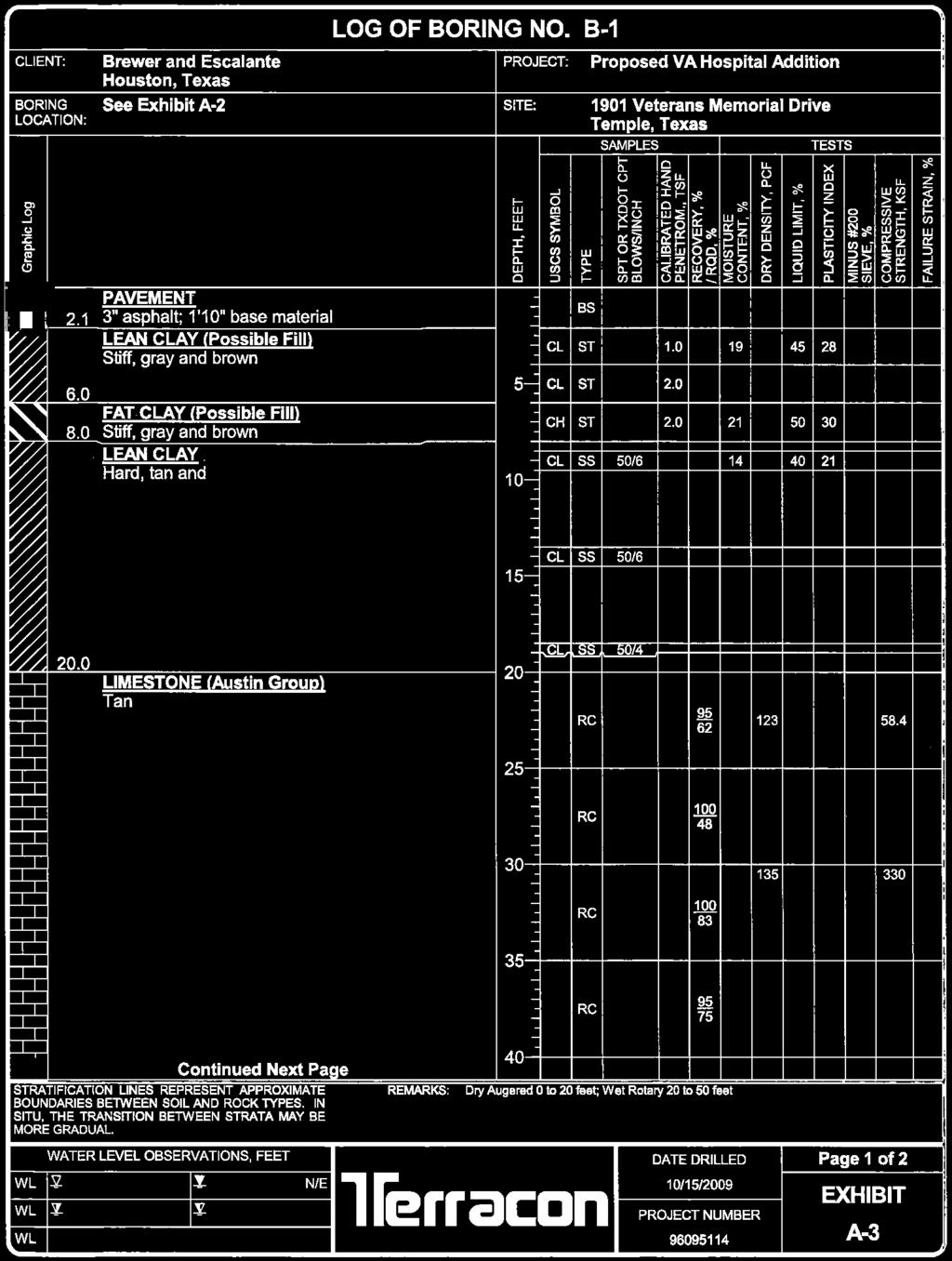
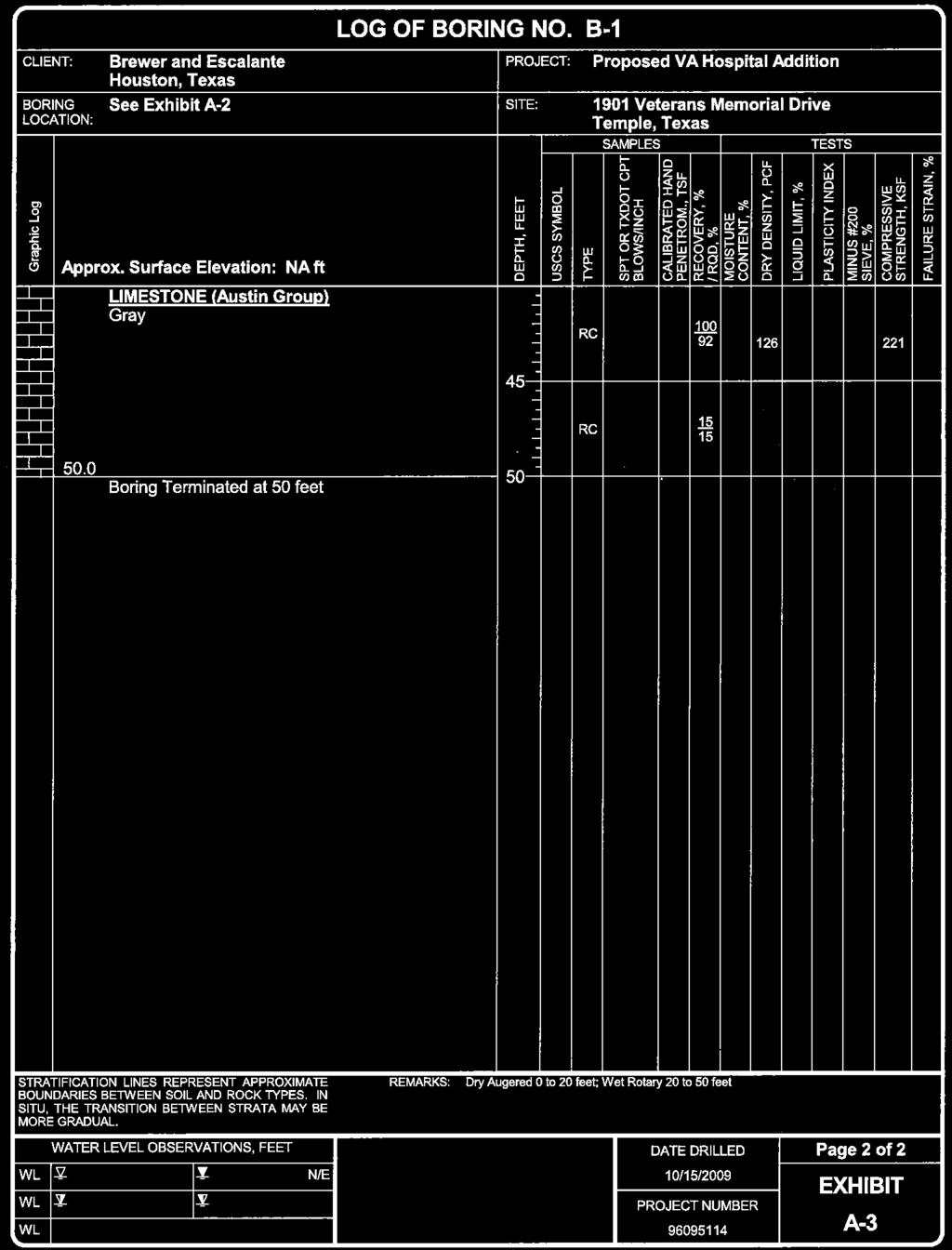
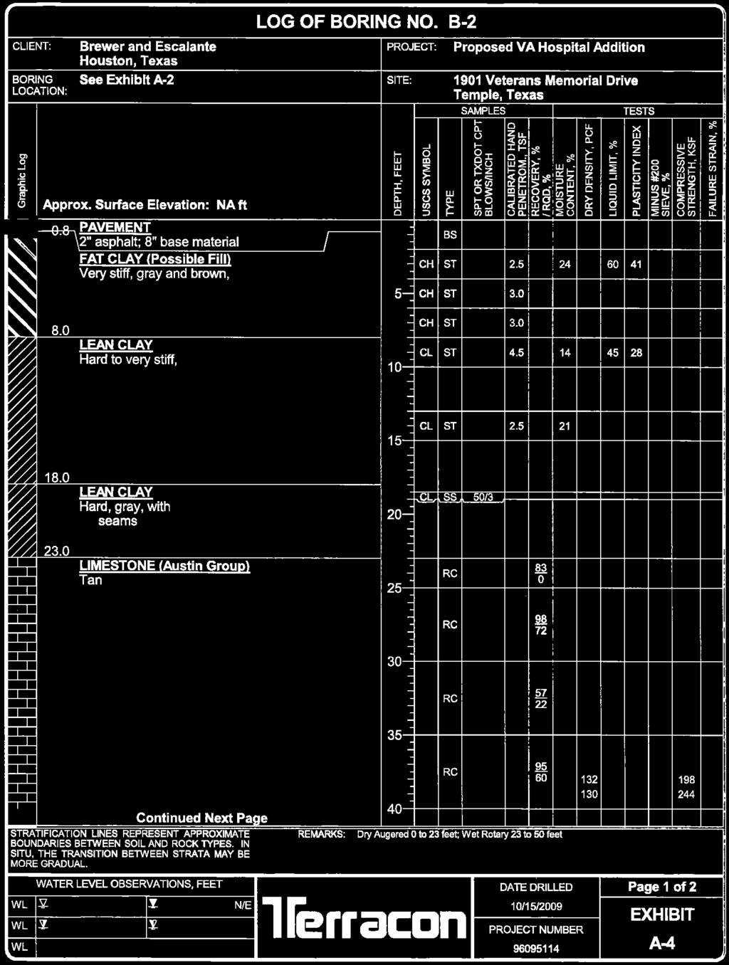
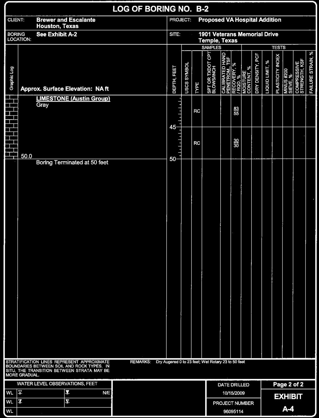
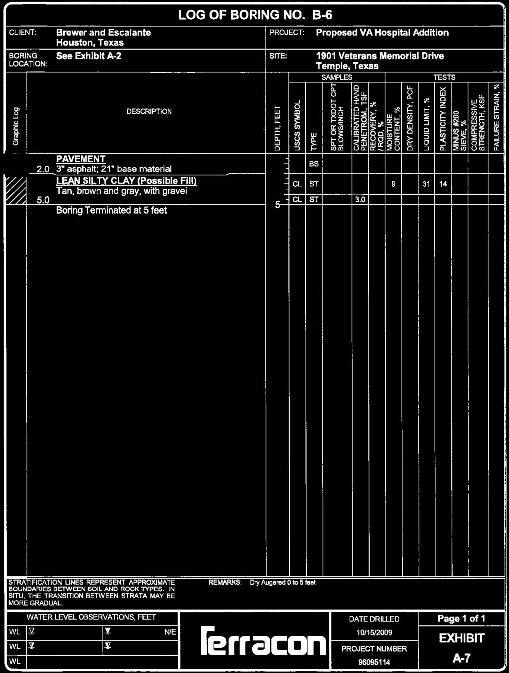
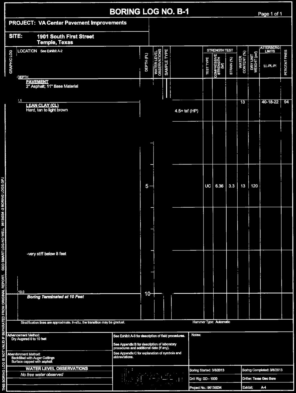
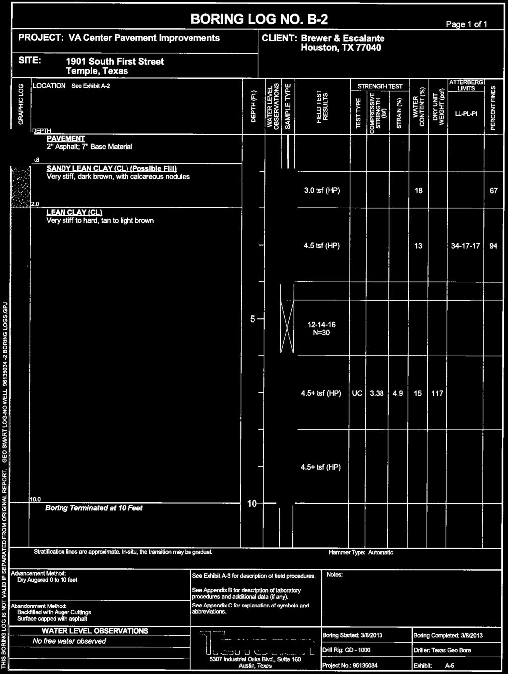
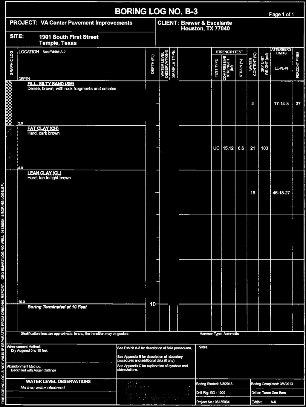
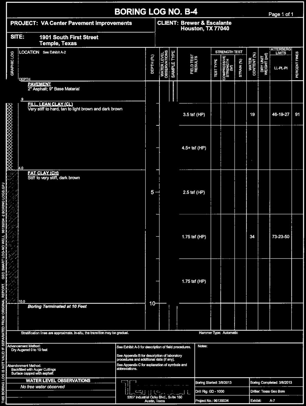
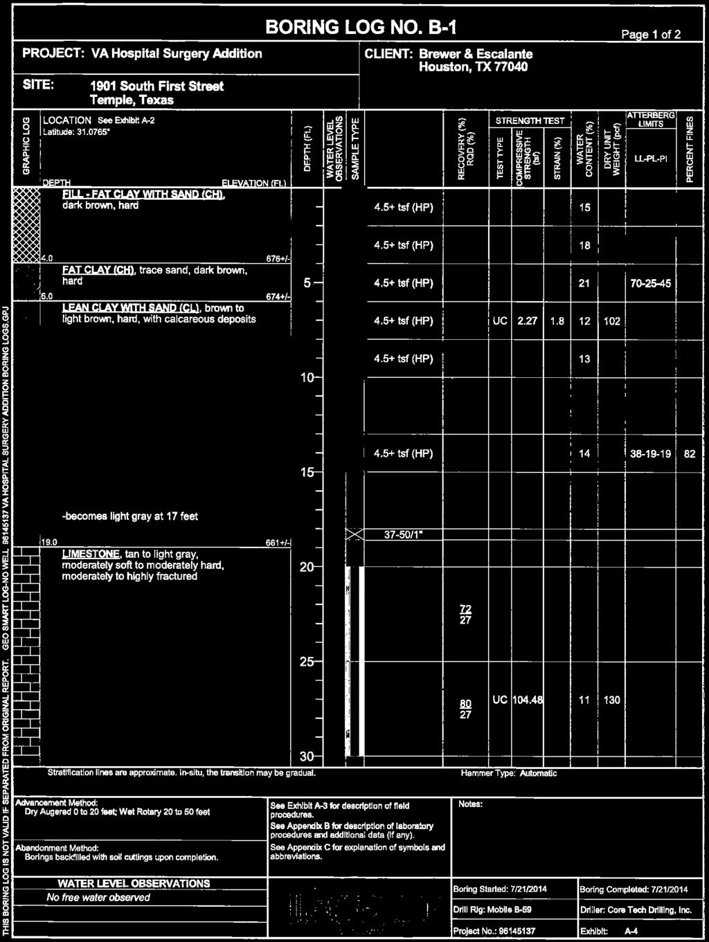
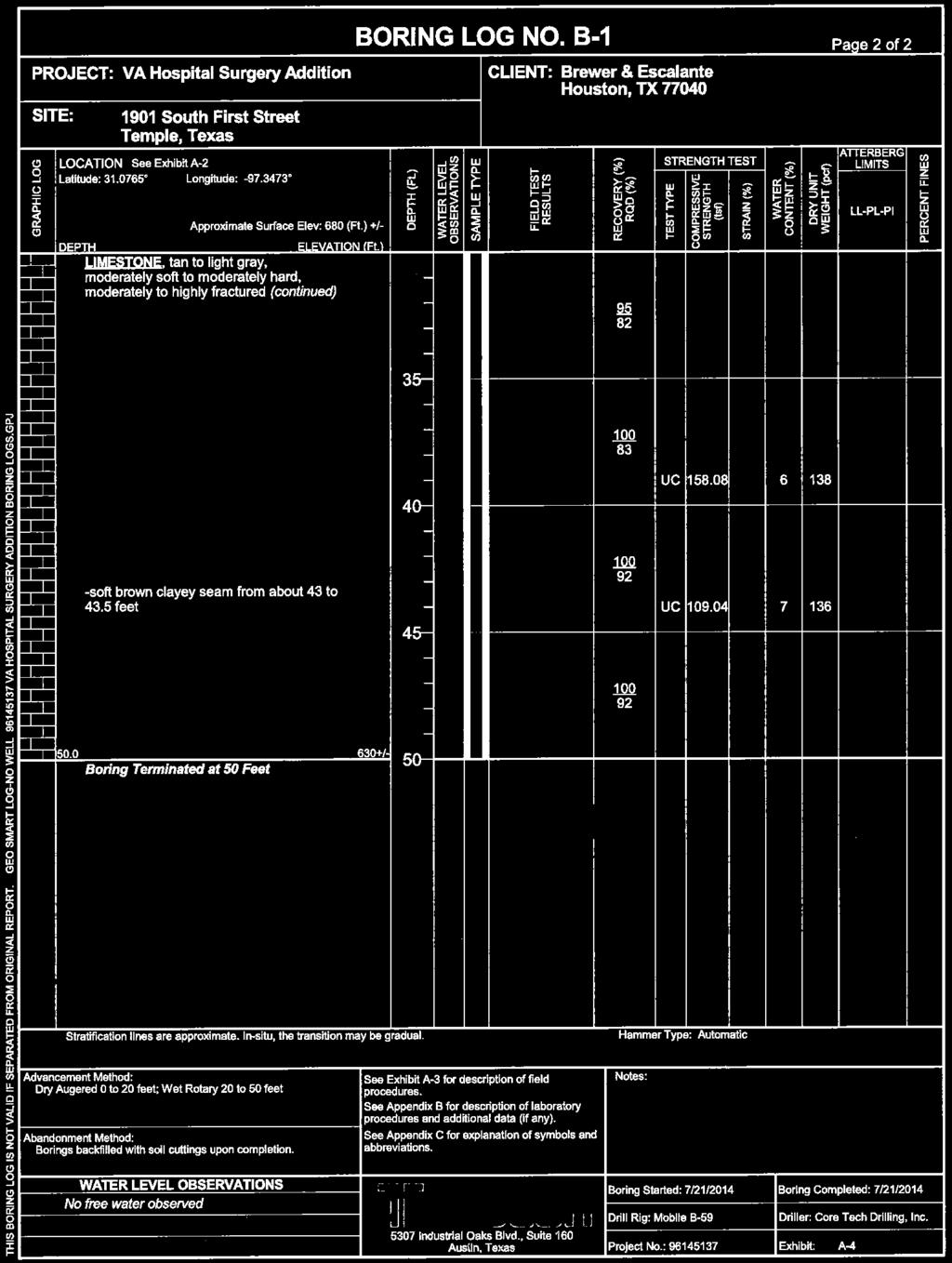
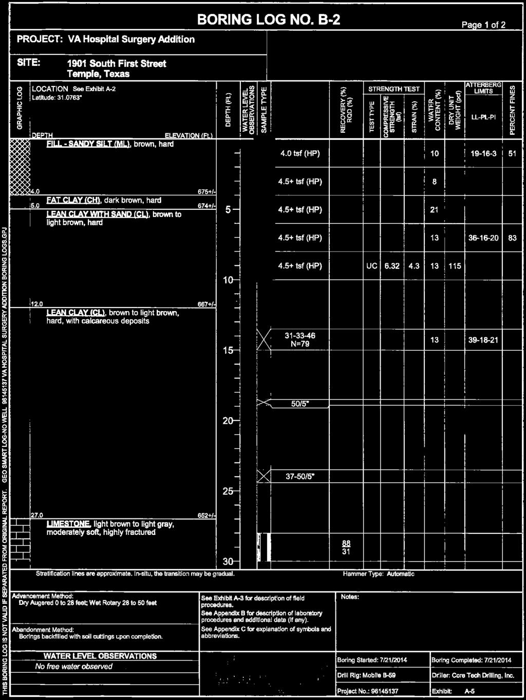
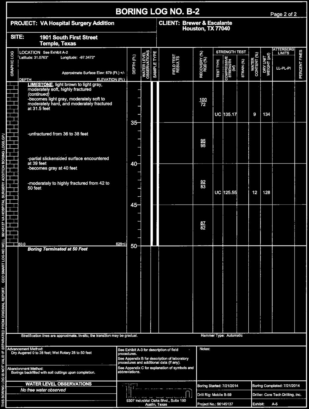
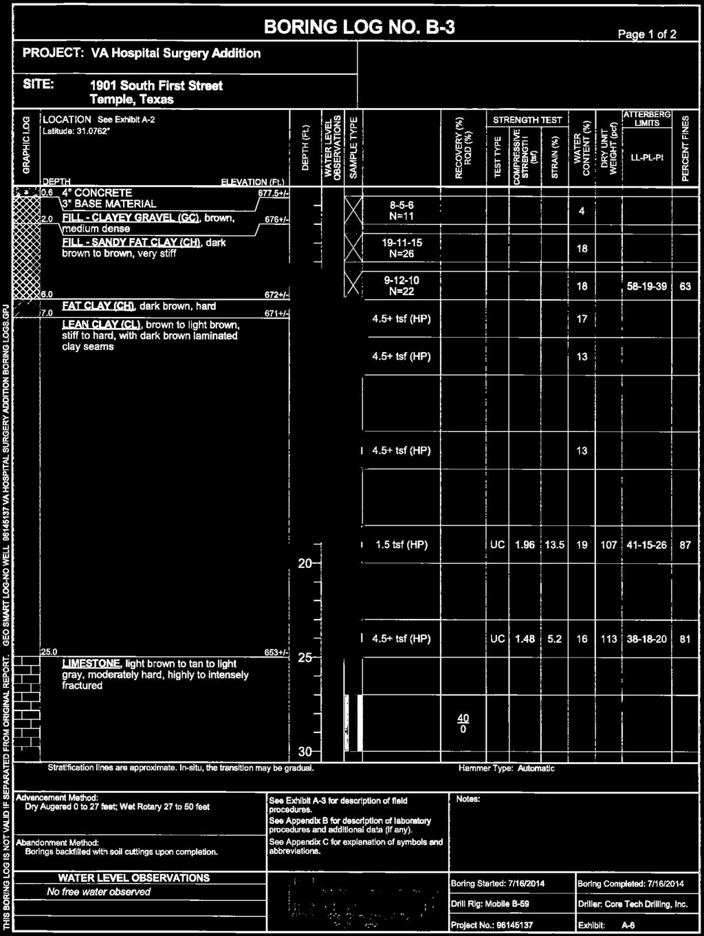
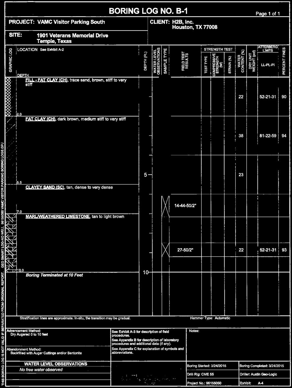
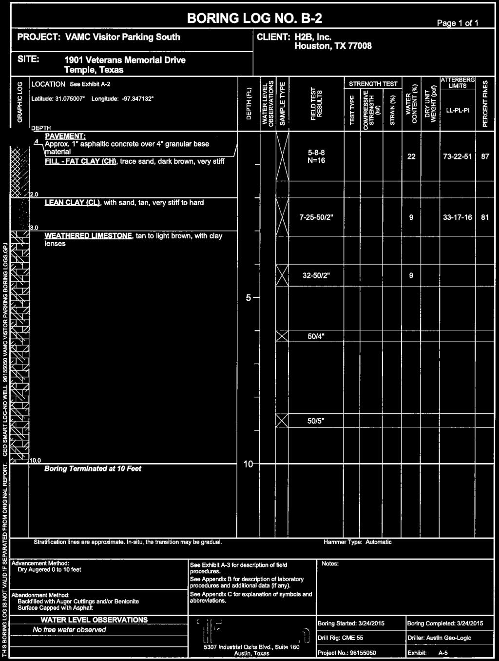
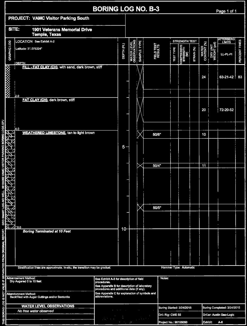
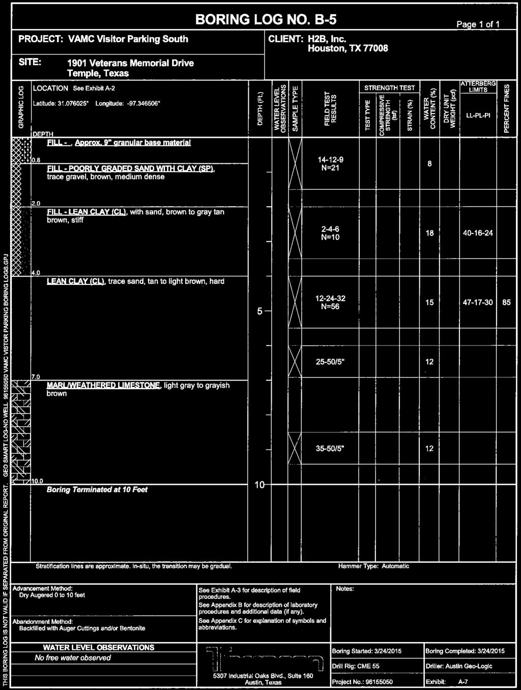
2 Geotechnical Engineering Letter Report VAMC Bldg 202 Domiciliary C-D Entryway Temple, Texas October 4, 2017 Terracon Project No Project Description Item Site layout Proposed Improvements Construction Finished Floor Elevation, FFE Maximum Loads Grading Below-Grade Areas Description See Exhibit A-2, Boring Location Plan. The project will include the construction of a new entryway on the north side of Domiciliaries C and D. Light-frame system planned to be supported on 4 drilled piers. Unknown; assumed to be within 1 foot of the existing grades. Dead Load: 7 kips Live Load: 5 kips Uplift Load due to Wind: 8 kips Unknown; assumed cuts and fills of less than 1 foot. None anticipated. SUBSURFACE CONDITIONS As mentioned previously, four projects were drilled within the campus. The boring logs from these projects are attached to this letter report. The subsurface conditions typically consisted of dark brown to brown fat clays over tan lean clays over limestone. Fill soils (as deep as 18 feet in Terracon Project No ) were encountered in some of the borings. The closest borings drilled to the current project from Terracon Project No encountered marl/weathered limestone at depths of about 3 to 7 feet. However, these borings were terminated at depths of 10 feet. Other projects drilled in the campus indicate that limestone was encountered at depths ranging from about 8 to 23 feet. Therefore, the depths to limestone can vary widely across the site. RECOMMENDATIONS FOR DESIGN AND CONSTRUCTION The following recommendations are based upon the data obtained in our field and laboratory programs from the nearby projects, project information provided to us, and on our experience with similar subsurface and site conditions. 3.1 Foundation System Based upon the subsurface conditions observed during previous explorations in the campus, a drilled pier foundation system bearing into the tan to light brown lean clay soils would be appropriate to support the proposed entryway. As an alternative, a drilled pier foundation system bearing into the limestone would also be appropriate to support the proposed entryway. Recommendations for these types of foundation system are provided below. Responsive Resourceful Reliable 2
3 Geotechnical Engineering Letter Report VAMC Bldg 202 Domiciliary C-D Entryway Temple, Texas October 4, 2017 Terracon Project No Drilled Pier Foundation System in Tan to Light Brown Lean Clay Soils Minimum depth 1 Description Bearing Pressures (allowable) 2 Side Friction (net allowable) (Compression/ Tension) Straight-Sided Drilled Pier Design Parameter 15 feet FFE Net dead plus sustained live load 4,000 psf Net total load 6,000 psf 0 8 feet deep None 8 feet and below 500 psf/400 psf Estimated uplift force 4,5,6 35*D Minimum percentage of steel Approximate total settlement 7,8 Estimated differential settlement 7,8 1. To bear within the tan to light brown to brown soils. 2. Whichever condition yields a larger bearing area. 0.5 percent 1 inch Approximately ½ to ¾ of total settlement 3. For the evaluation of transient (temporary/short term) loading such as wind loads, the above design parameters can be increased by 33 percent, as per IBC Section The amount of reinforcing steel required can be computed by assuming that the dead load of the structure surcharges the pier, that the above estimated tensile force acts vertically on the shaft, and that the minimum pier depth is sufficient in withstanding the uplift on the pier itself. The amount of required steel, as calculated by the structural engineer, should extend the entire pier length and in no case should the percentage of steel be less than 0.5 percent. 5. Uplift force (in kips) is used to calculate pier reinforcing steel. The term D is the pier diameter in feet. The equation for uplift force includes a factor of safety 6. The recommended minimum embedment depth of the piers should be sufficient in withstanding soil uplift forces. Please note that the uplift force equation given above is intended for calculating the required reinforcing steel and is not intended for calculating required pier embedment to overcome soil uplift forces. Additional reinforcing steel may be needed to resist external structural uplift forces. 7. Provided proper construction practices are followed. For adjacent piers, we recommend a minimum edgeto-edge spacing of at least 2 pier diameters (or 3 pier diameters center-to-center) based on the larger diameter of the two adjacent piers. In locations where this minimum spacing criterion cannot be accomplished, Terracon should be contacted to evaluate the locations on a case-by-case basis. 8. Will result from variances in subsurface conditions, loading conditions and construction procedures, such as cleanliness of the bearing area or flowing water in the shaft. Please note that the Austin Group limestone was encountered at variable depths of about 3 to 23 feet below existing grades in the prior 4 projects on the VAMC. Therefore, the limestone may be shallower than 15 feet. In this scenario, we recommend that the piers be embedded at least 2 feet into the limestone as recommended below. Responsive Resourceful Reliable 3
4 Geotechnical Engineering Letter Report VAMC Bldg 202 Domiciliary C-D Entryway Temple, Texas October 4, 2017 Terracon Project No Drilled Pier Foundation System in Limestone Principal column and wall loads for the proposed entryway may be supported on drilled straightsided piers embedded at least 2 feet into the tan to light brown to light gray Austin Group limestone. Although the variable quality/strength of the limestone is taken into account in our design parameters, piers should not be terminated on a soft clay layer or zone within the bedrock. At locations where the design embedment results in the pier terminating on a softer layer, the pier should be extended to bear upon more competent limestone. Due to the fact that exact depth to limestone is unknown for this entryway, the contract documents should include unit rates for additional drilled pier footage at various pier diameters. In addition, the construction budget for this project should include overages due to the likelihood of additional costs associated with extending the drilled piers to greater depths. Description Minimum embedment into bearing stratum 1 Minimum pier diameter Bearing pressure (net allowable) Side Friction (net allowable) Compression Tension Drilled Pier Design Parameter 2 feet 18 inches 20,000 psf 2,000 psf for pier portions embedded beyond the 2 foot embedment depth Estimated uplift force 2,3,4 35*D Minimum percentage of steel Approximate total settlement 5 Estimated differential settlement 6 1. To bear within the Austin Chalk limestone. 1,600 psf for pier portions embedded beyond the 2 foot embedment depth 0.5 percent ¾ inch maximum Approximately ½ to ¾ of total settlement 2. The amount of reinforcing steel required can be computed by assuming that the dead load of the structure surcharges the pier, that the above estimated tensile force acts vertically on the shaft, and that the minimum pier embedment is sufficient in withstanding the uplift on the pier itself. The amount of required steel, as calculated by the structural engineer, should extend the entire pier length and in no case should the percentage of steel be less than 0.5 percent. 3. Uplift force (in kips) is used to calculate pier reinforcing steel. The term D is the pier diameter in feet. The equation for uplift force includes a factor of safety 4. The recommended minimum embedment depth of the piers should be sufficient in withstanding soil uplift forces. Please note that the uplift force equation given above is intended for calculating the required reinforcing steel and is not intended for calculating required pier embedment to overcome soil uplift forces. Additional reinforcing steel may be needed to resist external structural uplift forces. Responsive Resourceful Reliable 4
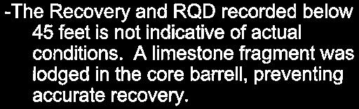
5 Geotechnical Engineering Letter Report VAMC Bldg 202 Domiciliary C-D Entryway Temple, Texas October 4, 2017 Terracon Project No Provided proper construction practices are followed. For adjacent piers, we recommend a minimum edge-to-edge spacing of at least 1 pier diameter (or 2 pier diameters center-to-center) based on the larger diameter of the two adjacent piers. In locations where this minimum spacing criterion cannot be accomplished, Terracon should be contacted to evaluate the locations on a case-bycase basis. 6. Will result from variances in subsurface conditions, loading conditions and construction procedures, such as cleanliness of the bearing area or flowing water in the shaft. 3.4 Foundation Construction Considerations Drilled pier foundations should be augered and constructed in a continuous manner. Concrete should be placed in the pier excavations following drilling and evaluation for proper bearing stratum, embedment, and cleanliness. The piers should not be allowed to remain open overnight before concrete placement. Surface runoff or groundwater seepage accumulating in the excavation should be pumped out and the condition of the bearing surface should be evaluated immediately prior to placing concrete. The drilling equipment utilized should be readily capable of excavating the Austin Group limestone observed at this site. Drilling equipment with insufficient torque and/or augers/bits/core barrels that are not suited for variable and/or hard rock conditions will likely result in poor production rates. On any construction site, there is a possibility for zones of groundwater inflow and/or sloughing soils. Therefore provisions must be incorporated into the plans and specifications to utilize casing to control sloughing and/or groundwater seepage, if any occurs during pier construction. Removal of the casing should be performed with extreme care and under proper supervision to minimize mixing of the surrounding soil and water with the fresh concrete. If water infiltration becomes excessive, slurry drilling techniques (or other drilling means) could be necessary. Concrete should exhibit slump as stated in the Structural Engineer s specifications. Under no circumstances should loose soil be placed in the space between the casing and the pier sidewalls. The concrete should be placed using a rigid tremie or by the free-fall method provided the concrete falls to its final position through air without striking the sides of the hole, the reinforcing steel cage or any other obstruction. A drop chute should be used for this free-fall method. The use of casing should help to minimize groundwater inflow into the pier excavation. If seepage persists even after casing installation, the water should be pumped out of the excavation immediately prior to placing concrete. If groundwater inflow is too severe to be controlled by pumping, the concrete should be tremied to the full depth of the excavation to effectively displace the water. In this case, a clean-out bucket should be utilized to remove loose soil and/or rock fragments from the pier bottom before placing steel and concrete. Responsive Resourceful Reliable 5
6 Geotechnical Engineering Letter Report VAMC Bldg 202 Domiciliary C-D Entryway Temple, Texas October 4, 2017 Terracon Project No GENERAL COMMENTS Terracon should be retained to review the final design plans and specifications so comments can be made regarding interpretation and implementation of our geotechnical recommendations in the design and specifications. Terracon also should be retained to provide testing and observation during foundation installation and other construction phases of the project. The analysis and recommendations presented in this report are based upon the data obtained from the borings performed at the indicated locations from previous years. This report does not reflect variations that may occur across the VAMC site, or due to the modifying effects of weather. The nature and extent of such variations may not become evident until during or after construction. If variations appear, we should be immediately notified so that further evaluation and supplemental recommendations can be provided. The scope of services for this project does not include, either specifically or by implication, any environmental or biological (e.g., mold, fungi, bacteria) assessment of the site or identification or prevention of pollutants, hazardous materials, or conditions. If the owner is concerned about the potential for such contamination or pollution, other studies should be undertaken. For any excavation construction activities at this site, all Occupational Safety and Health Administration (OSHA) guidelines and directives should be followed by the Contractor during construction to provide a safe working environment. In regards to worker safety, OSHA Safety and Health Standards require the protection of workers from excavation instability in trench situations. This report has been prepared for the exclusive use of our client for specific application to the project discussed and has been prepared in accordance with generally accepted geotechnical engineering practices. No warranties, either express or implied, are intended or made. Site safety, excavation support, and dewatering requirements are the responsibility of others. In the event that changes in the nature, design, or location of the project as outlined in this report are planned, the conclusions and recommendations contained in this report shall not be considered valid unless Terracon reviews the changes and either verifies or modifies the conclusions of this report in writing. Responsive Resourceful Reliable 6


7


8 PROJECT SITE DIAGRAM IS FOR GENERAL LOCATION ONLY, AND IS NOT INTENDED FOR CONSTRUCTION PURPOSES Project Mgr: AM Drawn By: AM Checked By: BSM Approved By: BSM Project No Scale: N.T.S File Name: SITE PLAN Date: 10/4/ Industrial Oaks Blvd, Suite 160, Austin, Texas PH. {512} FAX. {512} SITE AERIAL AND LOCATION PLAN VAMC Bldg 202 Domiciliary C-D Entryway Teague Place Temple, Texas EXHIBIT A-1

9 B-3 B-4 B-1 B-2 B-5 B-6 B-1 B-2 B-4 B-3 B-1 B-2 B-5 B-4 B-3 B-2 B-1 Boring Locations from Boring Locations from Boring Locations from DIAGRAM IS FOR GENERAL LOCATION ONLY, AND IS NOT INTENDED FOR CONSTRUCTION PURPOSES Boring Locations from Project Mgr: AM Drawn By: AM Checked By: BSM Approved By: BSM Project No Scale: N.T.S File Name: SITE PLAN Date: 10/2/ Industrial Oaks Blvd, Suite 160, Austin, Texas PH. {512} FAX. {512} BORING LOCATION PLAN VAMC Bldg 202 Domiciliary C-D Entryway Teague Place Temple, Texas EXHIBIT A-2
10
11
12
13

14
15
16
17

18
19

20
21

22
23

24
25

26
27
28
29

30
31