A (mm) B (mm) A (mm) B (mm) 5lt X lt x lt x 8. 5lt x ft extension. 8ft extension ft extension 3100
|
|
|
- Clare Horn
- 5 years ago
- Views:
Transcription
 5lt X 6 1990 6ft extension 1860 5lt x 8")

1 NOMINAL SIZE A (mm) B (mm) NOMINAL SIZE A (mm) B (mm) 5lt X ft extension lt x lt x lt x ft extension ft extension ft extension

; part lists, B-base,")
2 Thank you for purchasing your new Robinsons greenhouse. We recommend you familiarise yourself with the instructions and read all safety information before you commence assembly. This instruction manual is also available online at in our technical help section should you need to reprint it. Should you require any additional advice you can always call us on These instructions are divided into sections highlighted by a white number/letter on a black background at the bottom corner of most pages (see opposite page for details); part lists, B-base, P-preparation, 1-side, 2-front gable, 3-rear, 4-joining the three sides together, 5-roof, 6-wall attachment, 7-vent, 8- door, 9-glazing, 10-vent attachment, 11-door attachment, 12-anchoring down, 13-optional louvre, 14-optional shelf, 15-optional staging, 16-finishing touches. If you need to contact us for assistance please refer to the relevant section/s. If your building is longer than 12, i.e. has an extension then please also refer the separate extension manual. Safety Warning Glass and aluminium can potentially cause injury. Please ensure you wear protective goggles, gloves, headgear and suitable footwear when assembling and glazing the building. Please remember that glass is fragile and should be handled with extreme care. Always clear up and dispose of any breakages immediately. Do not assemble the greenhouse in high winds. For safety reasons and ease of assembly, we recommend that this greenhouse is assembled by a minimum of two people. Please clear all lying snow from the greenhouse roof as it can cause the roof to buckle or collapse. Site Preparation When selecting a site for your greenhouse, it is vital that you choose as flat and level an area as possible. A concrete or slabbed base will provide the most solid foundation for your greenhouse. IMPORTANT: Do not fix your building down until the building is fully assembled, including glazing. Avoid placing your greenhouse under trees or in other vulnerable locations. To minimise the risk of wind damage, try to select as sheltered a site as possible, e.g. beside a hedgerow or garden fence. Additional Considerations Please bear in mind that assembling your greenhouse can be time consuming. You may need to spread the construction over two or more days. We recommend that you avoid leaving the building partially glazed. If you ever have to leave your greenhouse half assembled and not anchored down, weigh it down with slabs or bags of sand to stop the wind moving it. You will find it helpful to prepare a large, clean and clear area in which to work in. A garage floor or flat lawn area is ideal. If you have arranged for someone to install your greenhouse for you, please check that all components are included. Some parts are numbered and can be identified by a stamped or hand written number (without the D ). Alternatively, the components can be identified by their distinctive profiles, lengths and quantities detailed in the parts list (see next page). Anchoring down your greenhouse should be the final stage of construction (including glazing). Once installed your greenhouse requires little maintenance, but to maintain the smooth running of your door(s) WD40 or similar can be applied to the door wheels and lower door guides. Guarantee Your new Robinsons greenhouse is guaranteed for 10 years against faulty manufacture of the framework. This does not include glazing, moving parts, accidental damage or wind damage. KEY SYMBOL KEY DESCRIPTION EXTERNAL VIEW INTERNAL VIEW THINK THIS SECTION RELATES TO ANOTHER (e.g. 1 to 5) CORRECT 639mm D866 DO NOT FIX DOWN! TWIST TO LOCK TIGHTEN PUSH AND HOLD CUT TO LENGTH 2
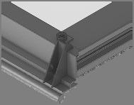
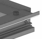
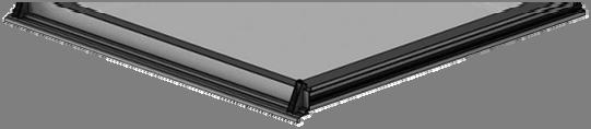
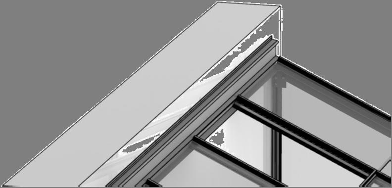
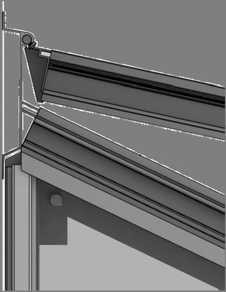
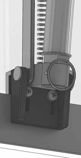
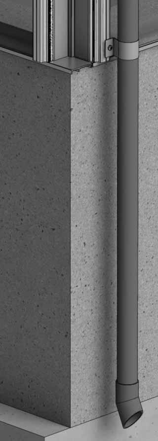
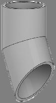
3 SECTION No TITLE ASSEMBLY SYNOPSIS: IMPORTANT INFORMATION / CONSIDERATIONS B P PARTS LIST BASE PREPARATION 1 SIDE a 7b 8 FRONT REAR JOINING THE THREE SIDES ROOF VENT VENT SLAM DOOR 9 GLAZING 10 VENT ATTACHMENT DOOR ATTACHMENT ANCHORING DOWN OPTIONAL LOUVRE 14 OPTIONAL SHELVING 15 OPTIONAL STAGING 16 REAR WALL ATTACHMENT FINISHING TOUCHES Most components should have a D code punched into their metal surface. Identify and separate all like for like components prior to assembly. The parts list also separates parts into the various sections shown below. Parts can also be identified by their profile pictures and stated lengths etc.. Base dimensions and recommendations. Ensure that your base is level as this will make assembly of the building, especially the glazing of the roof much more straight forward. Tools required. IMPORTANT: Use WD40 or similar in the glazing bar channels and insert the black glazing rubber prior to frame assembly. Take the side glazing bars D609 with the rubber inserted and the diagonal braces D604, use bolts to join them to the gutter and bolts to the cills (note how the head of the bolts slide into each glazing bar during construction). Again ensuring that the gable framework is rubbered-up follow the diagrams to assemble each end of the building. Make sure that you have inserted the extra bolts utilised in sections 4, 5 and 11. On the roof and side corner bars not every rubber channel will require rubber unless it is to be utilised in a partition (see separate manual and section P). Take the side (1) and both gables (2 & 3) and join them together on your base. It is a good idea to tie some ladders to the side to support them if you do not have anyone to hold them for you. Attach the ridge and then the rubbered-up roof bars ensuring that they are fully butted up to the ridge and down onto the gutter. Some tubular braces are supplied to add extra strength, they can be fitted now or later with crop head bolts. The main body of the frame is complete it can be attached to the wall. Make sure that the wall bars are vertical and the ridge is horizontal then drill and screw the building to the wall. Do not attach the base to the ground until section (12) as your building may not be square. Once the vent is glazed add silicone to the vent sides and top. Stand the vent/s on their hinge (vent top) and then leave the silicone to set. The slam bar D079 can be moved up and down between the roof glazing bars so that it can be butted down onto the pane of glass beneath, the autovent is attached to it later on (10). Construct the door using the diagrams and then leave to one side ready for attachment in section (11). Layout the bar capping and covers around the building like a sundial checking that all is present and correct. You can also place the roof capping in the gutters so they are closer to hand. The glass in the ends has to bevel on the black separator strip, this bevelling action allows the glass to tuck underneath the roof corner canopy. Use the capping and the self tapping screws to then hold the glass in place. The covers then enclose the screw heads giving a neat finish. A top tip is to not attach the door post capping (D814/D836) until you have fitted the door runner and threshold (11) to give you more room to manoeuvre. Take the assembled vent and slide the vent hinge D866 into the end of the ridge allowing the vent the pivot open and closed. Vent stops go either side of the vent to stop any lateral movement (so insert stop / vent / stop). Attachment of the Bayliss XL autovents. Use the bolts inserted in section (2) to attach the upper door track. The lower door runner D860 and ramp threshold D087 push down and lock together. Now that the greenhouse is finished and the door and vent/s are operating without interference then you need to anchor the building down using 2 rawl plugs and screws. Use a 7mm masonry bit in a hammer drill to create the holes. They attach to the building during the glazing process (9) like a piece of glass with a black separator above and below them. Robinsons integral cantilever staging and shelving attaches to the inside of the greenhouse frame using either square head bolts (insert four into each side glazing bar D609 during construction of the sides (1)) or rectangular crop head bolts which can be fitted retrospectively (both sets of bolts accompany the shelving/staging). This system allows the height of either the staging or the shelf to be set at an operator specific height. Commonly the staging brackets are set 900mm from the cills though you can alter this to suit the end user/s. The aluminium shelf / staging slats come in two lengths; (4 ):1240mm D2002 and (6 ):1860mm D2003. These slats can combine to create any length of staging required, i.e = 10 etc... Now that the main body of the structure is complete you can add; downpipe fittings, eave bungs. 3
 5lt 6 5lt 8")


")


4 Section Ref Part No. Section Size (mm) 5lt 6 5lt 8 5lt 10 5lt 12 Section Ref Part No. Section Size (mm) 5lt 6 5lt 8 5lt 10 5lt 12 D D D D D D D D D D RUBBER 1000 (1m) D854L 1744 D854R 1 RUBBER D174 D D D D (1m) 31 N/A 8 D174 N/A D D039L 1? D039R ? D668 1? D ? RUBBER 1000 (1m) D D D D863L D D863R D D D D D079 PLUS FLUFF D D114 N/A D D220 PLUS FS6060 SCREW N/A D D149 N/A 2 4 D205 N/A
 5lt 6 5lt 8 5lt 10 5lt 12 D090 + D347 lock = D301 1824 1 D094 1824 1 D096 + D217 wheel = D307 611 1 D095 611 1 D097 611 1 D232 905 2 D233 797 2 P053 N/A 1 1 D618 1144 2 3 4 5 2/3")

5 Section Ref Part No. Section Size (mm) 5lt 6 5lt 8 5lt 10 5lt 12 Section Ref Part No. Section Size (mm) 5lt 6 5lt 8 5lt 10 5lt 12 D090 + D347 lock = D D D096 + D217 wheel = D D D D D P053 N/A 1 1 D /3 D D D D D D D /3 D D D D D /3 D D /3 D D D D D D D D D840B D D MAIN FRAME QUANTITIES VENTS / DOORS etc SEPERATE m D D D D D D154 N/A 1 5
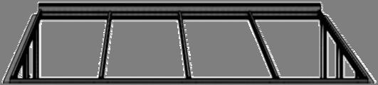
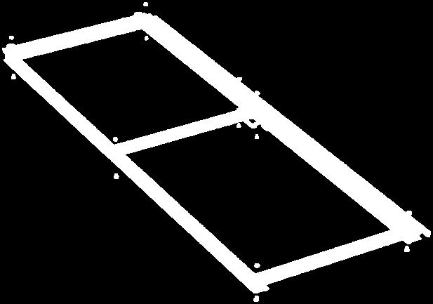
6 50mm MINIMUM GUIDANCE NOTE FOR ROBINSONS DWARF WALL GREENHOUSES. FOOTINGS CONCRETE STRIP FOOTINGS SHOULD BE A MINIMUM OF 400mm WIDE X 200mm DEEP. IF THE SITE IS ON MADE UP GROUND IT IS IMPORTANT THAT THE FOOTINGS ARE CUT INTO THE COMPACTED GROUND BELOW. WHERE THE GROUND IS LIABLE TO MOVEMENT SUCH AS HEAVY CLAY OR LOOSE SANDY SOIL REINFORCING SHOULD BE ADDED TO THE CONCRETE FOOTINGS. WALLS IT IS MOST IMPORTANT THAT THE BRICKWORK IS IN ACCORDANCE WITH THE DIMENSIONS PROVIDED AND IS SQUARE, LEVEL AND UPRIGHT, THE DIAGONAL MEASUREMENTS SHOULD BE EQUAL. WALLS CAN BE EITHER DOUBLE OR SINGLE SKIN. THE TOP COURSE OF BRICKS SHOULD BE LAID FROG DOWN. IF ENGINEERING BRICKS ARE USED FOR THE TOP COURSE PLEASE ENSURE THEY ARE SOLID NOT CELLULAR (WITH HOLES THROUGH THEM) OR FIXING DOWN OF THE GREENHOUSE WILL BE A PROBLEM. BRICKS SHOULD BE A GOOD QUALITY STOCK BRICK, SAND FACED FLETTON TYPE BRICKS ARE NOT SUITABLE. GABLE DOOR OPENING THE DOOR THRESHOLD REQUIRES BRICK WORK ACROSS THE OPENING WHICH SHOULD BE LEVEL WITH THE FINISHED FLOOR LEVEL (F.F.L) OF THE GREENHOUSE. THE OPENING FOR THE DOORWAY AND THE HEIGHT TO THE TOP OF THE WALL FROM THE THRESHOLD LEVEL REQUIRE THE HIGHEST ACCURACY AND ARE MOST IMPORTANT SO THAT THE DOOR FITS THE APERTURE CORRECTLY. IT IS ADVISABLE TO MAKE A WOODEN TEMPLATE TO CHECK THE DOOR APERTURE DIMs. IF SINGLE SKIN WALLS ARE USED THEN PIERS SHOULD BE FORMED AT THE DOOR OPENING. IN ORDER TO SUPPORT THE OUTER EDGE OF THE DOOR THRESHOLD THERE MUST BE A PROJECTION OF BRICKWORK / CONCRETE INFRONT OF THE DOOR END WALLWITH A MINIMUM WIDTH OF 50mm. THIS NEEDS TO BE LEVEL WITH THE DOOR THRESHOLD OPENING. Property of 'Robinsons Greenhouses' TITLE: 5LT DWARF WALL PLAN 600mm 655mm DOOR OVERALL LENGTH 'L' 1620mm OVERALL WIDTH MIRROR LINE FOR DOOR AT OTHER END 965mm SINGLE BRICK SKIN OPTION WITH PIER DOUBLE BRICK SKIN OPTION OVER ALL LENGTH 'L' = BASIC GREENHOUSE LENGTH + EXTENSION IF REQUIRED BASIC GREENHOUSE LENGTH GREENHOUSE EXTENSION LENGTH 6ft LONG 1990mm 6ft EXT LONG 1860mm 8ft LONG 26 8ft EXT LONG 2480mm 10ft LONG 3230mm 10ft EXT LONG 3100mm 12ft LONG 3850mm 12ft EXT LONG 3720mm


7 Feed glazing rubber into each glazing bar and trim to length. Notice that some channels are only used on a partition. Applying a lubricant to the aluminium channels will speed up insertion. The frame is assembled by feeding square headed bolts, either or in length into the slots on glazing bars and then locating those bolts through holes in purlings and cills, etc Twist in (rectangular) crop headed bolts are also used towards the end of construction to attach components to the frame when the glazing bar slots are no longer exposed at the ends. 7


8 6 X 1 D042 D043 6 X 1 DWARF Part No mm Quantity D D D D D174 2 M6-2 M6-4 M6-6 NUT Rubber X 1 DWARF Part No mm Quantity D X 1 D014 D021 D D D D174 2 M6-3 M6-5 M6-8 NUT Rubber X 1 DWARF Part No mm Quantity D X 1 D015 D022 D D D D174 4 M6-4 M6-6 M6-10 NUT Rubber X 1 D X 1 DWARF Part No mm Quantity D D D D D174 4 M6-5 M6-7 8 D023 M6-12 NUT Rubber


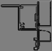
9 D604 D609 TRANSIT BOLT ON DIAGONALS D609 D604 9


10 Part No mm Quantity D D D D DOOR ON LEFT EXTERNAL VIEW Part No mm Quantity D149 1 D174 3 D227 17m DOOR ON RIGHT EXTERNAL VIEW Part No mm Quantity D D D D D D D M6X10 9 M6X15 11 D D D D854R M6NUT 20 D854L D854R + D854L D657 D670 D670 D657 D608 D626 DOOR ON LEFT DOOR ON RIGHT D626 D608 D675 D675 D669 D668 D628 D628 10


11 D854R / D854L D854R / D854L D854R / D854L D670 D149 D675 D608 D626 D608 D174 D675 D670 D670 D626 D628 D669 / D668 11


12 Part No mm Quantity D039L D D D DOOR ON LEFT EXTERNAL VIEW Part No mm Quantity D149 1 D174 2 D227 14m DOOR ON RIGHT EXTERNAL VIEW Part No mm Quantity D039R D D D D D D M6X10 7 M6X15 11 D D D D854L M6NUT 18 D854R D854L D854R D110 D110 D657 D657 D655 D656 D626 D608 D608 D626 D656 D655 D039L D039R 12


13 D854R / D854L D854R / D854L D854R / D854L D110 D149 D656 D626 D608 D656 D110 D656 D608 D655 D626 D174 D039L / D039R D039L / D039R D039L / D039R 13


14 14 EQUAL


15 Part No mm Quantity Part No mm Quantity Part No mm Quantity Part No mm Quantity D D D D D D D D D D D D RUBBER RUBBER RUBBER RUBBER D065 D065 2 D609 D126 X2 15


16 D234 D234 EQUAL 16

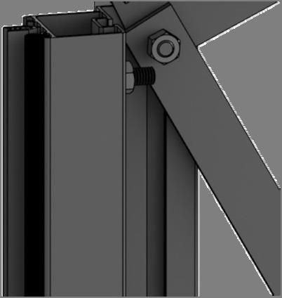
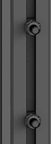
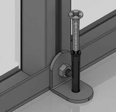
 Drill through the vertical wall bars with a 7mm drill/hammer drill using a")
 Drill through the vertical wall bars with a 7mm drill bit and enlarge the")

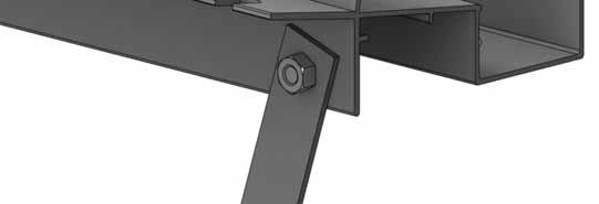
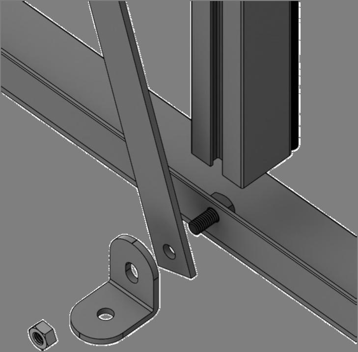
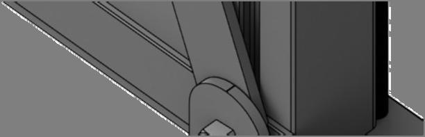
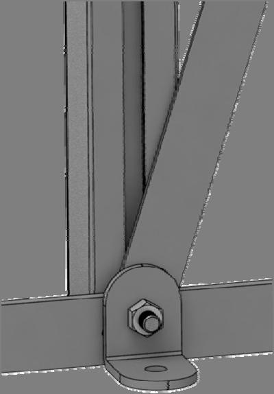
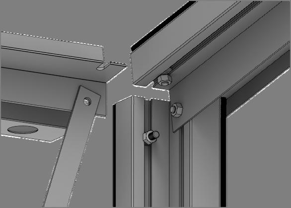
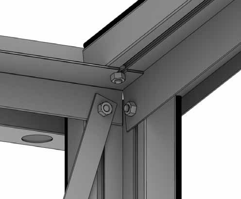
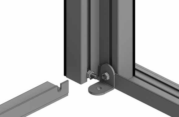
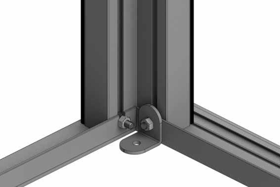
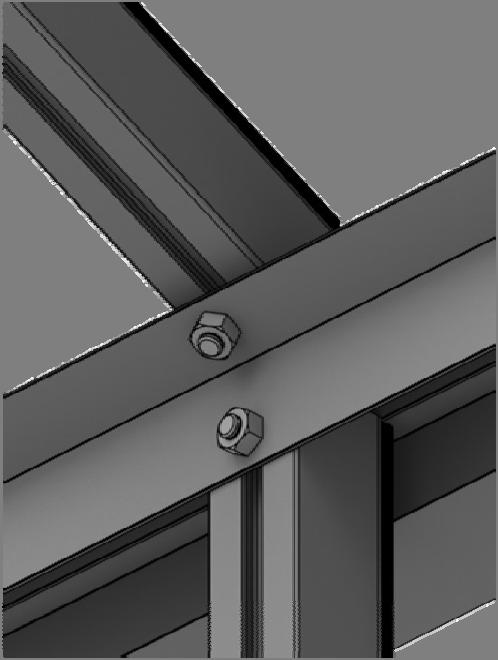
17 5x6 5x8 5x10 5x12 Part No mm Quantity SYSCR SYRAWL SILICONE D119 7mm No 10 x 3 There are various methods for attaching your greenhouse frame to its wall. 1) Drill through the vertical wall bars with a 7mm drill/hammer drill using a 7mm masonry bit, Use 3 screws to secure the wall bars. 2) Drill through the vertical wall bars with a 7mm drill bit and enlarge the inner hole to. Use 2 screws to secure the wall bars hiding the screw heads inside the bars to give a neat finish. 3) Use L-shaped brackets and 2 screws to secure the frame to the wall similar to anchoring the greenhouse down (e.g. section 12). 17


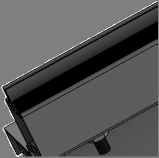
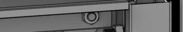
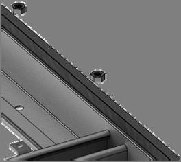
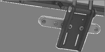
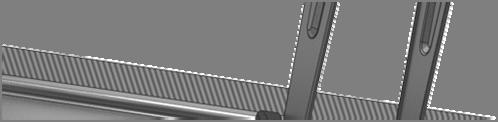
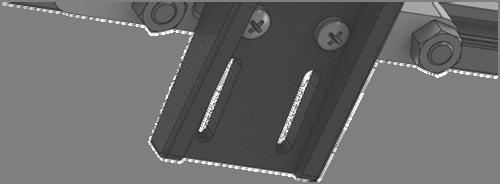
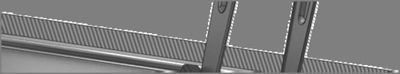
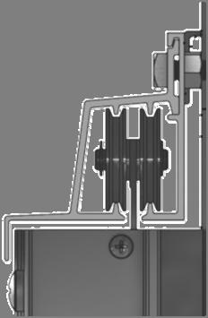
18 Part No mm Quantity D Part No D220 PLUS FS6060 SCREW mm Quantity N/A 2 D863L D205 N/A 2 D of x 610 pane D863R D SY- BOLM6X SYNUTM6 M6 4 8 X 12 S/T FS x 19 S/T FS D863R 2 D863R D866 D863L D866 D of x 610 pane 18


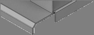


19 2 2 D862 D863L D862 2 FLIP VIEW 2 2 CUT 6mm SILICONE D119 19


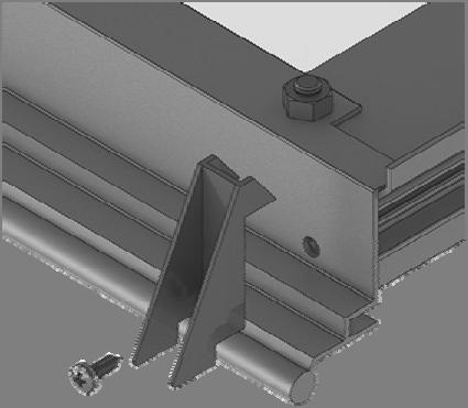
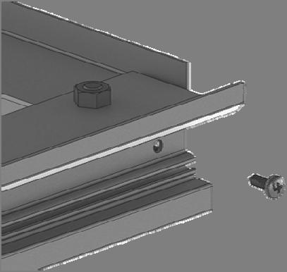
20 Part No SY- BOLM6X11 SY- BOLM6X15 SYBOLM6 X11CROP mm Quantity SYNUTM6 N/A 4 Part No mm Quantity D079 PLUS FLUFF D114 N/A 2 D114 D079 D114 FLIP VIEW 20


21 D1208 GLASS D1216 GLASS D1216 GLASS 21


22 D x 812 pane Part No mm Q Part No mm Q D090 + D347 lock = D D D D P053 N/A 1 D x 922 pane D096 + D217 wheel = D D D D D840B 4000 D263 PACK. 1 N/A 7 N/A 7 D260 PACK N/A 12 4 D095 D301 D095 D094 A D233 A D233 B B B D232 33mm D232 22


23 D x 812 pane C D x 922 pane D232 D x 922 pane C E E D307 8 D097 D225 F D225 F 7 H D840B 7 D840B G D840B P053 H 23 G
 D618")


24 PART No Section Size (mm) D D D D D D D D D D D D D D D D D D D D D D D811 D871 D877 D666 D662 D836 D814 D811 D870 D836 D814 D811 D870 D667 D660 D663 D614 D658 D610 D811 D870 D876 D876 D876 D811 D871 D877 D619 D620 D619 D618 D619 D618 D619 D618 D619 D620 D614 D663 D664 D665 D610 D658 D659 D661 24

 8 10 12 M D1216 S 610")


25 ROOF PANES OVERLAP A A A A H K S S S S P C S N S S S S D P K J N S S PART No Size (mm) M D1216 S 610 X D1208 A 610 X D625 N 305 X D911 C 555 X L D912 D 555 X D902 P ANGLE 2 D624 M 610 X D901 K ANGLE 2 D729 D101 / ROSEPS L 525X long 1 D907 J ANGLE 1 D622 H ANGLE 1 D222/W P 15 D101 / ROSEPS 610 long (inc cuts to 305mm) K 165 J H


26 D220 D220 26


27 D862 D079 27


28 Part No mm Q D Part No mm Q D D845 2 D SY- BOLM6X15 10 SYNUTM6 10 D D845 D845 D836 D670 D814 D163 D675 D670 D845 28


29 15 4 N/A 4 D084 D083 D N/A 4 D163 D675 D864 D670 D845 29


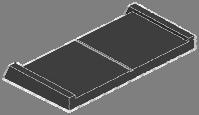
30 Part No Quantity D860 1 D087 1 D087 D860 D860 D087 30


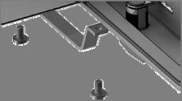
31 Part No Quantity D842 1 SYBOLM6 X11CROP 2 Part No Quantity FS D312 2 D204L /B D204R /B 1 1 O4mm through metal only FS6018 FS6018 D204R D312 31


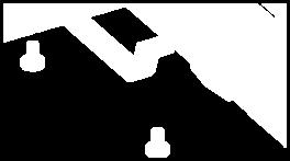
32 O7mm 32


")


33 Part No mm Quantity D168L D168R (handle) D D FS D166 D166 D168L D168R D165 D165 INTERNAL VIEW D729TG x 525 panes x 6 PINCH ALL GLASS RETAINERS BEFORE GLAZING 33 D165


34 Example: 2x 4 3 slat shelves ST0304 = 8 run crop D2013 D609 D608 D608 D2014 crop D2002 =1240mm D2002 =1240mm D2014 D2021 D2003 =1860mm 34


35 Example: 2x 4 7 slat staging ST0704 = 8 run D608 D609 D2045 D2043 D608 D2044 crop crop D2046 D2046 D2047 D2044 D2045 D2043 D2042 D2042 D2042 D2002 =1240mm FINISH D2002 =1240mm START D2003 =1860mm D2002 =1240mm 35


36 Example: 2x 4 10 slat staging ST01004 = 8 run D608 D174 D174 D608 D2045 D2043 D2051 D609 D2044 D2052 crop crop D2048 D2043 D2049 D2048 D2045 D2044 D2050 D2050 D2050 D2002 =1240mm START FINISH D2002 =1240mm D2052 D2003 =1860mm D2002 =1240mm 36


37 SILICONE D214 D119 SILICONE D119 D201 CUT D203 CUT D208 D608 D608 D202 D211 D841 SILICONE D119 D211 D207 D206 D608 37

38 38

39 39
40 Please be aware that this is a multi-national manual, if you spot any errors or have any constructive comments regarding the manual please james.spooner@greenhousepeople.co.uk and I will make the necessary amendments. Whilst the information contained in this booklet is accurate at the time of publication, changes in the course of Robinsons policy of improvement through development and design might not be indicated. We point out this fact to avoid any infringements of the Trade Descriptions Act and also to advise that Robinsons Greenhouses reserve the right to change specifications and materials without prior notice. In addition any photographs of completed buildings would be most appreciated to add to our portfolio. THIS GREENHOUSE BOX WAS PACKED BY: DATE: To contact Robinsons Customer Services us at sales@robinsonsgreenhouses.co.uk or call us on Our address is Robinsons Greenhouses, Unit 19 Blythe Park, Cresswell, Stoke-on-Trent, Staffordshire, ST11 9RD 40