Geo-E2010 Advanced Soil Mechanics L Wojciech Sołowski. 19 March 2017
|
|
|
- Roland Fletcher
- 5 years ago
- Views:
Transcription
1 Geo-E2010 Advanced Soil Mechanics L Wojciech Sołowski 19 March 2017
2 Slope stability: review
3 Q: Shortcomings of undrained cohesion You wrote that the shortcoming is that the analysis is short term Well the real problem is the value of undrained cohesion - the value of the undrained cohesion depends on the rate of shear - additionally: - usually increases with depth (even in the same soil layer) due to higher consolidation stress - natural non-uniformity of soil affects undrained cohesion Department of Civil Engineering Advanced Soil Mechanics. W. Sołowski 3
4 Q: Method of slices Problems related to why extra assumptions are needed Without extra assumptions we have too many unknowns in the equations to solve them all A B C D E F G H I L Equations 4n 2n n n Unknowns 1 n n n n-1 n-1 n-1 Condition force equilibrium in two directions for each slice moment equilibrium for each slice Mohr-Coulomb failure criterion total number of equations Description factor of safety normal force at the base of each slice, P i locationof normal forces at the base of slices shear force at the base of each slice, S i interslice horizontal force, E i interslice vertical force, T i location of interslice forces (line of thrust) h i 6n-2 total number of unknowns Department of Civil Engineering Advanced Soil Mechanics. W. Sołowski 4
5 Q: Tension crack We will talk more today: d = z c = 2cu γ Characteristic values! - but generally in cohesive soil tensile stress is present - as soils do not transmit tension, they will crack - crack can be filled with water - leading to extra forces Department of Civil Engineering Advanced Soil Mechanics. W. Sołowski 5
6 Retaining walls

7 Nicoll Highway, Singapore 4 deaths, 3 persons injured very significant cost reasons investigated in detail Department of Civil Engineering Advanced Soil Mechanics. W. Sołowski 7

8 Nicoll Highway, Singapore Department of Civil Engineering Advanced Soil Mechanics. W. Sołowski 8

9 Nicoll Highway, Singapore Department of Civil Engineering Advanced Soil Mechanics. W. Sołowski 9

10 Nicoll Highway, Singapore Reasons: lowering cost 1. FE analysis: the method was wrong the constructor knew it, but used it anyway, as led to more economical design problem: the method used drained shear strength when failure was in undrained conditions 2. Cost reduction at the construction site some temporary struts increasing strength were not in place 3. Poor monitoring of instruments: subcontractors were the cheapest and not familiar with the instruments and monitoring techniques. Abnormal trends were unnoticed because of incompetence Department of Civil Engineering Advanced Soil Mechanics. W. Sołowski 10
11 To learn Review: active & passive pressures, Rankine theory New limitations of Rankine theory Review: ultimate state, failure modes, calculations of standard retaining walls New some extra information Embedded walls: what they are, what types of embedded walls we have, how to construct them and when to used them Calculations for embedded sheet pile wall Braced excavations Extra slides: Coulomb wedge theory, now relatively rarely used. Extra materials: many worked examples (no EC 11 coefficients though)
12 Gravity Walls Consider four possible modes of failure for ultimate limit state: lateral sliding; overturning; slip failure and bearing capacity failure.
13
14 Reinforced Concrete Retaining Walls Modes of failure as for gravity walls, plus structural failure of the wall - calculate the maximum design bending moment in the wall (this occurs where the shear force is zero) and design the RC wall accordingly.
15

16 Other types of walls in the gravity wall category include e.g. gabion and crib walls.
17 Embedded Walls Flexibility of the wall may play a role! All modes of failure are possible with this type of wall, but bearing capacity failure is not likely (although vertical equilibrium should always be checked).
18 Examples of Embedded Walls Berlin method Sheet pile walls Contiguous pile wall Secant pile walls Diaphragm walls


19 Berlin Method (Vertical Soldiers and Horizontal Lagging)
20 Berlin Method (Vertical Soldiers and Horizontal Lagging) Method: Boreholes on the wall line, at 2 to 3 metre centres Place Steel I - section (soldiers) vertically in the holes Concrete soldiers in place below formation level As excavation proceeds install timber or precast concrete planks between soldiers. Soldiers can be anchored if required. Alternatively horizontal steel wailings are installed and anchors drilled at intervals along the length. Suitability: As a temporary soil support prior to construction of the permanent wall Use in dry ground, or where soil is self supporting prior to installation of each section of lagging Dewatering in moderately permeable soils is feasible to ensure soils remain in place during wall construction.
21 Berlin Method (Vertical Soldiers and Horizontal Lagging) Limitations: Method can give rise to loss of ground during lagging installation, or soil movement due to poor lagging/soil contact Even with good workmanship significant subsidence can result Does not prevent water flow, except if dewatering is adopted Dependant on soil being self-supporting.


22 Sheet Piling
23 Sheet Piling Method Installation originally - driving, but environmental constraints on noise and vibration have seen the advent of hydraulic methods e.g. Giken system Can be used in cantilever, or restrained by props or anchors tied into horizontal walling The sheet pile section is often governed by drivability rather than working load conditions Suitability Although can be used in permanent wall, generally for temporary works. Can be used in clays and gravels. Dense gravels, and also weak rocks, would require pre-boring Effective water barrier Where ground movements are not critical can be extracted for re-use
24 Sheet Piling Limitations In an urban environment, generally limited to silent piling methods as restrictions placed on noise and vibration. Length of sheet piling, for purposes of transportation and handling, limited to around 25 to 28 metres. High lateral loads can lead to excessive movement due to flexible nature of sheets. Can be overcome by using, for instance, I sections in combination with sheets.

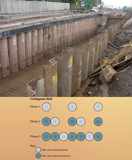
25 Contiguous Bored Piles
26 Contiguous Bored Piles Method Wall is made up of a line of unconnected piles. Typically pile centres are 75 to 100mm greater than the diameter of the installed piles. Greater use is being made of continuous flight auger (cfa) rigs, rather than rotary bored, to form the piles. Walls are tied together with capping beams, or concrete wailings, that can be incorporated into permanent works. Suitability Ease, and speed, of construction in most soil conditions. Although not a continuous wall ground water flows can be controlled by permeation or jet grouting Can form part of the permanent wall, with appropriate drainage and facing. Low level noise and vibration during installation.
27 Contiguous Bored Piles Limitations Verticality of piles, and thereby pile spacing and wall alignment, can be of concern Where cfa rigs are used piles will be limited to around 900mm diameter and 27 metres length Lateral connections e.g. capping beams, walling, slabs required to ensure piles act in unison Cannot control groundwater flows without additional works. Unsuitable for highly permeable soils.

28 Secant piles
29 Secant piles Methods Primary (female) piles are bored at centres slightly less than twice the pile diameter. Guide walls can be adopted to enhance alignment Before the female piles have achieved much of their strength secondary (male) piles are cutting into adjacent female piles It is usual to only reinforce the male piles, although in some instances all piles are reinforced often employing steel I-sections
30 Secant piles Suitability The wall acts as a complete water cut off Usually the wall is integrated into the permanent works, using a facing or in conjunction with an inner non-load bearing wall to give high quality finish and provide a cavity drain Relatively straight forward to conform with even complex basement geometry Although for speed of installation and long lengths large rigs are preferable, for restricted sites smaller. More manoeuvrable, plant can be utilised.
31 Secant piles Limitations Wall alignment can be a problem for deep walls, although guide walls are useful for limiting this There are a large number of joints through which water can seep, particularly in highly permeable soils. Positive connection between adjacent piles is not guaranteed, so lateral connection using capping beams, wailings or slabs is required.
32 Diaphragm Walls
33 Diaphragm Walls Method A diaphragm panel, generally 3 to 5m in width, is formed using a mechanical grab or cutter Support for panels is provided by a bentonite slurry The reinforcement cage is then inserted, concrete tremied, and usually a tubular stop end former installed Intermediate panels are subsequently installed in like manner
34 Diaphragm Walls Suitability The wall forms complete water cut off with a few joints Resistant to large bending forces due to the ability to place reinforcement efficiently (adjacent to wall faces) and continuously through each panel. Although full lateral transfer of load across panels is not guaranteed, each panel carries load across its full width There are minimal restrictions on the depth of wall that is achievable, and there is the option to penetrate into rock With guide walls high tolerance criteria of up to 0.3% is possible High quality wall finish, particularly in cohesive and other fine grained deposits, that can be directly incorporated into the permanent works.
35 Diaphragm Walls Limitations Collapse of individual panel sections during excavation can occur due to suction loads introduced using grabs or inadequate head of bentonite slurry above the groundwater (1.5 minimum required) Not ideal where the wall geometry is complex economical on long wall runs May be unsuitable adjacent to sensitive structures or near isolated footings, as a 3 to 5m length of ground is left with minimal support during excavation Care is needed, particularly on long panel, that slurry inclusions do not remain following concreting.
36 DESIGN OF RETAINING WALLS Two limit states must be considered: ultimate limit state (collapse) serviceability limit state (displacement) See Eurocode 7
37 Active and passive earth pressure (review from Geomechanics 1)
38 Active and passive earth pressure (review from Geomechanics 1)
39 Active and passive earth pressure (review from Geomechanics 1) Ka = 1 sinφ 2 φ = tan sinφ 2 K p = 1+ sinφ 2 φ = tan sinφ 2
40 Active and passive earth pressure (review from Geomechanics 1) K a = 1 sinφ 2 φ = tan sinφ 2 K p = 1+ sinφ 2 φ = tan sinφ 2 When we have cohesion... p = K σ 2c a a v K a p = K σ + 2c p p v K p
41 Ultimate limit state For retaining walls, there are basically FIVE modes of failure to consider for the ultimate limit state: 1. Lateral sliding - resolve forces horizontally 2. Overturning take moments about toe 3. Slip failure treat as slope stability problem 4. Bearing capacity failure treat as foundation problem 5. Structural failure bending moment and shear force calculations or combined failure in ground and in structural element 6. Movements that may cause the collapse of the structure, nearby structures or services 7. Failure caused by fatigue or other time-dependent effects
42 Ultimate limit state
43 Earth Pressure and Retaining Walls Minimum Deformation Rankine theory requires a minimum deformation of the soil (i.e., lateral displacement) in order to establish active and passive zones Consider three types of wall movement: rotation about top rotation about bottom uniform translation
44 Design of RC concrete walls For L- and T-shaped RC walls, the soils resting on the base can be included as part of the wall. The virtual support face can be taken either as a vertical surface (CD) or an inclined surface. For the former, Rankine s theory can be used.
45 The point of application of total active thrust (Rankine theory)
46 Bearing pressures on soil The resultant forces due to the pressure of the soil retained and the weight of the wall subject the foundation to both direct and bending effects. Let R be the resultant force on the foundation, per unit length, and let R v be its vertical component. Considering unit length of the wall:
47 Bearing pressures on soil (within middle third) Considering unit length of the wall: Section modulus of foundation = Maximum pressure on base = direct pressure + pressure due to bending = R v 6R + ve R 6e = v B B B B Minimum pressure on base = R v B 6e 1 B B 2 6
48 Bearing pressures on soil (on middle third) Considering unit length of the wall: e = Maximum pressure on base = 2R v B Minimum pressure on base = 0 B 6
49 Bearing pressures on soil (outside middle third) Maximum pressure on base = Minimum pressure on base = 0 2 v R 3x
50 The amount of wall movement required to establish the active state is much less than that required to establish the passive state. The soil behind the wall (active) will fail long before the full passive resistance can be mobilised in front of the wall.
51 IMPORTANT NOTE: The shear strength parameters used in calculating values of P a and P p must be appropriate to the drainage conditions. For undrained conditions (short-term, clay soils), use the undrained shear strength parameters: φ u = 0 and c u For drained conditions (long term, clay soils and cohesionless soils): φ and c But do you want to use peak friction or friction at critical state?
52 Value of K 0 in backfill Lateral strain required to mobilise active and passive pressures depends on the value of K 0, which in turn depends on the OCR and the construction technique used, i.e., backfilled or excavated In backfilled retaining walls earth pressures can be considerably greater than the active value, particularly in the zone near the top of the wall.
53 Over-excavation and surcharge Additional surcharge loading need to be accounted for if cranes etc. likely to be close to the excavation.
54 Active and passive earth pressure (review from Geomechanics 1) Ka = 1 sinφ 2 φ = tan sinφ 2 K p = 1+ sinφ 2 φ = tan sinφ 2 When we have cohesion... p = K σ 2c a a v K a p = K σ + 2c p p v K p
55 Calculations for Embedded Walls Fixed earth support method Assume the wall fails by rotating about some point O beneath the base of the excavation.
56 Calculate design values of active and passive pressures. There are two unknowns: depth x to point of rotation required depth of embedment (x + y) Resolve horizontally and take moments about O to find x and y. Calculate the maximum bending moment (where the shear force is zero) and hence select sheet piles of the required section modulus or design the reinforced concrete wall.
57 Worked Example Undrained analysis of a 6m deep excavation (allowing for overexcavation) in uniform clay soil with γ = 20kN/m 3 and design c u = 40kPa There is no surcharge on the ground surface. Using standard (Rankine) calculations, active and passive pressures are as shown:
58
59 The net pressures on the wall are therefore as follows:
60 Resolving horizontally: y= 40x Therefore: y= x 3 7 (1)
61 Taking moments about O: x x x 20x 140y x 22.86x 2 2 = 2 0 = 0 Inserting for y from Equation (1): x y 40x. 280y. = Solving: x=7. 50m y=0. 64m Therefore, required length of sheet piles is: = = 11.14m
62 Shear force is zero at height z below base of excavation, where: = 40z 2 2 z = 3m Therefore maximum design bending moment is given by: M max = M max = 473kNm per metre run (at depth of 3m below base of excavation).
63 Flexibility Steel sheet pile walls are much more flexible than gravity walls or RC walls, and therefore deflect more under load. This leads to a redistribution of earth pressure behind the wall, with higher values where the response is relatively stiff (i.e., smaller deflections) and lower values where the response is relatively flexible (i.e., larger deflections). In soils, this stress transfer is known as arching.
64 Propped or anchored walls Free earth support method Assume wall fails by rotating about prop/anchor (i.e., assume soil fails before prop/anchor).
65 Calculate active and passive pressures; Calculate required depth of embedment x, by taking moments about anchor point A; Calculate horizontal component of anchor force by resolving horizontally. Hence calculate anchor force T (per metre run of excavation), and design anchors/props accordingly; Calculate maximum bending moment (per metre run), where the shear force is zero, and hence select sheet piles or design diaphragm wall; Check that the vertical capacity of the wall is sufficient to withstand the vertical component of the anchor force.
66 Braced excavations
67 Braced excavations If there are multiple levels of props or anchors, it is found that the earth pressures on the wall do not correspond to active and passive pressures. The earth pressures are instead critically dependent on the installation procedure, including: the method of compaction of the back-fill (for gravity walls); the sequence of the various operations (e.g. the timing of prop/anchor installation relative to backfilling or excavation); the jacking forces in the various levels of props/anchors. In practice, walls are designed by assuming an empirical earth pressure distribution which represents the worst possible stress at any given level of the wall.
68 Braced excavations Under these conditions soil is unlikely to be in an active state. Furthermore, the pressure distribution will change during the process, depending largely on the arrangement and order of installation. It is common to use empirical or approximate solutions.
69 Serviceability limit state There are several possible methods of estimating wall displacements, but traditional methods provide no info on soil movement & interaction with adjacent structures In increasing order of sophistication: 1. Assume that provision of a sufficiently large safety factor on ultimate limit state will limit displacements to an acceptable level. 2. Use previous experience and semi-empirical charts expressing maximum wall displacements as a percentage of wall height for different wall and soil types
70 3. For flexible sheet pile walls it may be reasonable to assume that all displacements are due to wall bending (i.e., ignore rigid body rotation or translation of the wall). The deflected shape under the calculated earth pressures can then be calculated from elastic beam theory. Two boundary conditions on pile displacement or slope are required. These are typically taken as either: a) zero deflection at two points (e.g. two levels of props), or, b) zero deflection and zero slope at one point (e.g. where the bottom section of a pile is in a very stiff soil stratum).
71 Using this method, wall displacements will be underestimated if the earth pressures are assumed to have relaxed to active and passive limits, because these limits are reached only after very large displacements, when the soil is on the point of failure (most likely to be approached for very flexible walls). Wall displacements are overestimated if no relaxation of earth pressures is assumed, so that horizontal stresses are given by a K 0 condition ( ' ' ) σ = h K σ v 0
72 4. A finite element analysis can be conducted. This can take greater account of the real complexity of soil-structure interaction, including: - non-linear soil behaviour; - the sequence of the various operations. A finite element analysis can also give predictions of the displacements of the surrounding ground and how this varies with location. This is very important for assessing potential damage to existing structures or services. Potts & Zdravkovic (2001): Finite element analysis in geotechnical engineering. Applications. Also next course
73 Small strain nonlinearity
74 Thank you
75 Extra slides
76 Coulomb s theory of earth pressure This theory considers the equilibrium of forces acting on a wedge of soil between the back of a wall and a trial failure plane. Coulomb theory involves the consideration of the stability, as a whole, of the wedge of a soil between a retaining wall and a trial failure plane. The force between the wedge and the wall surface is determined by considering the equilibrium of forces acting on the wedge when the wedge is in a condition of limiting equilibrium. Friction between the wall and the adjacent soil is taken into account. The angle of friction between the soil and the wall material, denoted as δ, can be determined in the laboratory by means of the a direct shear c test or estimated as: design δ = 2/3φ. 76
77 Coulomb s theory of earth pressure Due to wall friction the shape of the failure surface is curved near the bottom of the wall in both the active and the passive cases; but in Coulomb theory the surfaces are assumed to be plane in each case. In the active case the curvature is slight and the error involved in assuming a plane surface is relatively small. This is also true in the passive case for values of δ less than φ/3, but for the higher values of d (normally appropriate in practice) the error becomes relatively large. 77
78 Coulomb s theory of earth pressure Active case - in granular soils The maximum value of Pa can be obtained using the following expression: 1 Pa = Kaγ H 2 where: K a 2 sin ( α φ' ) / sinα = sin ( φ' δ) sin ( φ' β) + sin ( α + δ) + sin ( α β) c The point of application of the total active thrust is not given by the Coulomb theory but it is assumed to act at a distance of H/3 above the base of the wall 2 78
79 Coulomb s theory of earth pressure Passive case - in granular soils The value of P p can be obtained using the following expression: 1 Pp = Kpγ H 2 where: K p 2 cosαsin ( α + φ' ) = sin ( φ' δ) sin ( φ' β) + + sin ( α δ) sin ( α β) c The point of application of the total active thrust is not given by the Coulomb theory but it is assumed to act at a distance of H/3 above the base of the wall 2 79
80 Coulomb s theory of earth pressure Therefore, for both cohesion less and cohesive soils, the magnitude (and direction) of P a and P p can be obtained by graphical methods. When the ground surface is irregular, the thrust may be determined by graphical procedure. Also, for certain special cases, expressions can be derived for the thrust behind a wall, which is assumed to act at one third height of the wall. 80

81 Design Approaches Design Approach 1: Combination 1: A1 + M1 + R1 Combination 2: A2 + M2 + R1 Design Approach 2: A1 + M1 + R2 Design Approach 3: A1 or A2 + M2 + R3
82 Design for ULS (EC7 & BS8002): EC7/DA1 (Comb. 1): Calculate active and passive earth pressures on the wall corresponding to an assumed failure mode with no modification to soil strength. The design values for active/passive pressures are derived by multiplying with the appropriate partial factor EC7/DA1 (Comb. 2 & BS8002): apply partial factors to soil strength parameters before working out design values of active and passive pressures on the wall corresponding to an assumed failure mode; Allow for tension cracks (filled with water unless specific drainage measures are included) wherever calculations suggest negative earth pressures; BS8002: Allow for over-excavation (no less than 10% of the retained height or 0.5m) -embedded retaining walls only BS8002: Allow for the possibility of surcharge on the ground surface (10kPa is standard, unless specific site considerations suggest a higher value). For the serviceability limit state, the partial factors are all unity.