20 th STATEWIDE CONFERENCE ON LOCAL BRIDGES. Excavation Protection System Planning & Design
|
|
|
- Darleen O’Brien’
- 5 years ago
- Views:
Transcription
1 20 th STATEWIDE CONFERENCE ON LOCAL BRIDGES Excavation Protection System Planning & Design Syracuse, New York 5 November 2014
2
3 Training Manual Excavation Protection System Planning & Design Syracuse, New York 5 November 2014
4
5 BIO Ernest Holmberg, PE Ernest Holmberg is a Design Squad supervisor for the Geotechnical Engineering Bureau of the New York State DOT, in Albany, New York. Mr. Holmberg is part of the Structures Foundation Section, which provides geotechnical design, support, and quality assurance for bridge, wall, and support structures foundations. The section analyzes soil structure interaction, provides foundation design and review for any DOT structure, provides design and review of temporary and permanent retaining walls, and provides quality assurance of all of the previously mentioned foundations during construction. Mr. Holmberg is a graduate of Rensselaer Polytechnic Institute, and holds a Bachelor s and Master s Degree in Civil Engineering. He is a licensed professional engineer in New York, and has worked for the Geotechnical Engineering Bureau for 20 years. In addition to his design squad duties, he is in charge of the Structures Foundation Training Manual and has trained new bureau engineers since ABSTRACT This course describes the planning and design of Excavation Protection Systems for bridges and structures following NYSDOT policies and procedures. The course begins with brief introduction and overview of soil properties and parameters, safe slope layback, theory of earth pressure, pore water pressures, effective stress principle, graoundwater effect, Rankine active & passive pressure and common types of excavation protections systems i.e. sheeting used for highway & bridge construction. The course covers typical applications of Cantilevered Sheeting, Anchored Sheeting, Soldier Pile & Lagging Walls, and Braced Walls for earthwork and excavation protection commonly used in bridge construction. The advantages and disadvantages of different earthwork protection systems, detailed earth pressure distribution for these sheeting systems, design, and detailing of various componenets are briefly explained with construction picturesemphasizing different site conditions for the applicable sheeting for protection of earthwork and excavation while supporting the design loads and stage construction to maintaine and protect vehicular trafic during construction. 1. Course Introduction and Excavation Protection System Basics 40 min 2. Cantilevered Sheeting 35 min 3. Anchored Sheeting 35 min 4. Soldier Pile and Lagging Walls 35 min 5. Braced Walls 35 min
6 Excavation Protection System Planning & Design Course Introduction and Excavation Protection System Basics... 1 Cantilevered Sheeting... 8 Anchored Sheeting Soldier Pile and Lagging Walls Braced Walls (35 minutes) Geotechnical Design Proceedure for Flexible Wall Systems NYSDOT Bridge Manual - Section
7 Course Introduction and Excavation Protection System Basics Introduction Excavation Protection System Planning & Design Geotechnical Engineering Bureau The majority of our projects will be rehabilitation or reconstruction of existing structures. The high traffic volumes on most of our roads preclude complete closure of the structure. Staged construction techniques are used on the majority of our projects. Excavation support is therefore an essential and integral component of most our projects. Presenter: Ernie Holmberg Course Objectives Describe the common types of excavation protection systems used on NYSDOT projects. Cover the basic theory behind the NYSDOT design of excavation protection systems. Describe the typical applications and limitations of said systems. Discuss how we plan and layout these systems. Discuss how these systems are detailed in our contract plans. Common Excavation Support Systems Cantilever Sheeting Wall Anchored Sheeting Wall Cantilever H-pile or Soldier Pile Wall with Lagging Anchored H-pile or Soldier Pile wall with Lagging Braced Sheeting/H-pile Wall or Cofferdam Course References GDP-11 Geotechnical Design Procedures for Flexible Wall Systems, Revision #3, April 2007 USS Steel Sheet Piling Design Manual, Design of Sheet Pile Walls, ASCE, Technical Engineering and Design Guide as adapted from the US Army Corps of Engineers, No. 15, Foundation Analysis and Design by Joseph E. Bowels, Fourth Edition, NAVFAC DM-7.2 Foundation and Earth Structures. Permanent Grouted Tiebacks, FHWA Demonstration Project Publication, DP-68-1, Soil Engineering 4 th Edition by Merlin G. Spangler and Richard L. Handy, Chapter 4: NYSDOT Bridge Manual The department s responsibility in designing excavations is to provide support of the roadway and adjacent structures and utilities. The contractor s responsibility in performing excavations is to provide protection for the workers from cave-ins. 1

, a safe slope (typically 1V on 1.5H) should be detailed. 9 1V 1.")
8 20 th Statewide Conference On Local Bridges Training Session NYSDOT Bridge Manual Protection for employees working in an excavation shall be provided except when: The excavation is made entirely in stable rock; or The excavation is less than 5 feet deep and an examination of the ground by a competent person gives no indication of a potential cave-in. NYSDOT Bridge Manual For excavation depths from 5 to 20 feet, one of the following shall be used: 1. If there are no encumbrance with elements which would require support (traffic lane, utilities, structures, etc.), a safe slope (typically 1V on 1.5H) should be detailed. 9 1V 1.5H NYSDOT Bridge Manual 2. If there is interference within a safe slope but vibrations are minor and repairable subsidence is not considered a problem, and there is no interference at least 10 ft. from edge of excavation, then a steeper slope up to 1V on 1H may be used, if approved by the Regional Geotechnical Engineer or the Geotechnical Engineering Bureau. 10 ft. NYSDOT Bridge Manual 3. If 1 or 2 cannot be satisfied, an appropriate support system is required and shall be designed and detailed on the contract drawings. For excavations greater than 20 feet, a support system or slope lay back must be site specifically designed and detailed on the contract plans. 1V 1H 2


9 Course Introduction and Excavation Protection System Basics Soil Parameter Determination Drill Logs Subsurface Exploration - Borings - Test Pits - In-situ Testing (Cone Penetrometer, Field Vane Shear, etc.) Regional Geotechnical Engineer Geotechnical Engineering Bureau (Foundation Design Report) 3
 22-26 110-120 ORGANIC Consult GEB Consult GEB Groundwater Soil Parameters in Plans Groundwater elevation determination -Hydrostatic Force")
 Using wall friction or cohesion in the design of excavation support systems results in un-conservative designs.")
10 20 th Statewide Conference On Local Bridges Training Session Drill Logs Typical Values for Common Soil Types Soil Type ϕ Friction Angle (Degrees) γ Unit Weight (pcf) SILT SAND GRAVEL CLAY (drained condition) ORGANIC Consult GEB Consult GEB Groundwater Soil Parameters in Plans Groundwater elevation determination -Hydrostatic Force -Submerged Unit Weights Based on groundwater elevations on drill logs or nearby bodies of water Soil Parameters in Plans NYSDOT typically recommends using: Wall Friction = 0 Cohesion = 0 (Drained Condition) Using wall friction or cohesion in the design of excavation support systems results in un-conservative designs. Total Vertical Pressure Ground Surface z γ = Soil Unit Weight z = depth O Total Vertical Pressure at Point O = σ V = z γ 4
11 Course Introduction and Excavation Protection System Basics Pore Water Pressure (Neutral Pressure) z W u H u V u V uh O Water Surface z W = depth from water table to point γ W = total unit weight of water, 62.4 pcf Neutral Pressure at Point O = u = u H = u V = z W γ W Effective Stress Principle Effective Vertical Stress: Where: σ V = z γ u = z W γ W So: σ V = σ V -u σ V = z γ -z W γ W Effective Stress Principle 2 Effective Stress Principle - Example Given: z Groundwater Surface 10 ft γ = 120 pcf γ W = 62.4 pcf z W 5 ft O Effective Stress at Point O = σ V = z γ -z W γ W O Find: Effective Stress at Point O Effective Stress Principle Example 2 Given: Assumes: Rankine Earth Pressures 10 ft O Effective Stress at Point O = 5 ft γ = 120 pcf γ W = 62.4 pcf σ V = z γ -z W γ W σ V = (10)(120) (5)(62.4) σ V = 888 psf -The wall is smooth (no wall friction) -Vertical wall -Failure occurs in the form of a sliding wedge along an assumed failure plane defined as a function of the soil s ϕ angle 5
12 20 th Statewide Conference On Local Bridges Training Session Rankine s Active State Rankine s Passive State Failure Failure H Wedge F A H Wedge F P 45 - ϕ/2 K A γh H/ ϕ/2 K P γh H/3 K A = tan 2 (45 - ϕ/2) F A = ½ K A γh 2 K P = tan 2 (45 + ϕ/2) F P = ½ K P γh 2 Coefficient of Active Earth Pressure Coefficient of Passive Earth Pressure K A = cos β cos β - (cos 2 β - cos 2 ϕ) cos β + (cos 2 β - cos 2 ϕ) K P = cos β cos β + (cos 2 β - cos 2 ϕ) cos β - (cos 2 β - cos 2 ϕ) Where : β = Backfill slope angle Where : β = Backfill slope angle ϕ = Soil angle of internal friction ϕ = Soil angle of internal friction Earth Pressure Coefficients Level Backfill Submerged Level Backfill If the backfill surface is level, angle β is 0 and K A and K P revert to: K A = (1 sin ϕ) / (1 + sin ϕ) = tan 2 (45 - ϕ/2) H K P = (1 + sin ϕ) / (1 - sin ϕ) = tan 2 (45 + ϕ/2) 6
13 Course Introduction and Excavation Protection System Basics Submerged Backfill Active Forces Submerged Backfill Passive Forces ½ K A γ H 2 ½ γ W H 2 F A ½ K P γ H 2 ½ γ W H 2 F P + = + = K A γ H γ W H K A γ H + γ W H Active Earth + Hydrostatic = Total Active Force Where γ = Submerged soil unit weight = γ - γ W K P γ H γ W H K P γ H + γ W H Passive Earth + Hydrostatic = Total Passive Force Where γ = Submerged soil unit weight = γ - γ W Question Example - Solution H = 20 ft γ = 120 pcf γ = = 57.6 pcf ϕ = 30 K A = 0.33 K P = 3.0 Calculate active and passive forces with and without water in the backfill. Active forces without water: F A = Active forces with water: F A = = = Example - Solution Passive forces without water: F P = Passive forces with water: F P = = = Rankine Theory vs. Coulomb -Developed nearly a century before Rankine Assumes: - Failure occurs in the form of a wedge - Friction occurs between the wall and the soil (δ) - Wall does not have to be vertical (α) In the case of a smooth (δ = 0), vertical wall (α = 90) with level backfill (β = 0), Coulomb reduces to Rankine 7
14 20 th Statewide Conference On Local Bridges Training Session Cantilevered Sheeting Surcharge Distribution q H γ, ϕ, K A K A qh ½ H 45 K A q NYSDOT LRFD Wall Policy NYSDOT current policy for flexible walls is to continue to design temporary walls using ASD methods and to design permanent walls using LRFD methods. Questions 1. A typical friction angle for a silty sand would be: a. 15 degrees b. 30 degrees c. 45 degrees d. 60 degrees 2. The effective vertical stress at a depth of 10 ft with the water table at the ground surface and a total unit weight of 120 pcf is about: a. 100 psf b. 200 psf c. 600 psf d psf Cantilevered Sheeting Cantilevered Sheeting Steel is the most common sheeting material. Sheets are driven to a depth sufficient for the passive pressure exerted on the embedded portion to resist the lateral active earth pressures acting on the cantilevered section. 8
. Usually restricted to a maximum height of 15 ft.")

15 Cantilevered Sheeting Cantilevered Sheeting - Continued In order to achieve the required resistance from the passive earth pressure, embedment depths can be quite high (rule of thumb is 2 to 1 embedment vs. exposed height ratio). Usually restricted to a maximum height of 15 ft. Cantilevered Sheeting - Advantages Quick, 1 Step installation process Readily available installation equipment typically a vibratory hammer Minimal footprint - width of sheeting Fairly impervious to water Sheeting can be pulled and re-used when excavation is backfilled Cantilevered Sheeting - Disadvantages Since sheeting is installed in full length pieces, a high overhead clearance is necessary Will not penetrate compact soil layers (over 50 SPT blows) Sheeting will hang up or be crushed by boulders Disadvantages - continued Medium compact (SPT blows between 30 and 50) soil layers can impede or halt installation depending on soil type Deflection at the top of cantilevered sheeting can be substantial (inches), which can be a concern when supporting sensitive structures


16 20th Statewide Conference On Local Bridges Training Session


17 Cantilevered Sheeting


18 20 th Statewide Conference On Local Bridges Training Session The Simplified Method The simplified method assumes that a concentrated load is applied at the bottom of the sheeting replacing the passive resistance developed on the back of the sheeting. Not as accurate as the Conventional Method, but saves greatly in computations
19 Cantilevered Sheeting The Simplified Method The Simplified Method The design of sheet pile retaining walls requires the determination of: a) the lateral pressures that act on the wall b) the depth of pile embedment c) the maximum bending moment d) the section modulus required of the sheeting See GDP-11 for a Simplified Analysis example. Steps 1 and 2 Step 1- Determine the Soil Profile and Soil Parameters. Step 2- Calculate the lateral earth pressure coefficients using either the Rankine or Coulomb Theory. In most cases, the wall friction (δ) is assumed to be zero. For the conditions of this example (vertical wall, level backfill, no wall friction), the Rankine and Coulomb active and passive pressure coefficients will be equal. Step 3 Step 3 - Develop Lateral Earth Pressure Diagram (see Fig. 1) A. Lateral pressure due to uniform surcharge: The lateral pressure (p s ) due to the uniform surcharge (q) is given by the uniform surcharge (q) times the coefficient of lateral earth pressure (K) p s = Kq B. Lateral earth pressures due to overburden: Lateral earth pressure due to the soil at any depth is obtained by multiplying the vertical soil pressure (p v or p o ) at that depth by the coefficient of lateral earth pressure (K) p H = Kp V C. Lateral pressure due to water (Hydrostatic Pressure): The hydrostatic pressure is given by multiplying the unit weight of the water (γ w ) times the water head (h w ). p W = γ w h w Figure 1 Steps 4 and 5 Step 4 Calculate the resultant forces, acting on one lineal foot of the wall, are shown in Figure 2. Step 5 -Calculate the depth of embedment (d) by summing moments about the point of rotation (0) (assumed bottom of sheeting). (See Figure 2). Solve for d. 13
20 20 th Statewide Conference On Local Bridges Training Session Figure 2 Step 6 Step 6 - Determine the final depth of embedment (D) as follows: D = 1.2d 20% of the calculated embedment (d) is added onto account for differences between the simplified and the conventional methods of analysis. This is not a factor of safety. Steps 7 and 8 Figure 3 Step 7 - Determine the point of zero shear (s) by summing all the horizontal forces to the depth which satisfies Σ F H = 0. (See Figure 3). Solve for s. Step 8 - Calculate the maximum moment by summing the moments at the point of zero shear. Since the sheeting is assumed to be pinned at the base, only the moments due to the forces above the point of zero shear should be used in determining the maximum moments. Figure 4 Step 9 Step 9 -The minimum section modulus of the sheeting can then be determined using: S MIN = M Max / σ All Where: M max = maximum moment (from Step 9) σ all = allowable bending stress of the sheeting material, is typically taken as 25 ksi for carbon steel type ASTM - Designation A328 14

.")
21 Cantilevered Sheeting Step 10 Step 10 - Select a piling with a section modulus (per lin. ft. of wall) equal to or greater than the section modulus calculated in Step 9. NOTE: The above analysis has no factor of safety. To provide for a factor of safety the passive pressure may be reduced by an appropriate factor, i.e. K P /1.25 for temporary walls K P /1.50 for permanent walls Item Numbers Item Temporary Sheeting Sheeting is removed when the excavation is backfilled. Item Interim Sheeting Sheeting is cut off and left in place when the excavation is backfilled. Temporary vs. Interim Sheeting Reasons to leave sheeting in place include: Pulling the sheeting may leave voids (usually in a clayey soil, where the soil will adhere to the sheeting). Sheeting is adjacent to a structure and pulling may cause structural damage. Typically this occurs when the adjacent structure is founded on spread footings and pulling sheeting with a vibratory hammer could densify the soil causing settlement. Detailing As per the NYSDOT Bridge Manual, the following information should be shown on the contract plans: Plan location of the sheeting placement Typical section(s) showing: Top and toe sheeting elevations Bottom of excavation elevation Minimum sheeting embedment below bottom of excavation Payment lines Minimum sheeting section modulus Table showing the soil parameters used in the design BD-EE15E BD-EE16E 15


22 20 th Statewide Conference On Local Bridges Training Session Anchored Sheeting Example Example Questions 1. Sheeting cannot be driven when the following are present: a. Shallow rock b. Boulders c. Buried substructures d. All of the above 2. When designing flexible cantilevered retaining walls, using the simplified method, a factor of 1.2 is generally applied to the pile embedment length to: a. Equate the results with the conventional design method b. Provide a safety factor c. Support the steel industry d. Equate ASD and LRFD design methods Questions 3. To determine the required length of sheeting in a cantilevered sheet pile wall, sum moments about: a. The pile top b. The anchor c. The pile tip d. The dredge line Anchored Sheeting Anchored Sheeting The anchored sheet pile walls derive their support by two means: 1. Passive pressure on the front of the embedded portion of the wall and; 2. Anchor tie rod near the top of the piling. These walls are suitable for heights up to about 30 ft. 16
 Advantages - Continued Sheeting can be pulled and re-used when excavation is backfilled Deflections at the top of anchored sheeting are")
23 Anchored Sheeting Anchored Sheeting - Advantages Can support much higher excavations than cantilevered sheeting with much less embedment Readily available installation equipment typically a vibratory hammer and trenching equipment (unless anchors are used) Advantages - Continued Sheeting can be pulled and re-used when excavation is backfilled Deflections at the top of anchored sheeting are generally small Fairly impervious to water Anchored Sheeting - Disadvantages Will not penetrate compact soil layers (over 50 SPT blows) Sheeting will often hang up or be crushed by boulders Disadvantages - continued Tiebacks/wale assembly will need to be flipped for stage 2 excavation More ROW required for placement of anchors or deadman Wider footprint than cantilevered sheeting because of wale/tieback assembly


24 20th Statewide Conference On Local Bridges Training Session

25 Anchored Sheeting Anchorage Types Continuous Sheeting Deadman Concrete Block Steel Plate Deadman Earth/Rock Anchors 114 Free Earth Support Method Free Earth Support Method The Free Earth method assumes that the wall is rigid and rotates about the anchor level. Free Earth Support Method The design of an anchored sheet pile retaining wall includes calculation of the following: a) the required depth of embedment b) the anchor load c) the section modulus of the sheet piles d) the deadman or earth or rock anchor Steps 1 through 4 Steps Are the same as for cantilevered walls in the previous section and as shown in Figures 5 and 6. See GDP-11 for a Free Earth Support Method example. 19
26 20 th Statewide Conference On Local Bridges Training Session Figure 5 Figure 6 Step 5 Step 5 - Calculate the resultant of the active forces (R A ) and the point of application (z) from the top of the wall (See Figure 6). Determine the moment arm length 'z by summing moments about the pile top. Step 6 Step 6 - Determine the depth of embedment (d), and the final total embedment (D) by summing the moments about the anchor and solving for d. There is no correction for using a simplified form of the analysis (unlike in the cantilever design), so d equals the final embedment, d = D. A safety factor is provided by reducing the passive pressure by an appropriate factor, i.e. K P /1.25 for temporary wall K P /1.5 for permanent wall Step 7 Step 7 - Calculate the anchor load by setting all the horizontal forces equal to zero. Solve for A L. The final design anchor load (A DL ) is obtained by: A DL = 1.5A L Remember, A DL is per lineal foot of wall. To finalize the type and the size of the anchor, this load has to be multiplied by the anchor spacing. Step 8 Step 8 - Calculate the depth of zero shear (s) and the maximum moment on the sheeting (see Fig. 7). Solve for s. In Figure 7, s is assumed above the bottom of excavation. If s occurs beneath the bottom of excavation, the above equation for Σ F H = 0 must be expanded accordingly to include lower shear forces. The maximum moment is then obtained by summing moments about the point of zero shear from the top of the pile to depth (s). 20
27 Anchored Sheeting Figure 7 Step 9 Step 9 - The minimum required section modulus (S MIN ) of the sheeting can then be determined by the following: S MIN = M Max / σ All Where: M MAX = maximum moment (from Step 9) σ ALL = allowable bending stress of the sheeting material, typically taken as 25 ksi for carbon steel type ASTM - Designation A328 Select a piling with a section modulus (per lineal foot of wall) equal to or greater than the section modulus calculated. Note: The above analysis has no factor of safety. To provide for a factor of safety the passive pressure may be reduced by an appropriate factor, i.e. K P /1.25 for temorary walls K P /1.50 for permanent walls. Step 10 Figure 8 Step 10 - Deadman Design A deadman may consist of driven H-piles, large masses of concrete or a continuous sheet pile wall. The following procedure is for the design of a continuous sheet pile wall as deadman. No surcharge loads are assumed to act on the deadman. Determine the active and passive pressures and forces per lineal foot of wall. (See Figure 8). Step 11 Step 11 - Determine the required depth of embedment (y) by summing moments about the bottom of the deadman. For the moment due to the anchor load, use the final design anchor load. Solve for y. If y is excessive, repeat the above procedure assuming a lower anchor point of attachment. Step 11 - Continued If A L is used instead of A DL, to provide a safety factor, the passive pressure should be reduced by an appropriate factor, i.e. K P /1.25 for temporary wall K P /1.5 for permanent wall A comparison between the two methods described above and the confidence of the designer in his analysis may help in finalizing the required depth of embedment for the deadman. If A DL is used, no other safety factors should be applied to the deadman embedment. 21
28 20 th Statewide Conference On Local Bridges Training Session Step 12 Figure 9 Step 12 - Determine the required section modulus of the deadman sheeting by finding the depth of zero shear (s d ) where the sum of all the horizontal forces are equal to zero (see Figure 9). The maximum moment is found by summing the moments about the zero shear point considering forces between the top of the deadman and depth s d. Step 12 - Continued The minimum required section modulus (S) is given by: S MIN = M MAX / σ ALL M MAX = the maximum moment σ ALL = the allowable bending stress of the sheeting material Step 13 Step 13 - A minimum distance is required between the wall and the deadman to fully mobilize the available deadman resistance outside the active zone of the wall. This distance can be found graphically and analytically as shown in Figs. 10 and 10a. Select a piling with a section modulus (per lineal foot of wall) equal to or greater than the section modulus calculated. Figure 10 Location Requirements for a Deadman Figure 10a Location Requirements for an Earth Anchor Single Soil Layer A B C Single Soil Layer A B L D L W β α = 45 - ϕ/2 AB = L W tan α α β = 45 + ϕ/2 BC = L D tan β L W = Wall Length L D = Deadman Length Minimum Distance Between = ABC = L W tan α + L D tan β Wall and Deadman = L W tan (45 - ϕ/2) + L D tan (45 + ϕ/2) L W β 15 ft min. 5 ft α Free Length Bond Length α = tan (45 - ϕ/2) L W = Sheeting Length β = Anchor Inclination (typically 15 to 30 in soil) 22
 Item 203.1756 Steel Ties (Temporary) Item 203.")


29 Anchored Sheeting Item Numbers Item Temporary Sheeting Item Interim Sheeting Item Grouted Tiebacks (Temporary) Item Grouted Tiebacks (Permanent) Item Steel Ties (Temporary) Item Steel Ties (Permanent) Wales and braces are typically paid for under the sheeting items. Detailing As per the NYSDOT Bridge Manual, the following information should be shown on the contract plans: Plan location of the sheeting placement Typical section(s) showing: Top and toe sheeting elevations Bottom of excavation elevation Minimum sheeting embedment below bottom of excavation Payment lines Location of wales or bracing Location of tiebacks or deadman Detailing - Continued BD-EE12E Minimum sheeting section modulus Minimum section modulus of wales and/or size of bracing Minimum section modulus of deadman, if applicable Table showing the soil parameters used in the design Example Example 23
30 20 th Statewide Conference On Local Bridges Training Session Questions 1. NYSDOT s preferred anchored wall design method is: a. Equivalent beam method b. Finite element analysis c. Fixed earth support method d. Free earth support method 2. An anchored sheeting wall derives its support: a. From passive earth pressure only b. From the active earth pressure c. From hydrostatic forces d. From passive earth pressure and the anchor 3. To determine the required length of sheeting in an anchored sheeting wall, sum moments about: a. The pile top b. The anchor c. The pile tip d. The dredge line 24
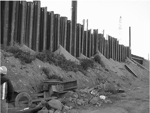
31 Soldier Pile and Lagging Walls Soldier Pile and Lagging Walls Soldier Pile and Lagging Soldier Pile and Lagging Walls This method of support involves the driving of steel H- piles or sections into the ground and placing lagging between the pile's flanges. Wood lagging is most common but steel or concrete lagging may also be used. If obstructions or rock is present, the piles are installed in pre-augered holes and can be concreted or backfilled with granular material to dredge line elevation. Cantilevered Soldier Pile and Lagging This type of wall is designed so that the passive resistance on the embedded portion of the pile, counteracts the active pressure acting on the cantilevered section of the wall. Cantilevered soldier pile walls are usually practical for excavations up to 20 feet in height. Anchored Soldier Pile and Lagging Same installation techniques as cantilevered soldier pile and lagging walls. Anchored soldier pile walls derive their support by two means: 1. Passive resistance in front of the embedded section of the piles. 2. Anchor forces near the top of the wall. Can be used to support walls up to 40 feet. Soldier Pile and Lagging- Advantages Can support higher excavations than driven sheeting When pre-augered holes are used, soldier pile walls can be installed in very compact soils, bouldery soils, and in rock Soldier Pile and Lagging- Disadvantages Much more expensive than sheeting Installation requires multiple steps (drilling, placing piles, concreting, placing lagging) Soldier pile walls are not impervious to water 25


32 20 th Statewide Conference On Local Bridges Training Session Anchored Wall Disadvantages Wider footprint than cantilevered walls because of wale/tieback assemby Tiebacks/wale assembly will need to be flipped for stage 2 excavation More ROW required for placement of anchors or deadman


33 Soldier Pile and Lagging Walls


34 20th Statewide Conference On Local Bridges Training Session


35 Soldier Pile and Lagging Walls


36 20 th Statewide Conference On Local Bridges Training Session


37 Soldier Pile and Lagging Walls
38 20 th Statewide Conference On Local Bridges Training Session Typical Soldier Pile Sections Driven vs. Preaugered Piles Boulders/Obstructions (shallow rock) Noise Vibration Control Alignment (permanent walls) Preaugered piles will require a little less embedment Preaugered piles are generally more expensive than driven piles Design Methods Cantilevered Soldier Pile Walls Simplified Method Anchored Soldier Pile Walls Free Earth Support Method Brom s Theory Failure was defined in two ways: the development of a plastic hinge in the pile; or for a short pile, an unlimited deflection. Pile head is assumed to be either fixed or free to rotate. Brom s assumed that the ultimate lateral resistance is equal to three times the Rankine passive pressure. Graphical Representation of the Passive Resistance Wedge Soldier Pile Wall Design Schematic S W W Forces x S Dredge Line Forces x 3W Forces x W Passive Side Active Side 32
 depth of embedment of the soldier pile 2) the minimum")
39 Soldier Pile and Lagging Walls Warning The pile flange width (W) or the diameter of the preaugered hole for the installation of the H-piles cannot be greater than one-third of the pile spacing (S) in the design calculations, i.e.: W S/3 Soldier Pile Wall Design The design of a soldier pile and lagging wall involves determination of: 1) depth of embedment of the soldier pile 2) the minimum required section modulus of the soldier piles 3) thickness of wooden lagging, section modulus of steel lagging or moment distribution for concrete lagging Soldier Pile Wall Design - Continued Timber Lagging Design For anchored walls, the following additional items need to be determined: 4) the wales 5) the deadman or earth and rock anchor 6) the location of the deadman with respect to the wall it supports Deadman Design A deadman may consist of soldier piles, large masses of concrete or a continuous sheet pile wall. Location Requirements for a Deadman Single Soil Layer A B C L W β α = 45 - ϕ/2 AB = L W tan α α β = 45 + ϕ/2 BC = L D tan β L W = Wall Length (in case of soldier pile walls, equal to exposed height H + 0.1H) L D = Deadman Length Minimum Distance Between = ABC = L W tan α + L D tan β L D Wall and Deadman = L W tan (45 - ϕ/2) + L D tan (45 + ϕ/2) 33
40 20 th Statewide Conference On Local Bridges Training Session Location Requirements for an Earth Anchor Single Soil Layer A B L W β 15 ft min. 5 ft α Free Length Bond Length α = tan (45 - ϕ/2) L W = 1.1 x H (exposed wall height) β = Anchor Inclination (typically 15 to 30 in soil) Rock Socketed Soldier Pile Wall Design Pressures and forces are determined as normal for the type of wall The design moment at the top of rock surface is determined from moment diagram, with the variability of rock surface being taken into account A geologist evaluates the rock cores and determines a socket depth based on rock quality, design moment, preauger hole diameter, and soldier pile spacing Rock Socket Design Example Item Numbers Item nn Holes in Earth for Soldier Pile and Lagging Wall Item nn Rock Sockets for Soldier Pile and Lagging Wall Item nn Soldier Piles for Soldier Pile and Lagging Wall Item nn Untreated Wood Lagging for Soldier Pile and Lagging Wall Item Grouted Tiebacks (Temporary) Item Grouted Tiebacks (Permanent) Item Steel Ties (Temporary) Item Steel Ties (Permanent) Wales and braces are typically paid for under the lagging item. 57 Detailing The following information should be shown on the contract plans: Plan location of the soldier pile wall placement Table showing: Pile station and offset (or coordinates) Top and toe soldier pile elevations Estimated pile length Depth of excavation Assumed rock elevation (if applicable) Minimum rock socket (if applicable) Minimum soldier pile section modulus Recommended soldier pile shape Minimum pre-auger hole diameter Detailing - Continued Typical section(s) showing: Payment lines Location of wales or bracing (if applicable) Location of tiebacks or deadman (if applicable) Minimum section modulus of wales and/or size of bracing (if applicable) Minimum section modulus of deadman (if applicable) Table showing the soil parameters used in the design 34


41 Soldier Pile and Lagging Walls BD-EE11E Example Example Questions 1. Predrilling for soldier piles may be necessary to: a. Reduce the likely hood of disturbance to adjacent utilities b. Remove obstructions which the pile could not be driven through c. Increase the passive soil resistance d. All of the above 2. The value of Brom s factor applied to the pile width is: a b. 1 c. 3 d Questions 3. Active earth force on sheeting is calculated per foot. Active force on a soldier pile wall above the dredge line is calculated per: a. Foot b. Pile width c. Pile width times Brom s factor d. Pile spacing 4. The pile flange width or diameter of the preauger hole cannot be greater than the following for design purposes: a. 1/10 th the pile spacing b. 1/3 rd the pile spacing c. The pile spacing d. Three times the pile spacing 35

42 20 th Statewide Conference On Local Bridges Training Session Braced Walls (35 minutes) Braced Walls Braced Walls A braced wall is a retaining structure (usually temporary in nature) which is used to support the sides of deep excavations. A wall with more than one anchor or strut level is considered a braced wall. Virtually any wall height can be supported with a braced wall as long as you have something to brace against. Braced Walls Continued Braced Walls- Advantages Can support virtually any height excavation Can be designed with little to no penetration below bottom of excavation Internal External Both walls are considered braced walls for design purposes. Braced Walls- Disadvantages Usually a more expensive option than cantilevered or anchored walls Internal struts can get in the way of construction equipment or the structure being constructed 6 36


43 Braced Walls


44 20th Statewide Conference On Local Bridges Training Session


45 Braced Walls


46 20th Statewide Conference On Local Bridges Training Session


.")

47 Braced Walls Braced Wall Design Trapezoidal earth pressure distribution is used. Results in less active force than traditional distributions (Rankine or Coulomb). Passive pressure forces are not used to support braced walls, braces take all loads
48 20 th Statewide Conference On Local Bridges Training Session Braced Wall Design The design of braced walls requires the determination of: a) The lateral pressures that act on the wall b) The maximum bending moment in the wall d) The section modulus required of the wall e) The strut loads f) The wale loads Steps 1 and 2 Step 1 - Determine the Soil Profile and Soil Parameters. Step 2 - Plot lateral earth pressures. Lateral Earth Pressures for Braced Walls a. Earth pressure distributions: Hydrostatic/Surcharge Pressures b. If groundwater is present, add its pressure to the trapezoidal soil pressure (see (b) below): c. If surcharge load is present, add the lateral component of the surcharge load to the soil pressure distribution (see (c) below): H H W γ W H W K A q (a) (b) (c) Structural Analysis Structural Analysis Continued The wall may be designed either as a continuous beam supported at the strut levels, or by assuming that pins exist at each strut, (except the top and bottom struts), thereby making each span statically determinate. Although it is slightly more conservative, in order to simplify the analysis, the following procedure assumes that the wall acts as a simply supported beam with pins at each strut. 42
49 Braced Walls Structural Analysis Continued Step 3 Step 3 Wall Design If the sheeting/piles are embedded at least 4 feet below the bottom of excavation, it is customary to assume a support at the bottom of the excavation. a. Determine the maximum bending moment and required embedment depth of the sheeting/piles for each stage of excavation using cantilevered and anchored analyses methods for Stage I and II and by braced wall design methods for Stage III to the final stage. Strut 1 Strut 2 Strut 3 4 ft min. Step 3 Continued b. Determine the maximum bending moment in sheeting/piles between wales for the final stage. The maximum bending moment per foot of width along the sheeting may be computed using: M MAX = 1/8 wl 2 (between struts) = ½ wl 1(2) 2 (about top and bottom strut) w = average lateral pressure on the wall over the longest span L = distance between wales L 1 = distance between top of excavation and first strut L 2 = distance between bottom strut and excavation line The vertical spacing between the struts may be reduced if the moments in the wall are too large. Step 3 Continued c. The minimum required section modulus of the sheeting/piles can then be determined using: M MAX σ ALL S MIN = M MAX /σ ALL = maximum moment calculated from either step 3(a) or 3(b) = allowable bending stress of sheeting material = 25 KSI for A328 Steel Sheet Piling = 30 KSI for Steel H-Pile (A50) = 1.2 KSI for Wood d. Select a sheeting/pile section with a section modulus equal to or greater than the section modulus calculated in Step 3(c). Step 3 Continued Figure 1 e. Check for bottom heave or piping conditions using Figures 1 and 2. If bottom heave or piping conditions exist, consideration should be given for alternative methods of excavations. Note that soldier piles will not affect piping conditions and should not be used if there is potential for piping. Stability Against Heave in Cohesive Soils (After NAVFAC DM-7, 1971) 43
 b.")
50 20 th Statewide Conference On Local Bridges Training Session Figure 2 Step 4 Calculate Strut Loads Step 4 a. Develop freebody diagrams from the soil pressure diagram and axial strut loads as shown below: Stability Against Piing in Non-cohesive Soils (After NAVFAC DM-7, 1971) b. Solve freebody diagrams for the axial strut load per lineal foot of wall (F A, F B, F C, F D ). Step 4 Continued c. Multiply the axial strut load per linear foot of wall by the horizontal strut spacing and a factor of safety of 1.5 to get the design strut loads. Step 5 Step 5 - Determine the maximum bending moment generated within the wale as follows: M MAX = 1/8 wl 2 d. If the axial loads per strut are not within acceptable limits, adjust the strut spacing and re-analyze the system. w = axial strut load per lin. ft. (from Step 4b) L = horizontal distance between struts Step 6 Step 6 Design the struts/anchors with conventional structural analyses methods. Since the strut loads were increased by a factor of 1.5 in Step 4, no further safety factors are required in the strut/anchor design. Item Numbers Item Temporary Sheeting Item Interim Sheeting Item nn Holes in Earth for Soldier Pile and Lagging Wall Item nn Rock Sockets for Soldier Pile and Lagging Wall Item nn Soldier Piles for Soldier Pile and Lagging Wall Item nn Untreated Wood Lagging for Soldier Pile and Lagging Wall Item Grouted Tiebacks (Temporary) Item Grouted Tiebacks (Permanent) Item Steel Ties (Temporary) Item Steel Ties (Permanent) Wales and braces are typically paid for under the lagging item. 44

 Example Example 58 Questions 1. A braced wall must always: a. Have one level of bracing/anchors b. Have 2 or more levels of bracing/anchors c. Have a minimum of 3 levels of bracing/anchors d.")
51 Braced Walls Detailing Show the appropriate information on the contract plans as described in the anchored sheeting/anchored soldier pile sections. BD-EE10E Refer to the following BD sheets: BD-EE10E Excavation and Embankment Braced Excavation Details BD-EE11E Excavation and Embankment Soldier Pile and Lagging Wall Sample Details BD-EE12E Excavation and Embankment Tieback Wall Details BD-EE15E Excavation and Embankment Sample Drawing of Stage Construction (1 of 2) BD-EE16E Excavation and Embankment Sample Drawing of Stage Construction (2 of 2) Example Example 58 Questions 1. A braced wall must always: a. Have one level of bracing/anchors b. Have 2 or more levels of bracing/anchors c. Have a minimum of 3 levels of bracing/anchors d. Be braced against a wall on the opposite side of the excavation 2. Braced walls may utilize: a. Steel struts b. Timber struts c. Grouted soil anchors d. All of the above Questions 3. Since braced sheeting walls have generally small embedments, additional design concerns are: a. Piping and heaving b. Bearing and rotating c. Sliding and eccentricity d. All of the above 4. In design of a braced wall, lateral active earth forces are calculated with: a. Triangular pressure distributions b. Circular pressure distributions c. Trapezoidal or rectangular pressure distributions d. None of the above 45
52


53 Geotechnical Design Proceedure for Flexible Wall Systems GEOTECHNICAL DESIGN PROCEDURE FOR FLEXIBLE WALL SYSTEMS Geotechnical Design Proceedure for Flexible Wall Systems GEOTECHNICAL DESIGN PROCEDURE GDP-11 Revision #3 GEOTECHNICAL ENGINEERING BUREAU APRIL 2007 NEW YORK STATE DEPARTMENT OF TRANSPORTATION 47
54 20 th Statewide Conference On Local Bridges Training Session GEOTECHNICAL DESIGN PROCEDURE: GEOTECHNICAL DESIGN PROCEDURE FOR FLEXIBLE WALL SYSTEMS GDP-11 Revision #3 STATE OF NEW YORK DEPARTMENT OF TRANSPORTATION GEOTECHNICAL ENGINEERING BUREAU APRIL 2007 EB Page 1 of 19 48
55 Geotechnical Design Proceedure for Flexible Wall Systems TABLE OF CONTENTS I. INTRODUCTION...4 A. Purpose...4 B. General Discussion...4 C. Soil Parameters...4 II. DESIGN PREMISE...5 A. Lateral Earth Pressures...5 B. Factor of Safety...8 III. FLEXIBLE CANTILEVERED WALLS...9 A. General...9 B. Analysis...9 C. Constructionability...10 IV. FLEXIBLE ANCHORED WALLS...11 A. General...11 B. Analysis Single Row of Anchors Multiple Rows of Anchors...12 C. Anchor Types...12 D. Constructability...13 V. REVIEW REQUIREMENTS...16 A. General...16 B. Flexible Cantilevered Walls...16 C. Flexible Anchored Walls...16 REFERENCES...18 APPENDICIES...19 A. Earth Pressures... A-1 Surcharge Loads... A-1 Hydrostatic Loads... A-1 Inclined Backfill... A-2 Inclined Foreslope... A-3 Railroad Embankment Zones and Excavation Limits... A-4 B. Recommended Thickness of Wood Lagging... B-1 C. Earth Pressures for Braced Excavation...C-1 Deadman Pressure Distribution & Location Requirements...C-2 EB Page 2 of 19 49
56 20 th Statewide Conference On Local Bridges Training Session D. Design Guidelines... D-1 For Use of the Soldier Pile and Lagging Wall Specifications... D-1 For Selecting a Soldier Pile Section for a Soldier Pile and Lagging Wall with Rock Sockets... D-5 For Use of the Sheeting and Excavation Protection System Specifications... D-11 For Use of the Grouted Tieback Specifications... D-11 For Use of the Steel Ties Specifications... D-12 E. Example Problems... E-1 Cantilevered Sheeting Wall (US Customary Units)... E-1 Anchored Sheeting Wall (US Customary Units)... E-3 F. Example Problems... F-1 Cantilevered Sheeting Wall (International System of Units)... F-1 Anchored Sheeting Wall (International System of Units)... F-3 EB Page 3 of 19 50
57 Geotechnical Design Proceedure for Flexible Wall Systems I. INTRODUCTION A. Purpose The purpose of this document is to provide an acceptable design method and theory for the geotechnical design of flexible cantilevered or anchored retaining walls to be constructed on New York State Department of Transportation projects. The following text provides a general discussion and design guidelines for these flexible wall systems. This document provides any designer with a framework for progressing a design and an understanding of the criteria which can be used during a geotechnical review. All structural aspects of these wall systems shall be performed in accordance with the Department s accepted procedures. B. General Discussion Flexible cantilevered or anchored retaining walls are defined in this document to include temporary or permanent flexible wall systems, or shoring systems, comprised of sheeting or soldier piles and lagging. An anchored system may include the aforementioned shoring systems supported by grouted tieback anchors, anchors to a deadman, rakers to a foundation block or braces or struts to an equivalent or existing wall system or structural element. Sheeting members of a shoring system are structural units which, when connected one to another, will form a continuous wall. The wall continuity is usually obtained by interlocking devices formed as part of the manufactured product. In New York State, the majority of the sheeting used is made of steel, with timber, vinyl, and concrete used less often. Soldier piles used as part of a shoring system are structural units, or members, which are spaced at set intervals. A lagging material is placed between the soldier piles to complete the shoring system. In New York State, the majority of the soldier piles used are made of steel, with concrete and timber used less often. The lagging material is usually dependent upon the design life of the wall. A temporary wall will usually incorporate timber lagging, with steel sheeting as lagging used less often. A permanent wall will usually incorporate concrete lagging with an architectural finish. C. Soil Parameters Soil parameters are the design assumptions which characterize the soil type. Typically, designs are progressed using effective stress parameters to account for long-term stability of the flexible wall system. For projects in design, the wall designer will be provided the soil parameters to use in the design of the flexible wall system. For projects in construction, the soil and loading parameters for the design of the detailed wall are as indicated in the contract plans. If a flexible wall system is proposed in an area which soil parameters are not listed, the Contractor shall contact the Engineer, who shall relay the request to the D.C.E.S. EB Page 4 of 19 51
58 20 th Statewide Conference On Local Bridges Training Session II. DESIGN PREMISE A. Lateral Earth Pressures A flexible wall system design is required to resist the anticipated lateral pressures without undergoing significant or excessive lateral deflections. The following list provides an acceptable geotechnical theory for the development of the lateral earth pressures and potential external loads and soil backfill configurations which must be accounted for in design: 1. Earth Pressure Theory: Use the Rankine Theory for the development of earth pressures on a flexible wall system. This theory assumes that wall friction (δ) equals zero. 2. Surcharge Loads: The term surcharge refers to an additional loading on the proposed wall system. This term usually refers to traffic loading that is in proximity to the wall system. Use the Spangler Method of analysis (area load of finite length) or Boussinesq Method of analysis to determine the lateral pressure caused by the surcharge loading. The uniform surcharge is usually given a value of 250 psf (12 kpa) or an equivalent height of fill. If the designer knows that heavier construction equipment will be in the vicinity of the wall, the surcharge loading shall be increased accordingly. A uniform surcharge of at least 250 psf (12 kpa) is always assumed at the top of a wall that has a level backfill. See Appendix Page A-1. For analysis of railroad loadings, refer to 6. Railroad Loading of this Section. 3. Hydrostatic Pressure: The identification of the existing groundwater table is necessary to design for sufficient support against all possible loadings. Since the locks of sheeting are more or less water tight when installed and become more watertight as soil is drawn in, water can be trapped behind the wall causing a head imbalance and greatly increasing the total load. Therefore, the elevation, or head difference, shall be accounted for in design of the wall system. The hydrostatic head is the difference between the groundwater elevation and the bottom of dewatered excavation. See Appendix Page A Inclined Backfill: An inclined backfill will induce an additional load on the wall. See Appendix Page A-2. This situation shall be analyzed by the following: EB Page 5 of 19 52
59 Geotechnical Design Proceedure for Flexible Wall Systems Infinite Slope If the backfill slope remains inclined beyond the limits of the active wedge, the backfill slope shall be assumed to extend infinitely away from the wall at an angle β. Using this condition, the Rankine earth pressure is a function of the angle β. To compute horizontal earth pressures, the resulting earth pressure must be adjusted by the backslope angle. Subsequent active earth forces are found using these adjusted earth pressures. Finite Slope If the backfill slope changes to horizontal within the limits of the active wedge of failure, the slope may be analyzed in two ways: A B The broken back slope design (A.R.E.A.) method may be used. This method is described in Section 5: Retaining Walls in the Standard Specifications for Highway Bridges, Adopted by the American Association of State Highway and Transportation Officials (A.A.S.H.T.O.), Seventeenth Edition. The sloping backfill may be assumed to be equivalent to a horizontal surcharge loading, located an offset of one-half the distance from the wall to the slope break. The surcharge loading shall be equivalent to the full height of the slope. 5. Inclined Foreslope: An inclined foreslope, or slope in front of the wall system, will reduce the amount of passive resistance available to resist loadings. See Appendix Page A-3. This situation shall be analyzed by the following: Infinite Slope If the foreslope extends beyond the passive wedge, the foreslope shall be assumed to extend infinitely away from the wall at an angle β. Using this condition, the Rankine earth pressure is a function of the angle β. To compute horizontal earth pressures, the resulting earth pressure must be adjusted by the foreslope angle. Subsequent passive earth forces are found using these adjusted earth pressures. Finite Slope If the foreslope changes to horizontal within the limits of the passive wedge of failure, the slope shall be assumed to be finite. In this case, the slope may be analyzed in two ways: EB Page 6 of 19 53
60 20 th Statewide Conference On Local Bridges Training Session A. Infinite slope as noted above. B. An excavation to the bottom of the slope. Engineering judgment shall then be applied when determining which solution to use. Note in both the infinite and finite slope cases, if the angle β is equal to or greater than the internal angle of friction of the soil, the excavation shall be assumed to extend down to the bottom of the slope. 6. Railroad Loading: When the proposed excavation requires the support of railroad loads, the designer shall follow all current applicable railroad requirements. Embankment Zones and Excavation Restrictions are described in Chapter 23 of the Highway Design Manual. See Appendix Page A-4. The system shall be designed to carry E-80 live load consisting of 80 kips axles spaced 5 ft. on centers (356 kn axles spaced 1.5 m on centers). A lower value load can be used if the railroad indicates, in writing, that the lower value is acceptable for the specific site. Use the Spangler Method of analysis (area load of infinite length) or the Boussinesq Method of analysis to determine the lateral pressure caused by the railroad loading. The load on the track shall be taken as a strip load with a width equal to the length of the ties (8 ft. 6 in.) (2.6 m). The vertical surcharge caused by each axle shall be equal to the axle weight divided by the tie length and the axle spacing. 7. Cohesive Soil: Due to the variability of the length of time a shoring system is in place, cohesive soils shall be modeled in the drained condition. These soils shall be modeled as cohesiveless soils using the drained internal angle of friction. Typically, drained internal angles of friction for New York State clays range from 22 to 26 (undrained shear strength=0). EB Page 7 of 19 54
61 Geotechnical Design Proceedure for Flexible Wall Systems B. Factor of Safety A factor of safety (F.S.) shall be applied to the coefficient of passive earth pressure (Kp). The value for the factor of safety is dependent on the design life of the wall (temporary or permanent). The passive pressure coefficients (Kp ) used in the design calculations shall be reduced as follows: 1. Temporary Retaining Wall: The factor of safety (F.S.) for a temporary wall is Kp = Kp / Permanent Retaining Wall: The factor of safety (F.S.) for a permanent wall is Kp = Kp / EB Page 8 of 19 55
62 20 th Statewide Conference On Local Bridges Training Session III. FLEXIBLE CANTILEVERED WALLS A. General Sheeting is driven to a depth sufficient for the passive pressure exerted on the embedded portion to resist the lateral active earth pressures acting on the cantilevered section. To achieve the required passive earth pressure resistance, embedment depths can often be quite high. Therefore, due to limitations on the availability of certain section modulus and its associated costs, cantilevered sheeting walls are usually practical to a maximum height of approximately 15 ft. (4.6 m). Soldier piles of a soldier pile and lagging wall system are vertical structural elements spaced at set intervals, typically 6 ft. to 10 ft. (1.8 m to 3.0 m). A soldier pile and lagging wall also derives its resistance from the embedded portion of the wall but, because of the higher available section modulus, greater excavation depths can be supported as compared to those supported by sheeting. Cantilevered soldier piles are usually practical for excavations up to approximately 20 ft. (6 m) in height. The minimum timber lagging thickness for a soldier pile and lagging wall should be determined from the table in Appendix B, taken from Lateral Support Systems and Underpinning, Vol. 1. Design and Construction, FHWA-RD-75128, April Additional design guidance for sheeting and soldier pile and lagging walls is provided and/or referenced in Appendix D. B. Analysis Use either the Simplified Method or the Conventional Method for the design of a cantilevered sheeting wall. To account for the differences between the two methods, the calculated depth of embedment, obtained using the Simplified Method, shall be increased by 20%. This increase is not a factor of safety. The factor of safety shall be applied to the passive pressure coefficient as stated in II. Design Premise: B. Factor of Safety. Use either the Simplified Method or the Conventional Method of analysis for the development of the lateral pressures on a soldier pile and lagging wall. However, as opposed to a sheeting wall which is analyzed per foot (meter) of wall, the calculations for the design of a soldier pile and lagging wall must account for the spacing of the individual soldier piles. To determine the active pressures above the dredgeline, include a factor equivalent to the spacing in the calculations. To determine the active pressures below the dredgeline, include a factor equivalent to the width of the soldier pile (for driven piles), or diameter of the hole (for piles installed in excavated holes) in the calculations. To determine the passive resistance of a soldier pile embedded in soil, assume that the net passive resistance is mobilized across a maximum of three times the soldier pile width (for driven piles), or three times the diameter of the hole (for piles installed in excavated holes). EB Page 9 of 19 56
63 Geotechnical Design Proceedure for Flexible Wall Systems Both the Simplified and Conventional Method of analyses are outlined in USS Steel Sheet Piling Manual. The Simplified Method is also described in Section 5: Retaining Walls in the Standard Specifications for Highway Bridges, Adopted by the American Association of State Highway and Transportation Officials (A.A.S.H.T.O.), Seventeenth Edition. The Conventional Method can also be found in such references as: Foundation Analysis and Design, Fourth Edition by Joseph E. Bowles and Foundations and Earth Structures by the Department of the Navy, Naval Facilities Engineering Command, Design Manual 7.2. C. Constructability Prior to the analysis, the designer shall evaluate the site conditions and subsurface profile to determine which type of flexible wall system is appropriate. Subsurface profiles which include cobbles, boulders and/or very compact material are sites where sheeting is not recommended and the designer should investigate alternate wall systems such as soldier piles and lagging. The designer should also focus on the type and size of equipment that will be needed to install the wall members. The designer should contemplate the limits of the wall with respect to the existing site conditions and include the design of any necessary connections. These considerations are valid for both cantilevered and anchored wall systems. EB Page 10 of 19 57
64 20 th Statewide Conference On Local Bridges Training Session IV. FLEXIBLE ANCHORED WALLS A. General When the height of excavation increases over 15 ft. (4.6 m), or if the embedment depth is limited (for example, the presence of boulders or bedrock), it becomes necessary to investigate the use of additional support for the wall system. An anchored wall derives its support by the passive pressure on the front of the embedded portion of the wall and the anchor tie rod near the top of the wall. Anchored walls are suitable for heights up to approximately 35 ft. (10.5 m). An additional factor of safety of 1.5 shall be applied to all anchor and brace loads. Each phase of construction of an anchored wall shall be analyzed. Each phase of construction affects the lateral earth pressures on the sheeting or soldier piles and therefore, the embedment and section modulus requirements. Ex.: Phase I: cantilever analysis (excavation to install first anchor), Phase II: anchored analysis (excavation below first anchor to install second anchor), Phase III: multiple anchor analysis (excavation below second anchor to install third anchor), etc...final Phase: multiple anchor analysis. Additional design guidance for grouted tiebacks and steel ties is provided and/or referenced in Appendix D. B. Analysis 1. Single Row of Anchors: Use the Free Earth Support Method for the design of an anchored sheeting or soldier pile and lagging wall. The Free Earth Support Method assumes the wall is rigid and may rotate at the anchor level. For the design of an anchored soldier pile and lagging wall system, the design must account for the spacing of the individual soldier piles as stated in III. Flexible Cantilevered Walls: B. Analysis. The designer shall analyze the effect of any additional vertical or horizontal loads imposed on the soldier piles or sheeting by the angle (orientation with respect to the wall) of the anchor. The embedment of sheeting or H-piles (or other sections used as soldier piles) below the bottom of the excavation should be checked to ensure that it is sufficient to support the weight of the wall and the vertical component of the tieback force. The factor of safety should be at least 1.5 based on the design load, assuming resistance to the vertical load below the bottom of excavation only. Pile and sheeting bearing capacity should be calculated as shown in the manual on Design and Construction of Driven Pile Foundations, FHWA-HI , Rev. November 1998 with P d and P D equal to the values on the excavation side of the wall. EB Page 11 of 19 58
65 Geotechnical Design Proceedure for Flexible Wall Systems 2. Multiple Row of Anchors: Use the method of analysis for a braced excavation, based on a rectangular (Terzaghi & Peck, 1967) or trapezoidal (Terzaghi & Peck, 1948) pressure distribution. The rectangular pressure distribution is outlined in such references as: Foundation Analysis and Design, Fourth Edition by Joseph E. Bowles, Principles of Foundation Engineering, Second Edition by Braja M. Das and in Section 5: Retaining Walls in the Standard Specifications for Highway Bridges, Adopted by the American Association of State Highway and Transportation Officials (A.A.S.H.T.O.), Seventeenth Edition. See Appendix Page C-1. When a rectangular or trapezoidal pressure distribution is used, all of this pressure has to be resisted by the anchors and by the bending resistance of the sheeting or H-piles. Do not consider active or passive earth pressure below the bottom of the excavation when calculating the required anchor loads, unless groundwater level is above the bottom of excavation. In that case, passive pressure may be used to help resist active earth pressure and excess hydrostatic pressure. Due consideration should be given to the effect of uplift on the passive pressure and to the amount of movement required to mobilize full passive pressure. For the design of an anchored soldier pile and lagging wall system, the calculations shall account for the spacing of the individual soldier piles as stated in III. Flexible Cantilevered Walls: B. Analysis. The designer shall analyze the effect of any additional vertical or horizontal loads imposed on the soldier piles or sheeting by the angle (orientation with respect to the wall) of the anchor. The embedment of sheeting or H-piles (or other sections used as soldier piles) below the bottom of the excavation should be checked to ensure that it is sufficient to support the weight of the wall and the vertical component of the tieback force. The factor of safety should be at least 1.5 based on the design load, assuming resistance to the vertical load below the bottom of excavation only. Pile and sheeting bearing capacity should be calculated as shown in the manual on Design and Construction of Driven Pile Foundations, FHWA-HI , Rev. November 1998 with P d and P D equal to the values on the excavation side of the wall. C. Anchor Types The following are possible types of anchor support systems: 1. Grouted Tiebacks: A grouted tieback is a system used to transfer tensile loads from the flexible wall to soil or rock. It consists of all prestressing steel, or tendons, the anchorage, grout, coatings, sheathings, couplers and encapsulation (if applicable). EB Page 12 of 19 59
66 20 th Statewide Conference On Local Bridges Training Session 2. Deadman: A deadman may consist of large masses of precast or cast-in-place concrete, driven soldier piles or a continuous sheeting wall. The required depth of the deadman shall be analyzed based on the active and passive earth pressures exerted on the deadman. See Appendix Page C-2. Deadman anchors must be located a distance from the anchored wall such that they can fully mobilize their passive pressure resistance outside of the anchored wall s active zone. This is described in such references as: USS Steel Sheet Piling Manual and Foundation Analysis and Design, Fourth Edition by Joseph E. Bowles. See Appendix Page C Struts or Braces / Rakers: Struts or braces are structural members designed to resist pressure in the direction of their length. Struts are usually installed to extend from the flexible wall to an adjacent parallel structure. Rakers are struts that are positioned at an angle extending from the flexible wall to a foundation block or supporting substructure. D. Constructability Constructability concerns are outlined in III. Flexible Cantilevered Walls: C. Constructability. The following are additional considerations which must be addressed: 1. General: The mass stability of the earth-tieback-wall system will be checked by the Geotechnical Engineering Bureau unless the consultant agreement states that the consultant will do all the geotechnical design work for the project. The designer will be notified of any special requirements that have to be included in the contract to ensure mass stability. Sheeting Walls: In the case of permanent anchored sheeting walls (not H-pile and lagging walls with drainage zones) without special features that would permit water to drain from behind the wall (weep holes alone are ineffective), the effects of an unanticipated rise in groundwater level during periods of heavy precipitation should be considered. Unless detailed groundwater level analyses indicate otherwise, the final anchor design should be based on a 10 ft. (3 m) rise in the groundwater level compared to the highest groundwater level determined from subsurface explorations. To account for possible perched water conditions, multiply by 1.25 the calculated anchor loads above the groundwater level (after adding the 10 ft. (3 m) rise). EB Page 13 of 19 60
67 Geotechnical Design Proceedure for Flexible Wall Systems Soldier Pile and Lagging Walls: H-pile (or other type of solider pile) and lagging walls should not be used in excavations below groundwater level unless the design includes appropriate positive methods to control seepage. 2. Grouted Tiebacks: The presence of existing structures and utilities should be taken into account when deciding upon the location and inclination of anchors. The installation of the grouted tieback, location and inclination, should be surveyed against these existing site constraints. The design shall meet the requirements for minimum ground cover for the grouted tieback (Recommendations for Prestressed Rock and Soil Anchors, Post- Tensioning Institute, Fourth Edition: 2004). The minimum anchor free length is: a. 15 ft. (4.6 m) or b. the length of the tieback from the face of the wall to the theoretical failure plane plus H/5, whichever is greater. The theoretical failure plane is inclined at an angle of 45 - φ/2 with the vertical, where φ is the friction angle of the soil, if the backslope is horizontal. For cases where the backslope is not horizontal, the inclination of the failure plane should be determined from Foundations and Earth Structures, Design Manual 7-2, NAVFAC DM-7.2, May 1982, p , or by means of a trial wedge analysis. The point of intersection of the theoretical failure plane with the face of the wall for walls in non-plastic soils can be determined as follows: a. H-pile and lagging wall with single level of anchors: H/10 below the bottom of the excavation, Fig. 1(a). b. Sheeting wall with single level of anchors: Level below bottom of excavation where moment in sheet pile is zero. Fig. 1(a). c. H-pile and lagging wall with more than one level of anchors: Bottom of excavation, Fig. 1(b). d. Sheeting wall with more than one level of anchors and groundwater level below bottom of excavation: Bottom of excavation, Fig. 1(b). e. Sheeting wall with more than one level of anchors and groundwater level above bottom of excavation: Level below bottom of excavation where moment in sheeting is zero. EB Page 14 of 19 61
68 20 th Statewide Conference On Local Bridges Training Session Theoretical failure plane for H-piles and lagging H 0.1 H Point of zero moment (a) Theoretical failure plane for sheeting / /2 (b) Figure 1 - Location of Theoretical Failure Plane Theoretical failure plane 3. Deadman: Both the proposed maintenance and protection of traffic scheme and the construction sequencing should be evaluated to ensure that there is no interference with the method and sequence of tie rod installation and its subsequent functioning. 4. Struts or Braces / Rakers: The location and spacing of struts or rakers should be critiqued with respect to the allotted working space and proposed construction. Consideration should be given to access by workers, supplies and equipment. The installation of the raker block should be evaluated with respect to the support of the wall system. The wall should be analyzed for any additional excavation or other construction impacts necessary to install the raker block. EB Page 15 of 19 62
69 Geotechnical Design Proceedure for Flexible Wall Systems V. REVIEW REQUIREMENTS A. General All designs will be reviewed using the analyses and theories stated in this document. All designs that are part of a construction submittal shall be stamped by a currently registered New York State Professional Engineer and shall follow the methods described or yield comparable results. All designs shall be detailed in accordance with the current Departmental guidelines for the applicable item(s). Copies of these guidelines are available from the Geotechnical Engineering Bureau. B. Flexible Cantilevered Walls For review of the design of a flexible cantilevered wall, the following information is required: 1. All design assumptions. 2. Cite all reference material. Provide copies of relevant pages of any reference material that is used in the design and that is not included in the reference list on page Design elevations, including top and toe of sheeting or soldier pile, bottom of excavation, site specific soil layering and parameters. Cross sections are preferred. 4. Calculations or a computer design for the sheeting or soldier pile and lagging wall design. If a computer program is used, provide documentation of the assumptions used in writing the program. 5. Summary of constructability aspects of the proposed design as described in III. Flexible Cantilevered Walls: C: Constructability. An example design calculation is shown on Appendix Pages E-1 & 2 (US Customary Units) or Pages F-1 & 2 (International System of Units). C. Flexible Anchored Walls For review of the design of a flexible anchored wall, the following information is required: 1. All design assumptions. 2. Cite all reference material. Provide copies of relevant pages of any reference material that is used in the design and that is not included in the reference list on page Design elevations, including top and toe of sheeting or soldier pile, bottom of excavation, location of wales or bracing, deadman/raker block location(s), site specific soil layering and parameters. Cross sections are preferred. EB Page 16 of 19 63
70 20 th Statewide Conference On Local Bridges Training Session 4. Calculations or a computer design for the anchored sheeting or soldier pile and lagging wall design. These calculations shall include each phase of construction. If a computer program is used, provide documentation of the assumptions used in writing the program. The design loads for the anchors/braces shall account for the proposed inclination (if applicable). 5. Calculations for the deadman or raker block design (if applicable). 6. Calculations for the waler design(s) showing connections. 7. For grouted tiebacks, specify proposed free length, inclination and corrosion protection (if applicable). 8. Summary of constructability aspects of the proposed design as described in IV. Flexible Anchored Walls: D. Constructability. An example design calculation is shown on Appendix Pages E-3, 4 & 5 (US Customary Units) or Pages F-3, 4, & 5 (International System of Units). EB Page 17 of 19 64
71 Geotechnical Design Proceedure for Flexible Wall Systems REFERENCES 1. USS Steel Sheet Piling Design Manual, Updated and reprinted by US Department of Transportation / FHWA with permission: July, Foundations and Earth Structures by the Department of the Navy, Naval Facilities Engineering Command, Design Manual 7.2: May, Foundation Analysis and Design, Fourth Edition by Joseph E. Bowles. 4. Principles of Foundation Engineering, Second Edition by Braja M. Das. 5. Section 5: Retaining Walls in the Standard Specifications for Highway Bridges, Adopted by the American Association of State Highway and Transportation Officials (A.A.S.H.T.O.), Seventeenth Edition, Permanent Ground Anchors, FHWA-DP , Demonstration Projects Division: April, Recommendations for Prestressed Rock and Soil Anchors, Post-Tensioning Institute, Fourth Edition: FHWA Report No. FHWA-RD Lateral Support Systems and Underpinning, Vol. I, Final Report April, Soil Mechanics in Engineering Practice, 2 nd ed., K. Terzaghi and R. B. Peck, 1967, John Wiley and Sons, New York. The first edition was published in Design and Construction of Driven Pile Foundations, FHWA-HI Revised November, APPENDICIES EB Page 18 of 19 65
72 20 th Statewide Conference On Local Bridges Training Session Earth Pressures Backslope Foreslope Soil:, Where: K A = 1 - sin 1 + sin D Passive Earth Pressure Distribution Active Earth Pressure Distribution H K P = 1 + sin 1 - sin K P = K P /F.S. K P D K A H Surcharge Loads q Surcharge Pressure Distribution Hydrostatic Loads K A q Hydrostatic Pressure Distribution H W W H W EB A-1 66
73 Geotechnical Design Proceedure for Flexible Wall Systems Inclined Backfill Plot the anticipated active failure wedge line against the slope line. If the slope line intersec the active failure wedge line, the slope can be considered infinite (Case 1), otherwise the slo be modeled by using an equivalent surcharge (Case 2). Active Failure Wedge Case 1 Case /2 Active Failure Wedge Case 1 - Infinite Slope Analysis Active Earth Pressure Distribution H K AR H(cos ) Where : K AR = (cos ) [cos - (cos 2 - cos 2 ) 0.5 ] [cos + (cos 2 - cos 2 ) 0.5 ] Case 2 - Equivalent Surcharge Method X X/2 Y Y X/2 q = Y Surcharge Pressure Distribution K A q = K A Y EB A-2 67
74 20 th Statewide Conference On Local Bridges Training Session Inclined Foreslope Plot the anticipated passive failure wedge line against the slope line. If the slope line interse with the passive failure wedge line, the slope can be considered infinite (Case 1), otherwise t slope can be accounted for by increasing the depth of excavation (Case 2). In the latter case, methods should be analyzed and engineering judgement used to determine the solution. Passive Failure Wedge Case 2 Case 1 Passive Failure Wedge 45 + /2 Case 1 - Infinite Slope Analysis D Passive Pressure Distribution K PR D(cos ) Where : K PR = (cos ) [cos + (cos 2 - cos 2 ) 0.5 ] [cos - (cos 2 - cos 2 ) 0.5 ] K PR = K PR /F.S. Case 2 - Increase Excavation Depth to Compensate for Slope H 1 H 2 = H 1 + X X Passive Pressure Distribution K P D D EB A-3 68
 Revision No.")
75 Geotechnical Design Proceedure for Flexible Wall Systems Chapter 23: Railroads HIGHWAY DESIGN MANUAL (HDM) Revision No. 39 EB A-4 69