Rt. 15/29 (SBL) Bridge Superstructure Replacement and Roadway Widening
|
|
|
- Elisabeth Baker
- 5 years ago
- Views:
Transcription
1 Rt. 15/29 (SBL) Bridge Superstructure Replacement and Roadway Widening March 5, 2009 Nicholas J. Roper NOVA District Bridge Engineer Robert F. Price Resident Administrator of Loudoun/ Prince William Construction


2 Prior to Construction West side view of SBL bridge prior to construction East side view of SBL bridge prior to construction 2
3 Project Information Location: The Route 15/29 (SBL) Bridge Superstructure Replacement and Roadway Widening Project over Broad Run is located in Prince William County, 0.55 Mile North of Route 215. Scope: Work includes replace and widen existing bridge superstructures with offsite-fabricated superstructure segments, substructure concrete widening and repairs, re-alignment and approach work. Superstructure: 3-Span, Concrete T beam, Simply Supported Substructure: Wall type piers and abutments Year Built: 1952 ADT: 25,000 Condition: Structurally deficient and functionally obsolete. 3

4 Project Limits 4 Project limits within the Buckland Historical District and the Mosby Heritage Area
5 Construction Concept
6 Typical Sections 2-6 ½ ½ [Median] Widen 5-4 [Exterior Edge] 3-2 ½ Existing Bridge 3-2 ½ Roadway Lane 12 Lane 8-0 Shoulder 4-0 Shoulder Proposed Modular Bridge
7 Proposed Modular Structure Module Configuration: Each Module Consists of a Prefabricated Conc. Deck on Two Steel Beams Module Width Arrangement in Transverse Section: (7-10 ) (8-9 ) (9-0 )(12-11 ) Module Length = Span Length (~ 44 ) Max. Module Weight = ~35 tons (~30 tons w/ Lightweight Concrete) Longitudinal Joints between Modules: Grouted/Waterproofed Keyways Diaphragms between Modules: Module Width Field Installed Steel Diaphragms Deck Parapets: Plant Cast Concrete Asphalt Overlay: 3 Thick with Waterproof Membrane 7
8 Proposed Sequence of Construction Span A Span B Span C Stage IV Stage III Stage II Stage I [Median] 8
9 Extending Pier with External PT ~ 6 ~36 [Median] Cap External Post- Tensioning ~ 11 Corbel (Cast-in-Place, or Prefabricated, Match Cast) Pier Legend: Existing Structure Proposed Structure Grouted Dowel Typ. Footing 9
10 Extending Abutment A (Typical) PLAN Footing Backwall Seat Seat Backwall Footing Concrete Removal Legend: Existing Structure Proposed Structure Backwall Seat Grouted Dowel, Typ. 10 ELEVATION Footing
11 Proposed Construction Stage I at Night: 9 p.m. to 5 a.m. ~ Lane 2-6 ½ Transport Lane [Median] [Exterior Edge] Temp. Plate Over Gap, or Fill in with Asphalt 11

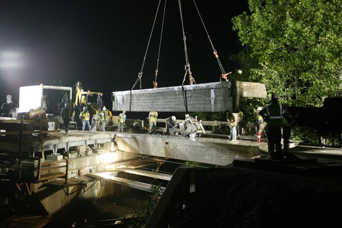
12 James River Bridge Transport lane to haul away existing segment and install new module Truck Parked on Transport Lane 12 Two cranes lift a pre-constructed unit into place on the James River Bridge in Richmond, VA. (Photo: URS Corporation)
13 Proposed Construction Stage I Night Span A Span B Span C Traffic Barrier Traffic Lane Transport Lane Remove/Replace Superstructure Remove/Replace Superstructure Remove/Replace Superstructure Stage I Construction 13 NOTE: Stages III and IV similar
14 Existing Median Crossover 400 South of Bridge Broad Run Existing Median Crossover 300 North of Bridge N Road Closed SB 15/29 Bridge Under Construction Median Road Closed Legend: Rte 15/29 SB Traffic Rte 15/29 NB Traffic Stage II MOT for Nighttime Construction 1. Close the SB bridge to traffic from 9 p.m. to 5 a.m. 2. Route the SB traffic on NB via the crossover 300 north of the bridge. 3. Route the SB traffic back on SB via the crossover 400 south of the bridge 4. Maintain both lanes of traffic on SB bridge from 5 a.m. to 9 p.m. 14
15 Proposed Construction Stage II at Night: 9 p.m. to 5 a.m. ~ ½ 8-9 Transport Lane 19-3 ½ 2-6 ½ [Median] [Exterior Edge] 15 Final Joint Configuration
16 Proposed Construction Stage II at Night Span A Span B Span C Transport Lane Stage II Construction Stage I Construction Remove/Replace Superstructure Remove/Replace Superstructure Remove/Replace Superstructure 16
17 Completed Structure Span A Span B Span C Railing Railing [Median] Roadway Lane 12 Lane 8-0 Shoulder 4-0 Shoulder
18 Construction Phase
19 Existing Bridge Elevation 44-2 Span A 42-6 Span B 44-2 Span C 19


20 Initial Construction Abutment B East side Pier 1, Pier 2 Under bridge view of Abutment B 20
21 Conflicts with Beams Existing beam seat conditions justified the weekend closure to enable total replacement. 2-6 ½ ½ Overlapping Beams [Median] Widen 5-4 Actual width of existing beam > than as-build plans 3-2 ½ Existing Bridge 3-2 ½ [Exterior Edge] 21


22 Beam Seat Construction Issues In conflict with existing beams 22

 in May")
23 High Water Before and after photos of high water after heavy rains (10 ) in May

24 High Water 24 Damages caused by heavy rain after installation of cofferdam (port-a-dam)

25 Cofferdams 25 Installation of an additional Cofferdam at Pier 1 needed as a result of high water to complete formwork and concrete pour

26 Initial Progress Abutment A 26 East side Abutment A, Pier 1 and Pier 2

27 Environmental Demolition Shield Installation of demolition shield 27

28 Weight Limitations Hand Rails Removed 28 Removal of existing handrails to reduce weight during the removal of segments

29 Steel Beams Galvanization and Shipping 29 Steel beams after galvanizing and shipment to Coastal Precast Systems, Inc.

30 Coastal Prefabricating Modular Deck Units 30

31 Revised Construction Sequence Revised MOT Plan for Weekend Closures 31
32 Revised Construction of Span A Span A Span B Span C Detour SB Traffic During Weekend Remove/Replace Superstructure [Median] 32
33 Revised Construction of Span B Span A Span B Span C Detour SB Traffic During Weekend Remove/Replace Superstructure [Median] 33
34 Revised Construction of Span C Span A Span B Span C Detour SB Traffic During Weekend [Median] Remove/Replace Superstructure 34
35 Completed Structure Span A Span B Span C Railing Railing [Median] Roadway Lane 12 Lane 8-0 Shoulder 4-0 Shoulder
36 Lessons Learned Conflicts With Beams Encourage full detailed survey/as-built investigation during Preliminary Engineering Phase. Design should use maximum tolerances to allow for field adjustments. Designers need to insure all specified materials are readily available (standard typical beam sizes). Existing Bridge Wider Existing Beam Widths Overlapping Beams [Median] Actual width of existing beam > than as-build plans [Exterior Edge] New Bridge 8-0 Shoulder Shoulder 36
 Crane")

37 Lessons Learned (Continued) Crane Issues Larger crane required Limited work area 37


38 38

39 Placing Asphalt at the Abutment and Sealing Deck Joints 39

40 Completed Structure with Asphalt Overlay 40