SIMULATED OFFICE PROJECT 2008 TECHNICAL REPORT
|
|
|
- Buddy Gordon
- 5 years ago
- Views:
Transcription
1 SIMULATED OFFICE PROJECT 2008 TECHNICAL REPORT NEW FACILITY FOR ADULT BASIC EDUCATION AND VOCATIONAL TRAINING By Leigh Hartl Student Number: A Report Submitted in Partial Fulfilment of the Requirements for the Degree of Master of Architecture M.Arch The School of Architecture, Planning and Housing Faculty of Humanities, Development and Social Sciences University of KwaZulu-Natal Durban, South Africa January, 2009
2

3 ii TECHNICAL REPORT Technical Report
4 iii ACKNOWLEDGEMENTS ACKNOWLEDGEMENTS I would like to thank the following for their assistance in compiling this research document: Carl for your technical assistance, advice and support Everyone at MWP for your help and encouragement Note: All figures and photographs are by the author, except where otherwise acknowledged.
5 iv TABLE OF CONTENTS TABLE OF CONTENTS Number Page i. Acknowledgements...iii. ii. Table of Contents... iv. CHAPTER 1: INTRODUCTION...1 CHAPTER 2: STRUCTURAL RESOLUTION Introduction Foundations Surface Bed Columns, Slabs and Beams Walls Roof Conclusion... 4 CHAPTER 3: FIRE REPORT Introduction Fire Fighting equipment and Escape Routes Conclusion...5 CHAPTER 4: MECHANICAL RESOLUTION Introduction HVAC Conclusion...6 CHAPTER 5: SERVICES Introduction Drainage Stormwater Disposal Water Supply Lifts Electrical Conclusion...8 CHAPTER 6: CONCLUSION...9 CHAPTER 7: APPENDIX I WORKING DRAWINGS...10
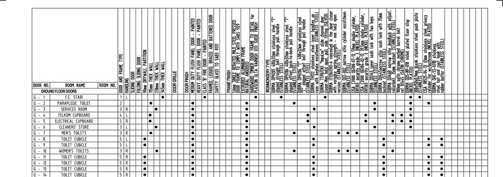
6 1 CHAPTER 1: INTRODUCTION 1 INTRODUCTION Outlined in this report are the various aspects required to technically document the proposed Centre for Adult Basic Education and Vocational Training for construction, during stage four of the standard services for which the architect is responsible. For the purposes of this technical report a portion of the proposed centre was considered, and sample working drawings have been prepared for this portion of the building. The purpose of this report is to illustrate the architect s role as a principal agent of the client in liaising with the various professional consultants. This report is to be read in conjunction with the working drawings attached as Appendix I.
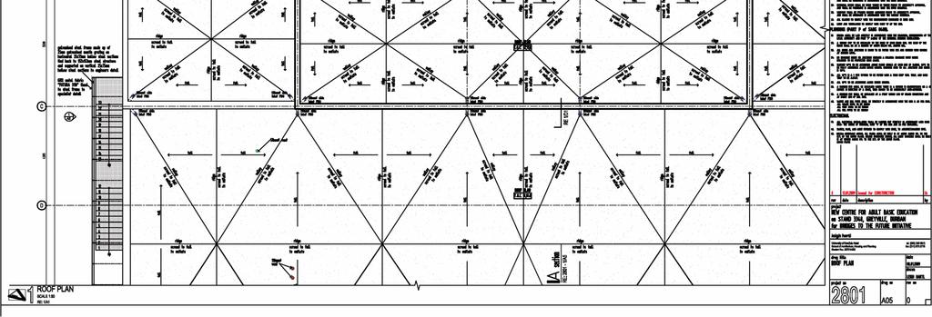
7 2 CHAPTER 2: STRUCTURAL RESOLUTION 2 STRUCTURAL RESOLUTION 2.1 Introduction The structural system of the building has been designed in order to allow for the long spans required to accommodate flexible utilisation of space and to provide the most appropriate spaces for the specific functions contained therein. Based on the working drawings produced by the architect, or preferably through a process of consultation and collaboration, a structural engineer will need to prepare a full set of structural design drawings, including designs for foundations, walls, columns, beams, slabs and roofs. The purpose of these drawing would be to clarify and specify overall sizes and materials and structural systems to be used in the proposed building. NOTE: All concrete and steel work (foundations, surface beds, slabs, beams, columns and roofs), while illustrated and dimensioned in the working drawings, will require the input of a structural engineer in order to finalise all dimensions, spans depths according to accommodation types and specific loads as determined by the engineer. 2.2 Foundations (To Comply with Part H of SABS 0400) A Geo-technical engineer would need to be employed in order to conduct a survey of the soil conditions of the site. Based on the recommendations arising from this investigation, the structural engineer will be instructed as to the type of foundations which will be appropriate for this particular site. In this case the site is located near the CBD of Durban, in the Warwick Junction Precinct, which has an extremely high water level. It is therefore anticipated that a combination of pile and strip foundation will be used. 2.3 Surface Beds (To Comply with Part J of SABS 0400) Surface beds are to be 150mm reinforced concrete as per the structural engineer s design and specification. The surface bed for the covered walkway is to be 100mm reinforced concrete as per the structural engineer s design and specification. Surface beds are to have saw cuts at maximum 450mm centres, and saw cuts, v-joints in screed and tiling joints are to coincide in order to minimise cracking brought about by settlement. Surface beds are to be on USB green underlay on well compacted fill to the engineer s details and specifications.
8 3 CHAPTER 2: STRUCTURAL RESOLUTION 2.4 Columns, Slabs and Beams (To Comply with Part B of SABS 0400) Columns which fall within walls are to 230x460mm reinforced concrete columns with 150mmØ PVC rainwater downpipes cast into the columns where indicated on plan, as per the engineer s details and specifications. Where illustrated within the learning resources centre, central aisle columns are to be 500mmØ reinforced concrete on ground floor, and 300mmØ on first and second floors (Re: 1/A02, 1/A03 & 1/A04). Generally slabs are to be 170mm thick reinforced concrete slabs with 25mm saw cut expansion joints at maximum 4500mm centres. Slabs to the book stack areas of the learning resources centre are to be 350mm reinforced concrete coffer slabs. Saw cuts, v-joints in screed and tiling joints are to coincide in order to minimise cracking brought about by settlement. Beam depths vary depending on the location and application, and most beams have a thickness of 230mm reinforced concrete, except where otherwise illustrated. 2.5 Walls (To Comply with Part K of SABS 0400) Walls are either 230mm brick walls or 345mm cavity walls. 230mm clay brickwork double skin walls are either for plaster and paint finish, or facebrick as illustrated on elevations. 345mm cavity walls are to be clay stock for plaster and paint finish with walls ties every four vertical course, spaced at approximately 1m 2. Internal walls are generally 115mm clay stock brick single skin walls for plaster and paint finish. 2.6 Roof (To Comply with Part L of SABS 0400) The building consists of two types of roofing systems, namely CHROMADEK profiled roof sheeting on steel girder trusses, and flat concrete slabs. In the sample portion of the building taken for the purposes of illustration for this project, roofs are predominantly flat slabs, except where illustrated at the covered walkways. Generally roof slabs are 170mm deep reinforced concrete slabs as per the engineer s detail and specification. Over the auditorium where the span is greater than the general roof slabs, the slab is 255mm reinforced concrete slab.
9 4 CHAPTER 2: STRUCTURAL RESOLUTION Roof slabs are to be insulated against solar heat gain with a 40mm thick ISOFOAM 'ISOBOARD' extruded polystyrene insulation board on a minimum 30mm cement screed blinding. Flat roofs are to be waterproofed with DERBIGUM or a similar approved product, to be painted silver, to be lain on a minimum 30mm cement screed to falls to outlets. 2.7 Conclusion The overall structural system of the proposed facility is a concrete grid system consisting of columns, beams and slabs with brick and glass infill panels. Coffer slabs have been used where necessary in order to cope with the increased loads typical of libraries. The use of a concrete structural grid allows for large spans to accommodate flexible internal design of spaces and allows for large openings which allow the advantages of natural lighting to be incorporated into the scheme.
10 5 CHAPTER 3: FIRE REPORT 3. FIRE REPORT 3.1. Introduction This chapter deals with the steps which are necessary to make a building compliant with the fire safety regulations in terms of Part T of the South African National Building Regulations (SABS 0400). In order to determine the requirements of compliance with the safety regulations the building is classified as follows: A3: Place of Instruction (SABS 0400; Table 1; p. 34). C2: Library (SABS 0400; Table 1; p. 34) Fire Fighting Equipment and Escape Routes (To Comply with Part T of SABS 0400) The requirements stipulated in Part T of the SABS 0400 which have been accommodated and illustrated in the illustrated portion of the proposed building are: One fire extinguisher per 200m 2. Fire extinguisher to be 9kg portable dry chemical type. One fire hose reel shall be provided per 500m 2 to accommodate 30m hose lengths. One fire hydrant per 1000m 2. Fire detection and smoke alarms to be installed throughout the building. An approved sprinkler system shall be installed. Operable windows at roof level to permit smoke ventilation. Not less than 2 escape routes are to be provided with the distance of travel not exceeding 45m. Exit doors shall open in the direction of travel along the escape route. The width of the escape route shall not be less than 1100mm. Water reticulation to fire fighting equipment shall be provided. Emergency routes shall be clearly marked and signposted to indicate the direction to be travelled in the case of an emergency Conclusion Further consultation with a specialised fire engineer or fire officer would ensure that the building is compliant with the fire safety regulations as laid out in the SABS 0400.
11 6 CHAPTER 4: MECHANICAL RESOLUTION 4. MECHANICAL RESOLUTION 4.1. Introduction The mechanical resolution of this building focuses mainly on the air conditioning system. This system is to be housed in the ceiling void and to be reached from the origin on ground floor below the raked floor of the auditorium, via the services room and vertical ducts HVAC (To Comply with Part TT43 of SABS 0400) Appropriate size and type of HVAC system is to be determined by the mechanical engineer. Space has been allocated to accommodate the mechanical ventilation system, but the specific design of the system is to be done by the mechanical engineer and is to be coordinated by the architect. Air conditioning is to comply with Part TT43 of SABS Conclusion Consultation with a mechanical engineer will serve to define the specifics of the HVAC system as well as to improve the efficiency of the system. The possibility of the installation of passive heating and cooling system will be based on the advice given by the mechanical engineer.
12 7 CHAPTER 5: SERVICES 5. SERVICES 5.1. Introduction Outlined in this chapter are the various services which are required in the building. The design of these systems and installations will be in consultation and coordination with the electrical, mechanical and civil engineers Drainage (To Comply with Part P of SABS 0400) The building will have a standard drainage system linking to the municipal sewer line. Sanitary fixtures are to be supplied based on the population of the building calculated as per Table 2 of Part A and Table 6 of Part P of the SABS All soil pipes, waste pipes, rodding eyes, inspection eyes and gullies are to comply with Part P of the SABS Stormwater Disposal (To Comply with Part R of SABS 0400) Gutters, valley gutters and downpipes are to comply with Part R of the SABS Access points to stormwater drains shall not be further apart than 40m Water Supply The mechanical engineer will be called upon to specify the implementation and installation of the water supply system as required. All piping shall be PVC and shall be sized according to the engineer s specifications Lifts (To Comply with Part SS3 & TT45-TT48 of SABS 0400) The appropriate lift is to be specified by the mechanical engineer, and the lift shaft and pit are to be designed by the structural engineer to fit within the allocated space Electrical (To Comply with Part OO6 of SABS 0400) All electrical cabling and conduits are to be specified and designed by the electrical engineer. All work is to comply with: SABS 0142 in terms of the code of practice for the wiring of the building. SABS 0114 in terms of the code for interior artificial lighting. Provision must be made to accommodate telephones, computer, internet and LAN cabling.
13 8 CHAPTER 5: SERVICES 5.7. Conclusion Further consultation with l engineers will be required in order to be able to produce layout drawings which will then be coordinated with the architect s working drawings.
14 9 CHAPTER 6: CONCLUSION 6. CONCLUSION This report briefly covers the major technical aspects of a building which need to be resolved for the purposes of construction. It also illustrates the roles played by some of the many professional consultants in the construction process. The most important aspect illustrated is that the architect, in the role of principal agent, has the responsibility if coordinating the information from all the consultants on the professional team in order to ensure that there are no clashes of services.


15 10 CHAPTER 7: APPENDIX I PRESENTATION DRAWINGS 7 Appendix I Working Drawings 10

16


17
18


19


20


21

22

23


24


25


26
27

28


29

30

31
32
33
34
35


36

37
38
39
40
41
42
43
44
45

46
47
48
49
50