|
|
|
- Mary Chase
- 5 years ago
- Views:
Transcription


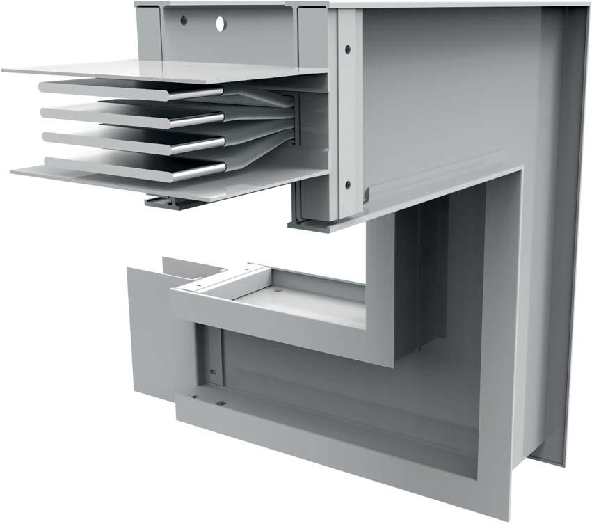
1 Power Xpert XP2 Aluminium
2 Eaton Power Xpert XP2 is a 1000 Volt totally encased, non-ventilated, low impedance sandwich construction. The range is available from 800A A with multiple bar configurations to suit project requirements. The busbar is housed in an aluminium casing which acts as an earth. Ingress protection ratings are available from IP55. Features: Aluminium conductor, with tin or silver coat finish. Price on application. Joint packs are constructed with double headed shear nuts for ease of installation Up to 5 tap off points per 3m length All tap offs have mechanical/ electrical interlocks with an earth first, break last safety feature Pressed out tags for tap off connections 2 EATON wb-alu-en
3 STANDARDS Standards The Eaton Power Xpert XP2 range is fully ASTA Tested Certified and is CE approved. It is manufactured in a certified management system environment where Quality ISO 9001, Safety OHSAS 18001and Environmental ISO standards are applied to all aspects of the manufacturing and installation processes. It is manufactured in accordance with IEC and IEC Type Tests Verification of: 10.2 Strength of Materials and Parts 10.3 Degree of Protection of Enclosures 10.4 Clearance and Creepage Distances 10.5 Protection against Electric Shock and Integrity of Protective Circuits 10.9 Dielectric Properties Temperature Rise Limits Short-circuit Withstand Strength ASTA Certificates Eaton busbars have been extensively tested at ASTA and KEMA accredited laboratories to ensure the product we supply meets the international requirements. UL Classified Eaton busbars have completed extensive testing at UL accredited laboratories to ensure the product we supply meets UL requirements. Seismic Compliance The product has a qualification level - high in accordance to IEEE standard All certificates available on request OHSAS 18001:2007 OHS ISO 9001:2008 FM ISO 14001:2004 No: EMS EATON wb-alu-en 3

4 TECHNICAL FEATURES Eaton Power Xpert XP2 busbar system is constructed from high density 55% conductivity aluminium The low impedance sandwich design: Improves heat dissipation Improves short circuit rating Reduces voltage drop/ impedance compared to cable Removes potential pathways for flame, smoke and gas to pass through the busbar system The patented process of pressing tabs into the conductor to allow the connection of tap off units ensures that no welding is necessary and protects the integrity of the conductor Phase Configurations Configuration Phases Neutral Earth TP 100% 0% Case TP/N 100% 100% Case TP/E 100% 0% 100% or 50% TP/NE 100% 100% 100% or 50% TP/DN 100% 200% Case Note: Case refers to the Aluminium casing been used as an earth. Eaton Power Xpert XP2 busbar system is constructed with an all-aluminium housing which offers numerous advantages: At 2.72g/cm³ aluminium is a very light metal making the product less expensive to transport and easier to install It is a non-magnetic metal with much lower reactivity than steel. Aluminium is also naturally highly corrosive resistant making the product more durable and easier to maintain Aluminium is an excellent heat and conductivity conductor so the housing can be used as an earth along the length of the busbar Eaton Power Xpert XP2 busbar system offer a 100% or 50% fully isolated earth for systems where earth isolation is required. Continuity is maintained through the joint pack A fully rated 200% neutral option is available for busbar systems with non-linear loads. The additional neutral capacity prevents overloading caused by zero sequence harmonic currents Eaton Power Xpert XP2 busbar system offer a fully certified fire wall penetration barrier for either a four hour or two hour rating 4 EATON wb-alu-en

5 STRAIGHT LENGTHS Straight Lengths Straight lengths can be supplied at any length between 600mm mm. Feeder Lengths Feeder lengths account for the bulk of a busbar run. Distribution Lengths Distribution lengths allow tap off units to be plugged into the busbar run. Feeder Length The tap off slot outlet and cover are made from a durable, high strength, Class B, 130 C insulation material. Tap Off Cover The tap off slot cover prevents access to the contacts behind the cover and protects it from the entry of dirt, dust or moisture. Tap off units are IP55 as standard but higher levels can be achieved upon request. Tap Off Slots Distribution Length The different types of build arrangement depending on rating of the required busbar Busbar Rating Construction Type Height Busbar Size (mm) Width 800A Single 130mm 145mm 1000A Single 140mm 145mm 1250A Single 170mm 145mm 1400A Single 185mm 145mm 1600A Single 205mm 145mm 2000A Single 260mm 145mm 2500A Double 363mm 145mm 3200A Double 433mm 145mm 4000A Double 543mm 145mm 5000A Triple 706mm 145mm Note: The maximum and minimum sizes we recommend are not the limits of what we can produce, but a guildeline to help you choose the correct product. Dimensions are taken from the centre of the joint. EATON wb-alu-en 5


6 ELBOWS Flatwise and Edgewise Elbows Flatwise and edgewise elbows are used to make 90 changes in the direction of the busbar system. Eaton can also deliver specially angled elbows for both flatwise and edgewise products. Flatwise Elbow (Up or Down) Ratings Minimum Leg Size Standard Leg Size Maximum Leg Size X Y X Y X Y Flatwise Elbows 800A 248mm 248mm 350mm 350mm 750mm 750mm 1000A 253mm 253mm 350mm 350mm 750mm 750mm 1250A 268mm 268mm 350mm 350mm 750mm 750mm 1400A 275mm 275mm 350mm 350mm 750mm 750mm 1600A 285mm 285mm 350mm 350mm 750mm 750mm 2000A 313mm 313mm 350mm 350mm 750mm 750mm 2500A 364mm 364 mm 350mm 350mm 750mm 750mm 3200A 399mm 399mm 500mm 500mm 750mm 750mm 4000A 454mm 454mm 500mm 500mm 750mm 750mm 5000A 536mm 536mm 600mm 600mm 750mm 750mm Edgewise Elbows Edgewise Elbow (Left or Right) Ratings Minimum Leg Size Standard Leg Size Maximum Leg Size X Y X Y X Y 800A 255mm 255mm 350mm 350mm 600mm 600mm 1000A 255mm 255mm 350mm 350mm 600mm 600mm 1250A 255mm 255mm 350mm 350mm 600mm 600mm 1400A 255mm 255mm 350mm 350mm 600mm 600mm 1600A 255mm 255mm 350mm 350mm 600mm 600mm 2000A 255mm 255mm 350mm 350mm 600mm 600mm Custom Elbows 2500A 255mm 255mm 350mm 350mm 600mm 600mm 3200A 255mm 255mm 350mm 350mm 600mm 600mm 4000A 255mm 255mm 350mm 350mm 600mm 600mm 5000A 255mm 255mm 350mm 350mm 600mm 600mm 6 EATON wb-alu-en
 Ratings Minimum Leg Size Maximum Leg Size X Y X Y 800A 248mm 50mm 650mm 496mm 1000A 253mm 50mm 650mm 506mm 1250A 268mm 50mm 650mm 536mm 1400A 275mm 50mm 650mm 550mm 1600A")
 Ratings Minimum Leg Size Maximum Leg Size X Y X Y 800A 255mm 80mm 510mm 600mm 1000A 255mm 80mm 510mm 600mm 1250A 255mm 80mm 510mm 600mm 1400A 255mm 80mm 510mm 600mm Edgewise")
7 OFFSETS Offset Sections An offset is used to avoid any obstacles eg. pipes or steel columns and to conform to the structure of the building. Flatwise Offset (Up or Down) Ratings Minimum Leg Size Maximum Leg Size X Y X Y 800A 248mm 50mm 650mm 496mm 1000A 253mm 50mm 650mm 506mm 1250A 268mm 50mm 650mm 536mm 1400A 275mm 50mm 650mm 550mm 1600A 285mm 50mm 650mm 570mm Flatwise Offset 2000A 313mm 50mm 650mm 626mm 2500A 364mm 50mm 650mm 728mm 3200A 399mm 50mm 650mm 798mm 4000A 454mm 50mm 650mm 908mm 5000A 536mm 50mm 650mm 1072mm Edgewise Offset (Left or Right) Ratings Minimum Leg Size Maximum Leg Size X Y X Y 800A 255mm 80mm 510mm 600mm 1000A 255mm 80mm 510mm 600mm 1250A 255mm 80mm 510mm 600mm 1400A 255mm 80mm 510mm 600mm Edgewise Offset 1600A 255mm 80mm 510mm 600mm 2000A 255mm 80mm 510mm 600mm 2500A 255mm 80mm 510mm 600mm 3200A 255mm 80mm 510mm 600mm 4000A 255mm 80mm 510mm 600mm 5000A 255mm 80mm 510mm 600mm EATON wb-alu-en 7
 Minimum Leg Size Y Z (Flatwise side) 800A 255mm 188mm 248mm 1000A 255mm 193mm 253mm Edge Right Flatwise Up 1250A 255mm 208mm 268mm 1400A 255mm 215mm 275mm 1600A 255mm 225mm")

8 COMBINATIONS Combination Elbows Combination elbows are used to conform to the building s structure and to change the direction of the busbar within a confined space. Ratings X (Edgewise side) Minimum Leg Size Y Z (Flatwise side) 800A 255mm 188mm 248mm 1000A 255mm 193mm 253mm Edge Right Flatwise Up 1250A 255mm 208mm 268mm 1400A 255mm 215mm 275mm 1600A 255mm 225mm 285mm 2000A 255mm 253mm 313mm 2500A 255mm 304mm 364mm 3200A 255mm 339mm 399mm 4000A 255mm 394mm 454mm 5000A 255mm 476mm 536mm Ratings X (Edgewise side) Maximum Leg Size Y Z (Flatwise side) 800A 600mm 502mm 750mm 1000A 600mm 507mm 750mm Flatwise Up Edgewise Right 1250A 600mm 522mm 750mm 1400A 600mm 529mm 750mm 1600A 600mm 539mm 750mm 2000A 600mm 567mm 750mm 2500A 600mm 618mm 750mm 3200A 600mm 653mm 750mm 4000A 600mm 708mm 750mm 5000A 600mm 790mm 750mm 8 EATON wb-alu-en


9 FLANGES Flange Connections Flange connections provide a direct connection to low voltage switchgear, transformer enclosures and other electrical equipment. Standard flanges can be offset to the left or right of the section as required. Panel Flange Ratings Minimum Leg Length (x) Maximum 800A 220mm 840mm 1000A 220mm 840mm 1250A 220mm 840mm Panel Flange 1400A 220mm 840mm 1600A 220mm 840mm 2000A 220mm 840mm 2500A 220mm 840mm 3200A 220mm 840mm 4000A 220mm 840mm 5000A 220mm 840mm Parallel Flange EATON wb-alu-en 9
 Ratings Minimum Leg Size Maximum Leg Size X Y X Y 800A 248mm 115mm 750mm 488mm 1000A 253mm 120mm 750mm 493mm Flatwise Elbow Flange 1250A 268mm 135mm 750mm 508mm 1400A 275mm")
 Ratings Minimum Leg Size Maximum Leg Size X Y X Y 800A 255mm 123mm 600mm 495mm 1000A 255mm 123mm 600mm 495mm Edgewise Elbow Flange 1250A 255mm 123mm 600mm 495mm 1400A 255mm")
10 FLANGES Combination Flange A flange combination elbow is used when the minimum leg lengths for either the standard elbow or the standard flange cannot be met. Flange/Elbows (Flatwise) Ratings Minimum Leg Size Maximum Leg Size X Y X Y 800A 248mm 115mm 750mm 488mm 1000A 253mm 120mm 750mm 493mm Flatwise Elbow Flange 1250A 268mm 135mm 750mm 508mm 1400A 275mm 143mm 750mm 515mm 1600A 285mm 153mm 750mm 525mm 2000A 313mm 180mm 750mm 553mm 2500A 364mm 232mm 750mm 604mm 3200A 399mm 267mm 750mm 639mm 4000A 454mm 322mm 750mm 694mm 5000A 536mm 403mm 750mm 776mm Flange/Elbows (Edgewise) Ratings Minimum Leg Size Maximum Leg Size X Y X Y 800A 255mm 123mm 600mm 495mm 1000A 255mm 123mm 600mm 495mm Edgewise Elbow Flange 1250A 255mm 123mm 600mm 495mm 1400A 255mm 123mm 600mm 495mm 1600A 255mm 123mm 600mm 495mm 2000A 255mm 123mm 600mm 495mm 2500A 255mm 123mm 600mm 495mm 3200A 255mm 123mm 600mm 495mm 4000A 255mm 123mm 600mm 495mm 5000A 255mm 123mm 600mm 495mm 10 EATON wb-alu-en


11 SPECIALS Flatwise Tee Flatwise tee s are used to split one busbar run into two runs going in different directions. This reduces the amount of space needed when supplying two different parts of a building with power. Flatwise Tee Flatwise Tee Ratings Minimum Leg Size Standard Leg Size Maximum Leg Size X Y X Y X Y 800A 496mm 248mm 700mm 350mm 1500mm 650mm 1000A 506mm 253mm 700mm 350mm 1500mm 650mm 1250A 536mm 268mm 700mm 350mm 1500mm 650mm 1400A 550mm 275mm 700mm 350mm 1500mm 650mm 1600A 570mm 285mm 700mm 350mm 1500mm 650mm 2000A 626mm 313mm 700mm 350mm 1500mm 650mm 2500A 728mm 364mm 700mm 350mm 1500mm 650mm 3200A 798mm 399mm 1000mm 500mm 1500mm 650mm 4000A 908mm 454mm 1000mm 500mm 1500mm 650mm 5000A 1072mm 536mm 1200mm 600mm 1500mm 650mm Expansion Units Expansion units are used to accommodate the expansion and contraction of a busbar system as well as allow for building movement. They allow for a 40mm movement along the length of the busbar. Expansion units are recommended when a straight busbar run exceeds 60m. They are installed in the centre of long busbar runs, or at the beginning of riser runs to minimise the stress on the lower section of the busbar run. Expansion Unit EATON wb-alu-en 11


12 FEED UNITS & END CAPS Cable Feed Units End feed units are used on the ends of busbar risers which are cable fed. They can be on top or the bottom of the busbar. Centre feed units are used in the middle of busbar risers which are cable fed. End Feed Units The size of end feed required depends on a number of factors: - rating of busbar - size of cable - number of cables - use of a protective device or isolator End Caps Centre Feed Units End caps are used to safely cap off the end of a busbar run. The end cap units are factory fitted but can be easily removed to allow for the extension of the system. JOINT PACKS Joint Packs Joint Packs The joint pack is a compression joint design which uses a specially designed Belleville washer to distribute the pressure evenly over the joint pack. Joint packs are used to connect all the components in a busbar system together. The earth is maintained through the joint by both the joint pack cover and the earth side plate. The joint pack is supplied in specific sizes depending on the rating of busbar required. Flatwise Elbow Joint Packs Flatwise elbow joint packs can be used to make 90 changes in the direction of the busbar system. Flatwise Elbow Joint Packs 12 EATON wb-alu-en


13 INSTALLATION The modular design of the Eaton Power Xpert XP2 busbar system allows it to be installed flat or on its edge. The installation is determined by: - Busbar route - Type of installation - Available space - Size of busbar Edge Installation Edge installation is the preferred method of installation for a smaller rated busbar system. It is also the main method used to install distribution busbar in building risers as tap off units can be connected easily. Flat Installation Flat installation is the preferred method of installation for a higher rated, multistack busbar system. When installed on its flat all busbar rating has a height of 145mm. Spring Hanger Spring hangers are used to support vertical busbar runs on each floor. They compensate for building movement and thermal expansion. Special Sections Eaton deliver a variety of more specialised units and components to meet unique system requirements. These include: edgewise tee s, flatwise cross, step up/ step down reducers, phase rotation units, in-line disconnect cubicles, in-line tap off units, custom built busbar connection units. EATON wb-alu-en 13

14 TYPICAL INSTALLATION Feeder Length Joint Pack Edgewise Elbow Joint Pack Flatwise Elbow Panel Flange Cable End Box Transition Feeder Length Combination Flange Fire Barrier Flatwise Tee Flatwise Elbow Tap off Slot Tap off Box End Cap 14 EATON wb-alu-en

15 Distribution Length Tap Off Box Tap Off Slot End Cap Panel Flange Combination Elbow Joint Pack Offset Panel Flange EATON wb-alu-en 15
16 TECHNICAL DATA Technical Data Rated Current (A) Rated Operational Voltage (V) Rated Insulation Voltage (V) Short Circuit 1 Second (ka rms) Peak Value (ka) Phase Conductor Cross Sectional Area (mm²) Neutral Conductor Cross Sectional Area (mm²) Isolated Earth Conductor 100% Earth Cross Sectional Area (mm²) % Earth Cross Sectional Area (mm²) Overall Dimensions Height x Width of 4 Bar System (mm) 130 x x x x x 145 Weight Weight of 4 Bar System (kg/m) Resistance Resistance (m /m) at 20 o C Resistance (m /m) at 80 o C Reactance Reactance (m /m) at 50Hz Impedance Impedance (m /m) at 80 o C Voltage Drop at Full Load 50Hz Power Factor = 0.7 (V/m) at 80 o C Power Factor = 0.8 (V/m) at 80 o C Power Factor = 0.9 (V/m) at 80 o C Power Factor = 1.0 (V/m) at 80 o C Voltage Drop Full Load 60Hz Power Factor = 0.7 (V/m) at 80 o C Power Factor = 0.8 (V/m) at 80 o C Power Factor = 0.9 (V/m) at 80 o C Power Factor = 1.0 (V/m) at 80 o C EATON wb-alu-en
17 Technical Data Rated Current (A) Rated Operational Voltage (V) Rated Insulation Voltage (V) Short Circuit 1 Second (ka rms) Peak Value (ka) Phase Conductor Cross Sectional Area (mm²) Neutral Conductor Cross Sectional Area (mm²) Isolated Earth Conductor 100% Earth Cross Sectional Area (mm²) % Earth Cross Sectional Area (mm²) Overall Dimensions Height x Width of 4 Bar System (mm) 260 x x x x x 145 Weight Weight of 4 Bar System (kg/m) Resistance Resistance (m /m) at 20 o C Resistance (m /m) at 80 o C Reactance Reactance (m /m) at 50Hz Impedance Impedance (m /m) at 80 o C Voltage Drop at Full Load 50Hz Power Factor = 0.7 (V/m) at 80 o C Power Factor = 0.8 (V/m) at 80 o C Power Factor = 0.9 (V/m) at 80 o C Power Factor = 1.0 (V/m) at 80 o C Voltage Drop Full Load 60Hz Power Factor = 0.7 (V/m) at 80 o C Power Factor = 0.8 (V/m) at 80 o C Power Factor = 0.9 (V/m) at 80 o C Power Factor = 1.0 (V/m) at 80 o C EATON wb-alu-en 17

18 18 EATON wb-alu-en
19 QUICK REFERENCE GUIDE Critical Dimensions The distance from the centre of a joint to the wall, ceiling or floor must be at least 190mm. All joints must be accessible for maintenance. Joints should not be located inside a wall, ceiling or floor. There must be a minimum distance of 50mm between the busbar and any wall/ ceiling/ other busbar. Allow adequate space for tap off units to be installed easily and safely. Busbar lengths are available from 600mm mm. Distribution busbar lengths are available from 600mm mm. Edgewise elbow sections are available with leg lengths from 255mm - 600mm. Flatwise elbow sections are available with a maximum leg length of 750mm. The minimum leg length varies depending on the busbar. Operating Conditions Ambient temperature from -5 C to +55 C Relative humidity of 95% or below. This product designed for indoor use and can be installed horizontally or vertically. Critical Details Busbar drawings must include all relevant dimensions. Centre-line dimensions are expected. Please highlight any dimensions that are not centre-line. Walls and floors must be indicated and the relevant dimensions provided. The phasing and location of all switchboards must be provided. Full details are required for any transformer connections. Horizontal busbar must be installed with the neutral phase to the top. Please indicate the phase orientation for vertically installed busbar. EATON wb-alu-en 19


20 Eaton is a power management company with 2015 sales of $20.9 billion. Eaton provides energyefficient solutions that help our customers effectively manage electrical, hydraulic and mechanical power more efficiently, safely and sustainably. Eaton has approximately 97,000 employees and sells products to customers in more than 175 countries. For more information, visit Article number xxxxxx To contact an Eaton salesperson or local distributor/agent, please visit Eaton Electric Ltd 270 Bath Road Slough, Berkshire, SL1 4DX Tel: systemquotes@eaton.com Eaton EMEA Headquarters Route de la Longeraie Morges, Switzerland Eaton.eu 2017 Eaton All Rights Reserved Publication No. Printed in Austria January 2017 Grafics: SRA, Schrems Eaton is a registered trademark. All other trademarks are property of their respective owners. Follow us on social media to get the latest product and support information.