The use of ZSoil for complex, large scale 3D simulations of a deep excavation in soft soils
|
|
|
- Rafe Blair
- 5 years ago
- Views:
Transcription
1 The use of ZSoil for complex, large scale 3D simulations of a deep excavation in soft soils Rafal OBRZUD in collaboration withthibaudmeynet ZSoil Day 2014, Lausanne
2 Content Project overview Constitutive aspects Search for an appropriate type of excavation support Optimization of the selected support solution Conclusions


3 Project overview Project: PONT ROUGE SOVALP creation of a new urban hub next to Lancy-Pont-Rouge train station in Geneva Client: Project: SBB K&F (Geotechnics) EDMS (Structure)


4 Project overview FE model created with ZSoil v2013 Lancy
5 Versatile constitutive law Hardening Soil-Small Strain Model (Schanz et al.1999, Benz 2007) Constitutive model implemented in commercial codes (ZSoil, Plaxis, ) Stress-dependent stiffness Unloading/reloading stiffness Mohr-Coulomb failure envelope Prefailure non-linearities Accounting for preconsolidation effects Shear strain-dependent stiffness in small strains Parameters with physical meaning


6 Shear strain-dependent stiffness in small strains Shear modulus G/G0[-] e.g. Atkinson, Jardine and many others
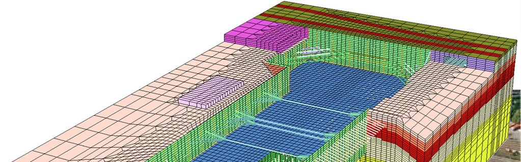
7 Final model as the result of optimal solution search


")

8 Initial design of support system (solution 1)
9 Solution 2 Reinforcement of the excavation bottom groundwater table ground level slurry wall soft soils bottom of excavation

10 Solution 2 Drilling of the jet-grouting columns groundwater table ground level slurry wall soft soils


11 Solution 2 Realization of the jet-grouting wall groundwater table ground level slurry wall soft soils
12 Solution 2 Jet-grouting wall composed of jet-grouting columns Ø 0.60m Ø 0.60 m
13 Setup for modified support system (solution 2)
14 Setup for modified support system (solution 3)
15 Selection of support system Comparison of wall displacements and settlements Preliminary optimization Solution n Wall displacement Differential Settlement Near RR settlement Long side RR tracks tracks tower [cm] [cm] [cm] [cm]
16 Optimization of selected support solution Models used in preliminary optimization Simplifications for computational speed Paneling in the retaining wall neglected Jet-grouting column walls modeled with elastic shells Jet-grouting column walls perfectly connected with the retaining wall Final model Improvements bringing closer to reality Specifying rotational hinges between diaphragm wall segments Elasto-plastic behavior Translational uncoupling widening of the jet-grouting walls local increase of anchor lengths


17 Introduction of translational uncoupling Preliminary model Final model Legend: - Compression + Tension Tension Tension Perfect connectionbetween diaphragm wall and jet-grouting wall Detachment of slurry wall allowed


 Excessive")

18 Accounting for hinges between diaphragm wall segments Preliminary model Final model M YY Y M YY 800kNm/m Rotational hinges M YY =0 Uncoupled translational d.o.f. ( f t =0 ) Excessive bending moments at construction joints between wall segments Elimination of spurious moments

19 Wall displacements obtained with the refined, final model 1.9cm 2.5cm Additional 2 nd row of prestressed struts 2.7cm 2.5cm


20 Deformed slurry wall segments and resulting settlements Retaining wall adjacent to railroad tracks Existing office building 0.9cm 0.1cm 0.1cm 0.1cm
21 Above-ground structure and piles for supporting vertical loads

 600mm L 16m 4.5cm 3.")
22 Structure settlements without and with piles Without piles 10.4cm 3.6cm Withpiles (screw drilled castin-place) 600mm L 16m 4.5cm 3.6cm


23 Prediction of settlements for the new structure Structure of new building Existing office building
24 Conclusions Detailed 3D finite element model valuable information for the design and optimization of the geotechnical structure Use of an appropriate constitutive law is of utmost importance for FE simulations of an excavation Model has allowed design choices to be made : Jet-grout column walls are necessary to limit horizontal displacements Pre-stressed struts are required to prevent mobilization of soil deformation Highlighting the need for piles that limit settlements of the new structure Local lengthening of anchors
25 Thank you for your attention! 2014