December 6, Nate Hatleback Project Manager City of Thornton 9500 Civic Center Drive Thornton, CO 80229
|
|
|
- Kristian Cross
- 5 years ago
- Views:
Transcription

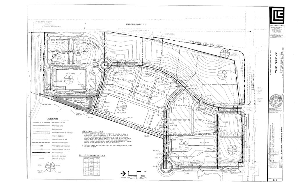
1 December 6, 2016 Nate Hatleback Project Manager City of Thornton 9500 Civic Center Drive Thornton, CO RE: Drainage Conformance Letter Hilton Garden The Grove The Grove Filing No 1, lot 5E Thornton, CO. Dear Mr. Hatleback, The Grove, Lot 5E is a 3.18 acre commercial hotel center located at The Grove in Thornton, Colorado. The site plan and general layout of Lot 5E is in conformance with the original site plan layout for The Grove project. This property will include a five-story structure, encompassing approximately 138,000 square feet with 122 guest rooms; 5,000 square foot restaurant and patio; and 4,000 square foot conference meeting facility. The storm water for Lot 5E will be directed to The Grove detention pond as described in the Drainage Report for The Grove, Thornton, Colorado and Dated March 8, 2013, prepared for Thornton Development, LLC by CLC Associates, Inc. See attached the Final Master Drainage map from the above referenced approved drainage report. This map shows the storm water for Lot 5E, Basin F, being conveyed to the detention pond in Basin B via a storm sewer system. See attached sheet from the above referenced report that describes the specific details of drainage Basins B & F. The entire project is within Basin F which is designated to be commercial buildings, drive aisles, parking spaces, and landscaped areas. In the original drainage report for The Grove, Basin F has a 5 year storm coefficient of 0.82 and 100 year storm coefficient of The proposed coefficients for the Hilton Garden Inn are 0.70 and 0.74 for the 5 and 100 year storm, respectively. The calculations for these coefficients are shown in this letter. These coefficients are less than the original planned coefficients and therefore less storm water will runoff the site than originally planned. The site is divided into drainage basins as shown on the attached drainage map and basin summary calculations. Basins A1, A2, A3, and A8 all drain off the site and will be conveyed to the detention pond via existing storm sewer system. Basins A4, A5 and A7 are collected by a 5ft Type R inlet within each basin and then conveyed to the existing storm sewer system via a new storm line to be installed. Basin A6 is the building roof which is conveyed from the roof to the existing storm sewer via proposed storm line. The attached inlet calculations show that there is sufficient capacity in the proposed and existing inlets for both the 5 and 100 year storm event. The drainage for the current site consists of 5 drainage basins with 4 of them draining into the existing inlets within the street and 1 basin running south off the property into the adjacent parcel. Calculations for the existing drainage and inlets are attached to this letter. The drainage improvements proposed with the construction of The Grove, Lot 5E is in conformance with the above referenced drainage report. Sincerely, Nick Sheremeta Point Consulting, LLC 8460 W Ken Caryl Avenue, Littleton Colorado,
2

3
4 Proposed Basin Summary Hilton The Grove Job Number: Basin Design Pt Area Area Tc Composite I - 5Yr Q -5Yr Composite I Yr Q- 100Yr Designation Designation (SF) (Acres) (Min) C(5Yr) (in/hr) (CFS) C (100 Yr) (in/hr) (CFS) A A A A A A A A Summation of Routed Flows Design Pt Contributing Q-5Yr Q-100 Yr Designation Basins (CFS) (Cfs) 1 A1+A A A3+A4+A5+A A A A4+A5+A A
5 Proposed Weighted Runoff Coefficients Calculated By: NWS Hilton The Grove Checked By: TDW Job Number: Date: Proposed C5 C2 C10 C100 IMP% Roof Concrete Drive/Walk Landscaping Paved Street Multi-family Commercial Gravel Land Use (Acres) Weighted Runoff Coefficient Total Concrete Paved Basin Area Roof Drive/Walk Landscape Street Multi-family Commercial Gravel C2 C5 C10 C100 %Imp A A A A A A A A TOTAL
6
7
8
9
10


11
12
13
14
15
16
17
18
19
20
21
22


23
24
25
26
27
28
29
30 Project: Inlet ID: ALLOWABLE CAPACITY FOR ONE-HALF OF STREET (Minor & Major Storm) (Based on Regulated Criteria for Maximum Allowable Flow Depth and Spread) Hilton The Grove Proposed Inlet For Area A5 Gutter Geometry (Enter data in the blue cells) Maximum Allowable Width for Spread Behind Curb T BACK = 0.0 ft Side Slope Behind Curb (leave blank for no conveyance credit behind curb) S BACK = ft/ft Manning's Roughness Behind Curb (typically between and 0.020) n BACK = Height of Curb at Gutter Flow Line H CURB = 6.00 inches Distance from Curb Face to Street Crown T CROWN = 2.0 ft Gutter Width W = 1.00 ft Street Transverse Slope S X = ft/ft Gutter Cross Slope (typically 2 inches over 24 inches or ft/ft) S W = ft/ft Street Longitudinal Slope - Enter 0 for sump condition S O = ft/ft Manning's Roughness for Street Section (typically between and 0.020) n STREET = Minor Storm Major Storm Max. Allowable Spread for Minor & Major Storm T MAX = ft Max. Allowable Depth at Gutter Flowline for Minor & Major Storm d MAX = inches Allow Flow Depth at Street Crown (leave blank for no) check = yes Maximum Capacity for 1/2 Street based On Allowable Spread Minor Storm Major Storm Water Depth without Gutter Depression (Eq. ST-2) y = inches Vertical Depth between Gutter Lip and Gutter Flowline (usually 2") d C = inches Gutter Depression (d C - (W * S x * 12)) a = inches Water Depth at Gutter Flowline d = inches Allowable Spread for Discharge outside the Gutter Section W (T - W) T X = ft Gutter Flow to Design Flow Ratio by FHWA HEC-22 method (Eq. ST-7) E O = Discharge outside the Gutter Section W, carried in Section T X Q X = cfs Discharge within the Gutter Section W (Q T - Q X) Q W = cfs Discharge Behind the Curb (e.g., sidewalk, driveways, & lawns) Q BACK = cfs Maximum Flow Based On Allowable Spread Q T = SUMP SUMP cfs Flow Velocity within the Gutter Section V = fps V*d Product: Flow Velocity times Gutter Flowline Depth V*d = Maximum Capacity for 1/2 Street based on Allowable Depth Minor Storm Major Storm Theoretical Water Spread T TH = ft Theoretical Spread for Discharge outside the Gutter Section W (T - W) T X TH = ft Gutter Flow to Design Flow Ratio by FHWA HEC-22 method (Eq. ST-7) E O = Theoretical Discharge outside the Gutter Section W, carried in Section T X TH Q X TH = cfs Actual Discharge outside the Gutter Section W, (limited by distance T CROWN) Q X = cfs Discharge within the Gutter Section W (Q d - Q X) Q W = cfs Discharge Behind the Curb (e.g., sidewalk, driveways, & lawns) Q BACK = cfs Total Discharge for Major & Minor Storm (Pre-Safety Factor) Q = cfs Average Flow Velocity Within the Gutter Section V = fps V*d Product: Flow Velocity Times Gutter Flowline Depth V*d = Slope-Based Depth Safety Reduction Factor for Major & Minor (d > 6") Storm R = SUMP SUMP Max Flow Based on Allowable Depth (Safety Factor Applied) Q d = SUMP SUMP cfs Resultant Flow Depth at Gutter Flowline (Safety Factor Applied) d = inches Resultant Flow Depth at Street Crown (Safety Factor Applied) d CROWN = inches MINOR STORM Allowable Capacity is based on Depth Criterion Minor Storm Major Storm MAJOR STORM Allowable Capacity is based on Depth Criterion Q allow = SUMP SUMP cfs Storm_inlet_Calculations 12_06_16.xlsm, Inlet 1 12/8/2016, 10:30 AM
31 INLET IN A SUMP OR SAG LOCATION H-Curb W W P H-Vert Lo (C) Wo Lo (G) Design Information (Input) MINOR MAJOR Type of Inlet CDOT Type R Curb Opening Type = CDOT Type R Curb Opening Local Depression (additional to continuous gutter depression 'a' from 'Q-Allow') a local = inches Number of Unit Inlets (Grate or Curb Opening) No = 1 1 Water Depth at Flowline (outside of local depression) Ponding Depth = inches Grate Information MINOR MAJOR Override Depths Length of a Unit Grate L o (G) = N/A N/A feet Width of a Unit Grate W o = N/A N/A feet Area Opening Ratio for a Grate (typical values ) A ratio = N/A N/A Clogging Factor for a Single Grate (typical value ) C f (G) = N/A N/A Grate Weir Coefficient (typical value ) C w (G) = N/A N/A Grate Orifice Coefficient (typical value ) C o (G) = N/A N/A Curb Opening Information MINOR MAJOR Length of a Unit Curb Opening L o (C) = feet Height of Vertical Curb Opening in Inches H vert = inches Height of Curb Orifice Throat in Inches H throat = inches Angle of Throat (see USDCM Figure ST-5) Theta = degrees Warning 1 Side Width for Depression Pan (typically the gutter width of 2 feet) W p = feet Clogging Factor for a Single Curb Opening (typical value 0.10) C f (C) = Curb Opening Weir Coefficient (typical value ) C w (C) = Curb Opening Orifice Coefficient (typical value ) C o (C) = Low Head Performance Reduction (Calculated) MINOR MAJOR Depth for Grate Midwidth d Grate = N/A N/A ft Depth for Curb Opening Weir Equation d Curb = ft Combination Inlet Performance Reduction Factor for Long Inlets RF Combination = Curb Opening Performance Reduction Factor for Long Inlets RF Curb = Grated Inlet Performance Reduction Factor for Long Inlets RF Grate = N/A N/A MINOR MAJOR Total Inlet Interception Capacity (assumes clogged condition) Q a = cfs Inlet Capacity IS GOOD for Minor and Major Storms(>Q PEAK) Q PEAK REQUIRED = cfs Warning 1: Dimension entered is not a typical dimension for inlet type specified. Storm_inlet_Calculations 12_06_16.xlsm, Inlet 1 12/8/2016, 10:30 AM
32 Project: Inlet ID: ALLOWABLE CAPACITY FOR ONE-HALF OF STREET (Minor & Major Storm) (Based on Regulated Criteria for Maximum Allowable Flow Depth and Spread) Hilton The Grove Proposed Inlet For Area A7 Gutter Geometry (Enter data in the blue cells) Maximum Allowable Width for Spread Behind Curb T BACK = 0.0 ft Side Slope Behind Curb (leave blank for no conveyance credit behind curb) S BACK = ft/ft Manning's Roughness Behind Curb (typically between and 0.020) n BACK = Height of Curb at Gutter Flow Line H CURB = 6.00 inches Distance from Curb Face to Street Crown T CROWN = 2.0 ft Gutter Width W = 1.00 ft Street Transverse Slope S X = ft/ft Gutter Cross Slope (typically 2 inches over 24 inches or ft/ft) S W = ft/ft Street Longitudinal Slope - Enter 0 for sump condition S O = ft/ft Manning's Roughness for Street Section (typically between and 0.020) n STREET = Minor Storm Major Storm Max. Allowable Spread for Minor & Major Storm T MAX = ft Max. Allowable Depth at Gutter Flowline for Minor & Major Storm d MAX = inches Allow Flow Depth at Street Crown (leave blank for no) check = yes Maximum Capacity for 1/2 Street based On Allowable Spread Minor Storm Major Storm Water Depth without Gutter Depression (Eq. ST-2) y = inches Vertical Depth between Gutter Lip and Gutter Flowline (usually 2") d C = inches Gutter Depression (d C - (W * S x * 12)) a = inches Water Depth at Gutter Flowline d = inches Allowable Spread for Discharge outside the Gutter Section W (T - W) T X = ft Gutter Flow to Design Flow Ratio by FHWA HEC-22 method (Eq. ST-7) E O = Discharge outside the Gutter Section W, carried in Section T X Q X = cfs Discharge within the Gutter Section W (Q T - Q X) Q W = cfs Discharge Behind the Curb (e.g., sidewalk, driveways, & lawns) Q BACK = cfs Maximum Flow Based On Allowable Spread Q T = SUMP SUMP cfs Flow Velocity within the Gutter Section V = fps V*d Product: Flow Velocity times Gutter Flowline Depth V*d = Maximum Capacity for 1/2 Street based on Allowable Depth Minor Storm Major Storm Theoretical Water Spread T TH = ft Theoretical Spread for Discharge outside the Gutter Section W (T - W) T X TH = ft Gutter Flow to Design Flow Ratio by FHWA HEC-22 method (Eq. ST-7) E O = Theoretical Discharge outside the Gutter Section W, carried in Section T X TH Q X TH = cfs Actual Discharge outside the Gutter Section W, (limited by distance T CROWN) Q X = cfs Discharge within the Gutter Section W (Q d - Q X) Q W = cfs Discharge Behind the Curb (e.g., sidewalk, driveways, & lawns) Q BACK = cfs Total Discharge for Major & Minor Storm (Pre-Safety Factor) Q = cfs Average Flow Velocity Within the Gutter Section V = fps V*d Product: Flow Velocity Times Gutter Flowline Depth V*d = Slope-Based Depth Safety Reduction Factor for Major & Minor (d > 6") Storm R = SUMP SUMP Max Flow Based on Allowable Depth (Safety Factor Applied) Q d = SUMP SUMP cfs Resultant Flow Depth at Gutter Flowline (Safety Factor Applied) d = inches Resultant Flow Depth at Street Crown (Safety Factor Applied) d CROWN = inches MINOR STORM Allowable Capacity is based on Depth Criterion Minor Storm Major Storm MAJOR STORM Allowable Capacity is based on Depth Criterion Q allow = SUMP SUMP cfs Storm_inlet_Calculations 12_06_16.xlsm, Inlet 2 12/8/2016, 10:39 AM
33 INLET IN A SUMP OR SAG LOCATION H-Curb W W P H-Vert Lo (C) Wo Lo (G) Design Information (Input) MINOR MAJOR Type of Inlet CDOT Type R Curb Opening Type = CDOT Type R Curb Opening Local Depression (additional to continuous gutter depression 'a' from 'Q-Allow') a local = inches Number of Unit Inlets (Grate or Curb Opening) No = 1 1 Water Depth at Flowline (outside of local depression) Ponding Depth = inches Grate Information MINOR MAJOR Override Depths Length of a Unit Grate L o (G) = N/A N/A feet Width of a Unit Grate W o = N/A N/A feet Area Opening Ratio for a Grate (typical values ) A ratio = N/A N/A Clogging Factor for a Single Grate (typical value ) C f (G) = N/A N/A Grate Weir Coefficient (typical value ) C w (G) = N/A N/A Grate Orifice Coefficient (typical value ) C o (G) = N/A N/A Curb Opening Information MINOR MAJOR Length of a Unit Curb Opening L o (C) = feet Height of Vertical Curb Opening in Inches H vert = inches Height of Curb Orifice Throat in Inches H throat = inches Angle of Throat (see USDCM Figure ST-5) Theta = degrees Warning 1 Side Width for Depression Pan (typically the gutter width of 2 feet) W p = feet Clogging Factor for a Single Curb Opening (typical value 0.10) C f (C) = Curb Opening Weir Coefficient (typical value ) C w (C) = Curb Opening Orifice Coefficient (typical value ) C o (C) = Low Head Performance Reduction (Calculated) MINOR MAJOR Depth for Grate Midwidth d Grate = N/A N/A ft Depth for Curb Opening Weir Equation d Curb = ft Combination Inlet Performance Reduction Factor for Long Inlets RF Combination = Curb Opening Performance Reduction Factor for Long Inlets RF Curb = Grated Inlet Performance Reduction Factor for Long Inlets RF Grate = N/A N/A MINOR MAJOR Total Inlet Interception Capacity (assumes clogged condition) Q a = cfs Inlet Capacity IS GOOD for Minor and Major Storms(>Q PEAK) Q PEAK REQUIRED = cfs Warning 1: Dimension entered is not a typical dimension for inlet type specified. Storm_inlet_Calculations 12_06_16.xlsm, Inlet 2 12/8/2016, 10:39 AM
34 Project: Inlet ID: ALLOWABLE CAPACITY FOR ONE-HALF OF STREET (Minor & Major Storm) (Based on Regulated Criteria for Maximum Allowable Flow Depth and Spread) Hilton The Grove Proposed Inlet For Area A4 Gutter Geometry (Enter data in the blue cells) Maximum Allowable Width for Spread Behind Curb T BACK = 0.0 ft Side Slope Behind Curb (leave blank for no conveyance credit behind curb) S BACK = ft/ft Manning's Roughness Behind Curb (typically between and 0.020) n BACK = Height of Curb at Gutter Flow Line H CURB = 6.00 inches Distance from Curb Face to Street Crown T CROWN = 2.0 ft Gutter Width W = 1.00 ft Street Transverse Slope S X = ft/ft Gutter Cross Slope (typically 2 inches over 24 inches or ft/ft) S W = ft/ft Street Longitudinal Slope - Enter 0 for sump condition S O = ft/ft Manning's Roughness for Street Section (typically between and 0.020) n STREET = Minor Storm Major Storm Max. Allowable Spread for Minor & Major Storm T MAX = ft Max. Allowable Depth at Gutter Flowline for Minor & Major Storm d MAX = inches Allow Flow Depth at Street Crown (leave blank for no) check = yes MINOR STORM Allowable Capacity is based on Depth Criterion Minor Storm Major Storm MAJOR STORM Allowable Capacity is based on Depth Criterion Q allow = SUMP SUMP cfs Storm_inlet_Calculations 12_06_16.xlsm, Area A4 Inlet 12/8/2016, 10:42 AM
35 INLET IN A SUMP OR SAG LOCATION H-Curb W W P H-Vert Lo (C) Wo Lo (G) Design Information (Input) MINOR MAJOR CDOT Type R Curb Opening Type of Inlet Type = CDOT Type R Curb Opening Local Depression (additional to continuous gutter depression 'a' from 'Q-Allow') a local = inches Number of Unit Inlets (Grate or Curb Opening) No = 1 1 Water Depth at Flowline (outside of local depression) Ponding Depth = inches Grate Information MINOR MAJOR Override Depths Length of a Unit Grate L o (G) = N/A N/A feet Width of a Unit Grate W o = N/A N/A feet Area Opening Ratio for a Grate (typical values ) A ratio = N/A N/A Clogging Factor for a Single Grate (typical value ) C f (G) = N/A N/A Grate Weir Coefficient (typical value ) C w (G) = N/A N/A Grate Orifice Coefficient (typical value ) C o (G) = N/A N/A Curb Opening Information MINOR MAJOR Length of a Unit Curb Opening L o (C) = feet Height of Vertical Curb Opening in Inches H vert = inches Height of Curb Orifice Throat in Inches H throat = inches Angle of Throat (see USDCM Figure ST-5) Theta = degrees Warning 1 Side Width for Depression Pan (typically the gutter width of 2 feet) W p = feet Clogging Factor for a Single Curb Opening (typical value 0.10) C f (C) = Curb Opening Weir Coefficient (typical value ) C w (C) = Curb Opening Orifice Coefficient (typical value ) C o (C) = Low Head Performance Reduction (Calculated) MINOR MAJOR Depth for Grate Midwidth d Grate = N/A N/A ft Depth for Curb Opening Weir Equation d Curb = ft Combination Inlet Performance Reduction Factor for Long Inlets RF Combination = Curb Opening Performance Reduction Factor for Long Inlets RF Curb = Grated Inlet Performance Reduction Factor for Long Inlets RF Grate = N/A N/A MINOR MAJOR Total Inlet Interception Capacity (assumes clogged condition) Q a = cfs Inlet Capacity IS GOOD for Minor and Major Storms(>Q PEAK) Q PEAK REQUIRED = cfs Warning 1: Dimension entered is not a typical dimension for inlet type specified. Storm_inlet_Calculations 12_06_16.xlsm, Area A4 Inlet 12/8/2016, 10:42 AM
36 A A % FDC WTR LINCOLN WAY 1 CANDLEWOOD SUITES WTR STM STM STM WTR WTR WTR STM STM MURPHY'S OIL & GAS GENERAL NOTE LEGEND 2.00% 1 GRADES SHOWN ARE FOR INFORMATION ONLY AND MAY BE ADJUSTED DURING THE CONSTRUCTION DOCUMENT REVIEW. BENCHMARK PROPERTY LINE EXISTING CONCRETE CURB PROPOSED CURB AND GUTTER PROPOSED CONTOUR EXISTING CONTOUR DRAINAGE SLOPE/FLOW ARROW PROPOSED DESIGN POINT BASIN BOUNDARY PROPOSED STORM SEWER EXISTING STORM LINE A1.1 DRAINAGE BASIN DESIGNATION YEAR RUNOFF COEFFICIENT YEAR RUNOFF COEFFICIENT AREA IN ACRES GPS DERIVED ELEVATIONS BASED ON NGS POINT 3 FEW, WITH A PUBLISHED ELEVATION OF FEET (NAVD88). BEING LOCATED IN THE SOUTHWEST QUADRANT OF SHERIDAN BLVD. AND 136TH AVE W KEN CARYL AVENUE LITTLETON, CO Point Consulting, LLC PLANNING ENGINEERING LANDSCAPE ARCHITECTURE LAND SURVEYING R % Know what's below. Callbefore you dig. A % FREDDY'S -1.56% -0.62% PROPOSED STORM INLET -0.51% HILTON GARDEN INN FFE= A FIRE PIT PATIO AREA A PROPOSED STORM PIPE A % PROPOSED STORM INLET -3.69% % A PROPOSED STORM INLET -5.69% LINCOLN WAY % A LOT AC LINCOLN STREET SS BASIN SUMMARY TABLE BASIN ACRES Design Point Q5 CFS Q100 CFS A A A A A A A A SUMMARY OF ROUTED FLOWS DESIGN POINT CONTRIBUTING BASINS Q5 CFS Q100 CFS 1 A1+A A A3+A4+A5+A A A A4+A5+A A N SCALE 1" = 30' 30 SITE CONSTRUCTION DOCUMENTS DATE DESCRIPTION HILTON 1ST CITY SUBMITTAL 2ND CITY SUBMITTAL THORNTON, COLORADO JOB NO DRAINAGE MAP SHEET 1/1
37 Existing Basin Summary Calculated By: NWS Hilton The Grove Checked By: TDW Job Number: Date: Basin Design Pt Area Area Tc Composite I - 5Yr Q -5Yr Composite I Yr Q- 100Yr C100A C5A Designation Designation (SF) (Acres) (Min) C(5Yr) (in/hr) (CFS) C (100 Yr) (in/hr) (CFS) H H H H H
38 Existing Weighted Runoff Coefficients Calculated By: NWS Hilton The Grove Checked By: TDW Job Number: Date: Proposed C5 C2 C10 C100 IMP% Roof Concrete Drive/Walk Landscaping Paved Street Multi-family Commercial Gravel Land Use (Acres) Weighted Runoff Coefficient Total Concrete Paved Basin Area Roof Drive/Walk Landscape Street Multi-family Commercial Gravel C2 C5 C10 C100 %Imp H H H H H TOTAL
39 Project: Inlet ID: ALLOWABLE CAPACITY FOR ONE-HALF OF STREET (Minor & Major Storm) (Based on Regulated Criteria for Maximum Allowable Flow Depth and Spread) Hilton The Grove Existing Inlet Basin H1 Gutter Geometry (Enter data in the blue cells) Maximum Allowable Width for Spread Behind Curb T BACK = 0.0 ft Side Slope Behind Curb (leave blank for no conveyance credit behind curb) S BACK = ft/ft Manning's Roughness Behind Curb (typically between and 0.020) n BACK = Height of Curb at Gutter Flow Line H CURB = 7.00 inches Distance from Curb Face to Street Crown T CROWN = 15.0 ft Gutter Width W = 2.00 ft Street Transverse Slope S X = ft/ft Gutter Cross Slope (typically 2 inches over 24 inches or ft/ft) S W = ft/ft Street Longitudinal Slope - Enter 0 for sump condition S O = ft/ft Manning's Roughness for Street Section (typically between and 0.020) n STREET = Minor Storm Major Storm Max. Allowable Spread for Minor & Major Storm T MAX = ft Max. Allowable Depth at Gutter Flowline for Minor & Major Storm d MAX = inches Allow Flow Depth at Street Crown (leave blank for no) check = yes Maximum Capacity for 1/2 Street based On Allowable Spread Minor Storm Major Storm Water Depth without Gutter Depression (Eq. ST-2) y = inches Vertical Depth between Gutter Lip and Gutter Flowline (usually 2") d C = inches Gutter Depression (d C - (W * S x * 12)) a = inches Water Depth at Gutter Flowline d = inches Allowable Spread for Discharge outside the Gutter Section W (T - W) T X = ft Gutter Flow to Design Flow Ratio by FHWA HEC-22 method (Eq. ST-7) E O = Discharge outside the Gutter Section W, carried in Section T X Q X = cfs Discharge within the Gutter Section W (Q T - Q X) Q W = cfs Discharge Behind the Curb (e.g., sidewalk, driveways, & lawns) Q BACK = cfs Maximum Flow Based On Allowable Spread Q T = cfs Flow Velocity within the Gutter Section V = fps V*d Product: Flow Velocity times Gutter Flowline Depth V*d = Maximum Capacity for 1/2 Street based on Allowable Depth Minor Storm Major Storm Theoretical Water Spread T TH = ft Theoretical Spread for Discharge outside the Gutter Section W (T - W) T X TH = ft Gutter Flow to Design Flow Ratio by FHWA HEC-22 method (Eq. ST-7) E O = Theoretical Discharge outside the Gutter Section W, carried in Section T X TH Q X TH = cfs Actual Discharge outside the Gutter Section W, (limited by distance T CROWN) Q X = cfs Discharge within the Gutter Section W (Q d - Q X) Q W = cfs Discharge Behind the Curb (e.g., sidewalk, driveways, & lawns) Q BACK = cfs Total Discharge for Major & Minor Storm (Pre-Safety Factor) Q = cfs Average Flow Velocity Within the Gutter Section V = fps V*d Product: Flow Velocity Times Gutter Flowline Depth V*d = Slope-Based Depth Safety Reduction Factor for Major & Minor (d > 6") Storm R = Max Flow Based on Allowable Depth (Safety Factor Applied) Q d = cfs Resultant Flow Depth at Gutter Flowline (Safety Factor Applied) d = inches Resultant Flow Depth at Street Crown (Safety Factor Applied) d CROWN = inches MINOR STORM Allowable Capacity is based on Spread Criterion Minor Storm Major Storm MAJOR STORM Allowable Capacity is based on Spread Criterion Q allow = cfs Minor storm max. allowable capacity GOOD - greater than the design flow given on sheet 'Inlet Management' Major storm max. allowable capacity GOOD - greater than the design flow given on sheet 'Inlet Management' Storm_inlet_Calculations 12_06_16.xlsm, Existing Inlet Basin A1 12/8/2016, 10:47 AM
40 INLET ON A CONTINUOUS GRADE Design Information (Input) MINOR MAJOR CDOT Type R Curb Opening Type of Inlet Type = CDOT Type R Curb Opening Local Depression (additional to continuous gutter depression 'a') a LOCAL = inches Total Number of Units in the Inlet (Grate or Curb Opening) No = 1 1 Length of a Single Unit Inlet (Grate or Curb Opening) L o = ft Width of a Unit Grate (cannot be greater than W, Gutter Width) W o = N/A N/A ft Clogging Factor for a Single Unit Grate (typical min. value = 0.5) C f-g = N/A N/A Clogging Factor for a Single Unit Curb Opening (typical min. value = 0.1) C f-c = Street Hydraulics: OK - Q < Allowable Street Capacity' MINOR MAJOR Design Discharge for Half of Street (from Sheet Inlet Management ) Q o = cfs Water Spread Width T = ft Water Depth at Flowline (outside of local depression) d = inches Water Depth at Street Crown (or at T MAX) d CROWN = inches Ratio of Gutter Flow to Design Flow E o = Discharge outside the Gutter Section W, carried in Section T x Q x = cfs Discharge within the Gutter Section W Q w = cfs Discharge Behind the Curb Face Q BACK = cfs Flow Area within the Gutter Section W A W = sq ft Velocity within the Gutter Section W V W = fps Water Depth for Design Condition d LOCAL = inches Grate Analysis (Calculated) MINOR MAJOR Total Length of Inlet Grate Opening L = N/A N/A ft Ratio of Grate Flow to Design Flow E o-grate = N/A N/A Under No-Clogging Condition MINOR MAJOR Minimum Velocity Where Grate Splash-Over Begins V o = N/A N/A fps Interception Rate of Frontal Flow R f = N/A N/A Interception Rate of Side Flow R x = N/A N/A Interception Capacity Q i = N/A N/A cfs Under Clogging Condition MINOR MAJOR Clogging Coefficient for Multiple-unit Grate Inlet GrateCoef = N/A N/A Clogging Factor for Multiple-unit Grate Inlet GrateClog = N/A N/A Effective (unclogged) Length of Multiple-unit Grate Inlet L e = N/A N/A ft Minimum Velocity Where Grate Splash-Over Begins V o = N/A N/A fps Interception Rate of Frontal Flow R f = N/A N/A Interception Rate of Side Flow R x = N/A N/A Actual Interception Capacity Q a = N/A N/A cfs Carry-Over Flow = Q o-q a (to be applied to curb opening or next d/s inlet) Q b = N/A N/A cfs Curb or Slotted Inlet Opening Analysis (Calculated) MINOR MAJOR Equivalent Slope S e (based on grate carry-over) S e = ft/ft Required Length L T to Have 100% Interception L T = ft Under No-Clogging Condition MINOR MAJOR Effective Length of Curb Opening or Slotted Inlet (minimum of L, L T) L = ft Interception Capacity Q i = cfs Under Clogging Condition MINOR MAJOR Clogging Coefficient CurbCoef = Clogging Factor for Multiple-unit Curb Opening or Slotted Inlet CurbClog = Effective (Unclogged) Length L e = ft Actual Interception Capacity Q a = cfs Carry-Over Flow = Q b(grate)-q a Q b = cfs Summary MINOR MAJOR Total Inlet Interception Capacity Q = cfs Total Inlet Carry-Over Flow (flow bypassing inlet) Q b = cfs Capture Percentage = Q a/q o = C% = % Storm_inlet_Calculations 12_06_16.xlsm, Existing Inlet Basin A1 12/8/2016, 10:47 AM
41 Project: Inlet ID: ALLOWABLE CAPACITY FOR ONE-HALF OF STREET (Minor & Major Storm) (Based on Regulated Criteria for Maximum Allowable Flow Depth and Spread) Hilton The Grove Existing Inlet Basin H2 Gutter Geometry (Enter data in the blue cells) Maximum Allowable Width for Spread Behind Curb T BACK = 0.0 ft Side Slope Behind Curb (leave blank for no conveyance credit behind curb) S BACK = ft/ft Manning's Roughness Behind Curb (typically between and 0.020) n BACK = Height of Curb at Gutter Flow Line H CURB = 7.00 inches Distance from Curb Face to Street Crown T CROWN = 15.0 ft Gutter Width W = 2.00 ft Street Transverse Slope S X = ft/ft Gutter Cross Slope (typically 2 inches over 24 inches or ft/ft) S W = ft/ft Street Longitudinal Slope - Enter 0 for sump condition S O = ft/ft Manning's Roughness for Street Section (typically between and 0.020) n STREET = Minor Storm Major Storm Max. Allowable Spread for Minor & Major Storm T MAX = ft Max. Allowable Depth at Gutter Flowline for Minor & Major Storm d MAX = inches Allow Flow Depth at Street Crown (leave blank for no) check = yes Maximum Capacity for 1/2 Street based On Allowable Spread Minor Storm Major Storm Water Depth without Gutter Depression (Eq. ST-2) y = inches Vertical Depth between Gutter Lip and Gutter Flowline (usually 2") d C = inches Gutter Depression (d C - (W * S x * 12)) a = inches Water Depth at Gutter Flowline d = inches Allowable Spread for Discharge outside the Gutter Section W (T - W) T X = ft Gutter Flow to Design Flow Ratio by FHWA HEC-22 method (Eq. ST-7) E O = Discharge outside the Gutter Section W, carried in Section T X Q X = cfs Discharge within the Gutter Section W (Q T - Q X) Q W = cfs Discharge Behind the Curb (e.g., sidewalk, driveways, & lawns) Q BACK = cfs Maximum Flow Based On Allowable Spread Q T = cfs Flow Velocity within the Gutter Section V = fps V*d Product: Flow Velocity times Gutter Flowline Depth V*d = Maximum Capacity for 1/2 Street based on Allowable Depth Minor Storm Major Storm Theoretical Water Spread T TH = ft Theoretical Spread for Discharge outside the Gutter Section W (T - W) T X TH = ft Gutter Flow to Design Flow Ratio by FHWA HEC-22 method (Eq. ST-7) E O = Theoretical Discharge outside the Gutter Section W, carried in Section T X TH Q X TH = cfs Actual Discharge outside the Gutter Section W, (limited by distance T CROWN) Q X = cfs Discharge within the Gutter Section W (Q d - Q X) Q W = cfs Discharge Behind the Curb (e.g., sidewalk, driveways, & lawns) Q BACK = cfs Total Discharge for Major & Minor Storm (Pre-Safety Factor) Q = cfs Average Flow Velocity Within the Gutter Section V = fps V*d Product: Flow Velocity Times Gutter Flowline Depth V*d = Slope-Based Depth Safety Reduction Factor for Major & Minor (d > 6") Storm R = Max Flow Based on Allowable Depth (Safety Factor Applied) Q d = cfs Resultant Flow Depth at Gutter Flowline (Safety Factor Applied) d = inches Resultant Flow Depth at Street Crown (Safety Factor Applied) d CROWN = inches MINOR STORM Allowable Capacity is based on Spread Criterion Minor Storm Major Storm MAJOR STORM Allowable Capacity is based on Spread Criterion Q allow = cfs Minor storm max. allowable capacity GOOD - greater than the design flow given on sheet 'Inlet Management' Major storm max. allowable capacity GOOD - greater than the design flow given on sheet 'Inlet Management' Storm_inlet_Calculations 12_06_16.xlsm, Existing Inlet Basin A2 12/8/2016, 10:50 AM
42 INLET ON A CONTINUOUS GRADE Design Information (Input) MINOR MAJOR CDOT Type R Curb Opening Type of Inlet Type = CDOT Type R Curb Opening Local Depression (additional to continuous gutter depression 'a') a LOCAL = inches Total Number of Units in the Inlet (Grate or Curb Opening) No = 1 1 Length of a Single Unit Inlet (Grate or Curb Opening) L o = ft Width of a Unit Grate (cannot be greater than W, Gutter Width) W o = N/A N/A ft Clogging Factor for a Single Unit Grate (typical min. value = 0.5) C f-g = N/A N/A Clogging Factor for a Single Unit Curb Opening (typical min. value = 0.1) C f-c = Street Hydraulics: OK - Q < Allowable Street Capacity' MINOR MAJOR Design Discharge for Half of Street (from Sheet Inlet Management ) Q o = cfs Water Spread Width T = ft Water Depth at Flowline (outside of local depression) d = inches Water Depth at Street Crown (or at T MAX) d CROWN = inches Ratio of Gutter Flow to Design Flow E o = Discharge outside the Gutter Section W, carried in Section T x Q x = cfs Discharge within the Gutter Section W Q w = cfs Discharge Behind the Curb Face Q BACK = cfs Flow Area within the Gutter Section W A W = sq ft Velocity within the Gutter Section W V W = fps Water Depth for Design Condition d LOCAL = inches Grate Analysis (Calculated) MINOR MAJOR Total Length of Inlet Grate Opening L = N/A N/A ft Ratio of Grate Flow to Design Flow E o-grate = N/A N/A Under No-Clogging Condition MINOR MAJOR Minimum Velocity Where Grate Splash-Over Begins V o = N/A N/A fps Interception Rate of Frontal Flow R f = N/A N/A Interception Rate of Side Flow R x = N/A N/A Interception Capacity Q i = N/A N/A cfs Under Clogging Condition MINOR MAJOR Clogging Coefficient for Multiple-unit Grate Inlet GrateCoef = N/A N/A Clogging Factor for Multiple-unit Grate Inlet GrateClog = N/A N/A Effective (unclogged) Length of Multiple-unit Grate Inlet L e = N/A N/A ft Minimum Velocity Where Grate Splash-Over Begins V o = N/A N/A fps Interception Rate of Frontal Flow R f = N/A N/A Interception Rate of Side Flow R x = N/A N/A Actual Interception Capacity Q a = N/A N/A cfs Carry-Over Flow = Q o-q a (to be applied to curb opening or next d/s inlet) Q b = N/A N/A cfs Curb or Slotted Inlet Opening Analysis (Calculated) MINOR MAJOR Equivalent Slope S e (based on grate carry-over) S e = ft/ft Required Length L T to Have 100% Interception L T = ft Under No-Clogging Condition MINOR MAJOR Effective Length of Curb Opening or Slotted Inlet (minimum of L, L T) L = ft Interception Capacity Q i = cfs Under Clogging Condition MINOR MAJOR Clogging Coefficient CurbCoef = Clogging Factor for Multiple-unit Curb Opening or Slotted Inlet CurbClog = Effective (Unclogged) Length L e = ft Actual Interception Capacity Q a = cfs Carry-Over Flow = Q b(grate)-q a Q b = cfs Summary MINOR MAJOR Total Inlet Interception Capacity Q = cfs Total Inlet Carry-Over Flow (flow bypassing inlet) Q b = cfs Capture Percentage = Q a/q o = C% = % Storm_inlet_Calculations 12_06_16.xlsm, Existing Inlet Basin A2 12/8/2016, 10:50 AM
43 Project: Inlet ID: ALLOWABLE CAPACITY FOR ONE-HALF OF STREET (Minor & Major Storm) (Based on Regulated Criteria for Maximum Allowable Flow Depth and Spread) Hilton The Grove Existing Inlet Basin H3 Gutter Geometry (Enter data in the blue cells) Maximum Allowable Width for Spread Behind Curb T BACK = 0.0 ft Side Slope Behind Curb (leave blank for no conveyance credit behind curb) S BACK = ft/ft Manning's Roughness Behind Curb (typically between and 0.020) n BACK = Height of Curb at Gutter Flow Line H CURB = 7.00 inches Distance from Curb Face to Street Crown T CROWN = 15.0 ft Gutter Width W = 2.00 ft Street Transverse Slope S X = ft/ft Gutter Cross Slope (typically 2 inches over 24 inches or ft/ft) S W = ft/ft Street Longitudinal Slope - Enter 0 for sump condition S O = ft/ft Manning's Roughness for Street Section (typically between and 0.020) n STREET = Minor Storm Major Storm Max. Allowable Spread for Minor & Major Storm T MAX = ft Max. Allowable Depth at Gutter Flowline for Minor & Major Storm d MAX = inches Allow Flow Depth at Street Crown (leave blank for no) check = yes Maximum Capacity for 1/2 Street based On Allowable Spread Minor Storm Major Storm Water Depth without Gutter Depression (Eq. ST-2) y = inches Vertical Depth between Gutter Lip and Gutter Flowline (usually 2") d C = inches Gutter Depression (d C - (W * S x * 12)) a = inches Water Depth at Gutter Flowline d = inches Allowable Spread for Discharge outside the Gutter Section W (T - W) T X = ft Gutter Flow to Design Flow Ratio by FHWA HEC-22 method (Eq. ST-7) E O = Discharge outside the Gutter Section W, carried in Section T X Q X = cfs Discharge within the Gutter Section W (Q T - Q X) Q W = cfs Discharge Behind the Curb (e.g., sidewalk, driveways, & lawns) Q BACK = cfs Maximum Flow Based On Allowable Spread Q T = cfs Flow Velocity within the Gutter Section V = fps V*d Product: Flow Velocity times Gutter Flowline Depth V*d = Maximum Capacity for 1/2 Street based on Allowable Depth Minor Storm Major Storm Theoretical Water Spread T TH = ft Theoretical Spread for Discharge outside the Gutter Section W (T - W) T X TH = ft Gutter Flow to Design Flow Ratio by FHWA HEC-22 method (Eq. ST-7) E O = Theoretical Discharge outside the Gutter Section W, carried in Section T X TH Q X TH = cfs Actual Discharge outside the Gutter Section W, (limited by distance T CROWN) Q X = cfs Discharge within the Gutter Section W (Q d - Q X) Q W = cfs Discharge Behind the Curb (e.g., sidewalk, driveways, & lawns) Q BACK = cfs Total Discharge for Major & Minor Storm (Pre-Safety Factor) Q = cfs Average Flow Velocity Within the Gutter Section V = fps V*d Product: Flow Velocity Times Gutter Flowline Depth V*d = Slope-Based Depth Safety Reduction Factor for Major & Minor (d > 6") Storm R = Max Flow Based on Allowable Depth (Safety Factor Applied) Q d = cfs Resultant Flow Depth at Gutter Flowline (Safety Factor Applied) d = inches Resultant Flow Depth at Street Crown (Safety Factor Applied) d CROWN = inches MINOR STORM Allowable Capacity is based on Spread Criterion Minor Storm Major Storm MAJOR STORM Allowable Capacity is based on Spread Criterion Q allow = cfs Minor storm max. allowable capacity GOOD - greater than the design flow given on sheet 'Inlet Management' Major storm max. allowable capacity GOOD - greater than the design flow given on sheet 'Inlet Management' Storm_inlet_Calculations 12_06_16.xlsm, Existing Inlet Basin A3 12/8/2016, 10:51 AM
44 INLET ON A CONTINUOUS GRADE Design Information (Input) MINOR MAJOR CDOT Type R Curb Opening Type of Inlet Type = CDOT Type R Curb Opening Local Depression (additional to continuous gutter depression 'a') a LOCAL = inches Total Number of Units in the Inlet (Grate or Curb Opening) No = 1 1 Length of a Single Unit Inlet (Grate or Curb Opening) L o = ft Width of a Unit Grate (cannot be greater than W, Gutter Width) W o = N/A N/A ft Clogging Factor for a Single Unit Grate (typical min. value = 0.5) C f-g = N/A N/A Clogging Factor for a Single Unit Curb Opening (typical min. value = 0.1) C f-c = Street Hydraulics: OK - Q < Allowable Street Capacity' MINOR MAJOR Design Discharge for Half of Street (from Sheet Inlet Management ) Q o = cfs Water Spread Width T = ft Water Depth at Flowline (outside of local depression) d = inches Water Depth at Street Crown (or at T MAX) d CROWN = inches Ratio of Gutter Flow to Design Flow E o = Discharge outside the Gutter Section W, carried in Section T x Q x = cfs Discharge within the Gutter Section W Q w = cfs Discharge Behind the Curb Face Q BACK = cfs Flow Area within the Gutter Section W A W = sq ft Velocity within the Gutter Section W V W = fps Water Depth for Design Condition d LOCAL = inches Grate Analysis (Calculated) MINOR MAJOR Total Length of Inlet Grate Opening L = N/A N/A ft Ratio of Grate Flow to Design Flow E o-grate = N/A N/A Under No-Clogging Condition MINOR MAJOR Minimum Velocity Where Grate Splash-Over Begins V o = N/A N/A fps Interception Rate of Frontal Flow R f = N/A N/A Interception Rate of Side Flow R x = N/A N/A Interception Capacity Q i = N/A N/A cfs Under Clogging Condition MINOR MAJOR Clogging Coefficient for Multiple-unit Grate Inlet GrateCoef = N/A N/A Clogging Factor for Multiple-unit Grate Inlet GrateClog = N/A N/A Effective (unclogged) Length of Multiple-unit Grate Inlet L e = N/A N/A ft Minimum Velocity Where Grate Splash-Over Begins V o = N/A N/A fps Interception Rate of Frontal Flow R f = N/A N/A Interception Rate of Side Flow R x = N/A N/A Actual Interception Capacity Q a = N/A N/A cfs Carry-Over Flow = Q o-q a (to be applied to curb opening or next d/s inlet) Q b = N/A N/A cfs Curb or Slotted Inlet Opening Analysis (Calculated) MINOR MAJOR Equivalent Slope S e (based on grate carry-over) S e = ft/ft Required Length L T to Have 100% Interception L T = ft Under No-Clogging Condition MINOR MAJOR Effective Length of Curb Opening or Slotted Inlet (minimum of L, L T) L = ft Interception Capacity Q i = cfs Under Clogging Condition MINOR MAJOR Clogging Coefficient CurbCoef = Clogging Factor for Multiple-unit Curb Opening or Slotted Inlet CurbClog = Effective (Unclogged) Length L e = ft Actual Interception Capacity Q a = cfs Carry-Over Flow = Q b(grate)-q a Q b = cfs Summary MINOR MAJOR Total Inlet Interception Capacity Q = cfs Total Inlet Carry-Over Flow (flow bypassing inlet) Q b = cfs Capture Percentage = Q a/q o = C% = % Storm_inlet_Calculations 12_06_16.xlsm, Existing Inlet Basin A3 12/8/2016, 10:51 AM
45 Project: Inlet ID: ALLOWABLE CAPACITY FOR ONE-HALF OF STREET (Minor & Major Storm) (Based on Regulated Criteria for Maximum Allowable Flow Depth and Spread) Hilton The Grove Existing Inlet Basin H5 Gutter Geometry (Enter data in the blue cells) Maximum Allowable Width for Spread Behind Curb T BACK = 0.0 ft Side Slope Behind Curb (leave blank for no conveyance credit behind curb) S BACK = ft/ft Manning's Roughness Behind Curb (typically between and 0.020) n BACK = Height of Curb at Gutter Flow Line H CURB = 7.00 inches Distance from Curb Face to Street Crown T CROWN = 15.0 ft Gutter Width W = 2.00 ft Street Transverse Slope S X = ft/ft Gutter Cross Slope (typically 2 inches over 24 inches or ft/ft) S W = ft/ft Street Longitudinal Slope - Enter 0 for sump condition S O = ft/ft Manning's Roughness for Street Section (typically between and 0.020) n STREET = Minor Storm Major Storm Max. Allowable Spread for Minor & Major Storm T MAX = ft Max. Allowable Depth at Gutter Flowline for Minor & Major Storm d MAX = inches Allow Flow Depth at Street Crown (leave blank for no) check = yes Maximum Capacity for 1/2 Street based On Allowable Spread Minor Storm Major Storm Water Depth without Gutter Depression (Eq. ST-2) y = inches Vertical Depth between Gutter Lip and Gutter Flowline (usually 2") d C = inches Gutter Depression (d C - (W * S x * 12)) a = inches Water Depth at Gutter Flowline d = inches Allowable Spread for Discharge outside the Gutter Section W (T - W) T X = ft Gutter Flow to Design Flow Ratio by FHWA HEC-22 method (Eq. ST-7) E O = Discharge outside the Gutter Section W, carried in Section T X Q X = cfs Discharge within the Gutter Section W (Q T - Q X) Q W = cfs Discharge Behind the Curb (e.g., sidewalk, driveways, & lawns) Q BACK = cfs Maximum Flow Based On Allowable Spread Q T = cfs Flow Velocity within the Gutter Section V = fps V*d Product: Flow Velocity times Gutter Flowline Depth V*d = Maximum Capacity for 1/2 Street based on Allowable Depth Minor Storm Major Storm Theoretical Water Spread T TH = ft Theoretical Spread for Discharge outside the Gutter Section W (T - W) T X TH = ft Gutter Flow to Design Flow Ratio by FHWA HEC-22 method (Eq. ST-7) E O = Theoretical Discharge outside the Gutter Section W, carried in Section T X TH Q X TH = cfs Actual Discharge outside the Gutter Section W, (limited by distance T CROWN) Q X = cfs Discharge within the Gutter Section W (Q d - Q X) Q W = cfs Discharge Behind the Curb (e.g., sidewalk, driveways, & lawns) Q BACK = cfs Total Discharge for Major & Minor Storm (Pre-Safety Factor) Q = cfs Average Flow Velocity Within the Gutter Section V = fps V*d Product: Flow Velocity Times Gutter Flowline Depth V*d = Slope-Based Depth Safety Reduction Factor for Major & Minor (d > 6") Storm R = Max Flow Based on Allowable Depth (Safety Factor Applied) Q d = cfs Resultant Flow Depth at Gutter Flowline (Safety Factor Applied) d = inches Resultant Flow Depth at Street Crown (Safety Factor Applied) d CROWN = inches MINOR STORM Allowable Capacity is based on Spread Criterion Minor Storm Major Storm MAJOR STORM Allowable Capacity is based on Spread Criterion Q allow = cfs Minor storm max. allowable capacity GOOD - greater than the design flow given on sheet 'Inlet Management' Major storm max. allowable capacity GOOD - greater than the design flow given on sheet 'Inlet Management' Storm_inlet_Calculations 12_06_16.xlsm, Existing Inlet Basin A8 12/8/2016, 10:52 AM
46 INLET ON A CONTINUOUS GRADE Design Information (Input) MINOR MAJOR CDOT Type R Curb Opening Type of Inlet Type = CDOT Type R Curb Opening Local Depression (additional to continuous gutter depression 'a') a LOCAL = inches Total Number of Units in the Inlet (Grate or Curb Opening) No = 1 1 Length of a Single Unit Inlet (Grate or Curb Opening) L o = ft Width of a Unit Grate (cannot be greater than W, Gutter Width) W o = N/A N/A ft Clogging Factor for a Single Unit Grate (typical min. value = 0.5) C f-g = N/A N/A Clogging Factor for a Single Unit Curb Opening (typical min. value = 0.1) C f-c = Street Hydraulics: OK - Q < Allowable Street Capacity' MINOR MAJOR Design Discharge for Half of Street (from Sheet Inlet Management ) Q o = cfs Water Spread Width T = ft Water Depth at Flowline (outside of local depression) d = inches Water Depth at Street Crown (or at T MAX) d CROWN = inches Ratio of Gutter Flow to Design Flow E o = Discharge outside the Gutter Section W, carried in Section T x Q x = cfs Discharge within the Gutter Section W Q w = cfs Discharge Behind the Curb Face Q BACK = cfs Flow Area within the Gutter Section W A W = sq ft Velocity within the Gutter Section W V W = fps Water Depth for Design Condition d LOCAL = inches Grate Analysis (Calculated) MINOR MAJOR Total Length of Inlet Grate Opening L = N/A N/A ft Ratio of Grate Flow to Design Flow E o-grate = N/A N/A Under No-Clogging Condition MINOR MAJOR Minimum Velocity Where Grate Splash-Over Begins V o = N/A N/A fps Interception Rate of Frontal Flow R f = N/A N/A Interception Rate of Side Flow R x = N/A N/A Interception Capacity Q i = N/A N/A cfs Under Clogging Condition MINOR MAJOR Clogging Coefficient for Multiple-unit Grate Inlet GrateCoef = N/A N/A Clogging Factor for Multiple-unit Grate Inlet GrateClog = N/A N/A Effective (unclogged) Length of Multiple-unit Grate Inlet L e = N/A N/A ft Minimum Velocity Where Grate Splash-Over Begins V o = N/A N/A fps Interception Rate of Frontal Flow R f = N/A N/A Interception Rate of Side Flow R x = N/A N/A Actual Interception Capacity Q a = N/A N/A cfs Carry-Over Flow = Q o-q a (to be applied to curb opening or next d/s inlet) Q b = N/A N/A cfs Curb or Slotted Inlet Opening Analysis (Calculated) MINOR MAJOR Equivalent Slope S e (based on grate carry-over) S e = ft/ft Required Length L T to Have 100% Interception L T = ft Under No-Clogging Condition MINOR MAJOR Effective Length of Curb Opening or Slotted Inlet (minimum of L, L T) L = ft Interception Capacity Q i = cfs Under Clogging Condition MINOR MAJOR Clogging Coefficient CurbCoef = Clogging Factor for Multiple-unit Curb Opening or Slotted Inlet CurbClog = Effective (Unclogged) Length L e = ft Actual Interception Capacity Q a = cfs Carry-Over Flow = Q b(grate)-q a Q b = cfs Summary MINOR MAJOR Total Inlet Interception Capacity Q = cfs Total Inlet Carry-Over Flow (flow bypassing inlet) Q b = cfs Capture Percentage = Q a/q o = C% = % Storm_inlet_Calculations 12_06_16.xlsm, Existing Inlet Basin A8 12/8/2016, 10:52 AM