Current Situation of MSR Development in Japan. Yoichiro SHIMAZU Graduate School of Engineering Hokkaido University, Japan
|
|
|
- Dorthy Briggs
- 5 years ago
- Views:
Transcription

1 Current Situation of MSR Development in Japan Yoichiro SHIMAZU Graduate School of Engineering Hokkaido University, Japan 1
2 Related Organizations International Thorium Molten-Salt Forum (ITHMSF ) President: Dr. Kazuo FURUKAWA and staffs (Drs. Yoshio KATO, Ritsuo YOSHIOKA, etc.) Toyohashi University of Technology (TUT) Laboratory of Prof. Koshi MITACHI Hokkaido University (HU) Laboratory of Prof. Yoichiro SHIMAZU Kyoto University (KU) - Ass. Prof. Takashi KAMEI of Institute of Sustainability Science Tohoku University, Osaka university, Tokyo Institute of Technology In total, more than 10 scientists are related to MSR research, except foreign coworkers. 2


3 Basic Strategy of the MSR Group Activity Logistic Function Global Future Energy Prediction We need a rapid increase of nuclear energy with a doubling-time of 10 years. 3
4 Other Requirements for Nuclear Energy 1) Simplicity (structure, operation, maintenance etc.) 2) Excellent Safety (No severe accident) 3) Flexibility in plant size (small to large plant) 4) Nuclear proliferation resistance 5) Economy 6) Flexibility in fuel cycle Th resource: 3-4 times more abundant than U Utilization/Incineration capability of Pu Incineration capability of Minor Actinides, F.P. One of the best solution is Thorium-Cycle with Molten Salt Fuel 4
5 Research Areas ITHMSF: Developmental Strategy of THORIMS- NES composed of MSR : FUJI and Accelerator Molten Salt Breeder : AMSB Toyohashi U.: Thermal and hydraulics analysis and Nuclear design for good breeding capability Hokkaido U.: Pu-Th fuel cycle in both thermal and fast MSRs and transient analyses Kyoto U.: General investigation of Th usage in view of sustainability 5
6 Financial support In the present, there are no financial support from the governmental. (Having proposed developmental projects for governmental supports without success.) Our basic strategy is to depend on the commercial activity, and to search the financial support of International Industry group under the cooperation with the entrepreneurs' group. No experiments nor system design have been done in these decades. 6
7 Recent publications-1 ITHMSF TUT K. Furukawa et. al., Molten-Salt Reactor FUJI, in Status of Small Reactor Designs Without On-Site Refueling IAEA TECDOC-1536(2007). K. Furukawa et. al., A Road Map for the Realization of Global-scale Thorium Breeding Fuel Cycle by Single Molten-Fluoride Flow, Energy Conversion and Management, in print (2008), written by 17 coauthors in the world. K. Mitachi et al. Self-sustaining Core Design for 200 MWe Molten-Salt Reactor with Thorium-Uranium Fuel FUJI-U3-(0) International Workshop on Thorium Utilization for Sustainable Development of Nuclear Energy, TU ,Beijing, (2007) Three-region Core Design for 200-MWe Molten-Salt Reactor with Thorium-Uranium Fuel Nuclear Technology, vol.158,no.3,pp348-pp357(2007) KU K. Furukawa Y.Kato T.Kamei Developmental Strategy of THORIMS- NES consisted of Th-MSR FUJI and AMSB, IAEA- TU2007, Beijing, (2007) Statement from the Experts Meeting on Low Carbon Society Scenarios 2050 and the Roles of China, India and Japan, Kyoto, Japan, (2007). 7
8 Recent publications-2 HU N.Suzuki, Y.Shimazu, Preliminary Safety Analysis on Depressurization Accident of a Molten Salt Reactor without Scram, J.Nucl.Sci.Technol,Vol43,No.7,pp ,2006 Y.Homma, Y. Shimazu, T.Narabayashi, Flattening of Fast Neutron Flux Distribution in Molten Salt Reactor for Longer Grahpite Moderator lifetime, Proceedings, PBNC2006, Sydney, CDROM(2006) Y. Shimazu, N. Suzuki, Reactivity Initiated Accident Analysis of a Molten Salt Reactor, Proc. ICENES2007, CD-ROM(2007) Y. Honma et al, Fuel Cycle Study on Pu-Th based Molten Salt Reactors for Sustainable Fuel Supply, TU , Beijing, (2007) 8
9 FUJI-U3 Core Design (Three region core concept) Vessel Reflector (0.005) Core2 (0.27) Core1 (0.39) Core3 (0.45) Fuel Path (0.9) ( ) is Fuel/Graphite volume ratio. z r Unit:[cm]
10 FUJI-U3 3-region Core Concept K Lower K-infinity by higher Fuel/Graphite ratio, due to lesser neutron moderation. Fuel/Graphite ratio 1) Flux flattening by high F/G ratio(core1) and low F/G ratio(core2). 2) Reducing neutron leakage by high F/G ratio(core3). Core1 Core2 Core3 Fuel/Graphite volume ratio
11 FUJI-U3 Design Conclusion Assuming 75% capacity factor and chemical processing interval of 7.5 years, 1) Conversion Ratio = 1.0 (for 30 years average) Self sustaining reactor 2) No graphite replacement for 30 years. 3) Scaling FUJI (250 MWe) to 1 GWe plant, and compare with 1 GWe BWR. For 30 years total: Fissile requirement Pu production MA (Np/Am/Cm) production FUJI-U3 (1GWe) 7.8 t ( ) 4 kg 23 kg Relative to 1GWe BWR 32% 0.1% 4 % Since CR is 1.0, the above 7.8 t fissile is discharged at the end of reactor life, and it can be used to the next reactor. 11
12 FUJI-U3 Core Parameters Electric output Thermal output Thermal efficiency Reactor vessel Diameter/Height Core Diameter/Height Structural material Fuel salt composition mol % Conversion ratio (mean value) Temperature coefficient (dk/k) 200 MWe 450 MWth 44.4% 5.40 m/5.34 m 4.72 m/4.66m Modified Hastelloy-N LiF-BeF 2 -ThF UF , 16, 12, 0.24(initial) /K (average) Published at International Workshop on Thorium Utilization for Sustainable Development of Nuclear Energy, Beijing, 2007/12. 12
13 Fuel duct Reflector Vessel r 220cm Core 1 Core2 z 240cm 60cm 50cm FUJI-U2 ( Two region core) 13
14 Φ fast (n/cm 2 s) Results of the calculation of 233 U-MSR MSR1 fuji-u3 MSR-2R-U3 FUJI-U1 : 1-Region Core Irradiation limits of graphite moderators for 30 years operation FUJI-U2 : 2-Region Core (PBNC2006) FUJI-U3 : 3-Region Core (GLOBAL 2005) Moderator life (years) r (mesh) FUJI-U FUJI-U FUJI-U Center Core Reflector Radial distribution of fast neutron flux greater than 52keV 14
15 Results of the calculation of Pu-MSR Φ fast (n/cm 2 s) Maxφ fast (n/cm 2 s) 6e+013 5e+013 4e+013 FUJI-Pu1 FUJI-Pu1 FUJI-Pu2 :1-Region Core Irradiation limits of graphite moderators for 30 years operation 3e+013 2e+013 1e Center FUJI-Pu2 :2-Region Core (COE2006) Core R (mesh) Reflector Moderator life (years) r (mesh) FUJI-Pu FUJI-Pu Radial distribution of fast neutron flux greater than 52keV 15
16 1 Neutronic design Major R&D Concerns No significant concerns about reactor physics model. But, nuclear cross-section measurements for isotopes of the 233 U-Th cycle and the corresponding integral experiments are necessary. 2 3 Fuel chemistry Structural materials (Modified Hastelloy-N) No serious problems. But, the examination of detailed PuF 3 solubility data in relation to other fission product ions is necessary. Endurance tests should be performed in the minifuji pilot plant. The problem of Te attack could be solved by modified Hastelloy-N (1-2% Nb added), and redox potential control. 4 Core graphite Irradiation tests should be performed using a powerful reactor such as the MS-4 in Russia. Further development to improve radiation growth of graphite is preferable. 16
17 THORIMS-NES (1/2) THORIum Molten-Salt Nuclear Energy Synergetic System Basic Concept depends on three principles: [I] Thorium utilization [II] Application of Molten-Fluoride Fuel technology [III] Separation of Fissile-Producing Accelerator Breeders (AMSB) with chemical process plant & Power Generating Fission-Reactors (FUJI) 17
18 THORIMS-NES (2/2) Regional Center [Breeding & Chemical Processing Center] LWR Spent fuel Target salt* Dry Process. Plant 233 UF4 AMSB AMSB AMSB ( 4 30 breeders) ThF 4 Fertile salt** 7 LiF BeF 2 Chemical Process Plant (2 plants) (F.P.) Radio waste Plant ( 1 plant ) heavily safeguarded Dirty fuel salt Supplying# fuel salt very small MSR [mini.fuji] small MSR [FUJI] small MSR [FUJI] large MSR (in total TWe) Solid Fuel Cycle System Simple Molten Salt Fuel Cycle (*) 7 LiF BeF 2 ThF UF4 (**) 7 LiF BeF 2 ThF 4 (#)target salt* + additive 233 UF4 18
19 Accelerator Molten-Salt Breeder: AMSB Composed of three parts: 1GeV and ma proton accelerator Single-fluid molten fluoride target/blanket system Heat transfer and electric power recovery system sub-critical no radiation damage easy heat removal no target/blanket shuffling gas-curtain window multi-beam funneling available simpler chemical aspects 19

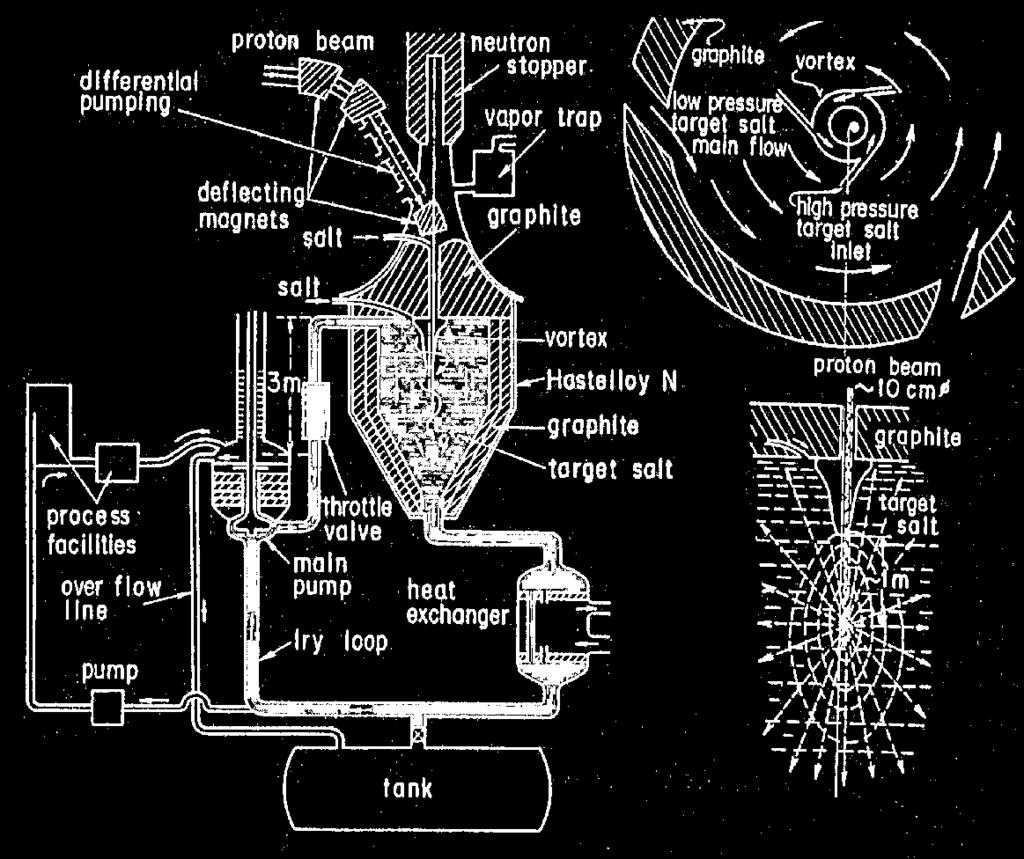
20 AMSB Concept 20
21 Developmental Strategy of THORIMS-NES 1) Installation/Operation of minifuji (7-10 MWe) : 7 years later 2) Installation/Operation of FUJI-Pu ( MWe) : 12 years later Pu from the existing spent-fuels : using and eliminating Pu Depending on such MSR-technology development, 3) Development and Installation of AMSB : years later 21
22 Deployment Plans of THORIMS-NES F-plan: Fission reactor development: minifuji and FUJI in several versions. FUJI power stations of smaller as well as larger size D-plan: Dry-processing of spent fuel salt and target/blanket salts Pu including fuel salt preparation from spent solid fuels of ordinary reactors such as LWR, FBR, HWR etc. A-plan: Accelerator Molten-Salt Breeder (AMSB) development Experimental, Prototype, & commercial facilities Regional Centers Deployment plan: Chemical processing & Radio-waste management plants 22
23 Developmental Schedule of THORIMS-NES INITIAL STAGE PROGRAM 3 rd year 7 th year 11 th year General R & D Fuel-salt loop Coolant-salt loop Electric generating test loop (200K We) Integral test loop (2M We) Materials (salts, alloy, graphite) Components & Instruments F1. Pilot-plant (minifuji-pu) Reactor design Reactor mock-up Reactor remote maintenance Reactor construction & operation construction operation D1. modified FREGATE D2. Chemical Processing of Fuel Salts MIDDLE TERM PROGRAM F2. Small Molten-Salt Power Station (FUJI-Pu) Reactor design Reactor mock-up Reactor remote maintenance Reactor construction & operation LONG TERM PROGRAM F3. Medium-,, and Large-Molten-Salt Power Stations A. Fissile Producing Breeder Development (AMSB, AMSB-Pu) Preliminary R & D Integral experimental facility (5mA proton beam) Prototype facility (50mA proton beam) Establishment of Thorium Molten-Salt Nuclear Energy Synergetics System design study design construction low power high power design study design construction 23
24 Future Plan ITHM SF: TUT HU International cooperation with Russia, USA, Europe and other countries. Participation in GIF (Generation IV International Forum) Control capability study for MSF-FUJI. Fuel cycle optimization for Pu and MA burning KU Scenario study of energy supply-demand balance at the time of the global use of thorium and a fossil fuel reduction. Scenario study of a smooth shift from the present uranium-lwrs to thorium-msrs. Safeguard of thorium usage in the countries except the nuclear weapon holders. Strategic competition of thorium usage with the uranium promotion countries (France, Russia etc.) Design of best mixture of energy technologies including thorium nuclear power and renewable energy accepted local circumstances. 24
25 Conclusion 1) MSR-FUJI in THORIMS-NES has Excellent Safety / Flexibility in plant size / Nuclear proliferation resistance / Good economy / Flexibility in fuel cycle (Incineration capability of Plutonium and Minor Actinides). 2) Although our activities are based on private and voluntary basis, analytical investigations are being carried out step by step, aiming an early-stage hugesize commercialization of Thorium Energy Industry. 25