Hydrogen refuelling station Linde s technologies
|
|
|
- Erin Bradley
- 5 years ago
- Views:
Transcription
1 Hydrogen refuelling station Linde s technologies Marek Gorecki 25 October 2018
2 1. The Linde Group introduction The Linde Group is one of the world leading concerns producing and distributing gases and gas technologies, as well as constructing industrial installations. It employs ca. 52 thousand employees and operates in ca. 100 countries worldwide. The concern has a over century-long tradition. The Linde Group comprises three divisions: Gases and Engineering (the two core divisions) and Other Activities. The largest division is Gases. The Linde Group Gases Division Engineering Division Other Activities Linde Gaz Polska has been present in Poland since 1993 and still is one of the leading companies in the market, offering complex solutions for gas deliveries and gas technologies. The headquarters is located in Cracow and the production facilities are spread over Poland. 2
3 2.1 Introduction to hydrogen refuelling station The Linde Group- as a world-leading hydrogen plant engineering company- is one of the driving forces behind the advancement of hydrogen production, distribution and fuelling technologies for mobility applications. The Linde Group participates in many hydrogen projects and initiatives on hydrogen mobility matured markets. Our technologies use in hydrogen infrastructure are patented. Every station is extensively tested before delivery. Delivery time is months. 3
4 2.1 Introduction to hydrogen refuelling station Key elements of hydrogen fuelling station 4

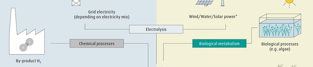
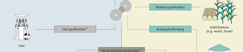
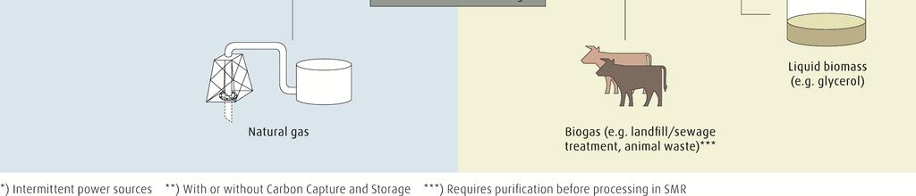
5 2.2 Hydrogen production processes 5
6 2.2 Hydrogen production processes Conventional through steam reforming of fossil fuels such as natural gas. Renewable such as biogenous processes or electrolysis of water with wind power, water power or solar energy. Though hydrogen as fuel creates no emissions at the tailpipe, the production of hydrogen still generates carbon dioxide(co2). The highest CO2 reduction can be reached by using renewable energies such as wind power, water power, solar energy and biomass. Definition of green hydrogen has to be determined. Hydrogen quality standards(as vehicles fuel) are currently under development in SAE International(e.g., SAE J2719 Hydrogen Specification Guideline for Fuel Cell Vehicles ) and in ASTM International. 6
7 2.3 Hydrogen distribution and storage pathways 7


8 2.3 Hydrogen storage and distribution pathways The methods of hydrogen distribution and storage are closely interconnected. The main hydrogen distribution concepts based on gaseous and liquid storage systems are CGH2/LH2 trailers road transport. - Compressed Gaseous Hydrogen (CGH2)is stored in pressure-tight containers like cylinders, cylinder bundles, tanks, pipes. - Cryogenic Liquid Hydrogen (LH2)is stored in specially insulated LH2 tanks, at minus 253 deg C. 8
9 2.3 Hydrogen distribution and storage pathways On-site production- as an alternative to producing hydrogen at one place and then delivering it to the hydrogen fuelling station. Hydrogen is produced and stored directly at the hydrogen fuelling station, eliminating the cost and effort of hydrogen distribution. Two on-site hydrogen production methods are steam reforming of natural gas and electrolysis of water. The proper method of hydrogen supply to fuelling stations depends on a wide range of various factors e.g.: -the amount of hydrogen - the distance between the hydrogen production and fuelling sites - the required frequency of hydrogen deliveries 9
10 2.4 Hydrogen compression technologies The compression technology is one of the most important technical elements within a hydrogen fuelling station. The choice of the proper compression technology depends on various factors: -is the hydrogen feed liquid or gaseous? -how much hydrogen is needed per hour? - what is the required pressure? -what kind of hydrogen vehicles are to be fuelled? - what are investment and operation costs? Linde s hydrogen compression technology portfolio is for CGH2 and LH2, for mobile and stationary fuelling of cars, buses and forklift trucks, at pressures from 35 to 70 MPa. Linde achieves a leading TCO (TotalCostof Ownership) position with its ionic compressor and cryo pump technologies. 10
11 2.4 Hydrogen compression technologies The ionic compressor The basic principle is the replacement of the conventional metal piston with a ionic liquid. The gas is compressed inthe cylinder by the up-and-down motion of the liquid column. Ionic liquids aremade of molecules that have special physical and chemical properties: no vapor pressure, lubricating properties, no gas solubility, thermal stability and no flammability, high heat capacity. Linde s ionic compressor virtually eliminates mechanical wear and removes the compression heat directly in the cylinder where it is generated. The result is a compression process independent of the hydrogen supply form, which is physically ideal (almost isothermal compression). 11
 -Reduced wear and long service life - Little maintenance effort and low costs - Low material costs - Low noise emission - Conformity with fuelling standard SAE J 2601 E.g. IC90- output: 25kg/h - pressure inlet/outlet: 5-200 bar/1 000 bar - power consumption: 75 kw 12")
12 2.4 Hydrogen compression technologies Advantages of the ionic compressor: - Close to 100 % energy conversion efficiency - Low energy consumption -Very small number of moving parts (due to use of ionic liquid as piston) -Reduced wear and long service life - Little maintenance effort and low costs - Low material costs - Low noise emission - Conformity with fuelling standard SAE J 2601 E.g. IC90- output: 25kg/h - pressure inlet/outlet: bar/1 000 bar - power consumption: 75 kw 12
13 2.4 Hydrogen compression technologies The cryo pump The process takes full advantage of the direct compression of liquid hydrogen and by this reduces energy requirements at the hydrogen fuel system. By using the cooling capacity of liquid hydrogen, no additional cooling of the compression process is required, which also reduces space requirements. A specially designed ambient air heat exchanger and temperature conditioning system raises the temperature of the cryogenic gas to -40 deg C. The fuelling can be carried out through a standard hydrogen dispenser. The cryo pump allows a maximum pressure of up to 90 MPa with a fuelling capacity of up to 120 kg of hydrogen per hour. The cryo pump is ready for operation at the push of a button, 24 h a day. 13


14 2.4 Hydrogen compression technologies Advantages of the cryo pump: - High throughput - Very low energy consumption - Hydrogen with highest purity - No additional cooling system - High reliability - Little maintenance effort and low costs - Low noise emission - Conformity with fuelling standard SAE J


15 2.5 Hydrogen high pressure storage system - Hydrogen stored at high pressure- ready to immediately use - 200barup to 1 000bar - No refill through trailers - Only 20-30% of H 2 usable - Small capacity 15
16 2.6 Hydrogen fuelling dispensers The dispenser The last stage of the hydrogen fuelling process takes place at the hydrogen dispenser. The fuel is transferredinto the storagetank on board of the hydrogen vehicle. Linde has various types of fuelling dispensers for cars, buses and forklift trucks. 16


17 2.6 Hydrogen fuelling dispensers The dispenser with IR communication to measure/read: - hydrogen pressure - hydrogen temperature - vehicle tank capacity 17

18 2.7 Hydrogen refuelling station Vehicle type: Compressor: IC 90 Max. output: Power supply: Supply: SAE: 700 bar car 350bar bus-optional 6 cars/h 105 kw CGH2/ LH2 yes 18

19 3. Selected references Italy, Bolzano The H 2 refuelling station is one of the biggest of itskind. It fuels6 local city busses and a fleet of semi-public H 2 cars.the hydrogenis produced, stored and supplied on-site making it a self-sufficient system. Additionally the required power comes 100% from hydroelectric plants in the nearby mountains. H 2 Supply Compressor Dispenser Start of operation 3x electrolyzer 2x IC 90 3x IC 50 (booster) 2x 350barbus 1x 700bar car

20 3. Selected references USA, Spartanburg TheBMWfactoryisthebiggestH 2 refuelling station for forklifts worldwide. It needs approximately1 000kgH 2 perdayand supplies around 350 forklifts through 18 dispensers that are located throughout the facility. The factory is supplied by trailers withliquidh 2. H 2 Supply Compressor Dispenser Start of operation LH 2 delivery 6x IC 50 18x 350bar forklift


21 3. Selected references Scotland, Aberdeen TheH 2 busrefuellingstationsuppliesthe largesth 2 busfleetineurope,maintaining a small footprint. The electrolyzers can powerupto20bussesadayandare designedtoextendtoh 2 cardispensers. AsecondH 2 refuellingstationisplannedby thecity inordertobecomethehydrogen avant-garde in Europe. H 2 Supply Compressor Dispenser Start of operation 3x electrolyzer 2x IC 90 2x 350 bar bus

22 3. Selected references Switzerland, Hunzenschwil COOP has inaugurated the first H2 refuelling station for trucks worldwide, in line with its corporate goal of a emission-free supply chain. The station is publicly accessible and refuelsbothfuelceltrucksaswellasfuelcell cars. More stations are planned to create a network for fuel cell trucks. H 2 Supply Compressor Dispenser Start of operation CGH2delivery 2x IC 90 1x 350bar bus 1x 700bar car
23 4. The Linde Group your partner for hydrogen projects Everyonedoing business with us has access to high quality gasescgh2/lh2, innovative technologies, extensive services, customised solutions. Turnkey technologies are developed and engineered by our qualified staff. Safety is our top priority - especially when working with hydrogen. Marek Gorecki Application Engineer marek.gorecki@linde.com 23
24 Thank you for your attention.