TABLE OF CONTENTS PART III. REVISION 0 6-ii
|
|
|
- Gerald Gibbs
- 5 years ago
- Views:
Transcription
1
2 TABLE OF CONTENTS SECTION PAGE 1.0 INTRODUCTION GENERAL LANDFILL GAS AND SITE CHARACTERISTICS [ (b)(1)(A)-(E) INTRODUCTION SOIL CONDITIONS FACILITY STRUCTURES UNDERGROUND UTILITIES LANDFILL GAS MONITORING PLAN MONITORING PROBES MONITORING PROBE PROCEDURES MONITORING ENCLOSED STRUCTURES ACTION PLAN REMEDIATION PLAN LANDFILL GAS COLLECTION AND CONTROL PART III R131028_ ATT 6.DOCX 6-ii
3 LIST OF FIGURES FIGURE 6-1 METHANE PROBE MONITORING LAYOUT 6-2 TYPICAL GAS MONITORING PROBE 6-3 TYPICAL LANDFILL GAS EXTRACTION WELL DETAIL APPENDIX LIST OF APPENDICES 6A ESTIMATED LANDFILL GAS GENERATION RATE III-6-iii R131028_ ATT 6.DOCX PART III 6-iii
4 1.0 INTRODUCTION This Landfill Gas (LFG) Management Plan has been developed for the Post Oak Landfill (Facility) in accordance with the requirements set forth in the Texas Commission on Environmental Quality (TCEQ), 30 TAC (g) and The regulations require that a routine methane monitoring program be implemented to ensure that the following standards are met: (1) "The concentration of methane gas generated by the facility does not exceed 1.25% by volume in facility structures; and (2) The concentration of methane gas does not exceed 5% by volume in monitoring points, probes, subsurface soils, or other matrices at the permit boundary. Methane is explosive when present in the range of 5% to 15% by volume in air. The lower threshold (5% for methane) is referred to as the lower explosive limit (LEL). The upper threshold (15% for methane) is referred to as the upper explosive limit (UEL). For purposes of this section, "lower explosive limit" means the lowest percent by volume of a mixture of explosive gases in air that will propagate a flame at 25 degrees Celsius and atmospheric pressure. Concentrations of methane greater than 15% are typically not explosive. This plan presents a routine methane monitoring program to monitor and control landfill gas migration from the landfill. The program is in place to ensure that the site remains within applicable federal and state regulatory and safety guidelines regarding control of landfill gas migration. These regulations include the Environmental Protection Agency s (EPA)-Clean Air Act, Section 111(b), New Source Performance Standards (NSPS) for municipal solid waste (MSW) landfills, and the TCEQ Office of Air Quality requirements. Additionally, gas monitoring and control programs for this facility shall be continued for a period of 30 years after the certification of final closure of the facility. Authorizations to reduce gas monitoring and control shall be based on demonstrations by the owner or operator that there is no potential for gas migration beyond the property boundary or into on-site structures. Gas monitoring and control systems shall be revised as needed to maintain current and effective gas monitoring and control systems. Post-closure land use at the site shall not interfere PART III R131028_ ATT 6.DOCX 6-1
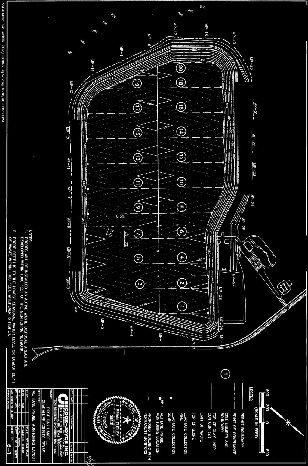
5 with the function of gas monitoring and control systems. Any underground utility trenches that cross the landfill facility boundary shall be vented and monitored regularly. 2.0 GENERAL LANDFILL GAS AND SITE CHARACTERISTICS [ (b)(1)(A)-(E) 2.1 INTRODUCTION The system of 29 LFG monitoring probes that will be installed along the perimeter of the active waste fill area have been designed based on site characteristics and will be monitored to detect the potential migration of methane gas. The potential for explosive gases to migrate underground at the facility is dependent on gas generation, site geology, hydrogeology, and liner systems beneath the waste. The predominant gas generation in the initial stages of decomposition is carbon dioxide. As time passes, methane generation increases while carbon dioxide generation decreases. Methanogenesis (methane generation) continues until accessible moisture or organic material within the solid waste disposal area is consumed. Average gas composition is anticipated to be similar to that observed at other sites of similar size and type. Typical constituents of gases generated by disposal facilities are: Gas Constituent Estimated Concentration Methane 50% Carbon Dioxide 50% Other Components <1% 2.2 SOIL CONDITIONS The site lies within the outcrop area of the upper portion of the Eocene Wilcox Group. The Wilcox Group generally consists of various amounts of sands, clays, lignite, ironstone concretions with glauconite. Onsite borings have indicated that shallow soils are interbedded, continuous and discontinuous very-fine grained sands with clays and silty clay layers with thin beds of lignite. Methane gas is lighter than air and has a tendency to move upward or horizontally depending on density of soil and other materials underground. In the event that the PART III R131028_ ATT 6.DOCX 6-2
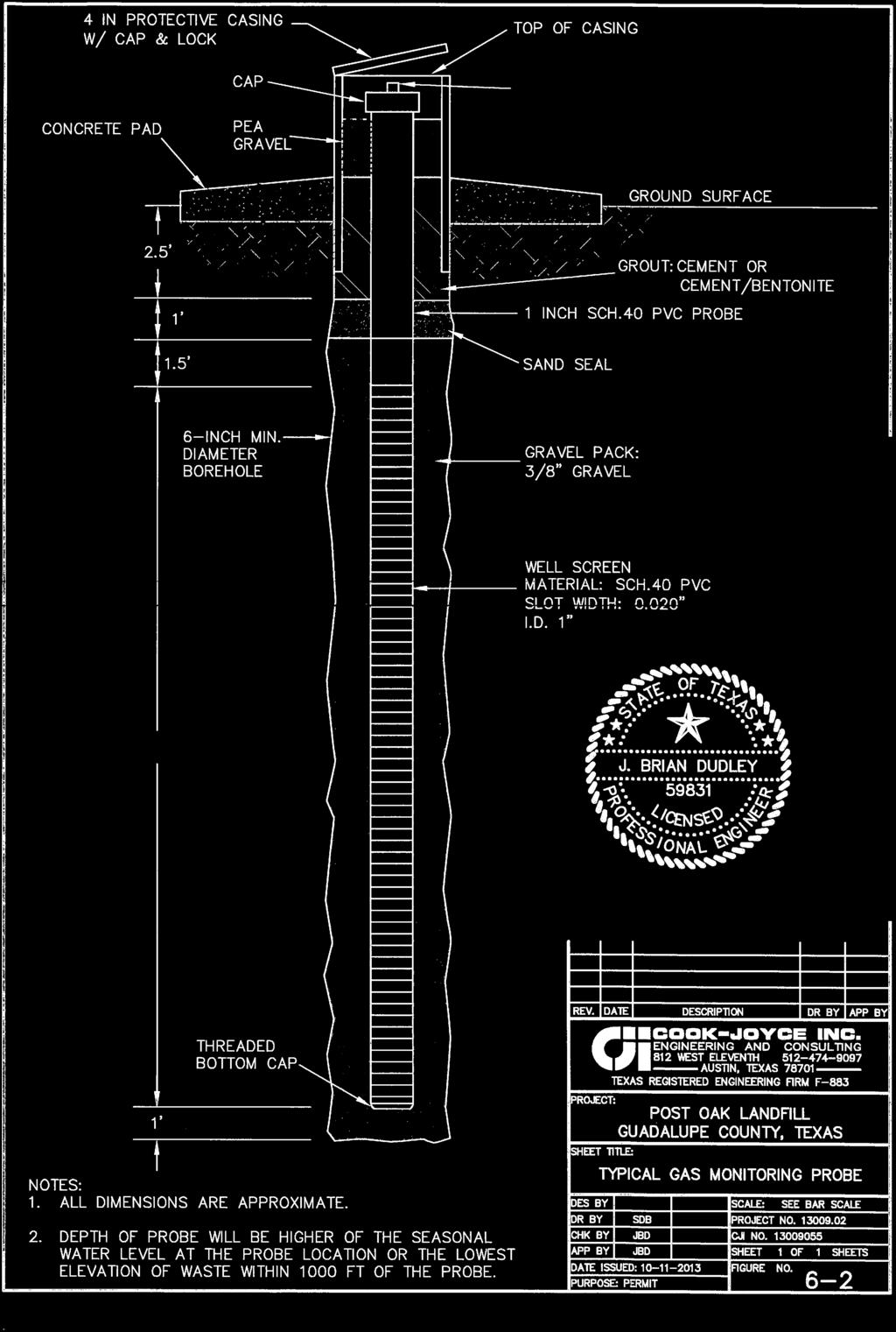
6 landfill liner system is penetrated, gas could migrate through granular soil layers adjacent to the landfill. 2.3 FACILITY STRUCTURES The facility s permit boundary contains 1003 acres, with about 331 acres designated for waste placement. There are several proposed enclosed structures within the permitted boundary as shown on Figure 6-1. These structures include an office building, gate house and vehicle maintenance building. Enclosed structures at the site with slabs or floors on-grade will have continuous methane monitoring with alarms. Semi-enclosed structures are open and well ventilated and do not require permanent methane monitoring. 2.4 UNDERGROUND UTILITIES Pipe bedding and backfill material is often a granular material and can provide a pathway for offsite methane migration along underground utilities. No active underground utility lines and/or pipelines currently cross the permit boundary. Future lines that may be placed or any previously unknown pipelines crossing the permit boundary will be managed through the use of passive vents installed near the permit boundary to prevent the off-site migration of methane at these locations. 3.0 LANDFILL GAS MONITORING PLAN 3.1 MONITORING PROBES The LFG probe system will be located outside the perimeter of the landfill along the point of compliance line and includes a total of 29 monitoring probes. Probes located within 1000 feet of the first cells will be installed during initial construction, with others phased in as the active waste disposal area is developed within 1000 feet of the monitoring network. See Figure 6-1. The probes will be installed to either the lowest seasonal water level or the lowest depth of waste within 1000 feet, whichever is higher. The LFG probes will be installed in accordance with the Figure 6-2, Monitoring Probe Detail. Boring logs and typical construction details for the LFG probes will be submitted to the TCEQ as part of the Gas Monitoring Probe Installation Report. PART III R131028_ ATT 6.DOCX 6-3
7 The executive director may require additional sampling for specified trace gases and/or more frequent monitoring. Additional monitoring may also be conducted by the facility for those locations where monitoring results indicate that landfill gas migration is occurring or is accumulating in structures 3.2 MONITORING PROBE PROCEDURES The monitoring of LFG at Post Oak Landfill will be conducted quarterly and will include at least the following data: Methane Concentration, (percent by volume) and Depth to groundwater. The gas monitoring instrument will be calibrated against known methane standards prior to each monitoring event. The equipment may also be checked against known gas concentrations in the event of methane concentrations near regulatory compliance levels, or questionable or suspicious monitoring results. The equipment will be used, maintained, and calibrated according to manufacturer s recommendations. Equipment calibration records as well as quarterly monitoring results will be maintained as part of the Facility s operating record. The gas detection devices will be equipped with a suction sampling line equipped with an air tight fitting which corresponds to an air tight fitting installed at the top of each probe. Gas from the probe will be drawn through the instrument and the direct reading of the methane concentration recorded. Other tests for gas pressure, oxygen content or other parameters may be conducted if desired. Next, the cap to the probe will be removed and the depth to groundwater is measured and recorded. Each time LFG monitoring is conducted, the sampler will inspect the integrity of the LFG monitoring probes and the condition of surface completion components such as the concrete slab, protective casing, bollards and lock. In the event that the monitoring probe system breaks down or becomes ineffective, repairs and/or replacement of damaged probes will be scheduled and implemented within 60 days. All PART III R131028_ ATT 6.DOCX 6-4
8 documentation related to the repair and/or replacement to the landfill gas system will be placed in the site operating record within seven days of completion of any repairs/replacement. 3.3 MONITORING ENCLOSED STRUCTURES Enclosed structures will have permanent, continuous methane monitoring systems, which will be checked for proper operation as suggested by the manufacturer. Semi-enclosed structures are open and well ventilated and do not require continuous methane monitoring. In the event that any continuous methane monitoring system breaks down or becomes ineffective within onsite enclosed structures, repairs and/or replacement of the system will be scheduled and implemented within 30 days. A portable gas detection device will be used to monitor structures weekly until stationary units are repaired and/or replaced. All documentation related to the repair and/or replacement to the landfill gas system will be placed in the site operating record within seven days of completion of any repairs/replacement. 4.0 ACTION PLAN This Action Plan has been developed in accordance with 30 TAC for the protection of human health and the environment. When methane levels have been detected above regulatory limit at either the LFG probes or monitoring devices within on-site structures, the landfill manager will take the following steps to ensure the protection of human health: Immediate Response - Notification will be made immediately to: TCEQ executive director, TCEQ Region Office, Local and County Officials, Emergency Response Officials and Residents within 1000 feet of the reading. Notification Within Seven Days - Within seven days of detection, the landfill manager will place a record of the methane level(s) in the operating record, PART III R131028_ ATT 6.DOCX 6-5
9 which will include the concentration levels and a description of the steps taken to protect human health. Notification With in Sixty (60) Days - A remediation plan is required to be implemented within sixty (60) days of a detection event as described in the following section. 5.0 REMEDIATION PLAN Once verification procedures have confirmed that methane levels are above regulatory limits within enclosed structures or at one of the LFG monitoring probes, a remediation plan will be implemented within 60 days of detection. The first remediation action will be to identify the cause of increased methane levels. The following are actions that may be conducted: Perform additional LFG monitoring to verify initial readings Bar-hole probing or similar testing in vicinity of the impacted area Sampling and laboratory analysis of LFG samples collected to determine concentration of methane, other trace compounds present, as well as a gas analysis to identify source. The second remediation action will be to review data obtained from the additional testing to determine an appropriate course of action to mitigate the LFG migration. Mitigation actions may include the expansion or replacement of probes, installation of passive methane venting trenches, or installation or modification of a LFG collection system in the landfill. Copies of this specific action plan will be placed in the Facility s operating record and be provided to the executive director of the TCEQ along with notification that the remediation plan has been implemented. The executive director may establish alternative schedules for demonstrating compliance with the routine methane monitoring program or gas exceedance. 6.0 LANDFILL GAS COLLECTION AND CONTROL The Post Oak MSW Landfill is a new facility designed with a waste disposal capacity greater than 2.5 million megagrams and 2.5 million cubic meters. The facility is subject to requirements PART III R131028_ ATT 6.DOCX 6-6
10 of 40 CFR Part 60, Subpart WWW - Standards of Performance for Municipal Solid Waste Landfills and must take actions to evaluate and ultimately install a gas collection and control system (GCCS). For compliance, the facility must either proceed with the design and installation of a GCCS or calculate nonmethane organic compound (NMOC) emissions on an annual basis until such time as the calculated NMOC emission rate equals or exceeds 50 megagrams per year. As Post Oak begins operations, gas emissions will be calculated annually using EPA s Landfill Gas Emissions Model v3.02 and submitted to TCEQ. Conservative default input values contained in the model will initially be used, and then within the first few years of operation, landfill gas at the site will be sampled and analyzed to develop site-specific inputs for the model. These inputs include C NMOC (concentration of NMOC) and/or k (methane generation rate constant). NMOC concentration is typically determined using a sampling probe and flame ionization detector (FID), while methane generation rate is determined using extraction wells and flow/pressure instrumentation. Specific sampling procedures and laboratory analysis methods are contained in 40 CFR and Methods 2E, 18, 25, and 25C of 40 CFR Part 60, Appendix A. Using EPA s model and default emission rates, NMOC emissions are projected to exceed 50 megagrams per year no sooner than the second year of operation and when approximately 231,000 tons of waste are landfilled (see Appendix 6A). When NMOC emissions exceed 50 megagrams per year, Post Oak will comply with 40 CFR (b)(2) rules for implementing a GCCS. Within one year, Post Oak will submit to TCEQ, a collection and control system design plan prepared by a professional engineer, with implementation meeting the schedule contained in (b)(2)(i). The gas control system will be composed of an array of collection wells installed by drilling vertically into the in-place waste. Figure 6-3 shows a typical gas collection well. The wells will be connected to a gas collection pipe system with condensate recovery traps. The gas will then be routed to a flare for destruction and/or power generation engines for electricity production. In the event that a subsurface gas migration problem is detected during operations, the GCCS can be modified to mitigate the problem by following evaluation and response procedures identified in Section 5. PART III R131028_ ATT 6.DOCX 6-7

11 FIGURES PART III R131028_ ATT 6.DOCX 6-8


12 PART III 6-9

13 PART III 6-10


14 PART III 6-11
15
16 PART III 6A-i
17 PART III 6A-i

18 PART III 6A-i