LECTURE 15 PHOTOVOLTAIC MATERIALS. ECE 371 Sustainable Energy Systems
|
|
|
- Rosemary Doyle
- 5 years ago
- Views:
Transcription
1 LECTURE 15 PHOTOVOLTAIC MATERIALS ECE 371 Sustainable Energy Systems 1

2 SHADING IMPACTS ON I-V CURVE The output of the PV cell is reduced significantly when even a small portion of it is shaded Even a single shaded cell in a module can easily cut output by half External diodes added by manufacturers can help preserve the performance of PV cells These diodes are added in parallel with modules or blocks of cells within a module 2
3 SHADING PHYSICS The following figure shows when one cell in a module of n-cells is shaded 3
4 SHADING PHYSICS P P S S P SH S P SH n S P n SH R I n V V R R R R I n V V V V R R I V n n V V n n V R R I V V + << + + = = + = = + = ) ( ) ( ) 1 ( ) 1 ( ) ( 1 1 4
5 SHADING PHYSICS The I-V curve is modified accordingly 5
6 SHADING PHYSICS The following figure shows a cell experiencing 50% shading 6
7 SHADING PHYSICS The shown procedure can be extended to develop I-V curves under various shading conditions 7
8 BYPASS DIODE FOR SHADING MITIGATION Shading can Shift the I-V curve Create damaging hot spot in shaded cell Each cell at its MPP adds 0.5 V to the output of a module when it is in the sun If a cell is shaded, it drops the voltage by a significant amount 8
9 BYPASS DIODE FOR SHADING MITIGATION The following figure shows a cell in a string When there is no shading When there is shading The voltage drop problem is mitigated by a bypass diode 9
10 BYPASS DIODE FOR SHADING MITIGATION 10
11 BYPASS DIODE FOR SHADING MITIGATION In PV modules it will not be practical to add a diode across each cell Manufacturers often provide a bypass diode across each module This does not mitigate the impact of a cell being shaded, but it mitigates the significant voltage drop in an array made of many modules 11
12 BYPASS DIODE FOR SHADING MITIGATION The following shows a bypass diode for 1/3 of the cells 12
13 BYPASS DIODE FOR SHADING MITIGATION 13
14 BYPASS DIODE FOR SHADING MITIGATION Just as cells are connected in series to increase module voltage, modules can be wired in series to increase array voltage Since a single cell can drag down the current in a module, a few shaded cells in a single module can drag down the power delivered by the string in an array 14
15 BYPASS DIODE FOR SHADING MITIGATION 15
16 BLOCKING DIODES When strings of modules are wired in parallel, a similar problem can arise when shading is impacting one or two strings The voltage of the string with shaded modules will drop, and other parallel strings will start to feed the shaded string This can be mitigated by blocking diodes at top of each string, which are called isolation diodes 16

17 BLOCKING DIODES 17
18 MAXIMUM POWER POINT TRACKERS PV arrays should operate at the optimum (MPP) in the I-V curves that are shifting all the time This means incorporating a maximum power point tracker (MPPT) as a part of the system The cost and complexity may not justify MPPT and they are omitted in some applications 18
19 PV Systems We will discuss analysis and design of PV systems for three configurations Grid-connected Systems Small-scale behind-the-meter systems (rooftops) Large-scale on the utility side of the meter Stand-alone Systems Off-grid systems using batteries for energy storage (picoscale to solar-powered homes) 19
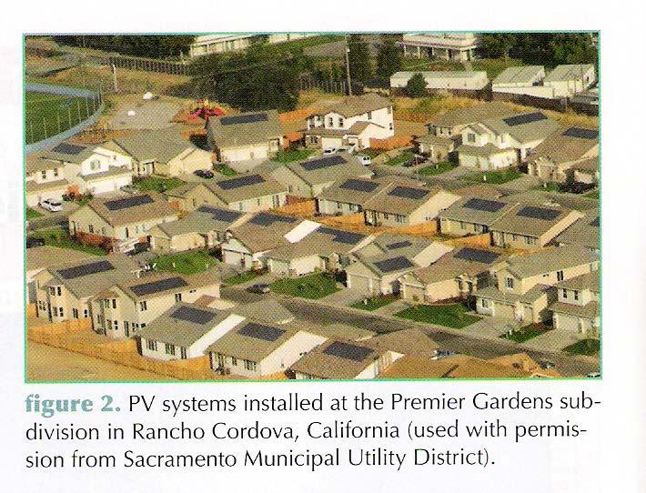
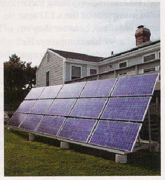
20 INTRODUCTION Behind-the-meter grid-connected systems have a number of desirable attributes Located on owners property Compete against the retail electricity prices Less expensive (no need for batteries or backup generators) 20
21 GRID-CONNECTED SYSTEMS The following figure shows the PV system feeding the utility grid 21
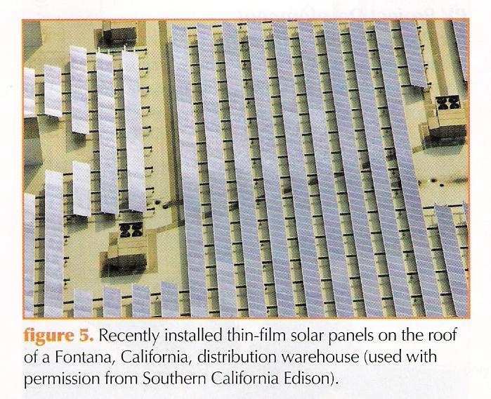
22 GRID-CONNECTED SYSTEMS For residential systems it is rated for 1-10 kw of generation capacity A similar system on a commercial building is rated for 10 kw to 2 MW Rooftops and parking lots Although the above two systems are physically similar, rate structures and financial incentives are different 22
23 GRID-CONNECTED SYSTEMS 23

24 GRID-CONNECTED SYSTEMS 24
25 GRID-CONNECTED SYSTEMS The following figure shows various components in a typical home-size system 25

26 GRID-CONNECTED SYSTEMS 26
27 GRID-CONNECTED SYSTEMS 27

28 GRID-CONNECTED SYSTEMS 28

29 GRID-CONNECTED SYSTEMS Sweden-based architect Mans Tham went halfway around the world with this design for a serpent-shaped solar skin for the Sana Monica freeway. This proposal adds 237 acres of solar power to the middle of Los Angeles. 29

30 GRID-CONNECTED SYSTEMS 30

31 GRID-CONNECTED SYSTEMS 31
32 GRID-CONNECTED SYSTEMS Micro-inverters are an alternative approach to a single inverter system 32
33 GRID-CONNECTED SYSTEMS Significant advantages are Each module has its own MPPT Bypass diodes not needed Poor performing modules does not bring down an entire string A single inverter malfunction does not take down the entire array Facilitate remote monitoring that can identify performance issues module by module 33
34 GRID-CONNECTED SYSTEMS Modules can be replaced individually without affecting the rest of the array Modules can be wired by conventional household AC components that are commercially available AC breakers are safer and cheaper than DC counterparts AC modules makes fitting an array to an irregular roof surface easier 34
35 GRID-CONNECTED SYSTEMS Large grid-connected systems may use a series of individual inverters or a central inverter system 35
36 GRID-CONNECTED SYSTEMS Net metering can save a homeowner a substantial amount Time-of-use can introduce complications 36

37 GRID-CONNECTED SYSTEMS The following table shows advantages of installing rooftop PV systems 37
38 GRID-CONNECTED SYSTEMS It is also possible to use a 2 meter system One to measure PV generated power Another to measure power used in the building This allows separate rates Feed-in Tariff (FIT) rate Encourage PV adoption with generous rates (maybe/may be not) Residential/Commercial consumption rate 38

39 GRID-CONNECTED SYSTEMS 39
40 STAND-ALONE SYSTEMS The next figure shows an off-grid, stand-alone system with battery storage and a generator for backup power 40

41 STAND-ALONE SYSTEMS 41

42 STAND-ALONE SYSTEMS 42
43 STAND-ALONE SYSTEMS 43

44 STAND-ALONE SYSTEMS 44
45 STAND-ALONE SYSTEMS The following is the Ohm s law that is applied to resistors V = R I I = V/R When plotted on I-V graph, it is a straight line with a slope of 1/R As R increases (load decreases), the operating point moves to the right along the PV s I-V characteristic 45

46 STAND-ALONE SYSTEMS 46
47 STAND-ALONE SYSTEMS Since PVs provide power during daylight hours, a energy storage device is needed The energy storage device is usually a battery The I-V relationship for a battery is V = V B + R i I Where V B = ideal battery voltage in volts R i = internal battery resistance in ohms ( Ω) 47

48 STAND-ALONE SYSTEMS The following figure shows the characteristics of an ideal battery 48
49 STAND-ALONE SYSTEMS The following figure shows the characteristics of a real battery 49
50 STAND-ALONE SYSTEMS This simple equivalent circuit representation is complicated by the following factors Open-circuit voltage V B depends on State of charge Battery temperature How long it has been resting without any current flowing Internal resistance R i is a function of Battery temperature State of charge Age of battery Different for charge and discharge 50
51 STAND-ALONE SYSTEMS 51