FOULING MANAGEMENT IN CRUDE OIL PREHEAT TRAINS/DHP UNITS
|
|
|
- Damian Allison
- 5 years ago
- Views:
Transcription


1 FOULING MANAGEMENT IN CRUDE OIL PREHEAT TRAINS/DHP UNITS Presenter: Metin BECER Process Superintendent Turkish Petroleum Refineries Corporation 15/11/16 Lisbon-Portugal ERTC


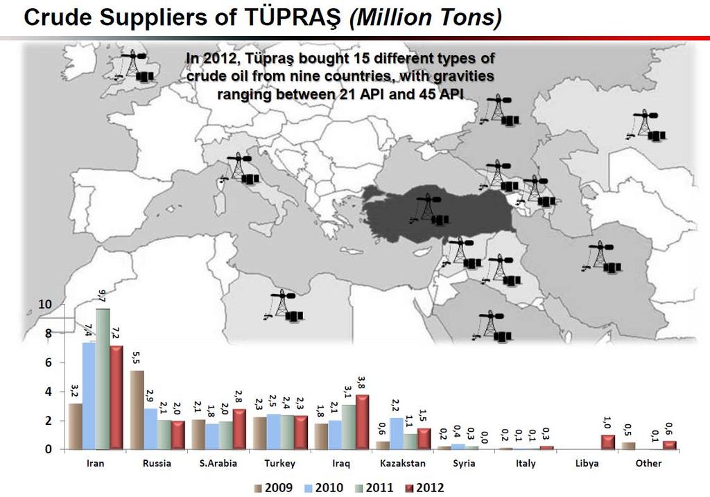
2 Turkey s Leading Industrial Enterprise Kırıkkale Rafinerisi CCR Ünitesinin Modellenmesi & Petroleum Refinery Oktan Total Optimizasyonu of 28,1 M ton refining capacity with 4 refineries Privatized in 2006 and owned by Koc Holding (%51) 2 2

3 Kırıkkale Rafinerisi CCR Ünitesinin Modellenmesi & Oktan Optimizasyonu 3 3

4 44

5 OUTLINE of the Presentation The Fouling problem in the Refinery Units 1. The Crude Oil Units, 2. The DHP Units TUPRAS solution for the FOULING MONITORING Details about the HEXMON programme 5 5
6 FOULING MANAGEMENT IN CRUDE OIL PREHEAT TRAINS


7 FOULING PROBLEM Fouling in heat exchangers is one of the major problems in chemical process industries. In refineries, considered as the main source for energy loss, reaching up to 2% of the refinery s total energy consumption. Profound interest in minimizing the energy consumptions due to the challenging refinery margins Decrease in thermal and hydraulic performance of the heat exchangers Higher heat load is required in the furnace which leads more fuel gas/ fuel oil consumption in the furnace Increase in greenhouse gas emissions 7 7


8 FOULING PROBLEM (cont d) Fouling in the crude oil preheat trains is considered as ~20% of all heat exchanger fouling. In the current process, the crude oil is being heated via products (and pump-around streams in first and second pre-heat exchanger trains prior to furnace. In order to reduce the energy consumption in the furnace, the efficiency of the heat exchangers in the preheat trains is very crucial. E 7108 E 7109 E 7110 E 7111 E 7113 E 7115 E 7116 E 7117 E 7118 E 7119 E


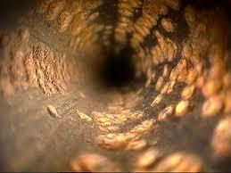
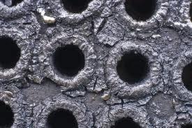
9 FOULING (cont d) Fouling is mainly defined as the formation of deposits on heat exchange surfaces due to sedimentation, crystallization, organic and biological growths, chemical reactions, corrosion products, or their combination.. The deposit formation due to chemical reactions may be complex in nature, and will include several mechanisms such as autoxidation, polymerization, cracking or coke formation. If there is ambient oxygen, it will catalyze the gum formation which is usually seen in hydro-processing units. Gum-like material will also be observed in jet fuel, gas oil and similar products upon heating due to the precipitation of paraffinic hydrocarbon mixtures. Thus, temperature, pressure and flow rate are important operating parameters which affect the fouling formation. Usually, the temperature increase will lead to an exponential increase in the chemical reaction rates; pressure increases the solubility of the oxygen thus will increase the gum formation rate. Flow rates, however, will have a reverse effect such that higher velocities make it difficult for deposits to attach to the surface. 9 9

10 R&D in TUPRAŞ Refineries R&D study has been started in the refinery in order to find a better way to monitor the fouling in HEAT EXCHANGERS (CRUDE OIL and DHP units) The study has been continued both for CRUDE OIL and DIESEL HYDROPROCESSING UNITS and as well as the all prone to fouling heat exchangers throughout the refinery, The study has been partially sponsored by the government The main findings related with the CRUDE OIL/DHP plants will be shared in this presentation The main aim is to monitor the fouling, (to find out the reasons behind the fouling, to make a fouling model for the units) and to estimate and to optimize the cleaning periods of the exchangers 10


11 STUDIES ON CRUDE OIL UNIT SITE 11


12 ANALYSIS ON SITE All the exchangers are bypassed Mechanically cleaned Steam outed, and the thermocouples are installed 12

13 ANALYSIS ON SITE 13


14 ANALYSIS ON LABORATORY In order to calculate the physical properties of the crude oil and product streams and therefore to better evaluate the parameters effecting to the fouling mechanisms a R&D laboratory has been established. HPLC Total Aromatics ANTEK 9000 S Sulphur Content Oxygen Content Anton Paar Black Product Density ASTM D86- Atm. Distillation Crude Oil Acid/Base Number Anton Paar White Product Density 14


15 SOFTWARE DEVELOPMENT A Software has been developed by Tupras engineers Sample screenshot is shown below 15
16 SOFTWARE DEVELOPMENT In the software, Simple components, hydrocarbon mixtures and petroleum fractions have been identified All the physical properties (density, boiling point, condensation point, viscosity, dew point, vapor pressure, thermal conductivity) of the components with respect to different operational conditions can be calculated in the software All the relevant exchangers has been identified in terms of Data Sheet specifications, The algorithm has been adapted in order to calculate the fouling factor of the heat exchangers in the real time operational conditions (temperature, pressure, flow, distillation data) and by taking the heat exchangers design specifications into consideration. 16
 and Bell-Delaware (shell side) approaches THEN, the fouling factor (Rf) for the")

17 FOULING MANAGEMENT ALGORITHM ALGORITHM calculates the Uc (clean heat transfer coefficient) for the heat exchangers at the operational conditions by using Kern (tube side) and Bell-Delaware (shell side) approaches THEN, the fouling factor (Rf) for the heat exchangers are calculated by using the Ud (calculated from the operational data) A METHOD for MONITORING Rf is developed.. Needs an exact knowledge of the overall thermal resistance of the exchangers in the same flow and operational conditions, but not fouled 17
18 SIMULATION RESULTS, a Comparison The output of the programme has been compared with the commercial software when the exchangers are clean, Rf = 0 (just after maintanence), Both for 1 st and 2 nd preheat trains, the simulated tube-shell outlet temperatures are in well coincidence with the real data and as well as the commercial outputs. 18
19 SIMULATION RESULTS (cont d) Operational tube outlet temperatures of the clean heat exchangers were found to be consistent with the calculated outlet temperature Software is capable of simulating the clean case. Also observed that the results of the software were closer to the operational data in comparison to the commercial software in SOR conditions 19
20 CRUDE OIL UNIT 1 ST PREHEAT TRAIN 20
21 Sıcaklık ( C) Sıcaklık ( C) SIMULATION RESULTS, CRUDE OIL 1 st PREHEAT TRAIN SIMULATION RESULTS E E , , , ,004 0, , , , , , , ,006-0, , Tube Outlet Temp Tube Outlet Temperature Simulation Result Rf Shell Outlet Temp Shell Outlet Temperature Simulation Result Rf Simulation result of crude oil-mid pumparound heat exchanger after the cleaning time to 1 year period 21
22 SIMULATION RESULTS, CRUDE OIL 1 st PREHEAT TRAIN SIMULATION RESULTS for Rf values 0,006 Rf ,005 0,004 0,003 0,002 0, ,001 Simulation result of crude oil-mid pumparound heat exchanger after the cleaning time for 1 year period. 22
23 Rf values ( ) 23 23
24 Tuz ( mg/l) SIMULATION RESULTS, CRUDE OIL 1 st PREHEAT TRAIN SIMULATION RESULTS IMPACT of INORGANICS, METAL, API ETC.. Subject of Phase II study of this project 45 SALT API

25 2 nd PREHEAT TRAIN Atm resid is 360 C, crude oil is around 200 C 25
26 Sıcaklık Sıcaklık ( ( C) ( C) C) Sıcaklık Sıcaklık ( C) C) SIMULATION RESULTS 2 nd PREHEAT TRAIN SIMULATION RESULTS Rf E E7118 E , , ,004 0,0035 0,005 0, ,002 0, ,0005 0,0035 0, ,005 0,004 0, ,005 0,003 0, , ,0025 0,001 0,003 0, , , ,0015 0,002 0,01 0,0005 0, ,002 0, , , , , ,0015-0,0005 0, ,0025-0, ,001 0,001-0,01-0, , ,025 0,0005-0, ,0035-0,001-0, ,03-0, , Tube Tube Outlet Outlet Temp Temp Tube Tube Outlet Outlet Temperature Temperature Simulation Simulation Result Result Rf Tube Outlet Temp Tube Outlet Temperature Simulation Result Rf Rf Tube Outlet Temp Tube Outlet Temperature Simulation Result Rf Simulation result of crude oil-mid oil-bottom oil-heavy oil-top oil-light oil-atm. PA. resid. diesel PA. Heat Heat Heat exchanger exchanger after after after the the the cleaning time to the mid 2012 (totally 1 year) 26
27 SIMULATION Rf results (2nd train) 27
28 Kükürt ( % M/M) Asfalten ( % M/M) SIMULATION RESULTS, CRUDE OIL 2 nd PREHEAT TRAIN SIMULATION RESULTS IMPACT of ASPHALTENES, SULPHUR, API, SURFACE TEMPERATURE, ATM. RESID ETC.. Subject of Phase II study of this project 3,500 3,0002,5 2, ,5 2, ,500 0,5 1,000 0,500 SULPHUR ASPHALTENE API ,
29 FOULING MANAGEMENT IN DHP Unit PREHEAT TRAINS
30 ANOTHER STUDY TUPRAS has also completed another study in DIESEL HYDROPROCESSING UNIT HEAT EXCHANGERS FOULING Dealing with the FOULING mostly due to oxygen in the imported diesel feed and also refinery cracked diesel streams 30

31 DHP Unit preheat exchangers 31
32 DHP Unit preheat exchangers Subject to FOULING (due to autoxidation and free radical polymerization reactions) especially when having feed from storage or cracked feed stocks Have a huge impact on furnace duty/unit cycle time Careful MONITORING is a MUST 32
33 DHP PREHEAT EXCH. Rf values ( ) Chemical treatment programme/o2 stripper column/h2 sweeping FINALLY UNDER CONTROL 33
34 DHP PREHEAT EXCH. FOULING ( ) 34
35 DHP Unit preheat exchangers Hexmon monitoring is an important tool for both the unit engineers and the control operators and is widely used in TUPRAS refineries The changes in feed rate/feed quality/reactor temperatures/import-storage tank ratio/cracked feed ratio are all have impacts on the FOULING mechanisms The fouling trends are daily monitored and any change is noted. Thus the furnace duty is aimed to be under control together with the catalyst deactivation rates. 35
36 RESULTS and DISCUSSION TUPRAS owns a simulation program that has the capability of simulating the clean overall heat transfer coefficient at the current operating conditions and by gathering data from the real time values, calculates the FOULING FACTOR FUTURE STUDY: As the fouling starts to occur in the exchangers, the parameters effecting to the fouling will be determined by laboratory analysis program, then the fouling models will be derived, and OPTIMIZATION of cleaning (by-passing) will be decided with a optimizer tool adapted to the program In the network simulation, the impact of any exchanger s fouling and extra duty to the furnace will be determined A better CLEANING time schedule by REAL TIME MONITORING will mean LESS LOSS due to FOULING 36

37 SUMMARY FOULING monitoring is a highly critical parameter for the refineries. THEN, one may decide on the excellent time about the unit or heat exchanger shut down/bypass by taking in to account of furnace duty. With the help of the HEXMON programme, TUPRAS engineers are easily adapting their critical and prone to fouling heat exchangers to the system and routinely monitoring the fouling trends. Widely used in all of the 4 refineries in nearly all units. 37

38 Kırıkkale Rafinerisi CCR Ünitesinin Modellenmesi & Oktan Optimizasyonu Thank you for your time and consideration. 38